

ASUS E9142 User Manual

Motherboard
P8B75-M

ii
E9142
Revised Edition (v4)
March 2014
Copyright © 2014 ASUSTeK Computer Inc. All Rights Reserved.
No part of this manual, including the products and software described in it, may be reproduced,
transmitted, transcribed, stored in a retrieval system, or translated into any language in any form or by any
means, except documentation kept by the purchaser for backup purposes, without the express written
permission of ASUSTeK Computer Inc. (“ASUS”).
Product warranty or service will not be extended if: (1) the product is repaired, modied or altered, unless
such repair, modication of alteration is authorized in writing by ASUS; or (2) the serial number of the
product is defaced or missing.
ASUS PROVIDES THIS MANUAL “AS IS” WITHOUT WARRANTY OF ANY KIND, EITHER EXPRESS
OR IMPLIED, INCLUDING BUT NOT LIMITED TO THE IMPLIED WARRANTIES OR CONDITIONS OF
MERCHANTABILITY OR FITNESS FOR A PARTICULAR PURPOSE. IN NO EVENT SHALL ASUS, ITS
DIRECTORS, OFFICERS, EMPLOYEES OR AGENTS BE LIABLE FOR ANY INDIRECT, SPECIAL,
INCIDENTAL, OR CONSEQUENTIAL DAMAGES (INCLUDING DAMAGES FOR LOSS OF PROFITS,
LOSS OF BUSINESS, LOSS OF USE OR DATA, INTERRUPTION OF BUSINESS AND THE LIKE),
EVEN IF ASUS HAS BEEN ADVISED OF THE POSSIBILITY OF SUCH DAMAGES ARISING FROM ANY
DEFECT OR ERROR IN THIS MANUAL OR PRODUCT.
SPECIFICATIONS AND INFORMATION CONTAINED IN THIS MANUAL ARE FURNISHED FOR
INFORMATIONAL USE ONLY, AND ARE SUBJECT TO CHANGE AT ANY TIME WITHOUT NOTICE,
AND SHOULD NOT BE CONSTRUED AS A COMMITMENT BY ASUS. ASUS ASSUMES NO
RESPONSIBILITY OR LIABILITY FOR ANY ERRORS OR INACCURACIES THAT MAY APPEAR IN THIS
MANUAL, INCLUDING THE PRODUCTS AND SOFTWARE DESCRIBED IN IT.
Products and corporate names appearing in this manual may or may not be registered trademarks or
copyrights of their respective companies, and are used only for identication or explanation and to the
owners’ benet, without intent to infringe.
Offer to Provide Source Code of Certain Software
This product may contain copyrighted software that is licensed under the General Public License (“GPL”)
and under the Lesser General Public License Version (“LGPL”). The GPL and LGPL licensed code in this
product is distributed without any warranty. Copies of these licenses are included in this product.
You may obtain the complete corresponding source code (as dened in the GPL) for the GPL Software,
and/or the complete corresponding source code of the LGPL Software (with the complete machinereadable “work that uses the Library”) for a period of three years after our last shipment of the product
including the GPL Software and/or LGPL Software, which will be no earlier than December 1, 2011, either
(1) for free by downloading it from http://support.asus.com/download;
or
(2) for the cost of reproduction and shipment, which is dependent on the preferred carrier and the location
where you want to have it shipped to, by sending a request to:
ASUSTeK Computer Inc.
Legal Compliance Dept.
15 Li Te Rd.,
Beitou, Taipei 112
Taiwan
In your request please provide the name, model number and version, as stated in the About Box of the
product for which you wish to obtain the corresponding source code and your contact details so that we
can coordinate the terms and cost of shipment with you.
The source code will be distributed WITHOUT ANY WARRANTY and licensed under the same license as
the corresponding binary/object code.
This offer is valid to anyone in receipt of this information.
ASUSTeK is eager to duly provide complete source code as required under various Free Open Source
Software licenses. If however you encounter any problems in obtaining the full corresponding source code
we would be much obliged if you give us a notication to the email address gpl@asus.com, stating the
product and describing the problem (please do NOT send large attachments such as source code archives
etc to this email address).

iii
Contents
Safety information ...................................................................................... vi
About this guide ......................................................................................... vi
P8B75-M specications summary ........................................................... viii
Chapter 1 Product introduction
1.1 Welcome! ...................................................................................... 1-1
1.2 Package contents .........................................................................
1-1
1.3 Special features ............................................................................
1-1
1.3.1 Product highlights ...........................................................
1-1
1.3.2 Innovative ASUS features ...............................................
1-3
1.4 Before you proceed .....................................................................
1-5
1.5 Motherboard overview .................................................................
1-6
1.5.1 Placement direction ........................................................
1-6
1.5.2 Screw holes ....................................................................
1-6
1.5.3 Motherboard layout .........................................................
1-7
1.5.4 Layout contents ...............................................................
1-7
1.6 Central Processing Unit (CPU) ...................................................
1-8
1.6.1 Installing the CPU ...........................................................
1-9
1.6.2 CPU heatsink and fan assembly installation ..................
1-11
1.7 System memory .........................................................................
1-13
1.7.1 Overview .......................................................................
1-13
1.7.2 Memory congurations ..................................................
1-13
1.7.3 Installing a DIMM ..........................................................
1-19
1.7.4 Removing a DIMM ........................................................
1-19
1.8 Expansion slots ..........................................................................
1-20
1.8.1 Installing an expansion card .........................................
1-20
1.8.2 Conguring an expansion card .....................................
1-20
1.8.3 PCI slot .........................................................................
1-20
1.8.4 PCI Express x4 slot .......................................................
1-20
1.8.5 PCI Express x16 slot .....................................................
1-20
1.9 Jumpers ......................................................................................
1-21
1.10 Connectors .................................................................................
1-23
1.10.1 Rear panel connectors ..................................................
1-23
1.10.2 Internal connectors .......................................................
1-25
1.11 Onboard switches ......................................................................
1-32
1.12 Onboard LEDs ............................................................................
1-33

iv
Contents
1.13 Software support ........................................................................ 1-34
1.13.1 Installing an operating system ......................................
1-34
1.13.2 Support DVD information ..............................................
1-34
1.13.3 Intel
®
SBA support ......................................................... 1-35
Chapter 2 BIOS information
2.1 Managing and updating your BIOS ............................................ 2-1
2.1.1 ASUS Update utility ........................................................
2-1
2.1.2 ASUS EZ Flash 2 ............................................................
2-2
2.1.3 ASUS CrashFree BIOS 3 utility ......................................
2-3
2.1.4 ASUS BIOS Updater .......................................................
2-4
2.2 BIOS setup program ....................................................................
2-6
2.3 Main menu ..................................................................................
2-10
2.3.1 System Language [English] ..........................................
2-10
2.3.2 System Date [Day xx/xx/xxxx] .......................................
2-10
2.3.3 System Time [xx:xx:xx] .................................................
2-10
2.3.4 Security .........................................................................
2-10
2.4 Ai Tweaker menu ........................................................................
2-12
2.4.1 CPU bus speed : DRAM speed ratio mode [Auto] ........
2-12
2.4.2 Memory Frequency [Auto] .............................................
2-12
2.4.3 EPU Power Saving Mode [Disabled] ............................
2-13
2.4.4 GPU Boost [OK] ............................................................
2-13
2.4.5 DRAM Timing Control ...................................................
2-13
2.4.6 CPU Power Management .............................................
2-13
2.4.7 Offset Mode Sign [+] .....................................................
2-14
2.4.8 DRAM Voltage [Auto] ....................................................
2-14
2.4.9 VCCIO Voltage [Auto] ...................................................
2-14
2.4.10 VCCSA Voltage [Auto] ..................................................
2-14
2.4.11 CPU PLL Voltage [Auto] ................................................
2-14
2.4.12 PCH Voltage [Auto] .......................................................
2-15
2.4.13 Load-Line Calibration [Auto] .........................................
2-15
2.5 Advanced menu .........................................................................
2-15
2.5.1 Trusted Computing ........................................................
2-16
2.5.2 CPU Conguration ........................................................
2-16
2.5.3 PCH Conguration ........................................................
2-17
2.5.4 SATA Conguration .......................................................
2-17

v
Contents
2.5.5 System Agent Conguration ......................................... 2-18
2.5.6 ME Subsystem ..............................................................
2-18
2.5.7 AMT Conguration ........................................................
2-19
2.5.8 USB Conguration ........................................................
2-19
2.5.9 Onboard Devices Conguration ....................................
2-20
2.5.10 APM ..............................................................................
2-21
2.6 Monitor menu .............................................................................
2-22
2.5.11 Network Stack ...............................................................
2-22
2.6.1 CPU Temperature / MB Temperature
[xxxºC/xxxºF] ...... 2-23
2.6.2 CPU / Chassis Fan Speed [xxxx RPM] or [Ignore] / [N/A] 2-2
3
2.6.3 CPU Q-Fan Control [Enabled] ......................................
2-23
2.6.4 Chassis Q-Fan Control [Enabled] .................................
2-24
2.6.5 CPU Voltage, 3.3V Voltage, 5V Voltage, 12V Voltage ..
2-24
2.6.6 Anti Surge Support [Enabled] .......................................
2-24
2.7 Boot menu ..................................................................................
2-25
2.7.1 Bootup NumLock State [On] .........................................
2-25
2.7.2 Full Screen Logo [Enabled] ...........................................
2-25
2.7.3 Wait for ‘F1’ If Error [Enabled] .......................................
2-25
2.7.4 Option ROM Messages [Force BIOS] ...........................
2-26
2.7.5 Setup Mode [EZ Mode] .................................................
2-26
2.7.6 UEFI/Legacy Boot [Enabled both UEFI and Legacy] ....
2-26
2.7.7 PCI ROM Priority [Legacy ROM] ..................................
2-26
2.7.8 Boot Option Priorities ....................................................
2-26
2.7.9 Boot Override ................................................................
2-26
2.8 Tools menu .................................................................................
2-27
2.8.1 ASUS EZ Flash 2 Utility ................................................
2-27
2.8.2 ASUS O.C. Prole .........................................................
2-27
2.8.3 ASUS SPD Information .................................................
2-27
2.9 Exit menu ....................................................................................
2-28
Appendices
Notices .......................................................................................................A-1

vi
Safety information
Electrical safety
• To prevent electric shock hazard, disconnect the power cable from the electric outlet
before relocating the system.
• When adding or removing devices to or from the system, ensure that the power cables
for the devices are unplugged before the signal cables are connected. If possible,
disconnect all power cables from the existing system before you add a device.
• Before connecting or removing signal cables from the motherboard, ensure that all
power cables are unplugged.
• Seek professional assistance before using an adapter or extension cord. These devices
could interrupt the grounding circuit.
• Ensure that your power supply is set to the correct voltage in your area. If you are not
sure about the voltage of the electrical outlet you are using, contact your local power
company.
• If the power supply is broken, do not try to x it by yourself. Contact a qualied service
technician or your retailer.
Operation safety
•
Before installing the motherboard and adding devices on it, carefully read all the manuals
that came with the package.
•
Before using the product, ensure that all cables are correctly connected and the power
cables are not damaged. If you detect any damage, contact your dealer immediately.
•
To avoid short circuits, keep paper clips, screws, and staples away from connectors,
slots, sockets and circuitry.
•
Avoid dust, humidity, and temperature extremes. Do not place the product in any area
where it may become wet.
•
Place the product on a stable surface.
•
If you encounter technical problems with the product, contact a qualied service
technician or your retailer.
About this guide
This user guide contains the information you need when installing and conguring the
motherboard.
How this guide is organized
This guide contains the following parts:
•
Chapter 1: Product introduction
This chapter describes the features of the motherboard and the new technology it
supports.
• Chapter 2: BIOS information
This chapter tells how to change system settings through the BIOS Setup menus.
Detailed descriptions of the BIOS parameters are also provided.

vii
Conventions used in this guide
To ensure that you perform certain tasks properly, take note of the following symbols used
throughout this manual.
DANGER/WARNING: Information to prevent injury to yourself when trying to
complete a task.
CAUTION: Information to prevent damage to the components when trying to
complete a task.
NOTE: Tips and additional information to help you complete a task.
IMPORTANT: Instructions that you MUST follow to complete a task.
Where to nd more information
Refer to the following sources for additional information and for product and software
updates.
1. ASUS websites
The ASUS website provides updated information on ASUS hardware and software
products. Refer to the ASUS contact information.
2. Optional documentation
Your product package may include optional documentation, such as warranty yers,
that may have been added by your dealer. These documents are not part of the
standard package.
Typography
Bold text Indicates a menu or an item to select.
Italics
Used to emphasize a word or a phrase.
<Key> Keys enclosed in the less-than and greater-than sign means
that you must press the enclosed key.
Example: <Enter> means that you must press the Enter or
Return key.
<Key1>+<Key2>+<Key3> If you must press two or more keys simultaneously, the key
names are linked with a plus sign (+).
Example: <Ctrl>+<Alt>+<D>

viii
P8B75-M specications summary
(continued on the next page)
CPU LGA1155 socket for Intel® 3rd/2nd Generation Core™ i7 /
Core™ i5 / Core™ i3, Pentium®, Celeron® processors
Supports Intel 22/32nm CPU
Supports Intel® Turbo Boost Technology 2.0
* The Intel® Turbo Boost Technology 2.0 support depends on the
CPU types.
** Refer to www.asus.com for Intel® CPU support list.
Chipset Intel® B75 Express Chipset
Memory 4 x DIMM, max. 32GB, DDR3 /2200(O.C.) /2000(O.C.) /1800(O.C.)
/1600 / 1333 / 1066 MHz, non-ECC,
un-buffered memory
Dual-channel memory architecture
* DDR3 1600 MHz and above memory frequency is supported by
Intel® 3rd generation processors.
** Refer to www.asus.com for the latest Memory QVL (Qualied
Vendors List).
*** When you install a total memory of 4GB capacity or more,
Windows® 32-bit operating system may only recognize less
than 3GB. We recommend a maximum of 3GB system memory
if you are using a Windows® 32-bit operating system.
Graphics Integrated graphics processor
Multi-VGA output support: HDMI, DVI-D, and D-Sub ports
Supports HDMI with max.resolution of 1920 x 1200 @60Hz
Supports DVI with max.resolution of 1920 x 1200 @60Hz
Supports D-Sub with max. resolution of 2048 x 1536 @75Hz
Maximum shared memory of 1 GB
Expansion slots 1 x PCI Express 3.0/2.0 x16 slot*
1 x PCI Express 2.0 x4 slot
2 x PCI slots
* PCIe 3.0 speed is supported by Intel® 3rd generation Core™
processors.
Storage Intel® B75 Express Chipset:
- 5 x Serial ATA 3.0 Gb/s connectors (blue)
- 1 x Serial ATA 6.0 Gb/s connector (gray)
LAN
Realtek® 8111F-VB-CG PCIe Gigabit LAN controller
Audio VIA® VT1708S 8-channel* High Denition Audio CODEC
- Supports jack-detection, multi-streaming, anti-pop function,
and front panel jack-retasking
* Use a chassis with HD audio module in the front panel to
support an 8-channel audio output.
USB Intel® B75 Express Chipset
- 4 x USB 3.0/2.0 ports (2 ports at mid-board, 2 ports at back
panel)
- 8 x USB 2.0/1.1 ports (4 ports at mid-board, 4 ports at back
panel)

ix
P8B75-M specications summary
ASUS unique features ASUS Exclusive Features:
- ASUS EPU
- GPU Boost
- Network iControl featuring instant network bandwidth
domination for top network program in use
- ASUS USB 3.0 Boost
- MemOK!
- ASUS AI Suite II
- Ai Charger
- ASUS Anti-Surge Protection
- ASUS UEFI BIOS featuring graphics user interface
ASUS Quiet Thermal Solution:
- ASUS Q-Fan 2
- ASUS Fan Xpert
ASUS EZ DIY:
- ASUS CrashFree BIOS 3
- ASUS EZ Flash 2
- ASUS MyLogo 2™
Rear panel ports 1 x PS/2 keyboard port (purple)
1 x PS/2 mouse port (green)
1 x HDMI port
1 x DVI-D port
1 x D-Sub port
1 x LAN (RJ-45) port
4 x USB 2.0/1.1 ports
2 x USB 3.0/2.0 ports (blue)
3 x Audio jacks
Internal connectors/
switches/ buttons
1 x USB 3.0/2.0 connector supports additional 2 USB 3.0/2.0
ports
2 x USB 2.0/1.1 connectors support additional 4 USB 2.0/1.1
ports
5 x SATA 3.0 Gb/s connectors (blue)
1 x SATA 6.0 Gb/s connector (gray)
1 x CPU fan connector
2 x Chassis fan connectors
1 x Chassis intrusion connector
1 x TPM connector
1 x COM connector
1 x LPT connector
1 x Front panel audio connector (AAFP)
1 x S/PDIF output connector
1 x System panel connector
1 x Speaker connector
1 x 24-pin ATX power connector
1 x 4-pin ATX 12V power connector
1 x MemOK! button
1 x Clear CMOS jumper
1 x DIS_ME jumper
(continued on the next page)

x
* Specications are subject to change without notice.
BIOS features 128 Mb Flash ROM, UEFI BIOS, PnP, DMI v2.0, WfM 2.0,
ACPI v2.0a, SM BIOS v2.5, Multi-language BIOS, ASUS
CrashFree BIOS 3, ASUS EZ Flash 2, F12 PrintScreen
function, F3 Shortcut function, and ASUS DRAM SPD (Serial
Presence Detect) memory information
Manageability
WfM 2.0, DMI 2.0, WOL by PME, WOR by PME, PXE
Accessories 1 x Serial ATA 3.0Gb/s cable
1 x Serial ATA 6.0Gb/s cable
1 x I/O shield
1 x User Manual
1 x Support DVD
Support DVD Drivers
ASUS utilities
ASUS Update
Anti-virus software (OEM version)
Form factor
MicroATX form factor: 9.6 in x 8.9 in (24.4 cm x 22.6 cm)
P8B75-M specications summary
1-1Chapter 1: Product introduction
Chapter 1
Product introduction
Motherboard ASUS P8B75-M motherboard
Cables 1 x Serial ATA 6.0Gb/s cable
1 x Serial ATA 3.0Gb/s cable
Accessories 1 x I/O shield
Application DVD ASUS motherboard support DVD
Documentation User Manual
If any of the above items is damaged or missing, contact your retailer.
1.3 Special features
1.3.1 Product highlights
LGA1155 socket for Intel® 3rd/2nd Generation Core™ i7 /
Core™ i5 / Core™ i3 / Pentium® / Celeron® Processors
This motherboard supports the Intel® 3rd/2nd generation Core™ i7/i5/
i3/Pentium®/Celeron® processors in the LGA1155 package, with iGPU,
memory, and PCI Express controllers integrated to support onboard
graphics out with dedicated chipsets, 2-channel (4 DIMMs) DDR3
memory, and 16 PCI Express 3.0/2.0 lanes. This provides great graphics
performance. Intel® 3rd/2nd generation Core™ i7 / i5 / i3 / Pentium® /
Celeron® processors are among the most powerful and energy efcient
CPUs in the world.
1.1 Welcome!
Thank you for buying an ASUS® P8B75-M motherboard!
The motherboard delivers a host of new features and latest technologies, making it another
standout in the long line of ASUS quality motherboards!
Before you start installing the motherboard, and hardware devices on it, check the items in
your package with the list below.
1.2 Package contents
Check your motherboard package for the following items.
ASUS P8B75-M1-2
Intel® B75 Express Chipset
The Intel® B75 Express Chipset is a single-chipset designed to support
the 1155 socket Intel® 3rd/2nd generation Core™ i7 / i5 / i3 / Pentium®/
Celeron® processors. It provides improved performance by utilizing
serial point-to-point links, allowing increased bandwidth and stability.
Additionally, B75 chipset provides 4 USB 3.0 ports for 10 times faster
data retrieval speed.
Dual-Channel DDR3 2200(O.C.)/2000(O.C.)/1800(O.C.)/1600 /
1333 / 1066MHz support
The motherboard supports DDR3 memory that features data transfer
rates of 2200(O.C.) / 2000(O.C.) / 1800(O.C.) /1600 / 1333 / 1066
MHz to meet the higher bandwidth requirements of the latest 3D
graphics, multimedia, and Internet applications. The dual-channel DDR3
architecture enlarges the bandwidth of your system memory to boost
system performance.
Native SATA 6.0 Gb/s support
The Intel® B75 Express Chipset natively supports next-generation Serial
ATA (SATA) storage interface. This motherboard delivers up to 6.0 Gb/s
data transfer rates. Additionally, get enhanced scalability, faster data
retrieval, double the bandwidth of current bus systems.
Complete USB 3.0 Integration
ASUS facilitates strategic USB 3.0 accessibility for both the front and
rear panel – 4 USB 3.0 ports in total. Experience the latest plug &
play connectivity at speeds up to 10 times faster than USB 2.0. This
motherboard affords greater convenience to high speed connectivity.
HDMI Support
High Denition Multimedia Interface (HDMI) is a set of digital video
standards that delivers multi-channel audio and uncompressed digital
video via a single cable. Supporting HDCP copy protection such as HD
DVD and Blu-ray discs, HDMI provides you with the highest quality home
theater experience.
PCI Express® 3.0
PCI Express® 3.0 (PCIe 3.0) is the latest PCI Express bus standard with
improved encoding schemes that provide twice the performance of the
current PCIe 2.0. The total bandwidth for a x16 link reaches a maximum
of 32Gb/s, double the 16 Gb/s of PCIe 2.0 (in x16 mode). As such, PCIe
3.0 provides users an unprecendented data speeds, combined with the
convenience and seamless transition offerred by complete backward
compatibility with PCIe 1.0 and PCIe 2.0 devices. PCIe 3.0 will become
a must-have feature for users who wish to improve and optimize graphic
performance, as well as have the latest technology available to them.
* PCI 3.0 speed is supported by Intel® 3rd generation Core™ processors.
1-3Chapter 1: Product introduction
1.3.2 Innovative ASUS features
ASUS UEFI BIOS
Flexible and Easy BIOS Interface
ASUS UEFI BIOS offers the rst mouse-controlled graphical BIOS
designed with selectable modes, providing a user-friendly interface
that goes beyond the traditional keyboard-only controls. It also natively
supports fully-utilized hard drives larger than 2.2TB in 64-bit operating
systems.
ASUS exclusive interface
EZ Mode displays frequently-accessed info. Users can choose system
performance settings, and drag and drop boot priorities. Advanced Mode
for performance enthusiasts includes detailed DRAM settings via a
dedicated memory info page for complete insight.
New upgrade! Quick and easy information for enhanced system
control
- F12 BIOS snapshot hotkey for sharing UEFI information and
troubleshooting
- New F3 Shortcut for most accessed information
- ASUS DRAM SPD (Serial Presence Detect) information for accessing
memory information, detecting faulty DIMMs, and helping with difcult
POST situations.
USB 3.0 Boost
With USB 3.0 Boost technology, a USB device’s transmission speed is
signicantly increased, adding to an already impressive fast USB 3.0
transfer speed. ASUS software automatically accelerates data speeds for
compatible USB 3.0 peripherals without the need for any user interaction.
Network iControl
With a one-click on/off button, the software currently in use is set as
top priority over all other network programs, dominating the network
bandwidth with ease. Moreover, you can prioritize your favorite software
easily by conguring proles through the intutive user interface. Within
the prole, programs can be pre-scheduled to run in a specic time period
to avoid network clogging and long-waits on downloads. Auto PPPoE
network connection gives a one-step setup and an intuitive network
bandwidth control center.
GPU Boost
Go to the Limit with iGPU Level Up!
GPU Boost accelerates the integrated GPU for extreme graphics
performance. The user-friendly interface facilitates exible frequency
adjustments. It easily delivers stable system-level upgrades for every use.
ASUS P8B75-M1-4
MemOK!
MemOK! quickly ensures memory boot compatibility. This remarkable
memory rescue tool requires a mere push of the button to patch memory
issues. MemOK! determines failsafe settings and dramatically improves
your system boot success. Get your system up and running in no time.
AI Suite II
With its fast user-friendly interface, ASUS AI Suite II consolidates all the
exclusive ASUS features into one simple to use software package. It
allows you to supervise overclocking, energy management, fan speed
control, and voltage and sensor readings. This all-in-one software offers
diverse and ease to use functions, with no need to switch back and forth
between different utilities.
ASUS Anti-Surge Protection
This special design prevents expensive devices and the motherboard
from damage caused by power surges from switching power supply
(PSU).
ASUS Q-Fan 2
The ASUS Q-Fan 2 technology intelligently adjusts both CPU and chassis
fan speeds according to system loading to ensure quiet, cool and efcient
operation.
ASUS EPU
Tap into the world’s rst real-time PC power saving chip through the AI
Suite II utility. Get total system-wide energy optimization by automatically
detecting current PC loadings and intelligently moderating power
consumption. This also reduces fan noise and extends component
longevity.
ASUS MyLogo2™
This feature allows you to convert your favorite photo into a 256-color
boot logo for a more colorful and vivid image on your screen.
ASUS CrashFree BIOS 3
ASUS CrashFree BIOS 3 is an auto-recovery tool that allows you to
restore a corrupted BIOS le using the bundled support DVD or USB
ash disk that contains the latest BIOS le.
ASUS EZ Flash 2
ASUS EZ Flash 2 is a utility that allows you to update the BIOS without
using an OS-based utility.

1-5Chapter 1: Product introduction
1.4 Before you proceed
Take note of the following precautions before you install motherboard components or change
any motherboard settings.
• Unplug the power cord from the wall socket before touching any component.
• Before handling components, use a grounded wrist strap or touch a safely grounded
object or a metal object, such as the power supply case, to avoid damaging them due to
static electricity.
• Hold components by the edges to avoid touching the ICs on them.
• Whenever you uninstall any component, place it on a grounded antistatic pad or in the
bag that came with the component.
• Before you install or remove any component, ensure that the ATX power supply is
switched off or the power cord is detached from the power supply. Failure to do so may
cause severe damage to the motherboard, peripherals, or components.
C.P.R. (CPU Parameter Recall)
The BIOS C.P.R. feature automatically restores the CPU default settings
when the system hangs due to overclocking failure. C.P.R. eliminates the
need to open the system chassis and clear the RTC data. Simply shut
down and reboot the system, and the BIOS automatically restores the
CPU parameters to their default settings.
ErP ready
The motherboard is European Union´s Energy-related Products (ErP)
ready, and ErP requires products to meet certain energy efciency
requirements in regards to energy consumptions. This is in line with
ASUS vision of creating environment-friendly and energy-efcient
products through product design and innovation to reduce carbon
footprint of the product and thus mitigate environmental impacts.
ASUS P8B75-M1-6
P8B75-M
1.5 Motherboard overview
Before you install the motherboard, study the conguration of your chassis to ensure that the
motherboard ts into it.
Ensure that you unplug the power cord before installing or removing the motherboard.
Failure to do so can cause you physical injury and damage motherboard components.
1.5.1 Placement direction
When installing the motherboard, ensure that you place it into the chassis in the correct
orientation. The edge with external ports goes to the rear part of the chassis as indicated in
the image below.
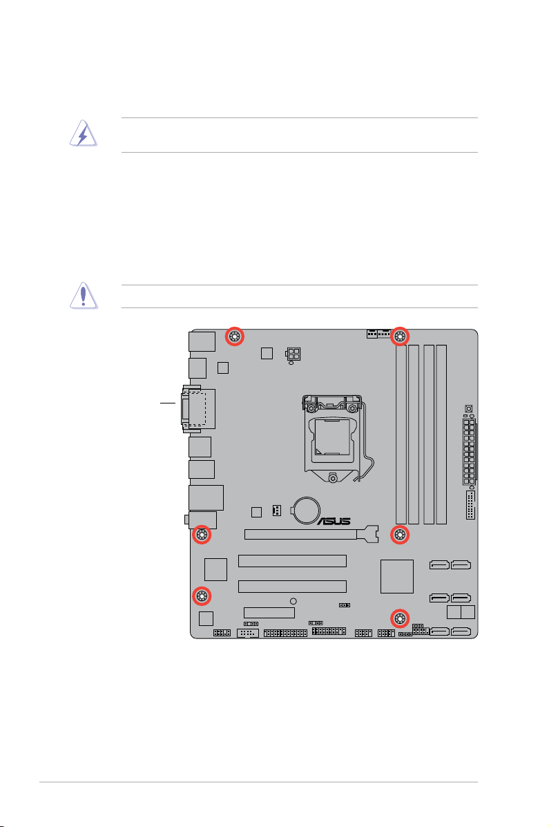
1.5.2 Screw holes
Place six screws into the holes indicated by circles to secure the motherboard to the chassis.
Do not overtighten the screws! Doing so can damage the motherboard.
Place this side towards
the rear of the chassis
1-7Chapter 1: Product introduction
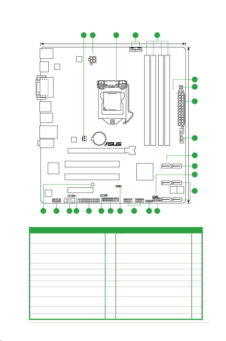
1.5.3 Motherboard layout
1.5.4 Layout contents
Connectors/Jumpers/Slots/LED Page Connectors/Jumpers/Slots/LED Page
1. CPU and chassis fan connectors (4-pin
CPU_FAN, 3-pin CHA_FAN1/2)
1-27 12. Speaker connector (4-pin SPEAKER) 1-28
2. ATX power connectors (24-pin EATXPWR,
4-pin ATX12V)
1-26 13. USB 2.0 connectors (10-1 pin USB56, USB78) 1-30
3. Intel® LGA1155 CPU socket 1-8 14. Intel® ME jumper (3-pin DIS_ME) 1-21
4. DDR3 DIMM slots 1-13 15. TPM connector (20-1 pin TPM) 1-31
5. DRAM LED (DRAM_LED) 1-33 16. Chassis intrusion connector (4-1 pin CHASSIS) 1-26
6. MemOK! switch 1-32 17. LPT connector (26-1 pin LPT) 1-27
7. USB 3.0 connector (20-1 pin USB3_34) 1-30 18. Digital audio connector (4-1 pin SPDIF_OUT) 1-25
8. Intel® B75 Serial ATA 3.0Gb/s connectors (7-pin
SATA3G_1~5 [blue])
1-29 19. Serial port connector (10-1 pin COM1) 1-31
9. Intel® B75 Serial ATA 6.0Gb/s connectors
(7-pin SATA6G_1 [gray])
1-29 20. Front panel audio connector (10-1 pin AAFP) 1-25
10. Clear RTC RAM (3-pin CLRTC) 1-22 21. Onboard LED (SB_PWR) 1-33
11. System panel connector (10-1 pin F_PANEL) 1-28
P8B75-M
PCIEX16
PCI1
PCI2
PCIEX4_1
AAFP
EATXPWR
CPU_FAN
CHA_FAN2
CHA_FAN1
Lithium Cell
CMOS Power
Super
I/O
VIA
VT1708S
EPU
ASM
1442
KBMS
HDMI
64Mb
BIOS
64Mb
BIOS
SB_PWR
CLRTC
DIS_ME
22.6cm(8.9in)
24.4cm(9.6in)
Intel
®
B75
DDR3 DIMM_B1 (64bit, 240-pin module)
DDR3 DIMM_B2 (64bit, 240-pin module)
DDR3 DIMM_A1 (64bit, 240-pin module)
DDR3 DIMM_A2 (64bit, 240-pin module)
SATA3G_5 SATA3G_4
SATA3G_3 SATA3G_2
SATA3G_1 SATA6G_1
AUDIO
USB3_12
USB34
LAN_USB12
SPDIF_OUT
LPT
DVI_VGA
DRAM_LED
MemOK!
LGA1155
USB3_34
F_PANEL
SPEAKER
USB56USB78
TPM
COM1
C
H
A
S
S
IS
RTL
8111F
ATX12V
1 12 3 4
1113 1215161719 1820
6
2
7
8
9
8
10
5
1421
ASUS P8B75-M1-8
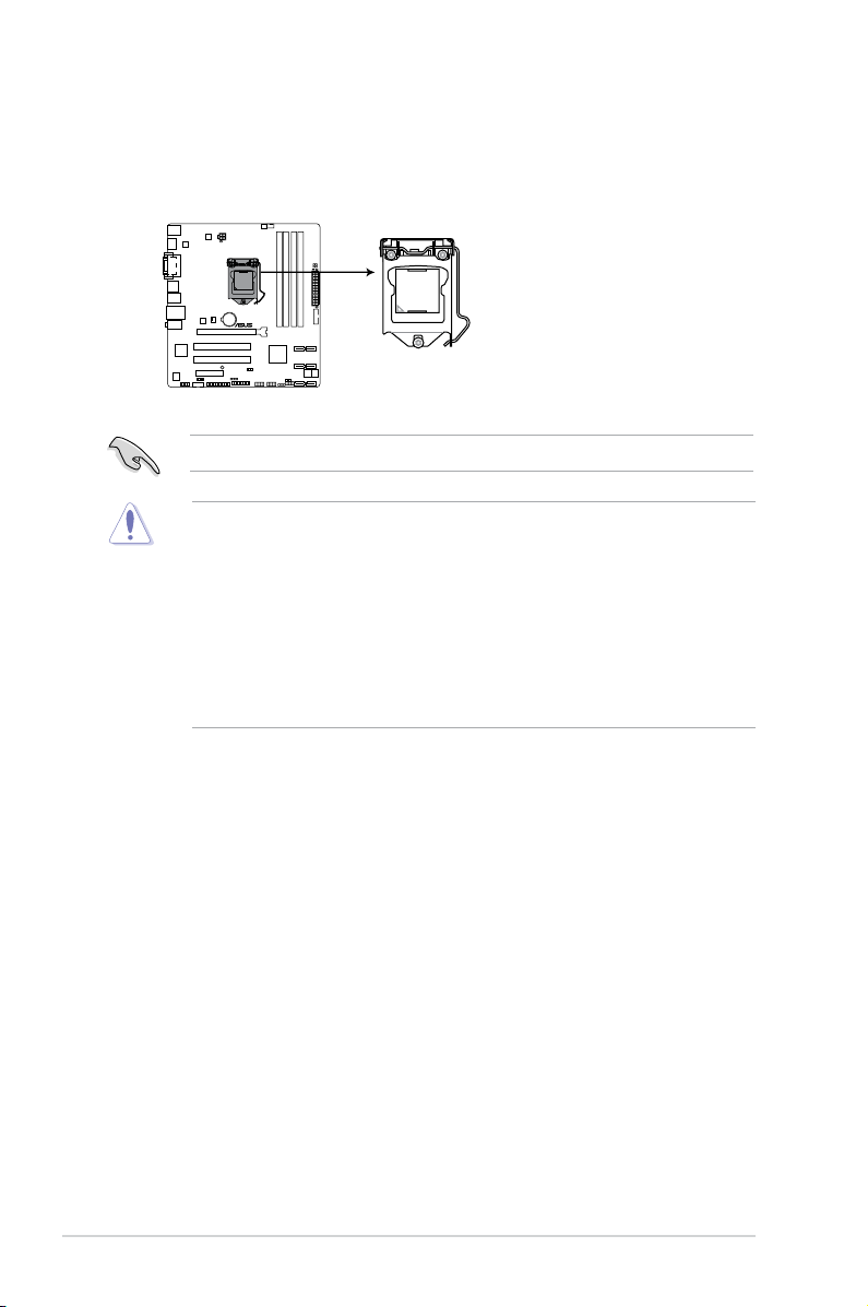
1.6 Central Processing Unit (CPU)
The motherboard comes with a surface mount LGA1155 socket designed for the Intel®
3rd/2nd Generation Core™ i7 / Core™ i5 / Core™ i3, Pentium®, Celeron® processors.
Unplug all power cables before installing the CPU.
• Upon purchase of the motherboard, ensure that the PnP cap is on the socket and the
socket contacts are not bent. Contact your retailer immediately if the PnP cap is missing,
or if you see any damage to the PnP cap/socket contacts/motherboard components.
ASUS will shoulder the cost of repair only if the damage is shipment/transit-related.
• Keep the cap after installing the motherboard. ASUS will process Return Merchandise
Authorization (RMA) requests only if the motherboard comes with the cap on the
LGA1155 socket.
• The product warranty does not cover damage to the socket contacts resulting from
incorrect CPU installation/removal, or misplacement/loss/incorrect removal of the PnP
cap.
Right
P8B75-M
P8B75-M CPU socket LGA1155
1-9Chapter 1: Product introduction
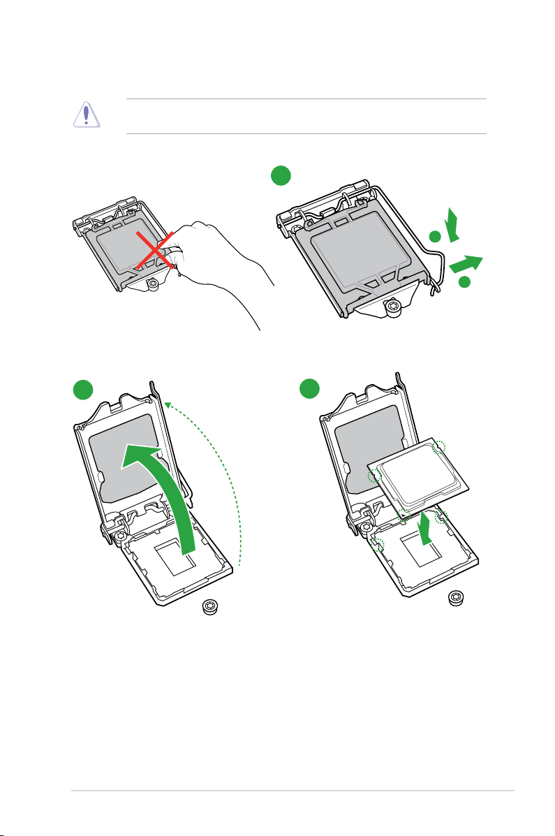
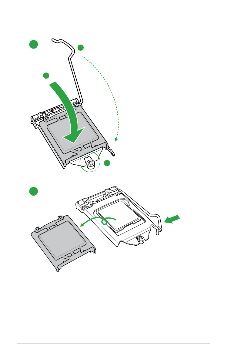
1.6.1 Installing the CPU
1
2
3
The LGA1156 CPU is incompatible with the LGA1155 socket. DO NOT install a LGA1156
CPU on the LGA1155 socket.
A
B
ASUS P8B75-M1-10
A
B
C
5
4
1-11Chapter 1: Product introduction
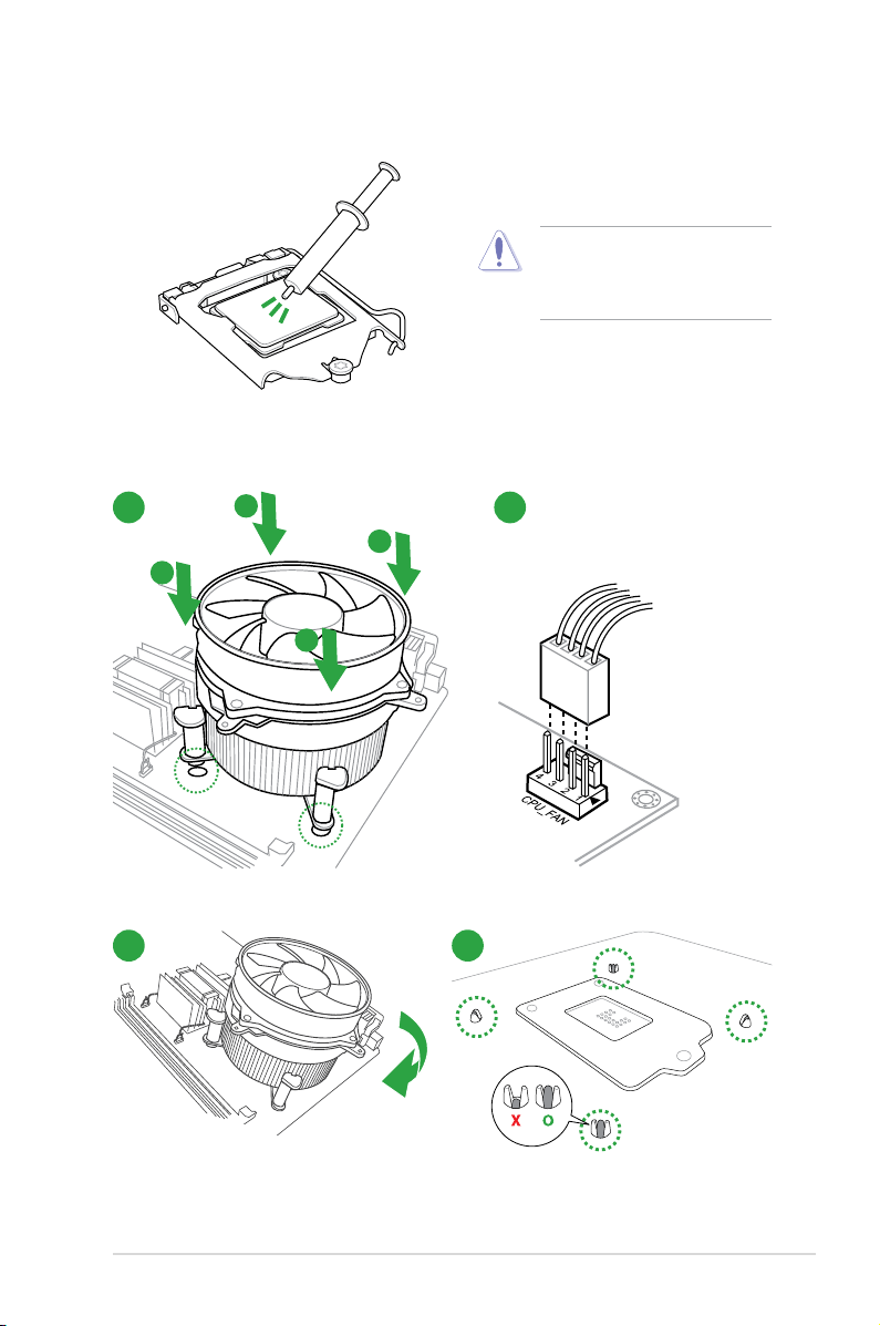
1.6.2 CPU heatsink and fan assembly installation
Apply the Thermal Interface Material
to the CPU heatsink and CPU
before you install the heatsink and
fan if necessary.
To install the CPU heatsink and fan assembly
2
B
A
A
B
3
1
4
ASUS P8B75-M1-12
A
B
B
A
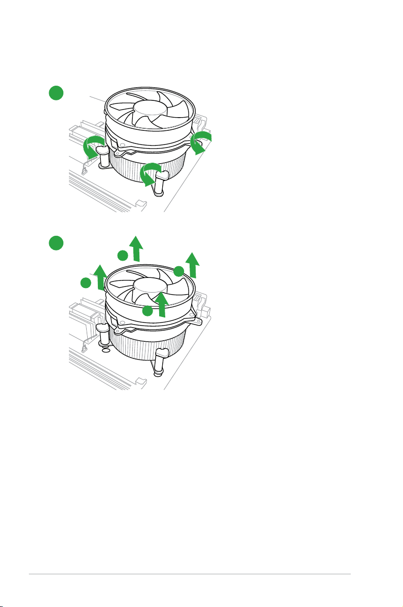
To uninstall the CPU heatsink and fan assembly
2
1
1-13Chapter 1: Product introduction
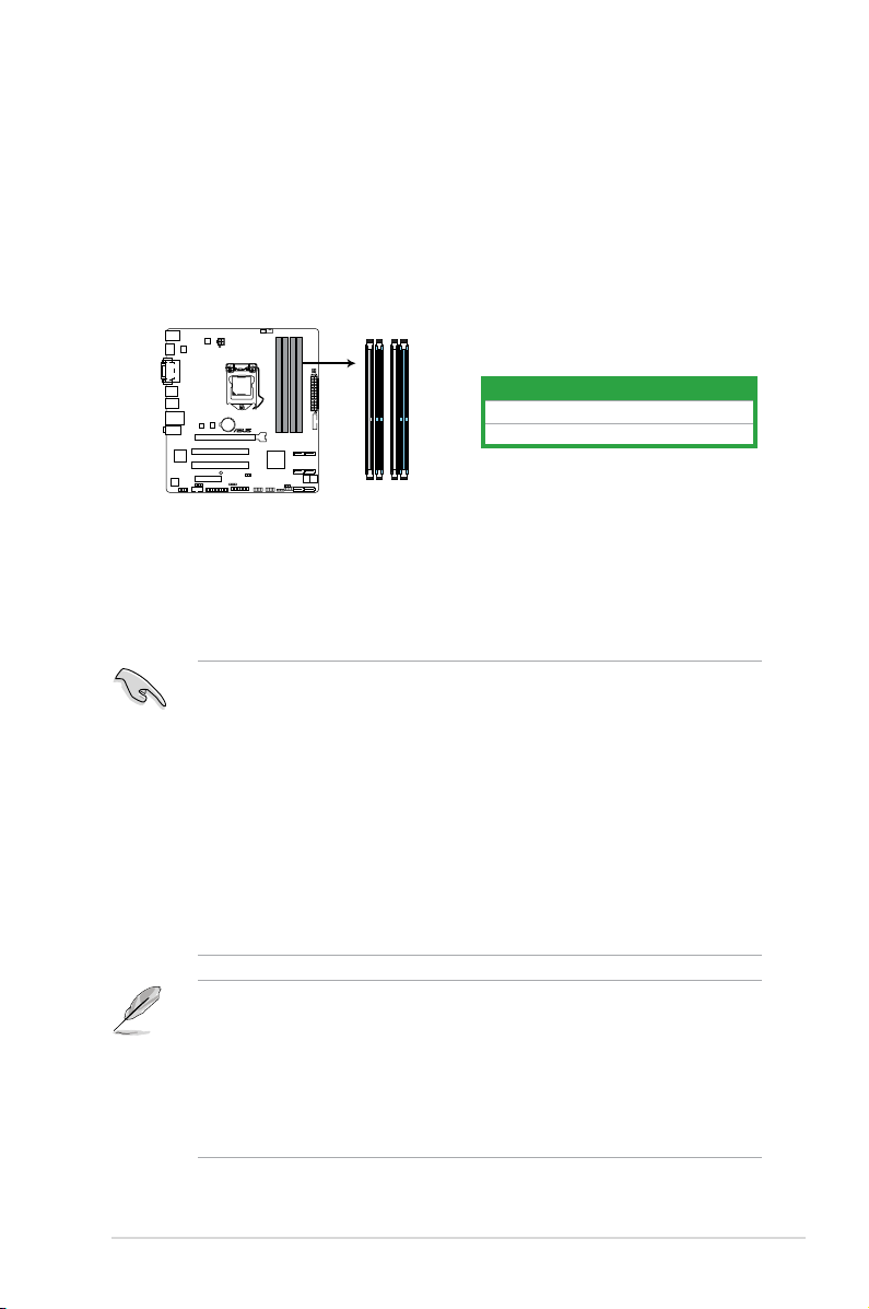
P8B75-M
P8B75-M 240-pin DDR3 DIMM sockets
DIMM_A1
DIMM_A2
DIMM_B1
DIMM_B2
1.7 System memory
1.7.1 Overview
The motherboard comes with four Double Data Rate 3 (DDR3) Dual Inline Memory Modules
(DIMM) sockets. A DDR3 module has the same physical dimensions as a DDR2 DIMM but
is notched differently to prevent installation on a DDR2 DIMM socket. DDR3 modules are
developed for better performance with less power consumption.
The gure illustrates the location of the DDR3 DIMM sockets:
Channel Sockets
Channel A DIMM_A1 and DIMM_A2
Channel B DIMM_B1 and DIMM_B2
1.7.2 Memory congurations
You may install 1GB, 2GB, 4GB, and 8GB unbuffered non-ECC DDR3 DIMMs into the DIMM
sockets.
• The default memory operation frequency is dependent on its Serial Presence Detect
(SPD), which is the standard way of accessing information from a memory module.
Under the default state, some memory modules for overclocking may operate at a
lower frequency than the vendor-marked value. To operate at the vendor-marked or at a
higher frequency, refer to section 2.4 Ai Tweaker menu for manual memory frequency
adjustment.
• For system stability, use a more efcient memory cooling system to support a full
memory load (4 DIMMs) or overclocking condition.
• You may install varying memory sizes in Channel A and Channel B. The system maps
the total size of the lower-sized channel for the dual-channel conguration. Any excess
memory from the higher-sized channel is then mapped for single-channel operation.
• Always install DIMMs with the same CAS latency. For optimum compatibility, we
recommend that you obtain memory modules from the same vendor.
• Due to the memory address limitation on 32-bit Windows
®
OS, when you install 4GB
or more memory on the motherboard, the actual usable memory for the OS can be
about 3GB or less. For effective use of memory, we recommend that you do any of the
following:
- Use a maximum of 3GB system memory if you are using a 32-bit Windows
®
OS.
- Install a 64-bit Windows® OS when you want to install 4GB or more on the
motherboard.
• This motherboard does not support DIMMs made up of 512Mb (64MB) chips or less.
ASUS P8B75-M1-14
P8B75-M Motherboard Qualied Vendors Lists (QVL)
DDR3-2400 MHz capability
Vendors Part No. Size
SS/DSChip
Brand
Chip
NO.
Timing Voltage
DIMM socket support (Optional)
2 DIMMs 4 DIMMs
G.SKILL
F3-19200CL11Q16GBZHD(XMP1.3)
16GB(4 x4GB) DS - - 11-11-11-31 1.65V • •
G.SKILL
F3-19200CL9D4GBPIS(XMP)
4GB(2x 2GB) DS - - 9-11-9-28 1.65V • •
GEIL GET34GB2400C9DC(XMP) 2GB DS - - 9-11-9-27 1.65V • •
Transcend
TX2400KLU4GK(374243)(XMP)
4GB(2x 2GB) DS - - 9 1.65V • •
DDR3-2200 MHz capability
Vendors Part No. Size
SS/DSChip
Brand
Chip
NO.
Timing Voltage
DIMM socket support (Optional)
2 DIMMs 4 DIMMs
G.SKILL
F3-17600CL8D4GBPS(XMP)
4GB(2 x2GB) DS - - 8-8-8-24 1.65V •
Kingmax
FLKE85FB8KHAEEIH(XMP)
4GB(2x 2GB) DS - - - 1.5V-1.7v • •
DDR3-2133 MHz capability
Vendors Part No. Size
SS/DSChip
Brand
Chip
NO.
Timing Voltage
DIMM socket support
(Optional)
2 DIMMs 4 DIMMs
CORSAIR CMT16GX3M4X2133C9(XMP 1.3) 16GB(4 x4GB) DS - - 9-11-10-27 1.50V • •
CORSAIR CMT4GX3M2A2133C9(XMP) 4GB(2x 2GB) DS - - 9-10-9-24 1.65V • •
CORSAIR CMT4GX3M2B2133C9(XMP) 4GB(2x 2GB) DS - - 9-10-9-27 1.50V • •
GEIL GE34GB2133C9DC(XMP) 2GB DS - - 9-9-9-28 1.65V • •
GEIL GU34GB2133C9DC(XMP) 4GB(2 x 2GB) DS - - 9-9-9-28 1.65V • •
KINGSTON KHX2133C9AD3T1K2/4GX(XMP) 4GB(2x 2GB ) DS - - - 1.65V • •
KINGSTON KHX2133C9AD3T1K4/8GX(XMP) 8GB(4 x 2GB) DS - - 9-11-9-27 1.65V • •
KINGSTON
KHX2133C9AD3T1FK4/
8GX(XMP)
8GB(4x 2GB) DS - - - 1.65V • •
PATRIOT PGD38G2133C11K(XMP) 16GB(4GB x4) DS - - 11-11-11-30 1.65V • •
DDR3-2000 MHz capability
Vendors Part No. Size
SS/DSChip
Brand
Chip NO. Timing Voltage
DIMM socket support
(Optional)
2 DIMMs 4 DIMMs
CORSAIR CMZ4GX3M2A2000C10(XMP) 4GB(2 x 2GB) SS - - 10-10-10-27 1.50V • •
G.SKILL F3-16000CL6T-6GBPIS(XMP) 6GB (3x 2GB ) DS - - 6-9-6-24 1.65V • •
GEIL GUP34GB2000C9DC(XMP) 4GB(2 x 2GB) DS - - 9-9-9-28 1.65V • •
KINGSTON KHX2000C9AD3T1K2/4GX(XMP) 4GB(2x 2GB ) DS - - - 1.65V • •
KINGSTON KHX2000C9AD3W1K2/4GX(XMP) 4GB(2x 2GB ) DS - - - 1.65V • •
KINGSTON KHX2000C9AD3T1K2/4GX(XMP) 4GB(2 x 2GB) DS - - 9 1.65V • •
KINGSTON KHX2000C9AD3W1K3/6GX(XMP) 6GB(3x 2GB ) DS - - - 1.65V • •
Asint SLA302G08-ML2HB(XMP) 4GB DS HYNIX
H5TQ2G83BFR
H9C
- - • •
DDR3-1866 MHz capability
Vendors Part No. Size
SS/DSChip
Brand
Chip
NO.
Timing Voltage
DIMM socket support
(Optional)
2 DIMMs 4 DIMMs
CORSAIR CMT4GX3M2A1866C9(XMP) 4GB(2 x 2GB) DS - - 9-9-9-24 1.65V • •
CORSAIR CMT6GX3MA1866C9(XMP) 6GB(3 x 2GB) DS - - 9-9-9-24 1.65V • •
CORSAIR CMZ8GX3M2A1866C9(XMP) 8GB(2 x 4GB) DS - - 9-10-9-27 1.50V • •
G.SKILL F3-14900CL9Q-16GBZL(XMP1.3) 16GB(4 x4GB) DS - - 9-10-9-28 1.5V • •
G.SKILL
F3-14900CL10Q264GBZLD(XMP1.3)
64GB(8GBx 8) DS - - 10-11-10-30 1.5V • •
G.SKILL F3-14900CL9D-8GBXL(XMP) 8GB(2 x 4GB) DS - - 9-10-9-28 1.5V • •
G.SKILL F3-14900CL9Q-8GBXL(XMP) 8GB(2GBx4) DS - - 9-9-9-24 1.6V • •
KINGSTON KHX1866C9D3T1K3/3GX(XMP) 3GB(3 x 1GB) SS - - - 1.65V • •
KINGSTON KHX1866C9D3K4/16GX(XMP) 16GB 4GB x4 ) DS - - - 1.65V • •
KINGSTON KHX1866C9D3T1K3/6GX(XMP) 6GB(3 x 2GB) DS - - - 1.65V • •
KINGSTON KHX1866C11D3P1K2/8G 8GB(4GB x 2) DS - - - 1.5V • •
 Loading...