How it Works
Log In / Sign Up
Buy Points
How it Works
FAQ
Contact Us
Questions and Suggestions
Users
Asus
Loading...
E
E7780
E7805
E7809
E7811
E7814
E7832
E7847
E790
E7926
2
E7938
E7959
E7965
E7973
E7997
E8025
E8026
E806 CRW-2410S
E8083
E810
25
E810-B0354
E8198
E8316
E8333
E8445
E8468
E8476
E8521
E8530
E8546
E8558
e8581
E8587
E8699
E8711
E8770
E8803
E8815
E8837
E8850
E8851
E8853
E8856
E8886
E8887
e8909
E8923
E8989
E8991
E8994
E8PNE762H
E900 G4
E9019
E9022
E9029
E9036
E9042
E9045
E9071
E9088
E9092
E9095
E9100
E9105
E9113
E9131
E9141
E9142
E915
E9152
E9159
E9174
E9184
E9188
E9192
E9293
E9295
E9331
E9367
E9378
E9380
E9385
E9389
E9394
E9396
E9399
E9429
E9439
e9444
E9472
E9481
e9505
e9510
E9512
E9515
E9526
E9537
E9550
E9561
E9564
E9584
Loading...
Loading...
Nothing found
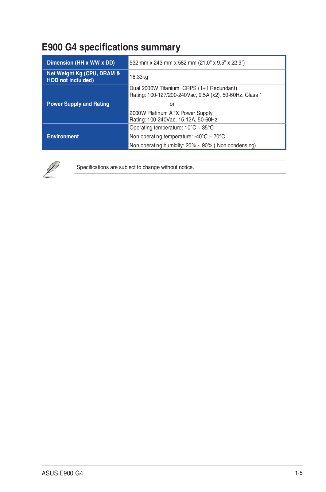
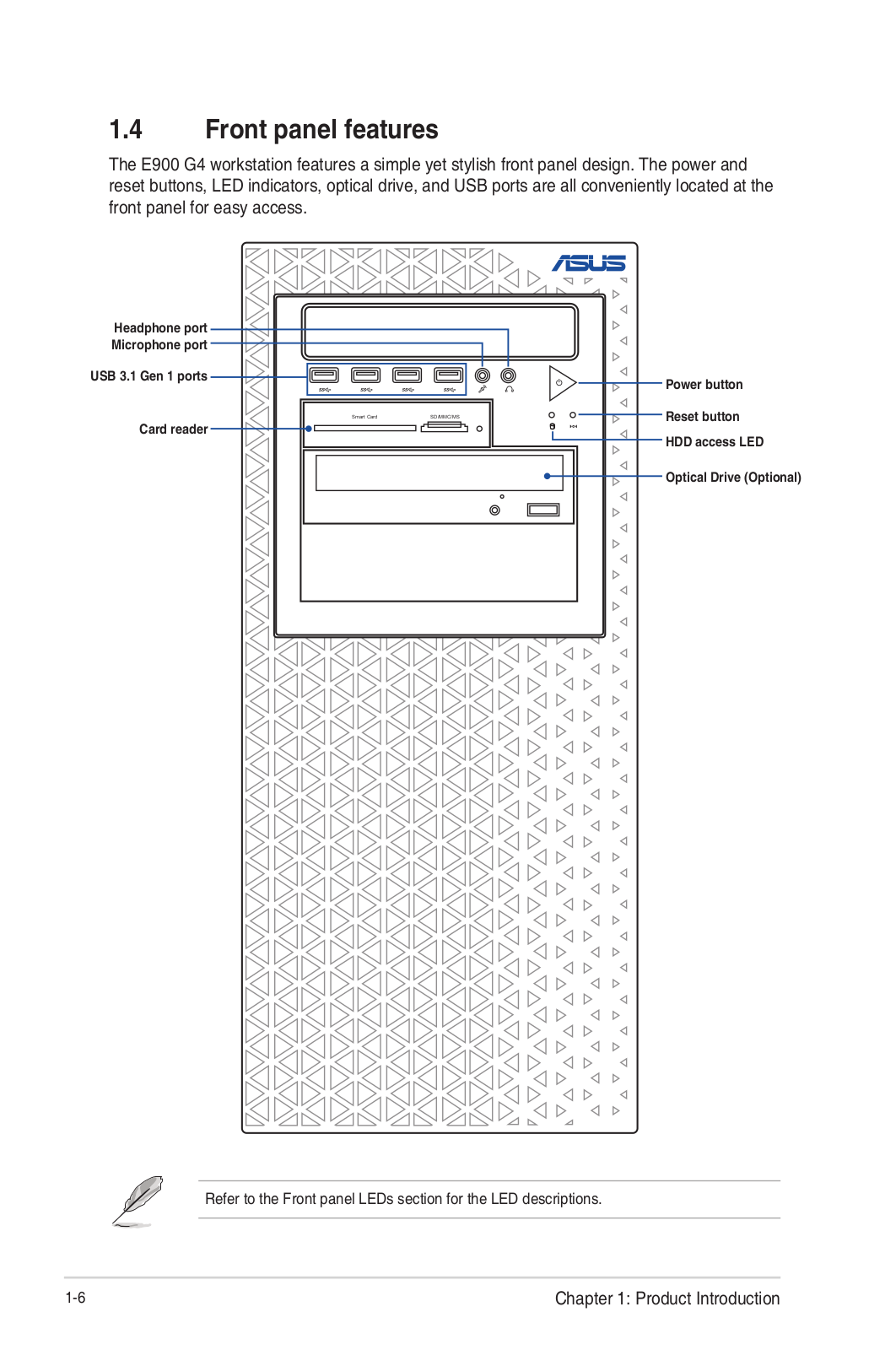
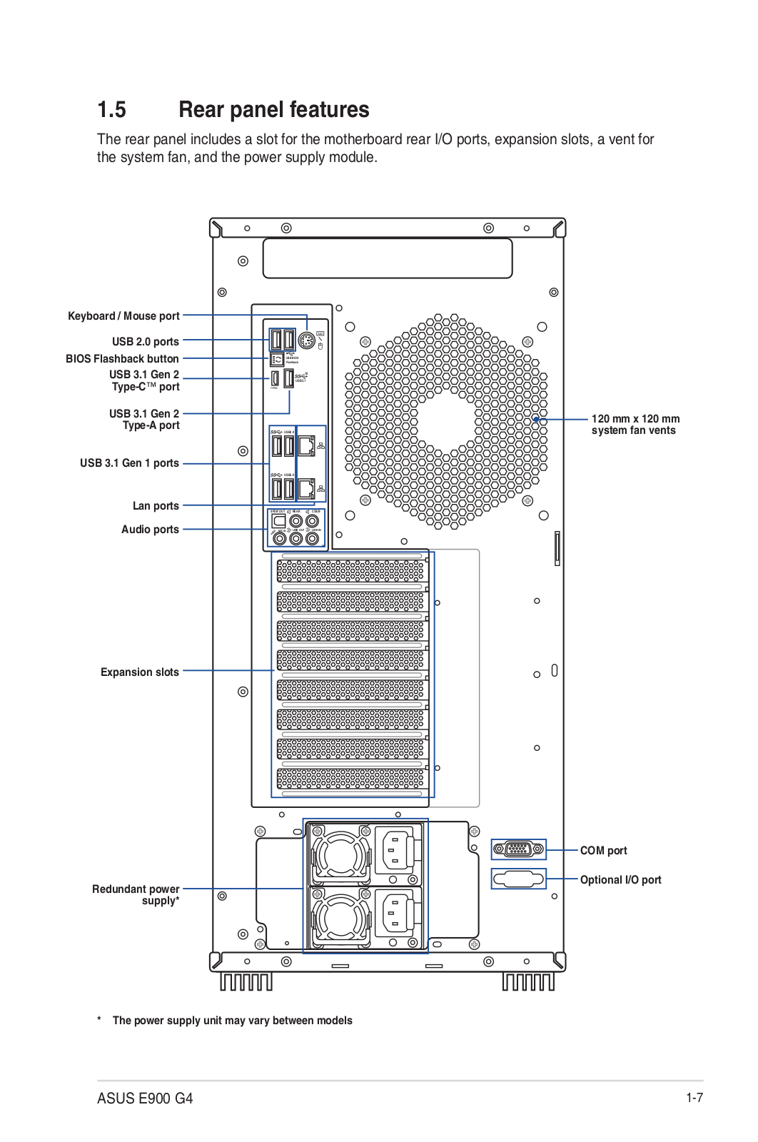
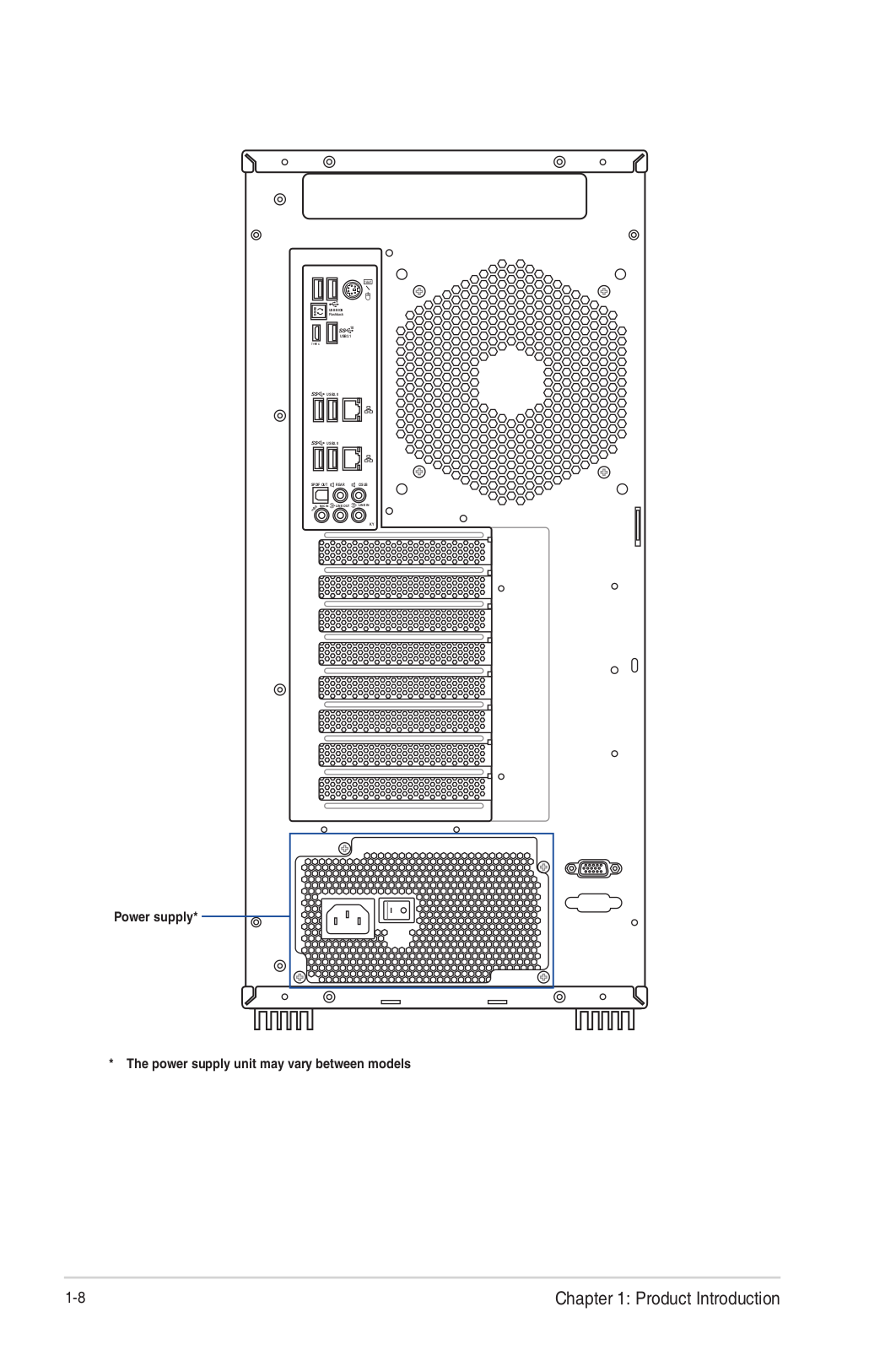
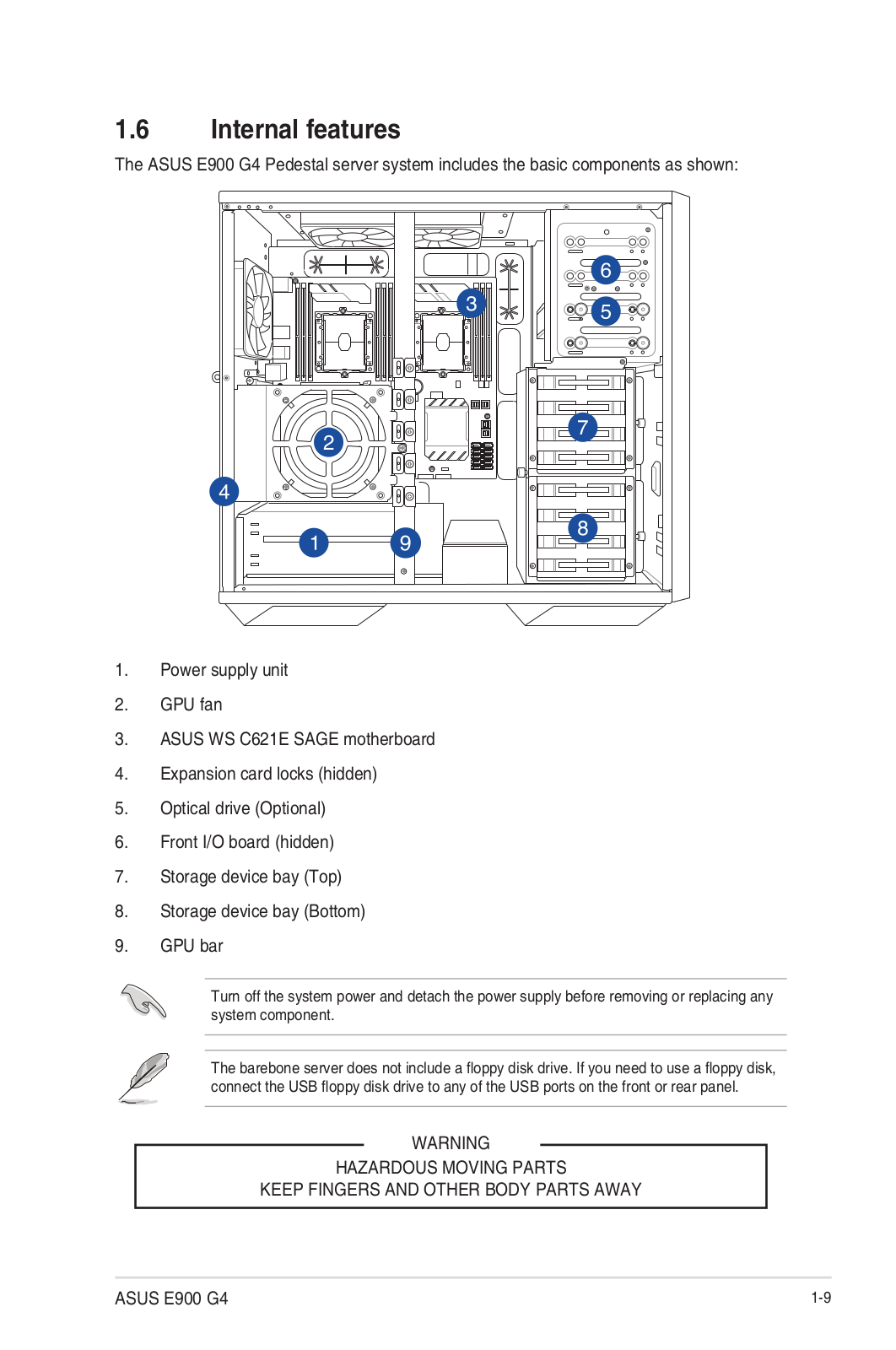
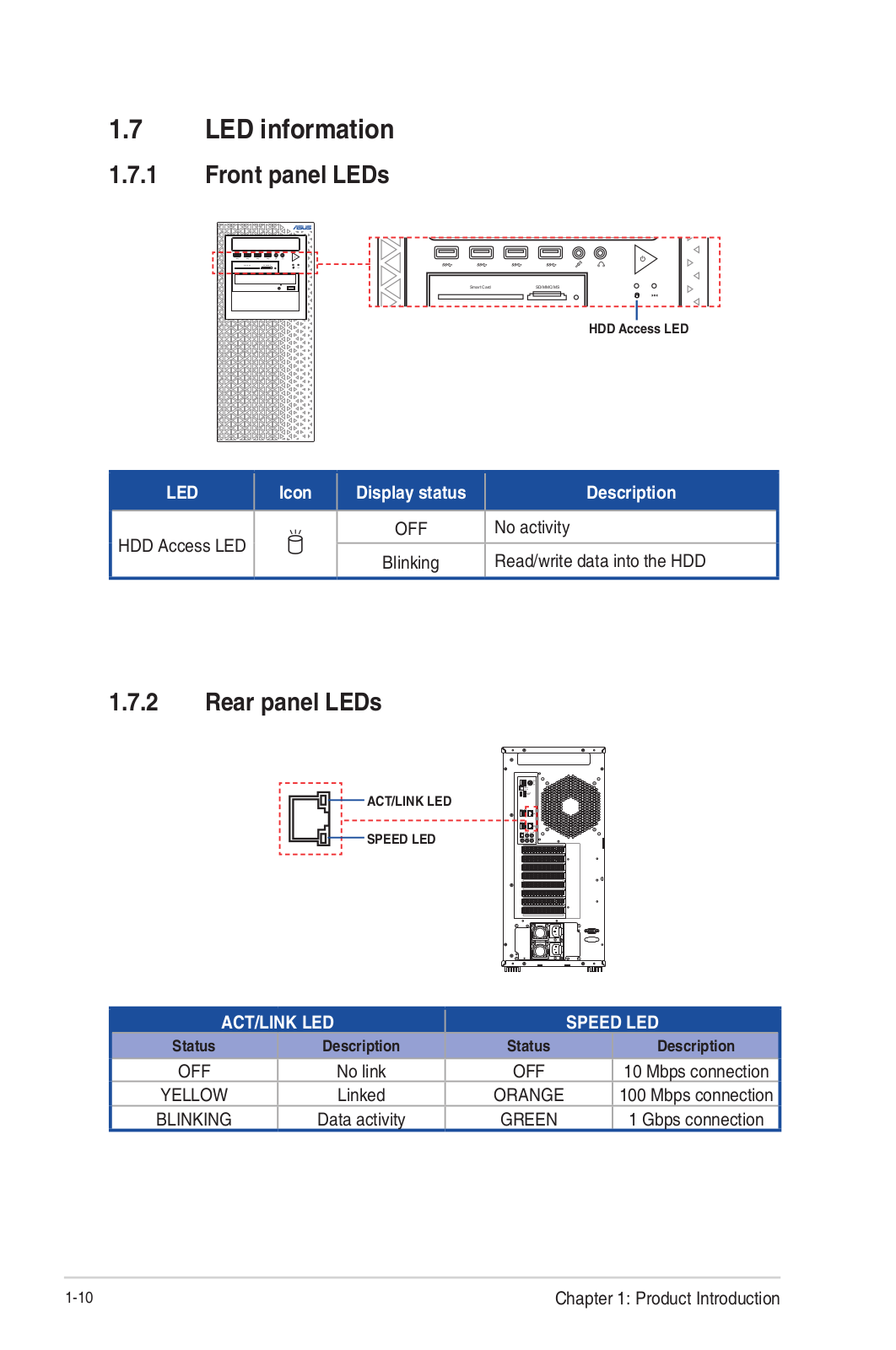
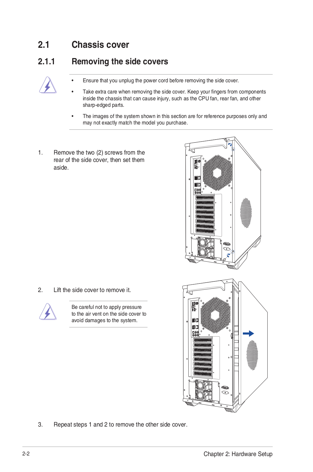
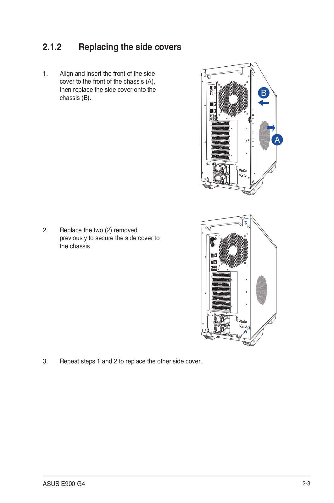
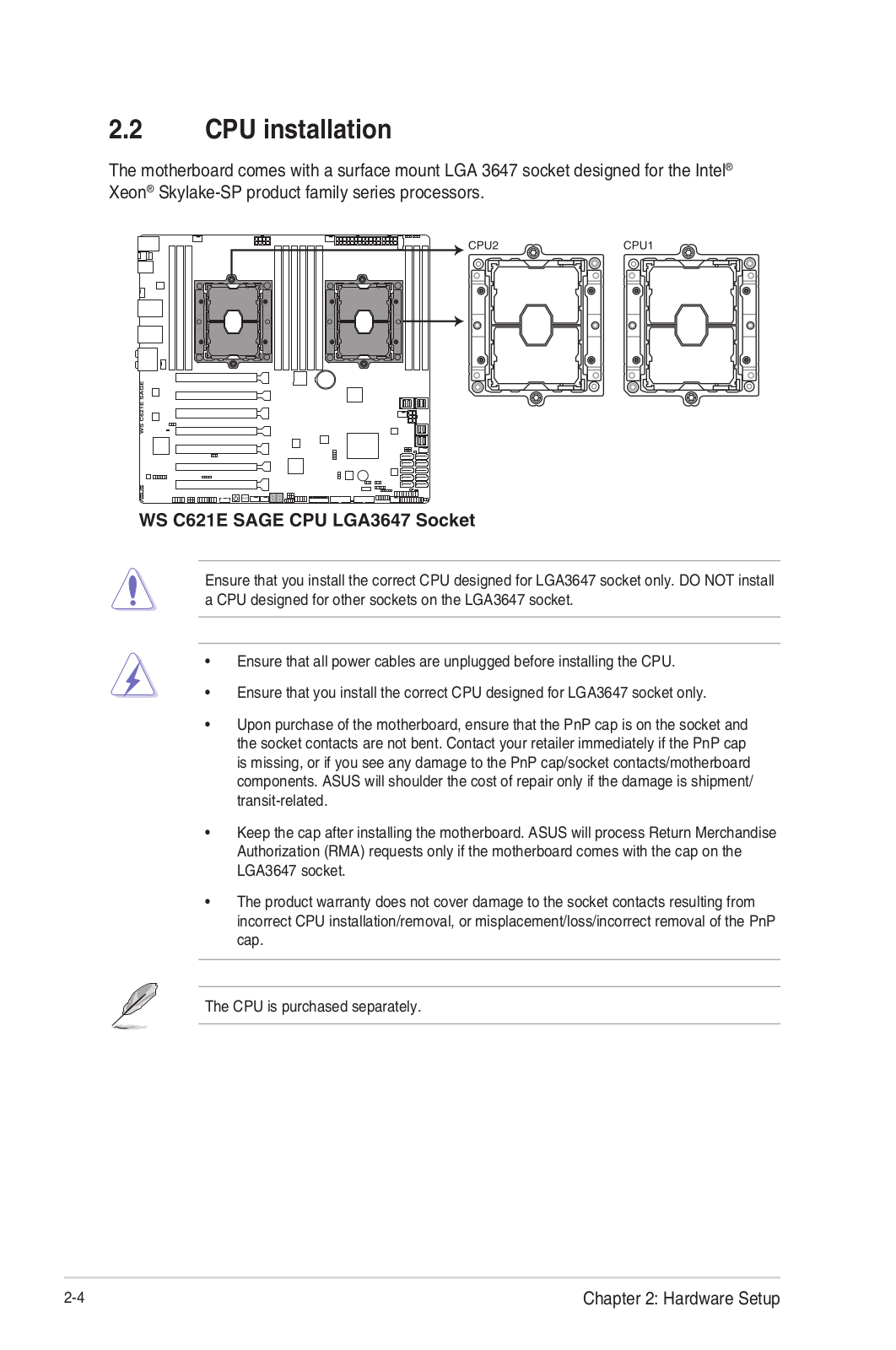
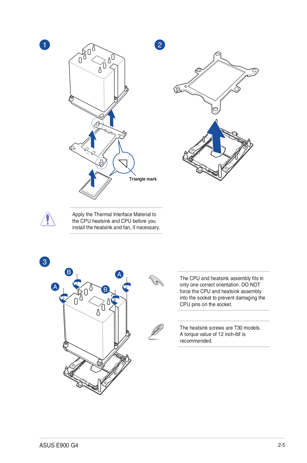
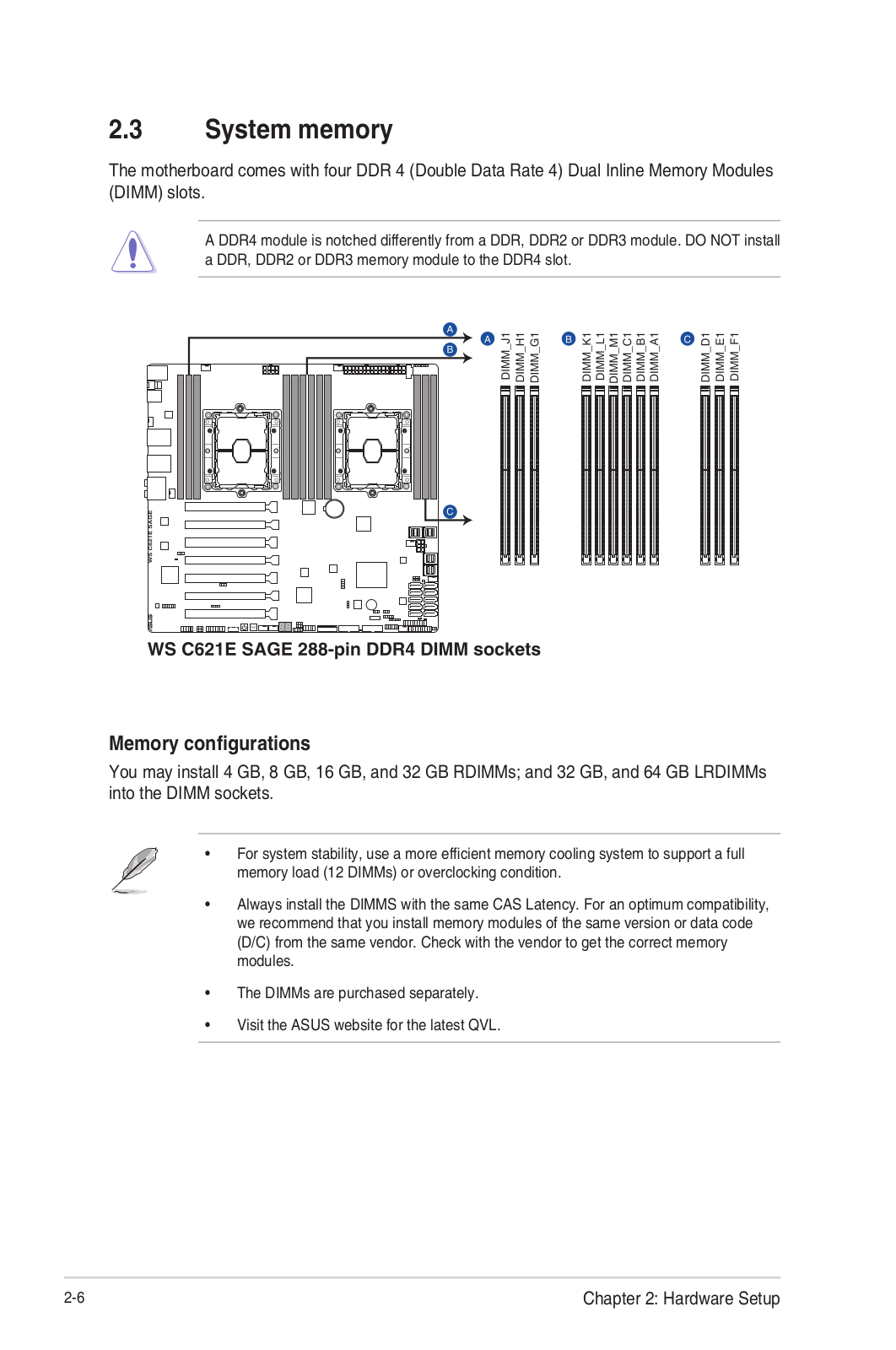
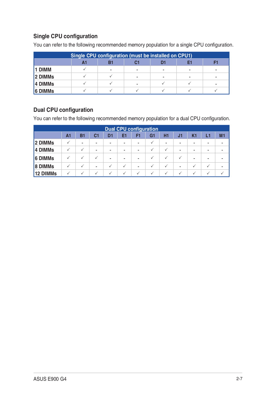
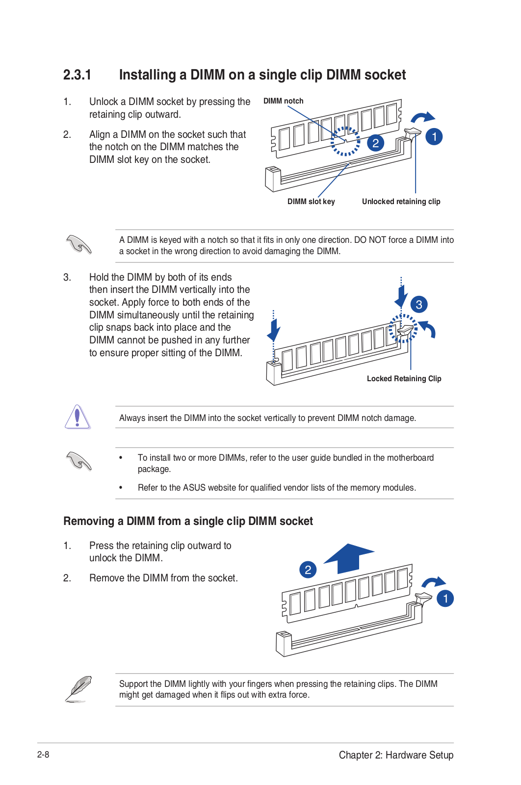
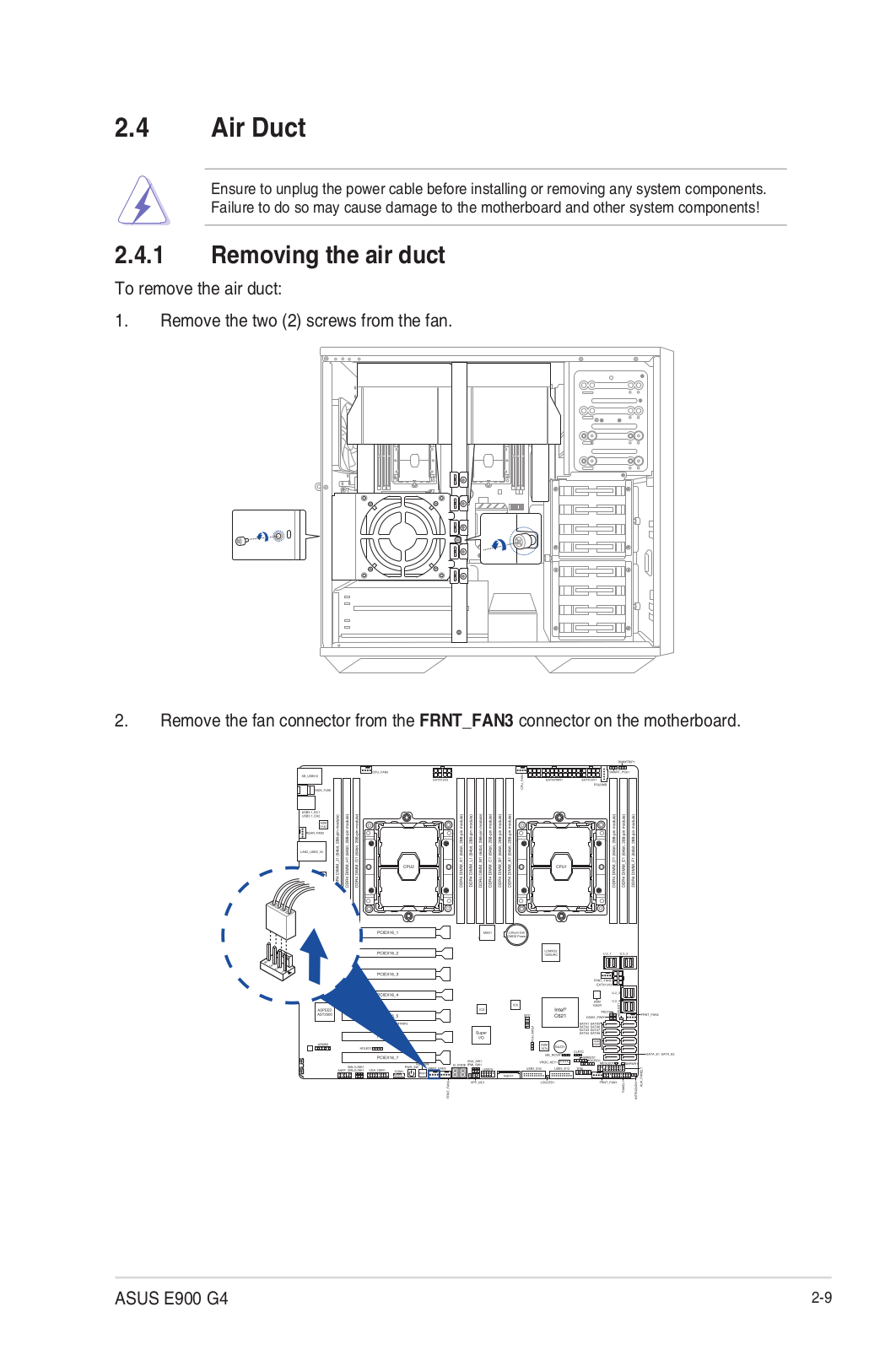
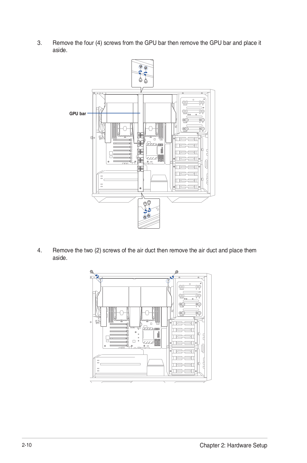
E900 G4
Users guide
146 pgs
12.08 Mb
0
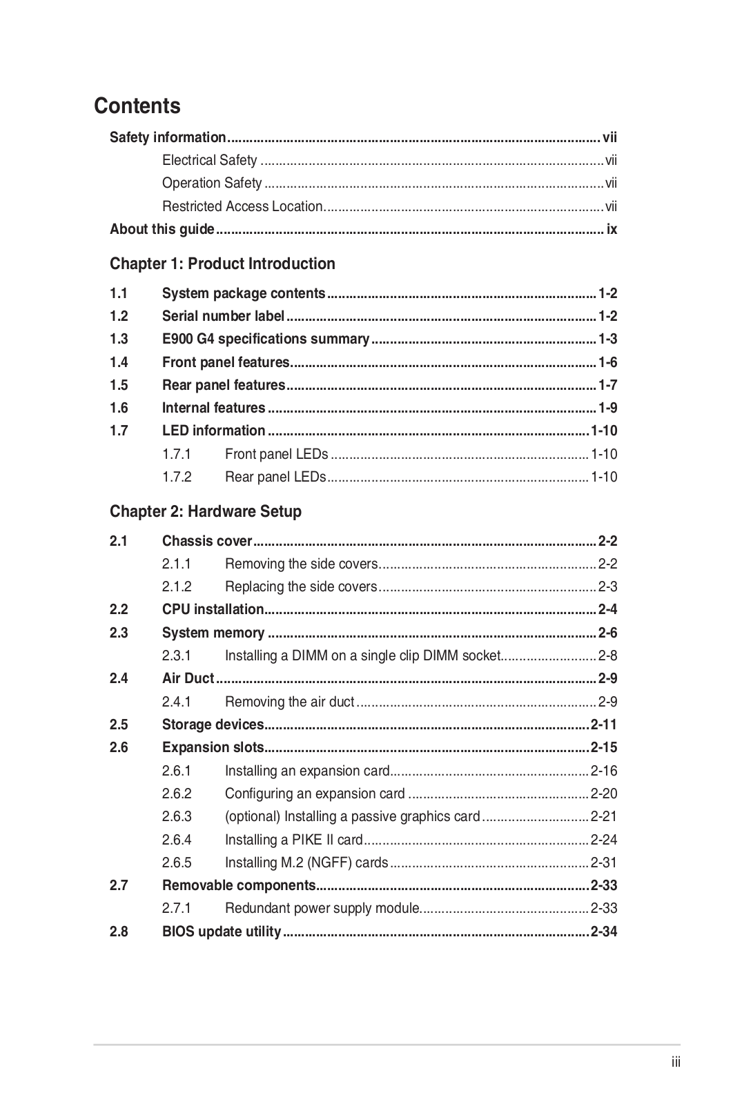
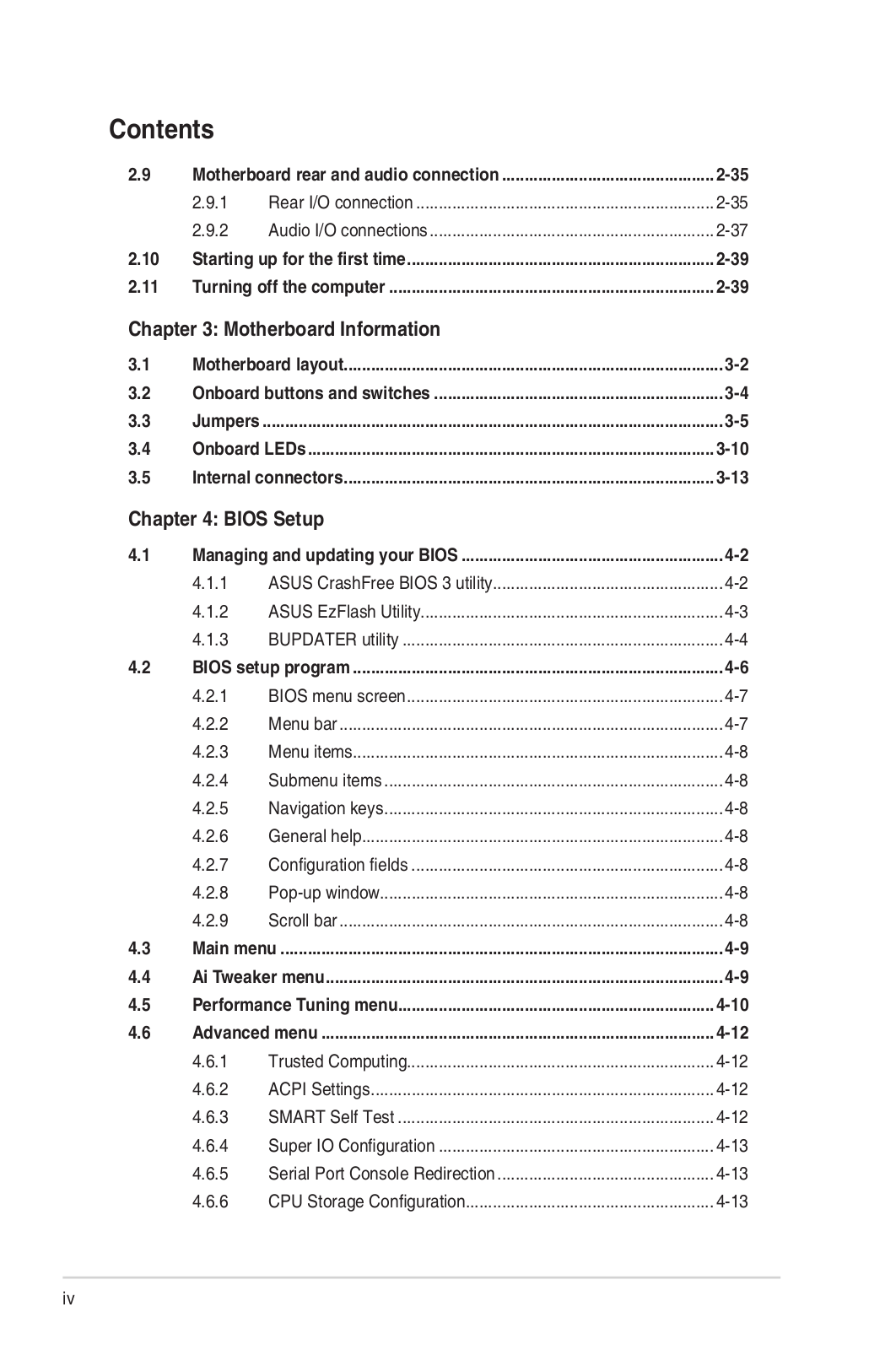
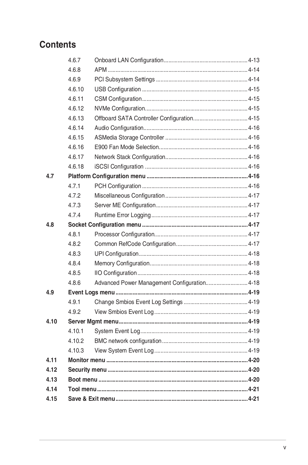
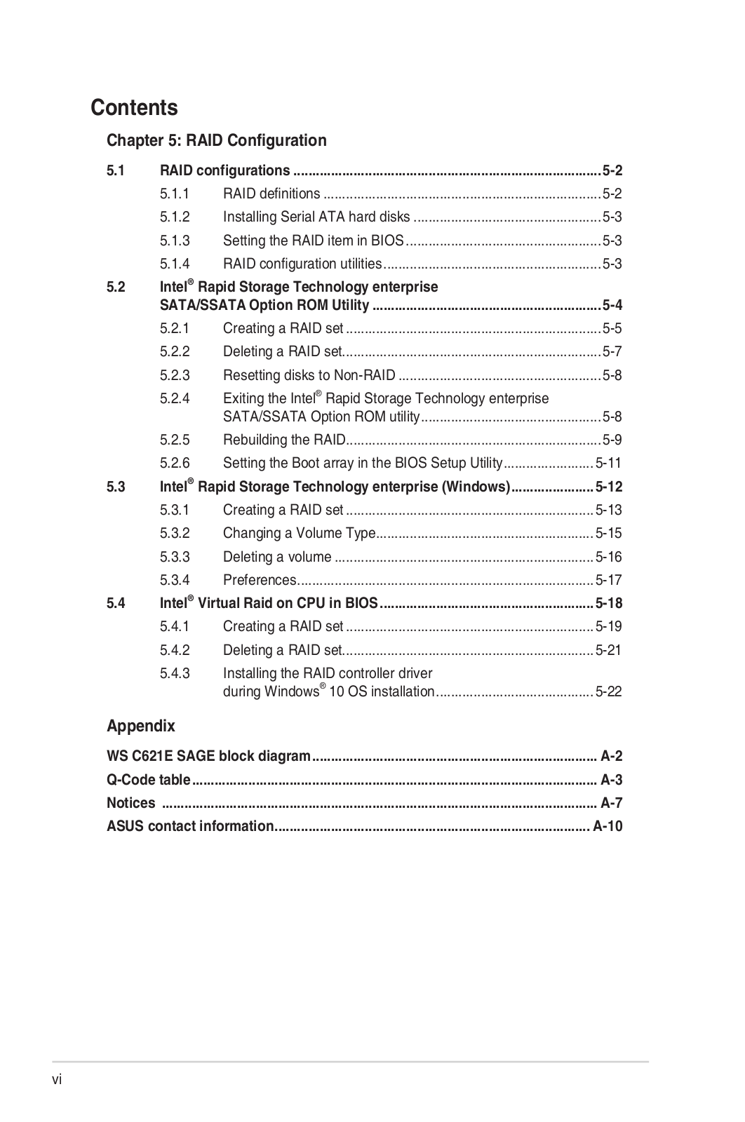
Table of contents
Loading...
Asus E900 G4 Users guide
...
Asus Users guide
Download
Specifications and Main Features
Frequently Asked Questions
User Manual
Download
Loading...
+
hidden pages
Unhide
You need points to download manuals.
1 point = 1 manual.
You can buy points or you can get point for every manual you upload.
Buy points
Upload your manuals
 Loading...