

Page 1

MAXIMUS V
FORMULA
Series
Motherboard
Page 2

E7295
First Edition
May 2012
Copyright © 2012 ASUSTeK COMPUTER INC. All Rights Reserved.
No part of this manual, including the products and software described in it, may be reproduced,
transmitted, transcribed, stored in a retrieval system, or translated into any language in any form or by any
means, except documentation kept by the purchaser for backup purposes, without the express written
permission of ASUSTeK COMPUTER INC. (“ASUS”).
Product warranty or service will not be extended if: (1) the product is repaired, modied or altered, unless
such repair, modication of alteration is authorized in writing by ASUS; or (2) the serial number of the
product is defaced or missing.
ASUS PROVIDES THIS MANUAL “AS IS” WITHOUT WARRANTY OF ANY KIND, EITHER EXPRESS
OR IMPLIED, INCLUDING BUT NOT LIMITED TO THE IMPLIED WARRANTIES OR CONDITIONS OF
MERCHANTABILITY OR FITNESS FOR A PARTICULAR PURPOSE. IN NO EVENT SHALL ASUS, ITS
DIRECTORS, OFFICERS, EMPLOYEES OR AGENTS BE LIABLE FOR ANY INDIRECT, SPECIAL,
INCIDENTAL, OR CONSEQUENTIAL DAMAGES (INCLUDING DAMAGES FOR LOSS OF PROFITS,
LOSS OF BUSINESS, LOSS OF USE OR DATA, INTERRUPTION OF BUSINESS AND THE LIKE),
EVEN IF ASUS HAS BEEN ADVISED OF THE POSSIBILITY OF SUCH DAMAGES ARISING FROM ANY
DEFECT OR ERROR IN THIS MANUAL OR PRODUCT.
SPECIFICATIONS AND INFORMATION CONTAINED IN THIS MANUAL ARE FURNISHED FOR
INFORMATIONAL USE ONLY, AND ARE SUBJECT TO CHANGE AT ANY TIME WITHOUT NOTICE,
AND SHOULD NOT BE CONSTRUED AS A COMMITMENT BY ASUS. ASUS ASSUMES NO
RESPONSIBILITY OR LIABILITY FOR ANY ERRORS OR INACCURACIES THAT MAY APPEAR IN THIS
MANUAL, INCLUDING THE PRODUCTS AND SOFTWARE DESCRIBED IN IT.
Products and corporate names appearing in this manual may or may not be registered trademarks or
copyrights of their respective companies, and are used only for identication or explanation and to the
owners’ benet, without intent to infringe.
Offer to Provide Source Code of Certain Software
This product contains copyrighted software that is licensed under the General Public License (“GPL”),
under the Lesser General Public License Version (“LGPL”) and/or other Free Open Source Software
Licenses. Such software in this product is distributed without any warranty to the extent permitted by the
applicable law. Copies of these licenses are included in this product.
Where the applicable license entitles you to the source code of such software and/or other additional data,
you may obtain it for a period of three years after our last shipment of the product, either
(1) for free by downloading it from http://support.asus.com/download
or
(2) for the cost of reproduction and shipment, which is dependent on the preferred carrier and the location
where you want to have it shipped to, by sending a request to:
ASUSTeK Computer Inc.
Legal Compliance Dept.
15 Li Te Rd.,
Beitou, Taipei 112
Taiwan
In your request please provide the name, model number and version, as stated in the About Box of the
product for which you wish to obtain the corresponding source code and your contact details so that we
can coordinate the terms and cost of shipment with you.
The source code will be distributed WITHOUT ANY WARRANTY and licensed under the same license as
the corresponding binary/object code.
This offer is valid to anyone in receipt of this information.
ASUSTeK is eager to duly provide complete source code as required under various Free Open Source
Software licenses. If however you encounter any problems in obtaining the full corresponding source
code we would be much obliged if you give us a notication to the email address gpl@asus.com, stating
the product and describing the problem (please DO NOT send large attachments such as source code
archives, etc. to this email address).
ii
Page 3

Contents
Safety information ..................................................................................................... vii
About this guide ....................................................................................................... viii
MAXIMUS V FORMULA Series specications summary ......................................... x
ROG ThunderFX specications summary .............................................................. xv
Package contents ..................................................................................................... xvi
Installation tools and components ........................................................................ xvii
Chapter 1: Product introduction 1-1
1.1 Special features..........................................................................................1-1
1.1.1 Product highlights
1.1.2
1.1.3
1.1.4
1.1.5
1.2 Motherboard overview ...............................................................................
1.2.1 Before you proceed .....................................................................
1.2.2 Motherboard layout .....................................................................
1.2.3 Central Processing Unit (CPU) ...................................................
1.2.4 System memory ........................................................................
1.2.5 Expansion slots .........................................................................
1.2.6 Onboard buttons and switches
1.2.7 Jumpers ....................................................................................
1.2.8 Onboard LEDs ..........................................................................
1.2.9 Internal connectors
1.2.10 Fusion Thermo ..........................................................................
ROG unique gaming features .....................................................1-2
ROG Intelligent Performance & Overclocking features ............... 1-2
ASUS special features ................................................................1-4
ROG-rich bundled software......................................................... 1-4
........................................................................ 1-1
.................................................. 1-24
.................................................................... 1-36
1-6
1-6
1-7
1-9
1-10
1-21
1-26
1-27
1-47
Chapter 2: Basic Installation 2-1
2.1 Building your PC system...........................................................................2-1
2.1.1 Motherboard installation ..............................................................
2.1.2 CPU installation
2.1.3 CPU heatsink and fan assembly installation ...............................
2.1.4 DIMM installation
2.1.5 ATX Power connection ................................................................
2.1.6 SATA device connection ..............................................................
2.1.7 Front I/O Connector ..................................................................
2.1.8 Expansion Card installation
2.1.9 mPCIe Combo installation
........................................................................... 2-4
......................................................................... 2-7
....................................................... 2-11
......................................................... 2-12
2-1
2-5
2-8
2-9
2-10
iii
Page 4

2.2 BIOS update utility ................................................................................... 2-19
2.2.1 USB BIOS Flashback ................................................................
2.3 Motherboard rear and audio connections .............................................
2.3.1 Rear I/O connection ..................................................................
2.3.2 Audio I/O connections ...............................................................
2.4 Starting up for the rst time ....................................................................
2.5 Turning off the computer .........................................................................
2-19
2-20
2-20
2-21
2-25
2-25
Chapter 3: BIOS setup 3-1
3.1 Knowing BIOS ............................................................................................3-1
3.2 BIOS setup program ..................................................................................
3.2.1 EZ Mode
3.2.2 Advanced Mode ..........................................................................
3.3 Extreme Tweaker menu .............................................................................
3.4 Main menu ................................................................................................
3.5 Advanced menu .......................................................................................
3.5.1 CPU Conguration ....................................................................
3.5.2 PCH Conguration ....................................................................
3.5.3 SATA Conguration ...................................................................
3.5.4 System Agent Conguration
3.5.5 USB Conguration ....................................................................
3.5.6 Onboard Devices Conguration ................................................
3.5.7 APM ..........................................................................................
3.5.8 Network Stack ...........................................................................
3.6 Monitor menu ...........................................................................................
3.7 Boot menu ................................................................................................
3.8 Tools menu ...............................................................................................
3.8.1 ASUS EZ Flash 2 Utility ............................................................
3.8.2 ASUS O.C. Prole .....................................................................
3.8.3 ASUS SPD Information .............................................................
3.8.4 GO Button File ..........................................................................
3.9 Exit menu ..................................................................................................
3.10 Updating BIOS ..........................................................................................
3.10.1 ASUS Update ............................................................................
3.10.2 ASUS EZ Flash 2 ......................................................................
3.10.3 ASUS CrashFree BIOS 3 ..........................................................
3.10.4 ASUS BIOS Updater .................................................................
...................................................................................... 3-3
...................................................... 3-27
3-2
3-4
3-6
3-19
3-22
3-23
3-25
3-26
3-28
3-30
3-32
3-33
3-34
3-37
3-39
3-39
3-39
3-40
3-41
3-42
3-43
3-43
3-46
3-47
3-48
iv
Page 5

Chapter 4: Software support 4-1
4.1 Installing an operating system .................................................................4-1
4.2 Support DVD information ..........................................................................
4.2.1 Running the support DVD ...........................................................
4.2.2 Obtaining the software manuals
.................................................. 4-2
4.3 Software information .................................................................................
4.3.1 AI Suite II
..................................................................................... 4-3
4.3.2 TurboV EVO ................................................................................
4.3.3 DIGI+ Power Control ...................................................................
4.3.4 EPU ...........................................................................................
4.3.5 FAN Xpert 2
4.3.6 USB 3.0 Boost
............................................................................... 4-11
........................................................................... 4-16
4.3.7 Ai Charger+ ...............................................................................
4.3.8 USB Charger+ ...........................................................................
4.3.9 Probe II
...................................................................................... 4-20
4.3.10 Sensor Recorder .......................................................................
4.3.11 ASUS Update ............................................................................
4.3.12 MyLogo2 ...................................................................................
4.3.13 Audio congurations
4.3.14 ROG Connect
.................................................................. 4-25
............................................................................ 4-28
4.3.15 GameFirst II ..............................................................................
4.3.16 MemTweakIt ..............................................................................
4-1
4-1
4-3
4-4
4-7
4-10
4-17
4-18
4-21
4-23
4-24
4-30
4-32
Chapter 5: RAID support 5-1
5.1 RAID congurations ..................................................................................5-1
5.1.1 RAID denitions ..........................................................................
5.1.2 Installing Serial ATA hard disks ...................................................
5.1.3 Setting the RAID item in BIOS ....................................................
5.1.4 Intel
5.2 Creating a RAID driver disk
®
Rapid Storage Technology Option ROM utility ..................5-3
....................................................................... 5-8
5.2.1 Creating a RAID driver disk without entering the OS ..................
5.2.2 Creating a RAID driver disk in Windows
5.2.3 Installing the RAID driver during Windows
®
.................................... 5-8
®
OS installation ........ 5-9
5.2.4 Using a USB oppy disk drive ...................................................
5-1
5-2
5-2
5-8
5-10
Chapter 6: Multiple GPU support 6-1
6.1 AMD® CrossFireX™ technology ...............................................................6-1
6.1.1 Requirements ..............................................................................
6.1.2 Before you begin .........................................................................
6-1
6-1
v
Page 6

6.1.3 Installing two CrossFireX™ graphics cards ................................6-2
6.1.4 Installing three CrossFireX™ graphics cards ..............................
6.1.5 Installing the device drivers .........................................................
6.1.6 Enabling the AMD
6.2 NVIDIA
®
SLI™ technology ......................................................................... 6-6
®
CrossFireX™ technology ............................. 6-4
6.2.1 Requirements ..............................................................................
6.2.2 Installing two SLI-ready graphics cards ......................................
6.2.3 Installing the device drivers .........................................................
6.2.4 Enabling the NVIDIA
®
SLI™ technology ..................................... 6-8
6.3 LucidLogix Virtu MVP ..............................................................................
6.3.1 Installing LucidLogix Virtu MVP .................................................
6.3.2 Setting up your display ..............................................................
6.3.3 Conguring LucidLogix Virtu MVP ............................................
6-3
6-4
6-6
6-6
6-7
6-10
6-10
6-11
6-12
Chapter 7: Intel® technologies 7-1
7.1 Intel® 2012 Desktop responsiveness technologies ................................. 7-1
7.1.1 Intel
7.1.2 Intel
7.1.3 Intel
®
Smart Response Technology ............................................. 7-3
®
Rapid Start Technology ...................................................... 7-4
®
Smart Connect Technology .............................................. 7-10
Chapter 8: ThunderFX 8-1
8.1 Hardware introduction ............................................................................... 8-1
8.1.1 Front panel ..................................................................................
8.1.2 Rear panel
................................................................................... 8-3
8.2 Connecting your devices ..........................................................................
8.2.1 Connecting to PC ........................................................................
8.2.2 Connecting to PlayStation3™ .....................................................
8.2.3 Connecting to Xbox 360™ ..........................................................
8.2.4 Connecting to iPhone/ iPod/ iPad/ MP3 player .........................
8.3 Driver Installation .....................................................................................
8.4 ThunderFX Utility Introduction ...............................................................
8-1
8-4
8-5
8-6
8-8
8-10
8-11
8-12
Appendices A-1
Notices .................................................................................................................... A-1
ASUS contact information ...................................................................................... A-5
vi
Page 7

Safety information
Electrical safety
To prevent electrical shock hazard, disconnect the power cable from the electrical outlet
•
before relocating the system.
When adding or removing devices to or from the system, ensure that the power cables
•
for the devices are unplugged before the signal cables are connected. If possible,
disconnect all power cables from the existing system before you add a device.
Before connecting or removing signal cables from the motherboard, ensure that all
•
power cables are unplugged.
Seek professional assistance before using an adapter or extension cord. These devices
•
could interrupt the grounding circuit.
Ensure that your power supply is set to the correct voltage in your area. If you are not
•
sure about the voltage of the electrical outlet you are using, contact your local power
company.
If the power supply is broken, do not try to x it by yourself. Contact a qualied service
•
technician or your retailer.
Operation safety
Before installing the motherboard and adding devices on it, carefully read all the manuals
•
that came with the package.
Before using the product, ensure all cables are correctly connected and the power
•
cables are not damaged. If you detect any damage, contact your dealer immediately.
To avoid short circuits, keep paper clips, screws, and staples away from connectors,
•
slots, sockets and circuitry.
Avoid dust, humidity, and temperature extremes. Do not place the product in any area
•
where it may become wet.
Place the product on a stable surface.
•
If you encounter technical problems with the product, contact a qualied service
•
technician or your retailer.
vii
Page 8

About this guide
This user guide contains the information you need when installing and conguring the
motherboard.
How this guide is organized
This guide contains the following parts:
• Chapter 1: Product introduction
This chapter describes the features of the motherboard and the new technology it
supports. It includes description of the switches, jumpers, and connectors on the
motherboard.
• Chapter 2: Basic Installation
This chapter lists the hardware setup procedures that you have to perform when
installing system components.
• Chapter 3: BIOS setup
This chapter tells how to change system settings through the BIOS Setup menus.
Detailed descriptions of the BIOS parameters are also provided.
• Chapter 4: Software support
This chapter describes the contents of the support DVD that comes with the
motherboard package and the software.
• Chapter 5: RAID support
This chapter describes the RAID congurations.
• Chapter 6: Multiple GPU technology support
This chapter describes how to install and congure multiple ATI® CrossFireX™ and
NVIDIA® SLI™ graphics cards.
• Chapter 7: Intel
This chapter tells how to install the Intel® 2012 desktop responsiveness technologies.
• Chapter 8: ThunderFX
This chapter tells how to set up the ThunderFX with your system.
®
technologies
Where to nd more information
Refer to the following sources for additional information and for product and software
updates.
1. ASUS websites
The ASUS website provides updated information on ASUS hardware and software
products. Refer to the ASUS contact information.
2. Optional documentation
Your product package may include optional documentation, such as warranty yers,
that may have been added by your dealer. These documents are not part of the
standard package.
viii
Page 9

Conventions used in this guide
To ensure that you perform certain tasks properly, take note of the following symbols used
throughout this manual.
DANGER/WARNING: Information to prevent injury to yourself when trying to
complete a task.
CAUTION: Information to prevent damage to the components when trying to
complete a task
IMPORTANT: Instructions that you MUST follow to complete a task. .
NOTE: Tips and additional information to help you complete a task.
Typography
Bold text Indicates a menu or an item to select.
Italics
<Key> Keys enclosed in the less-than and greater-than sign
<Key1> + <Key2> + <Key3> If you must press two or more keys simultaneously, the key
Used to emphasize a word or a phrase.
means that you must press the enclosed key.
Example: <Enter> means that you must press the Enter or
Return key.
names are linked with a plus sign (+).
ix
Page 10
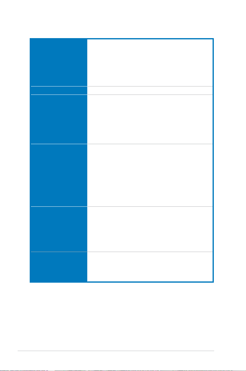
MAXIMUS V FORMULA Series specications summary
CPU LGA1155 socket for Intel® 3rd/2nd Generation Core™ i7 Core™ i5 /
Core™ i3 / Pentium® / Celeron® Processors
Supports 22/32nm CPU
Supports Intel® Turbo Boost Technology 2.0
* The Intel® Turbo Boost Technology 2.0 support depends on the CPU
types.
** Refer to www.asus.com for Intel CPU support list
Chipset Intel® Z77 Express Chipset
Memory 4 x DIMM, max. 32GB, DDR3 2800 (O.C.)* / 2600 (O.C.)* / 2400
(O.C.)* / 2200(O.C.) / 2133(O.C.) / 1866(O.C.) / 1600 / 1333 /
1066 MHz, non-ECC, un-buffered memory
Dual channel memory architecture
Supports Intel® Extreme Memory Prole (XMP)
* Hyper DIMM support is subject to the physical characteristics of
individual CPUs. Please refer to Memory QVL (Qualied Vendors List)
for details.
Expansion slots 3 x PCI Express 3.0*/2.0 x16 slots [red] (support x16, or dual at
x8/x8 mode, 3-way CFX at x8/x4/x4** native from CPU)
1 x PCI Express 2.0 x4 slot [black]
3 x PCI Express 2.0 slots
1 x mini-PCI Express 2.0 x1 slot*** on mPCIe Combo™ expansion
card
* Intel® 3rd generation Core™ processors support PCIe 3.0.
** Intel® 3rd generation Core™ processors supports x8/x4/x4 mode.
*** The mini-PCIe slot is pre-installed with a Wi-Fi/Bluetooth module.
VGA Integrated Graphics Processor - Intel® HD Graphics support
Multi-VGA output support: DisplayPort/HDMI port
Supports DisplayPort 1.1a with max. resolution of 2560 x 1600
@60Hz
Supports HDMI with max. resolution of 1920 x 1200 @60Hz
Supports Intel® InTru™ 3D/Quick Sync Video/Clear Video HD
Technology/Insider™
Multi-GPU support Supports NVIDIA® SLI™/AMD CrossFireX™ Technology
Supports AMD® 3-WAY CrossFireX™ Technology
Supports Lucidlogix Virtu MVP Technology*
*LucidLogix Virtu MVP supports Windows® 7 operating system.
(continued on the next page)
x
Page 11

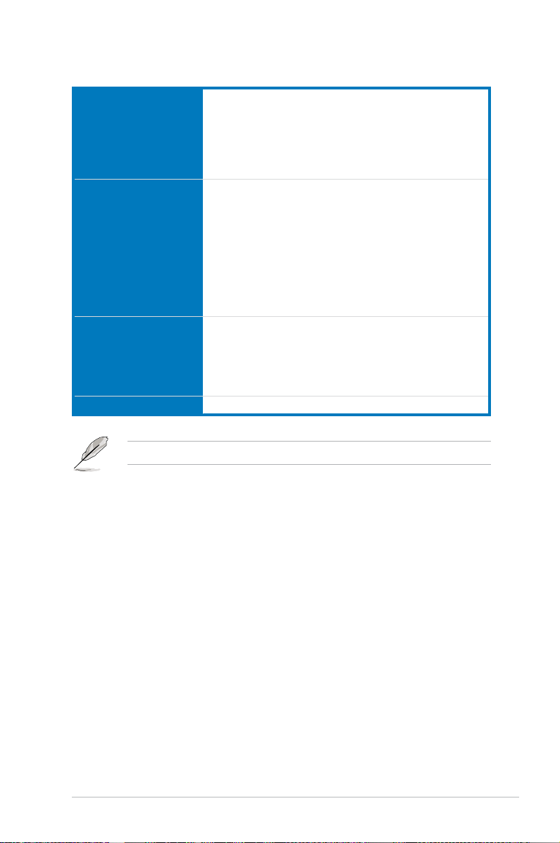
MAXIMUS V FORMULA Series specications summary
Storage
Intel® Z77 Express Chipset with RAID 0, 1, 5, 10 support
- 2 x SATA 6.0 Gb/s ports (red)
- 2 x SATA 3.0 Gb/s ports (black)
- 1 x eSATA 3.0 Gb/s ports
- 1 x mSATA 3.0 Gb/s slot on mPCIe Combo™ expansion card
- Supports Intel
Technology and Intel® Smart Connect Technology*
®
Smart Response Technology, Intel® Rapid Start
ASMedia® SATA 6Gb/s controller*
- 4 x SATA 6.0 Gb/s ports [red]**
* Supports Intel® Core™ processors on Windows® 7 operating system.
** These SATA ports are for data hard drives only. ATAPI devices are not
supported.
LAN 1 x Intel® Gigabit LAN Controller
Wireless Data Network Wi-Fi 802.11 a/b/g/n supports dual frequency band 2.4/5 GHz on
Bluetooth Bluetooth v4.0/3.0+HS
ROG SupremeFX HD
Audio
mPCIe Combo™ expansion card
* The module is pre-installed on the mPCIe Combo™
SupremeFX IV, built-in 7.1 Channel High Denition
Audo CODEC
High delity headphone amplier
Texas Instruments (120dB SNR, -117dB THD+N at VCC+-12V,
RL=600 Ω, f=1KHz)
SupremeFX Shielding™ Technology
ELNA Premium Audio Capacitors
1500 uF Audio Power Capacitor
Output Signal-to-Noise Ratio (A-Weighted): 110dB
Output THD+N at 1KHz: 95dB
Supports jack-detection, multi-streaming, front panel jack-retasking
Blu-ray audio layer content protection
Optical S/PDIF input and output ports at back panel
Audio Features:
DTS Ultra PC II
DTS Connect
USB
Intel® Z77 Express Chipset
- 4 x USB 3.0 ports (2 ports at mid-board [red]*, 2 ports at back
panel [blue])
- 8 x USB 2.0 ports (4 ports at mid-board, 1 port reserved for
ROG Connect [white], 3 ports at back panel)
ASMedia® USB 3.0 controller
- 2 x USB 3.0 ports at back panel (blue)
* UASP standard on the Intel® native USB 3.0 only supports Windows® 8.
(continued on the next page)
xi
Page 12

MAXIMUS V FORMULA Series specications summary
ROG Exclusive Features mPCIe Combo™ (mPCIe/mSATA combo card)
ROG Connect
- RC Diagram
- RC Remote
- RC Poster
- GPU TweakIt
ROG Extreme Engine Digi+ II
- 8-phase CPU power
- 4-phase iGPU power
- 2-phase DRAM power
UEFI BIOS features
- ROG BIOS Print
- GPU.DIMM Post
ROG Extreme OC Kit
- LN2 Mode
- Slow Mode
- EZ Plug
CPU Level Up
GameFirst II
Probelt
iROG
Extreme Tweaker
USB BIOS Flashback
Loadline Calibration
ROG O.C. Prole
Special Features ASUS EPU Engine
ASUS Wi-Fi GO!
ASUS Exclusive Features
- AI Suite II
- TurboV EVO
- USB 3.0 Boost
- Fan Xpert2
- AI Charger+
- USB Charger+
- Disk Unlocker
ASUS EZ DIY
- ASUS CrashFree BIOS 3
- ASUS EZ Flash 2
- ASUS C.P.R. (CPU Parameter Recall)
ASUS Q-Design
- ASUS Q-Code
- ASUS Q-Shield
- ASUS Q-Connector
- ASUS Q-LED (CPU, DRAM, VGA, Boot Device LED)
- ASUS Q-Slot
- ASUS Q-DIMM
(continued on the next page)
xii
Page 13

MAXIMUS V FORMULA Series specications summary
Back I/O Ports 1 x Clear CMOS button
1 x ROG Connect On/Off button
4 x USB 2.0 (1 port for ROG Connect)
1 x eSATA 3.0 Gb/s connector
4 x USB 3.0 ports [blue]
1 x Optical S/PDIF IN
1 x Optical S/PDIF OUT
1 x HDMI port
1 x DisplayPort
1 x LAN (RJ45) port
5 x audio jacks
Internal Connectors 1 x USB 3.0 connector (supports additional 2 USB 3.0 ports)
2 x USB 2.0 connectors (support additional 4 USB 2.0 ports)
6 x SATA 6.0 Gb/s connectors
2 x SATA 3.0 Gb/s connectors
2 x CPU fan connectors
3 x Chassis fan connectors
3 x Optional fan connectors
3 x Thermal sensor connectors
1 x 24-pin EATX power connector
1 x 8-pin EATX 12V power connector
1 x 4-pin EATX 12V power connector
8 x Probelt measurement points
1 x EZ Plug connector
1 x LN2 Mode header
1 x Slow mode switch
1 s START (Power-on) button
1 x RESET button
1 x GO button
1 x S/PDIF OUT header
1 x Front panel audio connector (AAFP)
1 x System panel connector
1 x mPCIe Combo™ header
Manageability WfM2.0, DMI2.0, WOL by PME, PXE
(continued on the next page)
xiii
Page 14

MAXIMUS V FORMULA Series specications summary
BIOS Features 64Mb UEFI AMI BIOS, PnP, DMI2.0, WfM2.0, SM BIOS 2.5,
Software Drivers
Form Factor extended ATX Form Factor, 12” x 10.1” (30.5cm x 25.7cm)
Specications are subject to change without notice.
ACPI2.0a Multi-language BIOS
Kaspersky® Anti-Virus
DAEMON Tools Pro Standard
GameFirst II
ROG CPU-Z
Mem TweakIt
ASUS AI Suite II
ASUS WebStorage
ASUS Utilities
xiv
Page 15
ROG ThunderFX specications summary
Audio Performance Output Signal-to-Noise Ratio (A-Weighted): 114dB
Digital-to-analog converter: 120dB SNR, 107dB THD+N (Max.
192kHz/24-bit)
C-Media 6631 audio processor (Max. 192kHz/ 24-bit)
Built-in high delity headphone amplier
Up to 300-ohms headphone ratio support
Special Features Multi-platform Support: PC, Xbox 360, PS3
Independent master / voice / game volume control (PS3. Xbox 360)
Built-in ENC (Environmental Noise Cancellation) Technology
GameEQ: 3 preset EQ proles with graphical audio effect tuning
hints
Xear™ Surround headphone
Xear™ SingFX
FlexBass™, Smart Volume Normalize™
DS3D GX 1.0, OpenAL
I/O Ports 2 x RCA audio input
1 x USB 2.0 connector
1 x 3.5mm headphone jack
1 x 3.5mm microphone jack
1 x 2.5mm microphone jack for Xbox 360 voice input
Dimensions 191mm x 137.5mm x 37mm (L x W x H)
Specications are subject to change without notice.
xv
Page 16

Package contents
Check your motherboard package for the following items.
Motherboard ROG MAXIMUS V FORMULA
USB external sound card ROG ThunderFX*
Cables 1 x ROG Connect cable
2 x 2-in-1 SATA 6.0 Gb/s signal cables
1 x 2-in-1 SATA 3.0 Gb/s signal cables
1 x 2-in-1 RF cables
1 x SLI bridge
1 x Xbox 360 voice input cable (2.5mm)**
1 x Dual-head USB cable**
1 x ThunderFX Xbox 360 AV +3.5mm-to-RCA cable**
Accessories I/O Shield
1 x mPCIe Combo card with dual band Wi-Fi / Bluetooth
module
2 x dual band Wi-Fi Ring Moving Antenna
1 x 12-in-1 ROG cable label
1 x 2-in-1 ASUS Q-Connector kit
1 x Diablo III mousepad**
1 x ROG logo sticker**
Application DVD
Documentation
ROG motherboard support DVD
User guide
xvi
• If any of the above items is damaged or missing, contact your retailer.
• *ThunderFX is only available in selected models.
• ** These items are bundled with ThunderFX.
Page 17
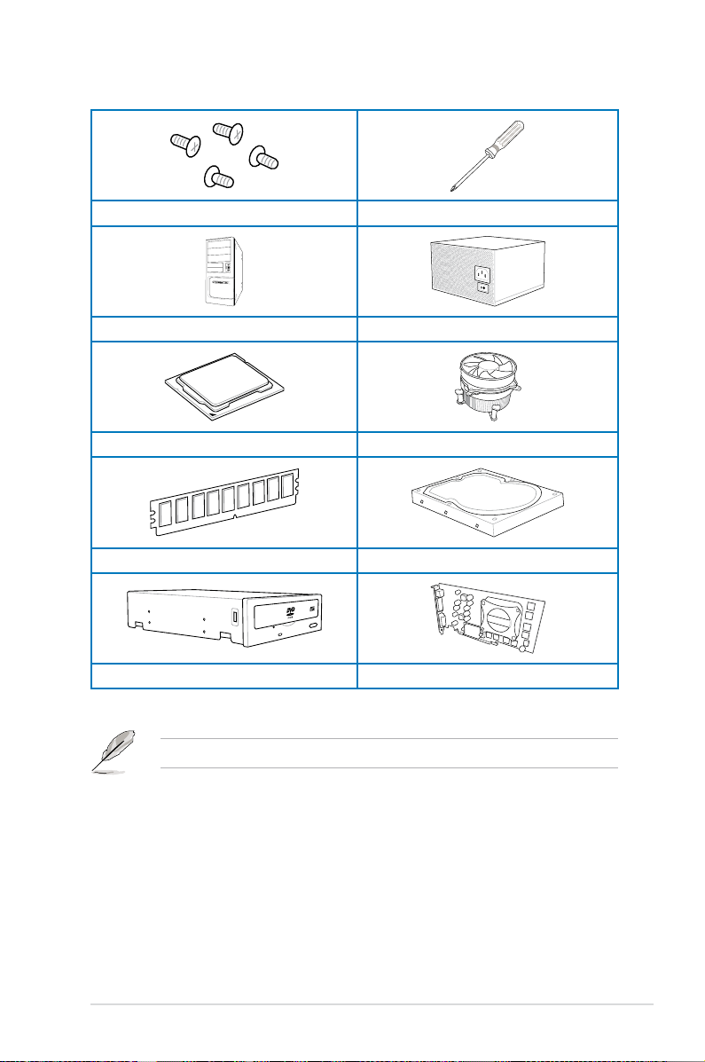
Installation tools and components
1 bag of screws Philips (cross) screwdriver
PC chassis Power supply unit
Intel LGA 1155 CPU Intel LGA 1155 compatible CPU Fan
DIMM SATA hard disk drive
SATA optical disc drive (optional) Graphics card (optional)
The tools and components in the table above are not included in the motherboard package.
xvii
Page 18

xviii
Page 19

Product introduction
1
1.1 Special features
1.1.1 Product highlights
Republic of Gamers
The Republic of Gamers offers you the best of the best. We offer the best hardware
engineering, the fastest performance, the most innovative ideas, and we welcome the best
gamers to join in. In the Republic of Gamers, mercy rules are only for the weak, and bragging
rights means everything. We believe in making statements and we excel in competitions.
If your character matches our trait, then join the elite Republic of Gamers and make your
presence felt.
LGA1155 socket for Intel® 2nd/3rd Generation Core™ i7 / Core™ i5 / Core™
i3, Pentium®, and Celeron® Processors
This motherboard supports Intel 2nd/3rd generation Core™ i7/i5/i3, Pentium, and Celeron
processors in the LGA1155 package. It provides great graphics and system performance with
its GPU, dual-channel DDR3 memory slots, and PCI Express 2.0/3.0 expansion slots.
Intel® Z77 Express Chipset
Intel® Z77 Express Chipset is a single-chipset that supports the 1155 socket Intel® 2nd/3rd
generation Core™ i7/i5/ i3, Pentium®, and Celeron® processors. It utilizes the serial point-topoint links, which increases bandwidth and enhances the system’s performance. It natively
supports four USB 3.0 ports for up to ten times faster transfer rate than USB 2.0, and enables
the iGPU function for Intel® integrated graphics performance.
PCI Express® 3.0
PCI Express® 3.0 (PCIe 3.0) is the PCI Express bus standard that provides twice the
performance and speed of PCIe 2.0. It provides an optimal graphics performance,
unprecedented data speed, and seamless transition with its complete backward compatibility
to PCIe 1.0/2.0 devices.
* Intel® 3rd generation Core™ processors support PCIe 3.0.
SLI/CrossFire On-Demand
This motherboard features a unique PCIe 3.0 bridge chip to support multi-GPU SL/
CrossFireX graphics cards for an unrivaled gaming performance. With the Intel Z77 platform
to optimize the PCIe allocation of multiple GPUs, it supports up to 2-WAY GPU SLI or 3-WAY
GPU CrossFireX conguration.
ASUS MAXIMUS V FORMULA Series
Chapter 1
1-1
Page 20

LucidLogix® Virtu™ MVP
LucidLogix® Virtu™ MVP, with HyperFormance™ Technology, is designed for Intel® processor
graphics chip on Windows® 7 and perfectly combines the performance of a discrete graphics
card with fast computing iGPU (Integrated Graphics Processing Unit). The newly-designed
Virtual VSync eliminates tearing artifacts allowing you to enjoy a smoother gaming
experience.
LucidLogix® Virtu™ MVP can also dynamically assign tasks to the best available graphics
resource based on power, performance, and system load. With Intel® Quick Sync Video 2.0
technology, it provides 3x faster video conversion of NVIDIA and AMD graphics cards while
retaining the graphics cards’ high-end 3D rendering and gaming performance. When the
discrete graphics cards are not in use, it drastically reduces the power usage, making the
system more environmentally friendly.
* LucidLogix® Virtu™ MVP supports Windows® 7 operating system.
®
** Intel
Quick Sync Video feature is supported by 2nd/3rd generation Intel® Core™ processor family.
1.1.2 ROG unique gaming features
SupremeFX IV
The SupremeFX IV™ onboard audio solution is a set of audio capacitors that produce a
crisp, warm sound. With the bundled 300-ohm built-in headphone amplier, SupremeFX IV™
provides you with better gaming audio experience. Combined with the existing SupremeFX
innovation such as the Red Line physical PCB separation, and EMI shield, SupremeFX sets
an unrivaled audio standard for PC gamers.
GameFirst II
ASUS GameFirst II, with cFOS Trafc Shaping technology, provides a powerful and user-
friendly network control to easily frag your gaming system. Featuring the EZ Mode for
beginners’ setup and Advanced Mode for professionals’ tweaking, your frags comes rst.
ThunderFX
ThunderFX is an audio device that produces a premium gaming audio and easily connects
to your favorite PC headphones on any PC, laptop or console. Its Environmental Noise
Cancellation (ENC) technology reduces the gaming background noise and GamEQ provides
a 3-preset gaming audio genre and four audio effect hints for a quick and easy tuning. Its
300-ohm amplied headphone and premium Nichicon FG Series capacitors provide a pure
and powerful audio. ThunderFX is a supreme sound accessory t for your console and
network gaming entertainment.
1.1.3 ROG Intelligent Performance & Overclocking features
mPCIe Combo + Dual band Wi-Fi / Bluetooth 4.0
Chapter 1
The mPCIe Combo is a two-sided mini-card that allows you to install an extra mSATA SSD
and a Wi-Fi module into the motherboard. This device comes with one mSATA port that
supports Intel® Smart Response Technology hybrid storage acceleration, and a dual-band
2.4/5 GHz Wi-Fi 802.11 a/b/g/n and Bluetooth v4.0 functions.
1-2
Chapter 1: Product introduction
Page 21

Fusion Thermo
ROG Fusion Thermo is a VRM cooler made from a combination of 100% copper water
cooling channel with electro-plated nickel barbs, and anodized aluminum nned air-cooler.
With both water-cooling and air-cooling features, Fusion Thermo delivers the ultimate add-on
to achieve the best O.C. advantage.
ROG Connect
ROG Connect allows you to monitor the status of your desktop PC and tweak its parameters
in real-time via a notebook. ROG Connect links your main system to a notebook through a
USB cable, allowing you to view real-time POST code and hardware status readouts on your
notebook, as well as make on-the-y parameter adjustments at a purely hardware level.
Extreme Engine Digi+ II
The Extreme Engine Digi+ II is equipped with the nest Japan-made 10K Black Metallic
capacitors, and its digital VRM design allows you to achieve ultimate performance with
adjustable CPU and memory power management frequencies.
USB BIOS FlashBack
USB BIOS Flashback offers a hassle-free updating solution for your ultimate convenience.
Simply install a USB storage device containing the BIOS le, press the BIOS Flashback
button for three seconds, and the UEFI BIOS is automatically updated even without entering
the existing the BIOS or operating system. It also allows you to regularly check for UEFI
BIOS updates, and download the latest BIOS automatically.
iROG
The iROG is a special IC that fully maximizes ROG’s unique functions, providing you with full
control of your motherboard at any stage. It greatly increases your overclocking enjoyment,
and offers you with advanced system control and management features purely at a hardware
level.
CPU Level Up
With ROG’s CPU Level Up, overclocking has never been so easy, or cost-free. Simply select
the processor that you want to overclock to, and the motherboard will do the rest.
GPU.DIMM Post
GPU.DIMM Post enables you to catch potential problems even before you enter the OS,
saving you valuable time in detecting component failure under extreme conditions. With GPU.
DIMM Post, quickly and easily check your graphic cards, memory modules’ statuses in the
BIOS, and overclocking settings.
ASUS MAXIMUS V FORMULA Series
Chapter 1
1-3
Page 22

BIOS Print
ROG offers a whole new UEFI BIOS feature to handle the demands of an overclocking
experience. The motherboard features ROG BIOS Print that allows you to easily share your
BIOS settings to others with the press of a button.
ProbeIt
This motherboard consists of seven Probelt measurement points that helps you detect your
system’s current voltage. With the use of a multimeter device, these points can help measure
your system’s ground, platform controller hub, CPU phase locked loop, input.output, memory,
iGPU, and GPU voltages.
Extreme Tweaker
Extreme Tweaker is the one stop shop to ne-tune your system to optimal performance.
With Extreme Tweaker, you can adjust the system settings such as frequency, over-voltage,
memory timing, and more.
Loadline Calibration
Maintaining ample voltage support for the CPU is critical during overclocking. The
Loadline Calibration ensures stable and optimal CPU voltage under heavy loading. It helps
overclockers enjoy the motherboard's ultimate OC capabilities and benchmark scores.
1.1.4 ASUS special features
Intel Gigabit LAN
The LAN solution from Intel has been long known to have a better throughput, lower CPU
utilization as well as better stability. With the Intel Gigabit LAN solutions onboard, the
ultimate network experience can therefore be delivered to its users like never before.
USB 3.0 Boost
ASUS USB 3.0 Boost technology supports UASP (USB Attached SCSI Protocol), the latest
USB 3.0 standard. With USB 3.0 Boost technology, a USB device’s transmission speed is
signicantly increased up to 170%, adding to an already impressive fast USB 3.0 transfer
speed. It automatically accelerates data speeds for compatible USB 3.0 peripherals without
the need for any user interaction.
1.1.5 ROG-rich bundled software
Kaspersky® Anti-Virus
Kaspersky® Anti-Virus Personal offers premium antivirus protection for individual users and
home ofces. It is based on advanced antivirus technologies. The product incorporates the
Kaspersky® Anti-Virus engine, which is renowned for malicious program detection rates that
Chapter 1
are among the industry’s highest.
1-4
Chapter 1: Product introduction
Page 23

DAEMON Tools Pro Standard
DAEMON Tools Pro offers essential functionality to backup CD, DVD and Blu-ray discs. It
converts optical media into virtual discs and emulates devices to work with the virtual copies.
DAEMON Tools Pro organizes data, music, video, and photo collections on a PC, notebook,
or netbook.
ROG CPU-Z
ROG CPU-Z, authorized by Intel’s CPU Identication (CPUID), is a customized ROG utility
that allows you to gather information about your system’s main components. It gives you
the current information and status of your CPU, motherboard, memory, and other main
components. Get that ROG look of reporting your system’s current information with ROG
CPU-Z.
ASUS MAXIMUS V FORMULA Series
Chapter 1
1-5
Page 24

1.2 Motherboard overview
1.2.1 Before you proceed
Take note of the following precautions before you install motherboard components or change
any motherboard settings.
• Unplug the power cord from the wall socket before touching any component.
• Before handling components, use a grounded wrist strap or touch a safely grounded
object or a metal object, such as the power supply case, to avoid damaging them due
to static electricity.
• Hold components by the edges to avoid touching the ICs on them.
• Whenever you uninstall any component, place it on a grounded antistatic pad or in the
bag that came with the component.
• Before you install or remove any component, ensure that the ATX power supply is
switched off or the power cord is detached from the power supply. Failure to do so
may cause severe damage to the motherboard, peripherals, or components.
Chapter 1
1-6
Chapter 1: Product introduction
Page 25
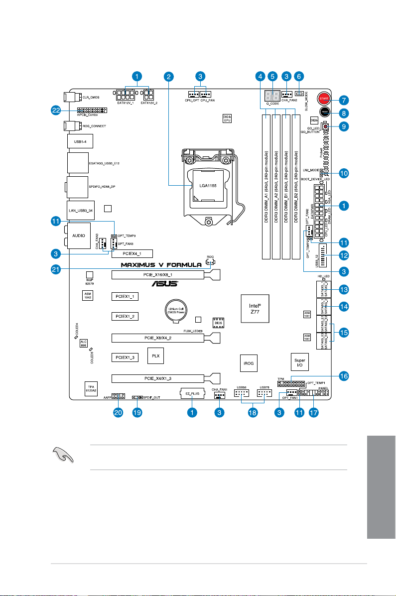
1.2.2 Motherboard layout
Refer to 1.2.9 Internal connectors and 2.3.1 Rear I/O connection for more information
about rear panel connectors and internal connectors.
ASUS MAXIMUS V FORMULA Series
Chapter 1
1-7
Page 26

Layout contents
Connectors/Jumpers/Buttons and switches/Slots Page
1. Power connectors (24-pin EATXPWR, 8-pin EATX12V, 4-pin EATX12V;
4-pin EZ_PLUG)
LGA1155 CPU Socket 1-9
2.
CPU, chassis, and optional fan connectors (4-pin CPU_FAN, 4-pin
3.
CPU_OPT, 4-pin OPT_FAN1-3, 4-pin CHA_FAN1-3)
4. DDR3 DIMM slots
5. Q_Code LEDs
6. Slow Mode switch
7. START (Power-on) button
8. RESET button
9. GO button
10. LN2 Mode header
11. Thermal sensor cable connectors (2-pin OPT_TEMP1/2/3)
12. USB 3.0 connectors (20-1 pin USB3_12)
®
13. Intel
14. Intel
15. Asmedia
[red])
16. TPM connector
17. System panel connector (20-8 pin PANEL)
18. USB 2.0 connectors (10-1 pin USB56; USB78)
19. Digital audio connector (4-1 pin SPDIF_OUT)
20. Front panel audio connector (10-1 pin AAFP)
21. ROG Logo LED connector (3-pin)
22. mPCIe combo connector (26-1 pin mPCIe)
Z77 Serial ATA 3.0 Gb/s connectors (7-pin SATA3G_1/2 [black]) 1-37
®
Z77 Serial ATA 6.0 Gb/s connectors (7-pin SATA6G_1/2 [red]) 1-36
®
Z77 Serial ATA 6.0 Gb/s connectors (7-pin SATA6G_E12/E34
1-43
1-41
1-10
1-29
1-25
1-24
1-24
1-25
1-26
1-45
1-39
1-38
1-45
1-44
1-40
1-39
1-42
1-46
2-12
Chapter 1
1-8
Chapter 1: Product introduction
Page 27
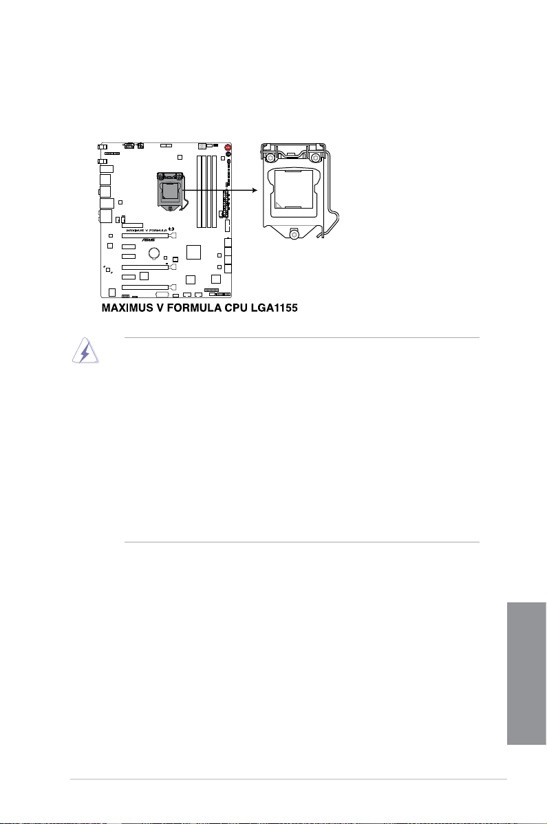
1.2.3 Central Processing Unit (CPU)
The motherboard comes with a surface mount LGA1155 socket designed for the Intel®
3rd/2nd Generation Core™ i7 / Core™ i5 / Core™ i3, Pentium™, and Celeron™ processors.
• Ensure that all power cables are unplugged before installing the CPU.
• The LGA1156 CPU is incompatible with the LGA1155 socket. DO NOT install a
LGA1156 CPU on the LGA1155 socket.
• Upon purchase of the motherboard, ensure that the PnP cap is on the socket and
the socket contacts are not bent. Contact your retailer immediately if the PnP cap
is missing, or if you see any damage to the PnP cap/socket contacts/motherboard
components. ASUS will shoulder the cost of repair only if the damage is shipment/
transit-related.
• Keep the cap after installing the motherboard. ASUS will process Return Merchandise
Authorization (RMA) requests only if the motherboard comes with the cap on the
LGA1155 socket.
• The product warranty does not cover damage to the socket contacts resulting from
incorrect CPU installation/removal, or misplacement/loss/incorrect removal of the PnP
cap.
ASUS MAXIMUS V FORMULA Series
Chapter 1
1-9
Page 28
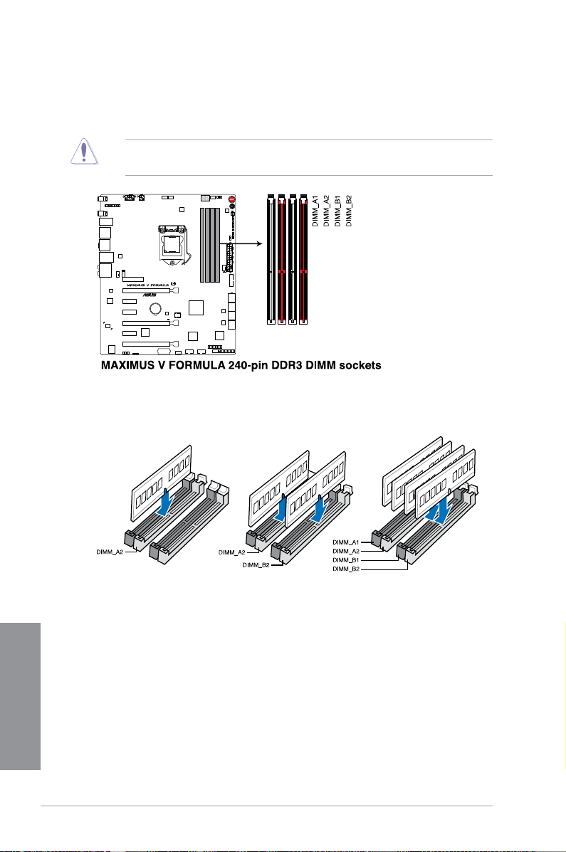
1.2.4 System memory
The motherboard comes with four Double Data Rate 3 (DDR3) Dual Inline Memory Modules
(DIMM) slots.
A DDR3 module is notched differently from a DDR or DDR2 module. DO NOT install a DDR
or DDR2 memory module to the DDR3 slot.
Recommended memory congurations
Chapter 1
1-10
Chapter 1: Product introduction
Page 29

Memory congurations
You may install 1GB, 2GB, 4GB and 8GB unbuffered and non-ECC DDR3 DIMMs into the
DIMM sockets.
• Memory module with memory frequency higher than 2133 MHz and its corresponding
timing or the loaded XMP prole is not the JEDEC memory standard. The stability and
compatibility of these memory modules depend on the CPU’s capabilities and other
installed devices.
• You may install varying memory sizes in Channel A and Channel B. The system maps
the total size of the lower-sized channel for the dual-channel conguration. Any excess
memory from the higher-sized channel is then mapped for single-channel operation.
• Due to Intel
DDR3 2000/1800 MHz memory modules will run at the default frequency rates of
DDR3 2133/1866/1600 MHz.
• According to Intel CPU spec, DIMM voltage below 1.65V is recommended to protect
the CPU.
• Always install DIMMs with the same CAS latency. For optimal compatibility, we
recommend that you install memory modules of the same version or date code (D/C)
from the same vendor. Check with the retailer to get the correct memory modules.
• Due to the memory address limitation on 32-bit Windows OS, when you install 4GB
or more memory on the motherboard, the actual usable memory for the OS can be
about 3GB or less. For effective use of memory, we recommend that you do any of the
following:
a) Use a maximum of 3GB system memory if you are using a 32-bit Windows OS.
b) Install a 64-bit Windows OS when you want to install 4GB or more on the
c) For more details, refer to the Microsoft
• This motherboard does not support DIMMs made up of 512Mb (64MB) chips or less
(Memory chip capacity counts in Megabit, 8 Megabit/Mb = 1 Megabyte/MB).
®
2nd generation processors' behavior, DDR3 2200 (and higher), and
motherboard.
®
com/kb/929605/en-us.
support site at http://support.microsoft.
• The default memory operation frequency is dependent on its Serial Presence Detect
(SPD), which is the standard way of accessing information from a memory module.
Under the default state, some memory modules for overclocking may operate at a
lower frequency than the vendor-marked value. To operate at the vendor-marked or at
a higher frequency, refer to section 3.3 Extreme Tweaker menu for manual memory
frequency adjustment.
• For system stability, use a more efcient memory cooling system to support a full
memory load (4 DIMMs) or overclocking condition.
ASUS MAXIMUS V FORMULA Series
Chapter 1
1-11
Page 30
MAXIMUS V FORMULA Series Motherboard Qualied Vendors Lists (QVL)
DDR3 2400 MHz capability
Vendors Part No. Size SS/DSChip
CORSAIR CMGTX8(XMP) 8GB (4x2GB) SS - - 10-12-10-30 1.65 • •
CORSAIR CMGTX3(XMP) 2GB DS - - 9-11-9-27 1.65 • •
G.SKILL F3-19200CL11Q-
16GBZHD (XMP)
G.SKILL F3-19200CL11Q-
16GBZHD (XMP)
G.SKILL F3-19200CL9Q-16GBZMD
(XMP)
G.SKILL F3-19200CL10Q-
32GBZHD (XMP)
G.SKILL F3-19200CL9D-4GBPIS
(XMP)
GEIL GOC316GB2400C10QC
(XMP)
GEIL GOC316GB2400C11QC
(XMP)
Kingston KHX2400C11D3K4/8GX
(XMP)
Transcend TX2400KLU-4GK (381850)
(XMP)
Transcend TX2400KLU-4GK(374243)
(XMP)
Patriot PVV34G2400C9K(XMP) 4GB (2x2GB) DS - - 9-11-9-27 1.66 •
16GB (4x4GB) DS - - 11-11-11-31 1.65 • • •
16GB (4x4GB) DS - - 11-11-11-31 1.65 • •
16GB (4x4GB) DS - - 9-11-11-31 1.65 • • •
32GB (4x8GB) DS - - 10-12-12-31 1.65 • • •
4G (2x2GB) DS - - 9-11-9-28 1.65 • •
16GB (4x4GB) DS - - 10-11-11-30 1.65 • • •
16GB (4x4GB) DS - - 11-11-11-30 1.65 • • •
8GB (4x2GB) SS - - 11-13-11-30 1.65 • • •
2GB DS - - - 1.65 • • •
2GB DS - - - 1.65 • • •
Brand
Chip
Timing Voltage DIMM socket
NO.
support (Optional)
1 2 4
DDR3 2200 MHz capability
Vendors Part No. Size SS/DSChip
G.SKILL F3-17600CL7D-4GBFLS(XMP) 4G (2x2G) DS - - 7-10-
GEIL GET34GB2200C9DC(XMP) 4GB (2x2GB) DS - - 9-10-9-28 1.65 • • •
GEIL GET38GB2200C9ADC(XMP) 8GB (2x4GB) DS - - 9-11-9-28 1.65 • • •
KINGMAX FLKE85F-B8KJAA-FEIS(XMP) 4GB (2x2GB) DS Kingmax N/A - - •
Brand
Chip
Timing Voltage DIMM socket
NO.
10-28
1.65 • •
support (Optional)
1 2 4
Chapter 1
1-12
Chapter 1: Product introduction
Page 31

DDR3 2133 MHz capability
Vendors Part No. Size SS/DSChip
A-DATA AX3U2133C2G9B(XMP) 2GB SS - - 9-11-9-27 1.55~1.75 •
A-DATA AX3U2133GC2G9B(XMP) 2GB SS - - 9-9-9-24 1.55-1.75 • •
A-DATA AX3U2133GC4G9B(XMP) 16GB (4x4GB) DS - - 9-11-9-27 1.65 • • •
Apacer 78.BAGE4.AFD0C(XMP) 8GB (2x4GB) DS - - 9-9-9-24 - • • •
CORSAIR CMT4GX3M2A2133C9(XMP) 4GB (2x2GB) DS - - 9-10-9-24 1.65 • •
CORSAIR CMT4GX3M2B2133C9
CORSAIR CMT4GX3M2B2133C9(XMP) 4GB (2x2GB) DS - - 9-10-9-27 1.5 • • •
G.SKILL F3-17000CL9Q-
G.SKILL F3-17000CL9Q-16GBZH(XMP) 16GB (4x4GB) DS - - 9-11-10-28 1.65 • • •
G.SKILL F3-17066CL9Q-
G.SKILL F3-17000CL11Q2-
G.SKILL F3-17066CL9D-8GBPID(XMP) 8GB (2x4GB) DS - - 9-9-9-24 1.65 • •
KINGSTON KHX2133C11D3K4/16GX(XMP) 16GB (4x4GB) DS - - 11-12-11-30 1.65 • • •
OCZ OCZ3XTEP2133C9LV4GK 2GB DS - - 7-7-7-20 1.65 • •
Patriot PVV34G2133C9K(XMP) 4GB (2x2GB) DS - - 9-11-9-27 1.66 • •
(Ver7.1)(XMP)
16GBXLD(XMP)
16GBTDD(XMP)
64GBZLD(XMP)
4GB (2x2GB) DS - - 9-9-9-24 1.5 • • •
16GB (4x4GB) DS - - 9-11-9-28 1.65 • • •
16GB (4x4GB) DS - - 9-9-9-24 1.65 • •
64GB (8x8GB) DS - - 11-11-11-30 1.5 • • •
Brand
Chip
Timing Voltage DIMM socket
NO.
support
(Optional)
1 2 4
ASUS MAXIMUS V FORMULA Series
Chapter 1
1-13
Page 32

DDR3 2000 MHz capability
Vendors Part No. Size SS/DSChip
A-DATA AX3U2000GB2G9B
(XMP)
A-DATA AX3U2000GC4G9B
(XMP)
Apacer 78.AAGD5.9KD(XMP) 6GB(3x2GB) DS - - 9-9-9-27 - • • •
CORSAIR CMZ4GX3M2A2000C10
(Ver 5.12) (XMP)
CORSAIR CMT6GX3M3A2000C8
(XMP)
G.SKILL F3-16000CL9D-4GBRH
(XMP)
G.SKILL F3-16000CL9D-4GBTD
(XMP)
GEIL GUP34GB2000C9DC
(XMP)
Transcend TX2000KLN-8GK(388375)
(XMP)
AEXEA AXA3ES2G2000LG28V
(XMP)
AEXEA AXA3ES4GK2000LG28V
(XMP)
Asint SLA302G08-ML2HB
(XMP)
Gingle FA3URSS673A801A 2GB DS - - 9-9-9-24 - • •
Patriot PX7312G2000ELK(XMP) 12GB
Patriot PV736G2000ELK(XMP) 6GB (3x2GB) DS - - 7-7-7-20 1.65 • •
Silicon
SP002GBLYU200S02
Power
(XMP)
Team TXD32048M2000C9
(XMP)
Team TXD32048M2000C9-L
(XMP)
Team TXD32048M2000C9-L
(XMP)
2GB DS - - 9-11-9-27 1.55~1.75 • • •
4GB DS - - 9-11-9-27 1.55~1.75 • • •
4GB (2x2GB) SS - - 10-10-
6GB (3x2GB) DS - - 8-9-8-24 1.65 • • •
4GB(2x2GB) DS - - 9-9-9-24 1.65 • •
4GB(2x2GB) DS - - 9-9-9-24 1.65 • •
4GB (2x2GB) DS - - 9-9-9-28 1.65 • • •
4GB DS - - - 1.6 • •
2GB DS - - - 1.65 • • •
4GB (2x2GB) DS - - - 1.65 • •
4GB DS Hynix H5TQ2G83
(3x4GB)
2GB DS - - - - • • •
2GB DS Team T3D1288RT-209-9-9-24 1.5 • • •
2GB DS Team T3D1288LT-209-9-9-24 1.5 • • •
2GB DS Team T3D1288RT-209-9-9-24 1.6 • • •
DS - - 9-11-9-27 1.65 • • •
Chip NO. Timing Voltage DIMM socket
Brand
1.5 • •
BFRH9C
10-27
9-9-9-27 - • • •
support
(Optional)
1 2 4
Chapter 1
1-14
Chapter 1: Product introduction
Page 33

DDR3 1866 MHz capability
Vendors Part No. Size SS/DSChip
A-DATA AX3U1866GC2G9B(XMP) 2GB SS - - 9-11-9-27 1.55~
A-DATA AX3U1866GC4G9B(XMP) 4GB DS - - 9-11-9-27 1.55~
CORSAIR CMT32GX3M4X1866C9
(Ver3.23)(XMP)
CORSAIR CMZ32GX3M4X1866C10
(Ver3.23)(XMP)
CORSAIR CMZ8GX3M2A1866C9
(XMP)
Crucial BLE4G3D1869DE1XT0.
16FMD(XMP)
G.SKILL F3-14900CL9Q-16GBXL
(XMP)
G.SKILL F3-14900CL9Q-16GBZL
(XMP)
G.SKILL F3-14900CL10Q2-64GB
ZLD(XMP)
G.SKILL F3-14900CL9D-8GBSR
(XMP)
G.SKILL F3-14900CL9Q-8GBFLD
(XMP)
Patriot PXD34G1866ELK(XMP) 4GB (2x2GB) SS - - 9-9-9-24 1.65 • • •
Patriot PXD38G1866ELK(XMP) 8GB (2x4GB) DS - - 9-11-9-27 1.65 • • •
Patriot PXD38G1866ELK(XMP) 8GB (2x4GB) DS - - 9-9-9-24 1.65 • • •
Team TXD34096M1866HC9K
-L(XMP)
32GB
(4x8GB)
32GB
(4x8GB)
8GB (2x4GB) DS - - 9-10-9-27 1.5 • • •
4GB DS - - 9-9-9-27 1.5 • • •
16GB
(4x4GB)
16GB
(4x4GB)
64GB
(8x8GB)
8GB (2x4GB) DS - - 9-10-9-28 1.5 • • •
8GB (2x4GB) DS - - 9-9-9-24 1.6 • • •
4GB DS Hynix H5TC2G
DS - - 9-10-9-27 1.5 • •
DS - - 10-11-
DS - - 9-10-9-28 1.5 • • •
DS - - 9-10-9-28 1.5 • • •
DS - - 10-11-
Chip NO. Timing Voltage DIMM socket
Brand
1.75
1.75
10-27
10-30
9-11-9-27 1.65 • • •
3BFRH9A
1.5 • • •
1.5 • • •
support (Optional)
1 2 4
• •
• • •
DDR3 1800 MHz capability
Vendors Part No. Size SS/DSChip
G.SKILL F3-14400CL9D-4G BRL(XMP) 4GB (2x2GB) DS - - 9-9-9-241.6 • • •
ASUS MAXIMUS V FORMULA Series
Brand
Chip
Timing Voltage DIMM socket
NO.
support
(Optional)
1 2 4
Chapter 1
1-15
Page 34

DDR3 1600 MHz capability
Vendors Part No. Size SS/DSChip
A-DATA AM2U16BC2P1 2GB SS A-DATA 3CCD-
A-DATA AM2U16BC4P2 4GB DS A-DATA 3CCD-
A-DATA AX3U1600GC4G9
A-DATA AX3U1600PC4G8
CORSAIR CMZ8GX3M4X1600C9
CORSAIR HX3X12G1600C9 (XMP) 12GB (6x2GB) DS - - 9-9-9-24 1.6 • • •
CORSAIR CML16GX3M4X1600C8
CORSAIR CMZ16GX3M4A1600C9
CORSAIR CMZ32GX3M4X1600C10
CORSAIR CMG4GX3M2A1600C6 4GB (2x2GB) DS - - 6-6-6-18 1.65 • • •
CORSAIR CMP6GX3M3A1600C8
CORSAIR CMP6GX3M3A1600C8
CORSAIR CMX6GX3M3C1600C7
CORSAIR CMZ8GX3M2A1600C8
CORSAIR CMZ8GX3M2A1600C9
Crucial BL12864BN1608.8FF
Crucial BLT4G3D1608DT1TX0.
G.SKILL F3-12800CL7Q-16GBXH
G.SKILL F3-12800CL9Q-16GBXL
G.Skill F3-12800CL9Q-16GBZL
G.SKILL F3-12800CL7D-8GBRH
Chapter 1
G.SKILL F3-12800CL9D-8GBRL
( XMP)
(XMP)
(Ver2.12)(XMP)
(Ver 2.12)(XMP)
(XMP)
(Ver2.2)(XMP)
(XMP)
(XMP)
(XMP)
(XMP)
(XMP)
(XMP)
16FM(XMP)
(XMP)
(XMP)
(XMP)
(XMP)
(XMP)
Chip
Brand
4GB DS - - - 1.55~1.75 • • •
4GB DS - - 8-8-8-24 1.55~1.75 • • •
8GB (4x2GB) SS - - 9-9-9-24 1.5 • • •
16GB (4x4GB) DS - - Heat-
16GB (4x4GB) DS - - 9-9-9-24 1.5 • • •
32GB (4x8GB) DS - - 10-10-
6GB (3x2GB) DS - - 8-8-8-24 1.65 • • •
6GB (3x2GB) DS - - 8-8-8-24 1.65 • • •
6GB (3x2GB) DS - - 7-8-7-20 1.65 • • •
8GB (2x4GB DS - - 8-8-8-24 1.5 • • •
8GB (2x4GB) DS - - 9-9-9-24 1.5 • • •
2GB(2x1GB) SS - - 8-8-8-24 1.65 • • •
4GB DS - - 8-8-8-24 1.5 • • •
16GB (4x4GB) DS - - 7-8-7-24 1.6 • • •
16GB (4x4GB) DS - - 9-9-9-24 1.5 • •
16GB (4x4GB) DS - - 9-9-9-24 1.5 • • •
8GB (2x4GB) DS - - 7-8-7-24 1.6 • • •
8GB (2x4GB) DS - - 9-9-9-24 1.5 • • •
Timing Voltage DIMM socket
NO.
- - • • •
1509A
- - • • •
1509A
1.5 •
Sink
Package
1.5 • • •
10-27
support (Optional)
1 2 4
(continued on the next page)
1-16
Chapter 1: Product introduction
Page 35

DDR3 1600 MHZ Capability
Vendors Part No. Size SS/DSChip
G.SKILL F3-12800CL9D-8GBSR
G.SKILL F3-12800CL8D-
GEIL GET316GB1600C9QC
GEIL GUP34GB1600C7DC
KINGMAX FLGE85F-C8KL9A
KINGMAX FLGF65F-
KINGSTON KHX1600C9D3K3/
KINGSTON KHX1600C9D3T1BK3/
KINGSTON KHX1600C9D3K3/
KINGSTON KHX1600C9D3K6/
Kingston KHX1600C9D3K8/
KINGSTON KHX1600C9D3K2/
KINGSTON KHX1600C9D3LK2/
KINGSTON KHX1600C9D3X2K2/
KINGSTON KHX1600C9D3K3/
KINGSTON KHX1600C9D3K3/
KINGSTON KHX1600C9D3T1K3/
KINGSTON KHX1600C9D3P1K2/8G8GB (2x4GB) DS - - 9 1.5 • • •
OCZ OCZ3BE1600C8LV4GK 4GB(2x2GB) DS - - 8-8-8 1.65 • •
Transcend TS256MLK64V6N 2GB SS Transcend K4B2G
Transcend TS512MLK64V6N 4GB DS Transcend K4B2G
Transcend JM1600KLN-8GK 8GB (2x4GB) DS Transcend TK483
Asint SLZ3128M8-
Asint SLA302G08-
2(XMP)
8GBECO (XMP)
(XMP)
(XMP)
(XMP)
C8KL9A(XMP)
12GX (XMP)
12GX (XMP)
12GX(XMP)
24GX(XMP)
32GX(XMP)
4GX(XMP)
4GX(XMP)
4GX(XMP)
6GX(XMP)
6GX(XMP)
6GX(XMP)
EGJ1D(XMP)
EGG1C(XMP)
8GB (2x4GB) DS - - 9-9-9-241.25 • •
8GB (2x4B) DS - - 8-8-8-241.35 • • •
16GB (4x4GB) DS - - 9-9-9-281.6 • •
4GB (2x2GB) DS - - 7-7-7-241.6 • •
2GB SS KINGMAX N/A 9-9-9-28- • • •
4GB DS KINGMAX N/A 9-9-9-28- • • •
12GB (3x4GB) DS - - 9 1.65 • •
12GB (3x4GB) DS - - 9 1.65 • • •
12GB( 3x
4GB )
24GB (6x4GB ) DS - - 9 1.65 • • •
32GB (8x4GB) DS - - 9-9-9-271.65 • • •
4GB ( 2x2GB) DS - - - 1.65 • • •
4GB (2x2GB) DS - - - 1.35 • • •
4GB (2x2GB) DS - - 9 1.65 • • •
6GB (3x2GB) DS - - 9 1.65 • • •
6GB (3x2GB) DS - - 9 1.65 • • •
6GB (3x2GB) DS - - 9 1.65 • • •
2GB DS Asint 3128M
4GB DS Asint 302G0
DS - - - 1.65 • • •
Brand
Chip
Timing Voltage DIMM socket
NO.
- - • • •
0846C
- - • • •
0846C
- - • • •
PCW3
- - • • •
8-GJ1D
9-9-9-
8-
27
GG1C
support (Optional)
1 2 4
- • • •
(continued on the next page)
Chapter 1
ASUS MAXIMUS V FORMULA Series
1-17
Page 36

DDR3 1600 MHz capability
Vendors Part No. Size SS/DSChip
Asint SLA302G08-EGG1C
Asint SLA302G08-EGJ1C
ATP AQ12M64B8BKK0S 4GB DS SAMSUNG K4B2G08
EK Memory EKM324L28BP8-I16
EK Memory EKM324L28BP8-I16
Elixir M2X2F64CB88G7N-
Elixir M2X4G64CB8HG5N-
GoodRam GR1600D364L9/2G 2GB DS GoodRam GF1008K
KINGTIGER KTG2G1600PG3
Mushkin 996805(XMP) 4GB (2x2GB) DS - - 6-8-6-241.65 • • •
Mushkin 998805(XMP) 6GB (3x2GB) DS - - 6-8-6-241.65 • • •
Patriot AE32G1609U1-U 2GB SS AMD 23EY4587
Patriot PX7312G1600LLK
Patriot PGS34G1600LLKA2 4GB (2x2GB) DS - - 8-8-8-241.7 • • •
Patriot PGS34G1600LLKA 4GB(2x2GB) DS - - 7-7-7-201.7 • • •
Patriot AE34G1609U2-U 4GB DS AMD 23EY4587
Patriot PGD38G1600ELK
Patriot PVV38G1600LLK(
SanMax SMD-4G68HP-16KZ 4GB DS Hynix H5TQ2G8
SanMax SMD-4G68NG-16KK 4GB DS ELPIDA J2108BDB
Silicon Power SP002GBLTU160V02
Chapter 1
Silicon Power SP004GBLTU160V02
Team TXD31024M1600C8-
(XMP)
(XMP)
(XMP)
(XMP)
DG(XMP)
DG(XMP)
(XMP)
(XMP)
(XMP)
XMP)
(XMP)
(XMP)
D (XMP)
Brand
4GB DS Asint 302G08-
4GB DS Asint 302G08-
4GB(2x2GB) DS - - 9 - • •
4GB(2x2GB) DS - - 9 - • • •
2GB SS Elixir N2CB2G8
4GB DS Elixir N2CB2G
2GB DS - - - - • • •
12GB
(3x4GB)
8GB (2x4GB) DS - - 9-9-9-241.65 • • •
8GB (2x4GB) DS - - 8-9-8-241.65 • • •
2GB SS S-POWER 20YT5NG 9-11-
4GB DS S-POWER 20YT5NG 9-9-9-241.5 • • •
1GB SS Team T3D1288R
DS - - 8-9-8-241.65 • • •
Chip NO. Timing Voltage DIMM socket
9-9-9-
GG1C
27
9-9-9-
GJ1C
27
- NO • • •
460
9-9-9-
0GN-DG
28
9-9-9-
80GN-DG
28
- - • • •
C-JN
- 1.5 • • •
MB6H
- 1.5 • • •
MB6H
- 1.5 • • •
3BFRPBC
- - • • •
G-GN-F
11-28
8-8-8-241.65 • • •
T-16
support (Optional)
1 2 4
- • • •
- • • •
- • • •
- • • •
1.5 • • •
(continued on the next page)
1-18
Chapter 1: Product introduction
Page 37

DDR3 1600 MHz capability
Vendors Part No. Size SS/DSChip
Team TXD32048M1600C7-
Team TXD32048M1600HC
Team TED34096M1600HC 114GB DS Team T3D2568E
Team TXD34096M1600HC
L (XMP)
8-D(XMP)
9-D (XMP)
2GB DS Team T3D1288L
2GB DS Team T3D1288R
4GB DS Hynix H5TC2G8
Chip NO. Timing Voltage DIMM socket
Brand
T-16
T-16
T-16
3BFRH9A
DDR 1333 MHz capability
Vendors Part No. Size SS/DSChip
A-DATA AM2U139C2P1 2GB SS A-DATA 3CCD-15
A-DATA AM2U139C4P2 4GB DS A-DATA 3CCD-15
G.SKILL F3-10666CL8D-
G.SKILL F3-10666CL7D-
KINGMAX FLFD45F-B8KL9 1GB SS KINGMAX KFB8FNL
KINGSTON KVR1333D3N9/ 2G 2GB DS Elpida J1108BDB
MICRON MT16JTF1G64A
SAMSUNG M378B5773DH0-
SAMSUNG M378B5273DH0-
Elixir M2F2G64CB88G
Elixir M2F4G64CB8HD
4GBHK(XMP)
8GBRH(XMP)
Z-1G4D1
CH9
CH9
7N-CG
5N-CG
4GB (2x2GB) DS - - 8-8-8-211.5 •
8GB (2x4GB) DS - - 7-7-7-211.5 • •
8GB DS MICRON D9PCP - - • •
2GB SS SAMSUNG K4B2G08
4GB DS SAMSUNG K4B2G08
2GB SS Elxir N2CB2G8
4GB DS Elixir M2CB2G8
Brand
Chip NO. Timing Voltage DIMM
09A
09A
XF-BNF-15A
G-DJ-F
460
460
0GN-CG
BDN-CG
support (Optional)
1 2 4
7-7-7-241.65 • •
8-8-8-241.65 • • •
- - • • •
9-9-9-241.5 • • •
socket
support
(Optional)
2 4
- - • •
- - •
- - • •
- 1.5 • •
- - • •
- - •
- - •
- - • •
ASUS MAXIMUS V FORMULA Series
Chapter 1
1-19
Page 38

Side(s): SS - Single-sided DS - Double-sided DIMM support:
(1) Supports one (1) module inserted into any slot as Single-channel memory
conguration. We suggest that you install the module into A2 slot.
(2) Supports two (2) modules inserted into either the red slots or the black slots as one
pair of Dual-channel memory conguration. We suggest that you install the modules
into slots A2 and B2 for better compatibility.
(4) Supports four (4) modules inserted into both the red and black slots as two pairs of
Dual-channel memory conguration.
• ASUS exclusively provides hyper DIMM support function.
• Hyper DIMM support is subject to the physical characteristics of individual CPUs. Load
the X.M.P. or D.O.C.P. settings in the BIOS for the hyper DIMM support.
• Visit the ASUS website for the latest QVL.
Chapter 1
1-20
Chapter 1: Product introduction
Page 39

1.2.5 Expansion slots
Unplug the power cord before adding or removing expansion cards. Failure to do so may
cause you physical injury and damage motherboard components.
Slot No. Slot Description
1 PCIe 2.0 x4_1 slot
2 PCIe 3.0/2.0 x16/x8_1 slot
3 PCIe 2.0 x1_1 slot
4 PCIe 2.0 x1_2 slot
5 PCIe 3.0/2.0 x8/x4_2 slot
6 PCIe 2.0 x1_3 slot
7 PCIe 2.0 x4/x1_3 slot
ASUS MAXIMUS V FORMULA Series
Chapter 1
1-21
Page 40

VGA
Conguration
PCIe Express 3.0 operating mode
PCIe_x16/x8_1 PCIe_x8/4_2 PCIe_x4/x1_3
Conguration 1
Conguration 2
Conguration 3
• We recommend that you provide sufcient power when running CrossFireX™ or SLI™
• Connect a chassis fan to the motherboard connector labeled CHA_FAN1-4 when
• Intel
• Intel
• PCIe_x16/x8_1 slot switches to x8 mode when PCIe_x8/x4_2 slot is occupied.
• PCIe_x8/x4_2 slot switches to x4 mode when PCIe_x4/x1_4 slot is loaded with x8 or
x 16 at Max. GEN3
(single VGA recommended)
x8 at Max. GEN3
(SLI/CFX recommended)
x8 at Max. GEN3
(3-WAY CFX recommended)
Empty
x8 at Max. GEN3
(SLI/CFX recommended)
x4 at Max. GEN3
(3-WAY CFX recommended)
x1 at Max. GEN2
(Normal applications
recommended)
x1 at Max. GEN2
(Normal applications
recommended)
x4 at Max. GEN3
(3-WAY CFX recommended)
mode.
using multiple graphics cards for better thermal environment.
®
3rd generation Core™ processors support PCIe 3.0 speed rate.
®
3rd generation Ivy Bridge Core™ processors support x8/x4/x4 mode.
x16 expansion cards.
Chapter 1
1-22
Chapter 1: Product introduction
Page 41

IRQ assignments for this motherboard
A B C D E F G H
PCIE_x16/x8_1 shared – – – – – – –
PCIE_x8/x4_2 – shared – – – – – –
PCIE_x4/x1_3 – shared – – – – –
PCIE_x4_1 shared – – – – – – –
I.G.F.X. shared – – – – – – –
Intel LAN Controller – shared – – – – – –
SATA #0 – shared – – – – – –
SATA #1 – shared – – – – – –
High Denition Audio – – – – – – shared –
EHCI# 0 (USB 2.0) – – – – – – shared
EHCI# 1 (USB 2.0) – – – – shared – – –
XHCI (USB 3.0) shared – – – – – – –
Asmedia USB 3.0
Controller
ASM1061 Storage
Controller #0
ASM1061 Storage
Controller #1
shared – – – – – – –
shared – – – – – – –
shared – – – – – – –
ASUS MAXIMUS V FORMULA Series
Chapter 1
1-23
Page 42

1.2.6 Onboard buttons and switches
Onboard switches and buttons allow you to ne-tune performance when working on a bare or
open-case system. This is ideal for overclockers and gamers who continually change settings
to enhance system performance.
1. Power-on button
The motherboard comes with a power-on button that allows you to power up or wake
up the system. The button also lights up when the system is plugged to a power source
indicating that you should shut down the system and unplug the power cable before
removing or installing any motherboard component.
2. Reset button
Press the reset button to reboot the system.
Chapter 1
1-24
Chapter 1: Product introduction
Page 43

3. GO button
Press the GO button before POST to enable MemOK! or press it to quickly load the
preset prole (GO_Button le) for temporary overclocking when in OS.
4. Slow Mode switch
Slow Mode switch allows your system to provide better overclocking margins when
using the -10oC cooling system. When enabled, the Slow Mode switch prevents the
system from crashing, slows down the CPU, and the system’s tuner will make the
adjustments.
Ensure to set the LN2 Mode jumper to [Enable] before using the Slow Mode Switch.
ASUS MAXIMUS V FORMULA Series
Chapter 1
1-25
Page 44

1.2.7 Jumpers
1. LN2 Mode Jumper (3-pin LN2)
When enabled, the LN2 Mode jumper allows your system to eliminate the cold bugs
in the processor during POST. It allows the processor to run at an extremely low
temperature and helps the system boot fast.
Chapter 1
1-26
Chapter 1: Product introduction
Page 45

1.2.8 Onboard LEDs
1. Hard Disk LED
The hard disk LED is designed to indicate the hard disk activity. It blinks when data
is being written into or read from the hard disk drive. The LED does not light up when
there is no hard disk drive connected to the motherboard or when the hard disk drive
does not function.
2. GO LED
Blinking: Indicates that MemOK! is enabled before POST.
Lighting: Indicates that the system loads the preset prole (GO_Button le) for
temporary overclocking when in OS.
ASUS MAXIMUS V FORMULA Series
Chapter 1
1-27
Page 46

3. Q LED
Q LEDs check key components (CPU, DRAM, VGA card, and booting devices) in
sequence during motherboard booting process. If an error is found , the corresponding
LED will continue lighting until the problem is solved. This user-friendly design provides
an intuitive way to locate the root problem within seconds.
4. Power LED
The motherboard comes with a power-on button that lights up to indicate that the
system is ON, in sleep mode, or in soft-off mode. This is a reminder that you should
shut down the system and unplug the power cable before removing or plugging in any
motherboard component. The illustration below shows the location of the onboard
power-on button.
Chapter 1
1-28
Chapter 1: Product introduction
Page 47

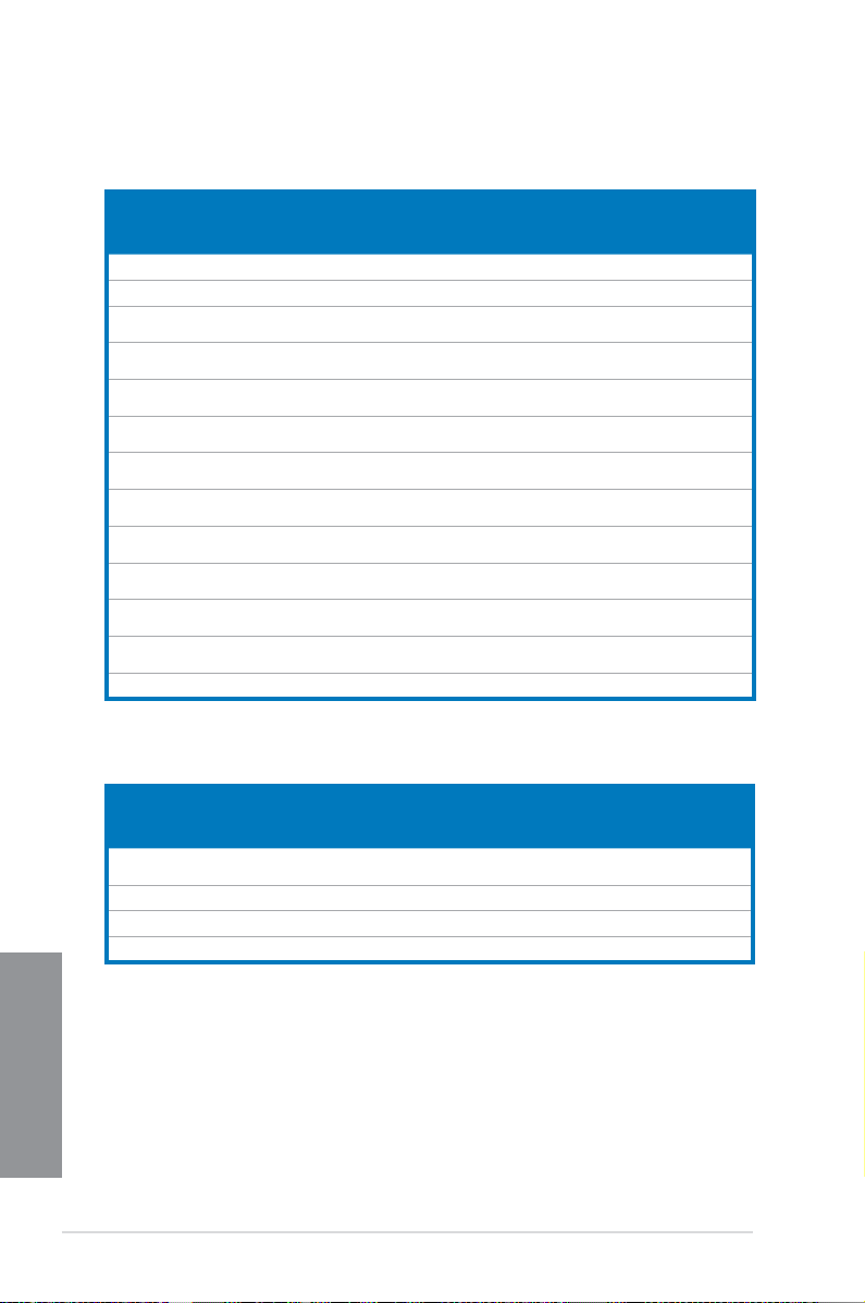
4. Q-Code LEDs
The Q-Code LED design provides you with a 2-digit error code that displays the system
status. Refer to the Q-Code table on the next page for details.
Q-Code table
Code Description
00 Not used
01 Power on. Reset type detection (soft/hard).
02 AP initialization before microcode loading
03 System Agent initialization before microcode loading
04 PCH initialization before microcode loading
06 Microcode loading
07 AP initialization after microcode loading
08 System Agent initialization after microcode loading
09 PCH initialization after microcode loading
0B Cache initialization
0C – 0D Reserved for future AMI SEC error codes
0E Microcode not found
0F Microcode not loaded
10 PEI Core is started
(continued on the next page)
ASUS MAXIMUS V FORMULA Series
Chapter 1
1-29
Page 48

Q-Code table
Code Description
11 – 14 Pre-memory CPU initialization is started
15 – 18 Pre-memory System Agent initialization is started
19 – 1C Pre-memory PCH initialization is started
2B – 2F Memory initialization
30 Reserved for ASL (see ASL Status Codes section below)
31 Memory Installed
32 – 36 CPU post-memory initialization
37 – 3A Post-Memory System Agent initialization is started
3B – 3E Post-Memory PCH initialization is started
4F DXE IPL is started
50 – 53
54 Unspecied memory initialization error
55 Memory not installed
56 Invalid CPU type or Speed
57 CPU mismatch
58 CPU self test failed or possible CPU cache error
59 CPU micro-code is not found or micro-code update is failed
00 Not used
01 Power on. Reset type detection (soft/hard).
02 AP initialization before microcode loading
03 System Agent initialization before microcode loading
04 PCH initialization before microcode loading
06 Microcode loading
07 AP initialization after microcode loading
08 System Agent initialization after microcode loading
Chapter 1
09 PCH initialization after microcode loading
0B Cache initialization
0C – 0D Reserved for future AMI SEC error codes
0E Microcode not found
Memory initialization error. Invalid memory type or incompatible memory
speed
1-30
(continued on the next page)
Chapter 1: Product introduction
Page 49

Code Description
0F Microcode not loaded
10 PEI Core is started
11 – 14 Pre-memory CPU initialization is started
15 – 18 Pre-memory System Agent initialization is started
19 – 1C Pre-memory PCH initialization is started
2B – 2F Memory initialization
30 Reserved for ASL (see ASL Status Codes section below)
31 Memory Installed
32 – 36 CPU post-memory initialization
37 – 3A Post-Memory System Agent initialization is started
3B – 3E Post-Memory PCH initialization is started
4F DXE IPL is started
50 – 53
54 Unspecied memory initialization error
55 Memory not installed
56 Invalid CPU type or Speed
57 CPU mismatch
58 CPU self test failed or possible CPU cache error
59 CPU micro-code is not found or micro-code update is failed
5A Internal CPU error
5B
5C – 5F
E0
E1
E2
E3
E4 – E7
E8
E9
Memory initialization error. Invalid memory type or incompatible memory
speed
Reset PPI is not available
Reserved for future AMI error codes
S3 Resume is stared (S3 Resume PPI is called by the DXE IPL)
S3 Boot Script execution
Video repost
OS S3 wake vector call
Reserved for future AMI progress codes
S3 Resume Failed
S3 Resume PPI not Found
(continued on the next page)
ASUS MAXIMUS V FORMULA Series
Chapter 1
1-31
Page 50

Code Description
EA S3 Resume Boot Script Error
EB S3 OS Wake Error
EC – EF Reserved for future AMI error codes
F0 Recovery condition triggered by rmware (Auto recovery)
F1 Recovery condition triggered by user (Forced recovery)
F2 Recovery process started
F3 Recovery rmware image is found
F4 Recovery rmware image is loaded
F5 – F7 Reserved for future AMI progress codes
F8 Recovery PPI is not available
F9 Recovery capsule is not found
FA Invalid recovery capsule
FB – FF Reserved for future AMI error codes
60 DXE Core is started
61 NVRAM initialization
62 Installation of the PCH Runtime Services
63 – 67 CPU DXE initialization is started
68 PCI host bridge initialization
69 System Agent DXE initialization is started
6A System Agent DXE SMM initialization is started
6B – 6F System Agent DXE initialization (System Agent module specic)
70 PCH DXE initialization is started
71 PCH DXE SMM initialization is started
72
73 – 77
78
Chapter 1
79
7A – 7F
90
91
PCH devices initialization
PCH DXE Initialization (PCH module specic)
ACPI module initialization
CSM initialization
Reserved for future AMI DXE codes
Boot Device Selection (BDS) phase is started
Driver connecting is started
(continued on the next page)
1-32
Chapter 1: Product introduction
Page 51

Code Description
92 PCI Bus initialization is started
93 PCI Bus Hot Plug Controller Initialization
94 PCI Bus Enumeration
95 PCI Bus Request Resources
96 PCI Bus Assign Resources
97 Console Output devices connect
98 Console input devices connect
99 Super IO Initialization
9A USB initialization is started
9B USB Reset
9C USB Detect
9D USB Enable
9E – 9F Reserved for future AMI codes
A0 IDE initialization is started
A1 IDE Reset
A2 IDE Detect
A3 IDE Enable
A4 SCSI initialization is started
A5 SCSI Reset
A6 SCSI Detect
A7 SCSI Enable
A8 Setup Verifying Password
A9 Start of Setup
AA
AB
AC
AD
AE
AF
B0
Reserved for ASL (see ASL Status Codes section below)
Setup Input Wait
Reserved for ASL (see ASL Status Codes section below)
Ready To Boot event
Legacy Boot event
Exit Boot Services event
Runtime Set Virtual Address MAP Begin
(continued on the next page)
Chapter 1
ASUS MAXIMUS V FORMULA Series
1-33
Page 52

Code Description
B1 Runtime Set Virtual Address MAP End
B2 Legacy Option ROM Initialization
B3 System Reset
B4 USB hot plug
B5 PCI bus hot plug
B6 Clean-up of NVRAM
B7 Conguration Reset (reset of NVRAM settings)
B8– BF Reserved for future AMI codes
D0 CPU initialization error
D1 System Agent initialization error
D2 PCH initialization error
D3 Some of the Architectural Protocols are not available
D4 PCI resource allocation error. Out of Resources
D5 No Space for Legacy Option ROM
D6 No Console Output Devices are found
D7 No Console Input Devices are found
D8 Invalid password
D9 Error loading Boot Option (LoadImage returned error)
DA Boot Option is failed (StartImage returned error)
DB Flash update is failed
DC Reset protocol is not available
Chapter 1
1-34
Chapter 1: Product introduction
Page 53

ACPI/ASL Checkpoints
Code Description
0x01 System is entering S1 sleep state
0x02 System is entering S2 sleep state
0x03 System is entering S3 sleep state
0x04 System is entering S4 sleep state
0x05 System is entering S5 sleep state
0x10 System is waking up from the S1 sleep state
0x20 System is waking up from the S2 sleep state
0x30 System is waking up from the S3 sleep state
0x40 System is waking up from the S4 sleep state
0xAC System has transitioned into ACPI mode. Interrupt controller is in PIC mode.
0xAA System has transitioned into ACPI mode. Interrupt controller is in APIC mode.
ASUS MAXIMUS V FORMULA Series
Chapter 1
1-35
Page 54

1.2.9 Internal connectors
1. Intel® Z77 Serial ATA 6.0 Gb/s connectors (7-pin SATA6G_1/2 [red])
These connectors connect to Serial ATA 6.0 Gb/s hard disk drives via Serial ATA 6.0
Gb/s signal cables.
If you installed Serial ATA hard disk drives, you can create a RAID 0, 1, 5, and 10
conguration with the Intel® Rapid Storage Technology through the onboard Intel® Z77
chipset.
Chapter 1
1-36
• These connectors are set to [AHCI Mode] by default. If you intend to create a Serial
ATA RAID set using these connectors, set the SATA Mode item in the BIOS to [RAID
Mode]. Refer to section 3.5.3 SATA Conguration for details.
• Before creating a RAID set, refer to section
bundled in the motherboard support DVD.
• When using NCQ, set the SATA Mode in the BIOS to [
3.5.3 SATA Conguration for details.
• You must install Windows
ATA hard disk drives. The Serial ATA RAID feature is available only if you are using
Windows® XP SP3 or later versions.
®
XP Service Pack 3 or later versions before using Serial
5.1 RAID congurations or the manual
AHCI Mode]. Refer to section
Chapter 1: Product introduction
Page 55

2. Intel® Z77 Serial ATA 3.0 Gb/s connectors (7-pin SATA3G_34/5 [black])
These connectors connect to Serial ATA 3.0 Gb/s hard disk drives and optical disc
drives via Serial ATA 3.0 Gb/s signal cables.
If you installed Serial ATA hard disk drives, you can create a RAID 0, 1, 5, and 10
conguration with the Intel® Rapid Storage Technology through the onboard Intel® Z77
chipset.
• These connectors are set to [AHCI Mode] by default. If you intend to create a Serial
ATA RAID set using these connectors, set the SATA Mode item in the BIOS to [RAID
Mode]. Refer to section 3.5.3 SATA Conguration for details.
• Before creating a RAID set, refer to section
bundled in the motherboard support DVD.
• When using NCQ, set the SATA Mode in the BIOS to [
3.5.3 SATA Conguration for details.
• You must install Windows
ATA hard disk drives. The Serial ATA RAID feature is available only if you are using
Windows® XP SP3 or later versions.
®
XP Service Pack 3 or later versions before using Serial
5.1 RAID congurations or the manual
AHCI Mode]. Refer to section
ASUS MAXIMUS V FORMULA Series
Chapter 1
1-37
Page 56

3. Asmedia® Serial ATA 6.0 Gb/s connectors (7-pin SATA6G_E12/E34 [red])
These connectors connect to Serial ATA 6.0 Gb/s hard disk drives via Serial ATA 6.0
Gb/s signal cables.
You must install Windows® XP Service Pack 3 or later versions before using Serial ATA
hard disk drives.
Chapter 1
1-38
Chapter 1: Product introduction
Page 57

4. USB 3.0 connector (20-1 pin USB3_12)
This connector is for the additional USB 3.0 ports, and complies with the USB 3.0
specicaton that supports up to 480 MBps connection speed. If the USB 3.0 front panel
cable is available from your system chassis, with this USB 3.0 connector, you can have
a front panel USB 3.0 solution.
Due to Intel® limitations, USB3_12 connector ports run at USB 3.0 speed rate under
Windows® 7 or later versions.
5. Digital audio connector (4-1 pin SPDIF_OUT)
This connector is for an additional Sony/Philips Digital Interface (S/PDIF) port. Connect
the S/PDIF Out module cable to this connector, then install the module to a slot
opening at the back of the system chassis.
The S/PDIF module is purchased separately.
ASUS MAXIMUS V FORMULA Series
Chapter 1
1-39
Page 58

6. USB 2.0 connectors (10-1 pin USB56; USB78)
These connectors are for USB 2.0 ports. Connect the USB module cable to any of
these connectors, then install the module to a slot opening at the back of the system
chassis. These USB connectors comply with USB 2.0 specication that supports up to
48 MBps connection speed.
Never connect a 1394 cable to the USB connectors. Doing so will damage the
motherboard!
You can connect the front panel USB cable to the ASUS Q-Connector (USB, blue) rst, and
then install the Q-Connector (USB) to the USB connector onboard if your chassis supports
front panel USB ports.
Chapter 1
1-40
The USB 2.0 module is purchased separately.
Chapter 1: Product introduction
Page 59

7. CPU, chassis, and optional fan connectors
(4-pin CPU_FAN; 4-pin CPU_OPT; 4-pin CHA_FAN1-3; OPT_FAN1-3)
Connect the fan cables to the fan connectors on the motherboard, ensuring that the
black wire of each cable matches the ground pin of the connector.
DO NOT forget to connect the fan cables to the fan connectors. Insufcient air ow inside
the system may damage the motherboard components. These are not jumpers! Do not
place jumper caps on the fan connectors!
• The CPU_FAN connector supports the CPU fan of maximum 1A (12 W) fan power.
• If you install two VGA cards, we recommend that you plug the rear chassis fan cable
to the motherboard connector labeled CHA_FAN1, CHA_FAN2, CHA_FAN3 for better
thermal environment.
ASUS MAXIMUS V FORMULA Series
Chapter 1
1-41
Page 60

8. Front panel audio connector (10-1 pin AAFP)
This connector is for a chassis-mounted front panel audio I/O module that supports
either HD Audio or legacy AC`97 audio standard. Connect one end of the front panel
audio I/O module cable to this connector.
• We recommend that you connect a high-denition front panel audio module to this
connector to avail of the motherboard’s high-denition audio capability.
• If you want to connect a high-denition or an AC’97 front panel audio module to this
connector, set the Front Panel Type item in the BIOS setup to [HD] or [AC97].
Chapter 1
1-42
Chapter 1: Product introduction
Page 61

9. ATX power connectors (24-pin EATXPWR; 8-pin EATX12V; 4-pin EZ PLUG)
These connectors are for ATX power supply plugs. The power supply plugs are
designed to t these connectors in only one orientation. Find the proper orientation and
push down rmly until the connectors completely t.
• For a fully congured system, we recommend that you use a power supply unit
(PSU) that complies with ATX 12 V Specication 2.0 (or later version) and provides a
minimum power of 350 W.
• Do not forget to connect the 4-pin/8-pin EATX12 V power plug. Otherwise, the system
will not boot.
• We recommend that you use a PSU with a higher power output when conguring a
system with more power-consuming devices. The system may become unstable or
may not boot up if the power is inadequate.
• If you want to use two or more high-end PCI Express x16 cards, use a PSU with
1000W power or above to ensure the system stability.
• If you are uncertain about the minimum power supply requirement for your system,
refer to the Recommended Power Supply Wattage Calculator at http://support.asus.
com/PowerSupplyCalculator/PSCalculator.aspx?SLanguage=en-us for details.
ASUS MAXIMUS V FORMULA Series
Chapter 1
1-43
Page 62

10. System panel connector (20-8 pin PANEL)
This connector supports several chassis-mounted functions.
• System power LED (2-pin PLED)
This 2-pin connector is for the system power LED. Connect the chassis power LED
cable to this connector. The system power LED lights up when you turn on the system
power, and blinks when the system is in sleep mode.
• Hard disk drive activity LED (2-pin IDE_LED)
This 2-pin connector is for the HDD Activity LED. Connect the HDD Activity LED cable
to this connector. The IDE LED lights up or ashes when data is read from or written to
the HDD.
• System warning speaker (4-pin SPEAKER)
This 4-pin connector is for the chassis-mounted system warning speaker. The speaker
allows you to hear system beeps and warnings.
• ATX power button/soft-off button (2-pin PWRSW)
This connector is for the system power button. Pressing the power button turns
the system on or puts the system in sleep or soft-off mode depending on the BIOS
settings. Pressing the power switch for more than four seconds while the system is ON
turns the system OFF.
• Reset button (2-pin RESET)
This 2-pin connector is for the chassis-mounted reset button for system reboot without
turning off the system power.
Chapter 1
1-44
Chapter 1: Product introduction
Page 63

11. TPM connector (20-1 pin TPM)
This connector supports a Trusted Platform Module (TPM) system, which securely
store keys, digital certicates, passwords and data. A TPM system also helps enhance
network security, protect digital identities, and ensures platform integrity.
12. Thermal sensor cable connectors (2-pin OPT_TEMP1/2/3)
These connectors are for temperature monitoring. Connect the thermal sensor cables
to these connectors and place the other ends to the devices which you want to monitor
the temperature. The optional fan 1/2/3 can work with the temperature sensors for a
better cooling effect.
You must enable the OPT FAN 1/2/3 overheat protection in BIOS if you connect the
thermal sensor cables to these connectors.
The thermal sensor cables are purchased separately.
ASUS MAXIMUS V FORMULA Series
Chapter 1
1-45
Page 64

13. ROG Logo LED connector (3-pin ROG)
This connector is for the box (labeled Republic of Gamers) on the heatpipe assembly.
Connect the box’s cable, and it lights up when you turn on the system.
Chapter 1
1-46
Chapter 1: Product introduction
Page 65

1.2.10 Fusion Thermo
Fusion Thermo is an exclusive ROG heatsink that provides air-cooling and water cooling
elements, generating cooler ventilation for your motherboard.
Fusion Thermo contains 100% copper water channel with electro-plated nickel barbs for
cooling purpose. It also has an integrated heatpipe wrapped in air-cooling ns that absorbs
heat and helps dissipate it throughout the system.
With Fusion Thermo, you have a hybrid air and water cooling system for an optimal cooling
performance.
Nickel barb
• The Fusion Thermo’s nickel barbs’ outer diameter measure 3/8 inch (10mm). We
recommend that you install a 3/8 inch ID tubing, and lock both ends with the bundled
clamps that came with the water cooling kit.
• We recommend that you route the water cooling kit from the CPU water block to the
Fusion Thermo zone.
• We recommend that you separate the VGA water cooling system and the CPU/VRM
water cooling system for an optimal cooling result.
• Ensure to keep the chassis ventilation airow in one direction.
• Refer to the technical documentation of your water cooling kit for assembly
instructions.
Nickel barb
ASUS MAXIMUS V FORMULA Series
Chapter 1
1-47
Page 66

Chapter 1
1-48
Chapter 1: Product introduction
Page 67

Basic Installation
2.1 Building your PC system
2.1.1 Motherboard installation
The diagrams in this section are for reference only. The motherboard layout may vary with
models, but the installation steps are the same for all models.
1. Install the ASUS Q-Shield to the chassis rear I/O panel.
1
2
ASUS MAXIMUS V FORMULA Series
Chapter 2
2-1
Page 68

2. Place the motherboard into the chassis, ensuring that its rear I/O ports are aligned to
the chassis’ rear I/O panel.
2
Chapter 2
2-2
Chapter 2: Getting started
Page 69

3. Place ten screws into the holes indicated by circles to secure the motherboard to the
chassis.
3
DO NOT overtighten the screws! Doing so can damage the motherboard.
ASUS MAXIMUS V FORMULA Series
Chapter 2
2-3
Page 70

2.1.2 CPU installation
A
B
A
B
C
The LGA1156 CPU is not compatible with the LGA1155 socket. DO NOT install a LGA1156
CPU on the LGA1155 socket.
1
2
4
Chapter 2
3
5
2-4
Chapter 2: Getting started
Page 71

2.1.3 CPU heatsink and fan assembly installation
Apply the Thermal Interface Material to the
CPU heatsink and CPU before you install
the heatsink and fan if necessary.
To install the CPU heatsink and fan assembly
1
A
B
B
A
3 4
2
ASUS MAXIMUS V FORMULA Series
Chapter 2
2-5
Page 72

To uninstall the CPU heatsink and fan assembly
1
2
A
B
B
A
Chapter 2
2-6
Chapter 2: Getting started
Page 73

2.1.4 DIMM installation
1
2
3
To remove a DIMM
B
ASUS MAXIMUS V FORMULA Series
A
Chapter 2
2-7
Page 74

2.1.5 ATX Power connection
1
2
OR OR
Chapter 2
2-8
Chapter 2: Getting started
Page 75

2.1.6 SATA device connection
1
OR
2
OR
ASUS MAXIMUS V FORMULA Series
Chapter 2
2-9
Page 76

2.1.7 Front I/O Connector
IDE_LED
POWER SW
RESET SW
IDE_LED-
IDE_LED+
PWR
Reset
Ground
Ground
To install ASUS Q-Connector
1
2
To install USB 2.0 connector To install front panel audio connector
AAFP
To install USB 3.0 connector
Chapter 2
2-10
USB 2.0
USB 3.0
Chapter 2: Getting started
Page 77

2.1.8 Expansion Card installation
To install PCIe x16 cards
To install PCIe x1 cards
ASUS MAXIMUS V FORMULA Series
Chapter 2
2-11
Page 78

2.1.9 mPCIe Combo installation
The mPCIe Combo is a mini card that allows you to add an mPCIe module and an mSATA
module into your motherboard.
• The mPCIe Combo supports half-sized mPCIe modules (26.8mm x 30mm) only.
• The mPCIe Combo supports full-sized and hald-sized mSATA modules. The
suggested sizes are from 50.8mm x 30mm to 26.8mm x 30mm.
• The mPCIe and mSATA modules are purchased separately.
• The Wi-Fi module is already installed to the mPCIe Combo card, and will only be
available in certain motherboard models.
Installing the mPCIe Wi-Fi module
To install the mPCIe Wi-Fi module:
1. Remove both screws from the side of the MINI_PCIE slot.
2. Insert the mPCIe Wi-Fi module.
Chapter 2
2-12
The mPCIe Wi-Fi module ts in one orientation only.
Chapter 2: Getting started
Page 79

3. Press down the Wi-Fi module, and secure it in place by using the screws removed
earlier.
DO NOT overtighten the screws to prevent damage to the mPCIe Wi-Fi module or mPCIe
Combo.
Be sure to install the Bluetooth driver before installing the Wi-Fi GO! software.
4. Remove the screw beside the 26-pin connector.
ASUS MAXIMUS V FORMULA Series
Chapter 2
2-13
Page 80

5. Locate the mPCIe_Combo connector on the motherboard. Align and insert the mPCIe
Combo on the connector.
• The mPCIe Combo ts in one orientation only.
• Insert the mPCIe Combo with caution to prevent damage to the module, or the
mCPIe_Combo connector pins, or the motherboard.
6. Secure the mPCIe Combo in place with the screws removed in step 4.
Chapter 2
2-14
Chapter 2: Getting started
Page 81

7. Remove the bolt from the Wi-Fi antenna connector. Leave the washer on the
antenna connector
bolt
washer
I/O Shield
connector.
8. Insert the connector into the I/O shield’s Wi-Fi port hole.
Ensure that the washer is placed between the connector and the back of the I/O shield.
The Wi-Fi antenna and its cables are purchased separately.
9. Re-attach the bolt on the connector.
10. Connect the opposite end of the Wi-Fi antenna connector to the pins located on the
mPCIe Wi-Fi card.
ASUS MAXIMUS V FORMULA Series
Chapter 2
2-15
Page 82

Installing the mSATA module
B
A
A
2
3
To install the mSATA module:
1. Unlock the mSATA clip.
2. Insert the mSATA card into the MSATA slot.
The mSATA card ts in one orientation only.
3. Lock the mSATA clip.
Chapter 2
2-16
Chapter 2: Getting started
Page 83

4. Remove the screw near the 26-pin connector.
5. Locate the mPCIe_Combo connector on the motherboard. Align and insert the mPCIe
Combo on the connector.
• The mPCIe Combo ts in one orientation only.
• Insert the mPCIe with caution to prevent damage to the module, or the mPCIe_Combo
connector pins, or the motherboard.
ASUS MAXIMUS V FORMULA Series
Chapter 2
2-17
Page 84

6. Secure the mPCIe Combo in place with the screw removed in step 4.
Chapter 2
2-18
Chapter 2: Getting started
Page 85

2.2 BIOS update utility
2.2.1 USB BIOS Flashback
USB BIOS Flashback allows you to easily update the BIOS without entering the existing
BIOS or operating system. Simply insert a USB storage device to the USB port, press the
USB BIOS Flashback button for three seconds, and the BIOS is updated automatically.
To use USB BIOS Flashback:
1. Download the latest BIOS le from the ASUS website
2. Extract and rename the BIOS image le to
3. Copy
M5F.CAP to the root directory of the USB ash disk drive.
4. Turn off the system and insert the USB storage device to the ROG Connect port.
5. Press the ROG Connect button and release when a ashing light appears, which
indicates that the BIOS Flashback function is enabled.
6. Wait until the light goes out, indicating that the BIOS updating process is completed.
M5F.CAP.
USB BIOS Flashback button
For more BIOS update utilities in BIOS setup, refer to the section Updating BIOS in
Chapter 3.
• Do not unplug portable disk, power system, or press the CLR_CMOS button while
BIOS update is ongoing, otherwise update will be interrupted. In case of interruption,
please follow the steps again.
• Updating BIOS may have risks. If the BIOS program is damaged during the process
and results to the system’s failure to boot up, please contact your local ASUS Service
Center.
ASUS MAXIMUS V FORMULA Series
USB BIOS Flashback port
Chapter 2
2-19
Page 86

2.3 Motherboard rear and audio connections
2.3.1 Rear I/O connection
Rear panel connectors
1. External SATA ports
2. Optical S/PDIF OUT port
3. LAN (RJ-45) port*
4. Clear CMOS button
5. ROG Connect button
6. USB 2.0 ports
7. USB 2.0 port, also ROG Connect port
Chapter 2
8. ASMedia USB 3.0 ports, support ASUS USB 3.0 Boost UASP Mode
9. HDMI port
10. DisplayPort
11. Intel USB 3.0 ports, support ASUS USB 3.0 Boost Turbo Mode.
12. Optical S/PDIF IN port
13. Audio I/O ports**
* and ** : Refer to the tables on the next page for LAN port LEDs, and audio port denitions.
2-20
Chapter 2: Getting started
Page 87

• Due to USB 3.0 controller limitation, USB 3.0 devices can only be used under
Windows® OS environment and after the USB 3.0 driver installation.
• USB 3.0 devices can only be used as data storage only.
• We strongly recommend that you connect USB 3.0 devices to USB 3.0 ports for faster
and better performance for your USB 3.0 devices.
• Due to XCHI controller structure, we recommend to manually install your USB 3.0
driver twice when installing the operating system from the USB 3.0 optical drive.
* LAN ports LED indications
Activity Link LED Speed LED
Status Description Status Description
OFF No link OFF 10 Mbps connection
ORANGE Linked ORANGE 100 Mbps connection
BLINKING Data activity GREEN 1 Gbps connection
** Audio 2, 4, 6 or 8-channel conguration
Port Headset
2-channel
Light Blue Line In Line In Line In Line In
Lime Line Out Front Speaker Out Front Speaker Out Front Speaker Out
Pink Mic In Mic In Mic In Mic In
Orange – – Center/Subwoofer Center/Subwoofer
Black – Rear Speaker Out Rear Speaker Out Rear Speaker Out
4-channel 6-channel 8-channel
2.3.2 Audio I/O connections
Audio I/O ports
ASUS MAXIMUS V FORMULA Series
Chapter 2
2-21
Page 88

Connect to Headphone and Mic
Connect to Stereo Speakers
Connect to 2.1 channel Speakers
Chapter 2
2-22
Chapter 2: Getting started
Page 89

Connect to 4.1 channel Speakers
Connect to 5.1 channel Speakers
ASUS MAXIMUS V FORMULA Series
Chapter 2
2-23
Page 90

Connect to 7.1 channel Speakers
When the DTS UltraPC II function is enabled, ensure to connect the rear speaker to the
gray port.
Chapter 2
2-24
Chapter 2: Getting started
Page 91

2.4 Starting up for the rst time
1. After making all the connections, replace the system case cover.
2. Ensure that all switches are off.
3. Connect the power cord to the power connector at the back of the system chassis.
4. Connect the power cord to a power outlet that is equipped with a surge protector.
5. Turn on the devices in the following order:
a. Monitor
b. External SCSI devices (starting with the last device on the chain)
c. System power
6. After applying power, the system power LED on the system front panel case lights up.
For systems with ATX power supplies, the system LED lights up when you press the
ATX power button. If your monitor complies with the “green” standards or if it has a
“power standby” feature, the monitor LED may light up or change from orange to green
after the system LED turns on.
The system then runs the power-on self tests (POST). While the tests are running, the
BIOS beeps (refer to the BIOS beep codes table) or additional messages appear on
the screen. If you do not see anything within 30 seconds from the time you turned on
the power, the system may have failed a power-on test. Check the jumper settings and
connections or call your retailer for assistance.
BIOS Beep Description
One short beep VGA detected
One continuous beep followed by two
short beeps then a pause (repeated)
One continuous beep followed by three
short beeps
One continuous beep followed by four
short beeps
Quick boot set to disabled
No keyboard detected
No memory detected
No VGA detected
Hardware component failure
7. At power on, hold down the <Delete> key to enter the BIOS Setup. Follow the
instructions in Chapter 3.
2.5 Turning off the computer
While the system is ON, press the power button for less than four seconds to put the system
on sleep mode or soft-off mode, depending on the BIOS setting. Press the power switch
for more than four seconds to let the system enter the soft-off mode regardless of the BIOS
setting.
ASUS MAXIMUS V FORMULA Series
Chapter 2
2-25
Page 92

Chapter 2
2-26
Chapter 2: Getting started
Page 93

BIOS setup
3
3.1 Knowing BIOS
The new ASUS UEFI BIOS is a Unied Extensible Interface that complies with UEFI
architecture, offering a user-friendly interface that goes beyond the traditional keyboard-
only BIOS controls to enable a more exible and convenient mouse input. You can easily
navigate the new UEFI BIOS with the same smoothness as your operating system. The
term “BIOS” in this user manual refers to “UEFI BIOS” unless otherwise specied.
BIOS (Basic Input and Output System) stores system hardware settings such as storage
device conguration, overclocking settings, advanced power management, and boot
device conguration that are needed for system startup in the motherboard CMOS. In
normal circumstances, the default BIOS settings apply to most conditions to ensure
optimal performance. DO NOT change the default BIOS settings except in the following
circumstances:
An error message appears on the screen during the system bootup and requests you to
•
run the BIOS Setup.
You have installed a new system component that requires further BIOS settings or
•
update.
Inappropriate BIOS settings may result to instability or boot failure. We strongly
recommend that you change the BIOS settings only with the help of a trained service
personnel.
When downloading or updating the BIOS le, rename it as MVF.CAP for this motherboard.
ASUS MAXIMUS V FORMULA Series
Chapter 3
3-1
Page 94

3.2 BIOS setup program
Use the BIOS Setup to update the BIOS or congure its parameters. The BIOS screen
include navigation keys and brief onscreen help to guide you in using the BIOS Setup
program.
Entering BIOS at startup
To enter BIOS Setup at startup:
• Press <Delete> during the Power-On Self Test (POST). If you do not press <Delete>,
POST continues with its routines.
Entering BIOS Setup after POST
To enter BIOS Setup after POST:
• Press <Ctrl>+<Alt>+<Delete> simultaneously.
• Press the reset button on the system chassis.
• Press the power button to turn the system off then back on. Do this option only if you
failed to enter BIOS Setup using the rst two options.
• The BIOS setup screens shown in this section are for reference purposes only, and
may not exactly match what you see on your screen.
• Ensure that a USB mouse is connected to your motherboard if you want to use the
mouse to control the BIOS setup program.
• If the system becomes unstable after changing any BIOS setting, load the default
settings to ensure system compatibility and stability. Select the Load Optimized
Defaults item under the Exit menu or press hotkey <F5>. See section 3.9 Exit Menu
for details.
• If the system fails to boot after changing any BIOS setting, try to clear the CMOS and
reset the motherboard to the default value. See section 1.2.6 Onboard buttons and
switches for information on how to erase the RTC RAM via the Clear CMOS button.
• The BIOS setup program does not support the bluetooth devices.
BIOS menu screen
The BIOS Setup program can be used under two modes: EZ Mode and Advanced Mode.
You can change modes from the Exit menu or from the Exit/Advanced Mode screen.
Chapter 3
3-2
Chapter 3: BIOS setup
Page 95

3.2.1 EZ Mode
By default, the EZ Mode screen appears when you enter the BIOS setup program. The EZ
Mode provides you an overview of the basic system information, and allows you to select
the display language, system performance mode and boot device priority. To access the
Advanced Mode, click Exit/Advanced Mode, then select Advanced Mode or press <F7> hot
key for the advanced BIOS settings.
The default screen for entering the BIOS setup program can be changed. Refer to the
Setup Mode item in section 3.7 Boot menu for details.
Displays the CPU/motherboard temperature,
CPU/5V/3.3V/12V voltage output, CPU/chassis/
power fan speed
Selects the Advanced
Mode functions
Displays the system properties of the
selected mode on the right hand side
Displays the Advanced
mode menus
Selects the boot device priority
Selects the display language of the
BIOS setup program
Exits the BIOS setup program without saving
the changes, saves the changes and resets the
system, or enters the Advanced Mode
Power Saving mode
Normal mode
Click to display all fan
speeds if available
Loads optimized default
settings
ASUS Optimal mode
• The boot device options vary depending on the devices you installed to the system.
• The
Boot Menu(F8) button is available only when the boot device is installed to the
system.
ASUS MAXIMUS V FORMULA Series
Chapter 3
3-3
Page 96

3.2.2 Advanced Mode
The Advanced Mode provides advanced options for experienced end-users to congure
the BIOS settings. The gure below shows an example of the Advanced Mode. Refer to the
following sections for the detailed congurations.
To access the Advanced Mode, click Exit, then select Advanced Mode or press F7 hotkey.
Menu items
Submenu item
Menu bar
Pop-up window
Conguration elds
Scroll bar
Menu bar
The menu bar on top of the screen has the following main items:
General help
Navigation keys
Main For changing the basic system conguration
Chapter 3
Extreme Tweaker For changing the overclocking settings
Advanced For changing the advanced system settings
Monitor
Boot For changing the system boot conguration
Tool For conguring options for special functions
Exit For selecting the exit options and loading default settings
3-4
For displaying the system temperature, power status, and changing
the fan settings.
Chapter 3: BIOS setup
Page 97

Menu items
The highlighted item on the menu bar displays the specic items for that menu. For example,
selecting Main shows the Main menu items.
The other items (Ai Tweaker, Advanced, Monitor, Boot, Tool, and Exit) on the menu bar have
their respective menu items.
Back button
This button appears when entering a submenu. Press <Esc> or use the USB mouse to click
this button to return to the previous menu screen.
Submenu items
A greater than sign (>) before each item on any menu screen means that the item has a
submenu. To display the submenu, select the item and press <Enter>.
Pop-up window
Select a menu item and press <Enter> to display a pop-up window with the conguration
options for that item.
Scroll bar
A scroll bar appears on the right side of a menu screen when there are items that do not t on
the screen. Press the Up/Down arrow keys or <Page Up> / <Page Down> keys to display the
other items on the screen.
Navigation keys
At the bottom right corner of the menu screen are the navigation keys for the BIOS setup
program. Use the navigation keys to select items in the menu and change the settings.
General help
At the top right corner of the menu screen is a brief description of the selected item. Use
<F12> key to capture the BIOS screen and save it to the removable storage device.
Conguration elds
These elds show the values for the menu items. If an item is user-congurable, you can
change the value of the eld opposite the item. You cannot select an item that is not
user-congurable.
A congurable eld is highlighted when selected. To change the value of a eld, select it and
press <Enter> to display a list of options.
ASUS MAXIMUS V FORMULA Series
Chapter 3
3-5
Page 98

3.3 Extreme Tweaker menu
The Extreme Tweaker menu items allow you to congure overclocking-related items.
Be cautious when changing the settings of the Ai Tweaker menu items. Incorrect eld
values can cause the system to malfunction.
The conguration options for this section vary depending on the CPU and DIMM model you
installed on the motherboard.
Scroll down to display other BIOS items.
Chapter 3
3-6
Chapter 3: BIOS setup
Page 99

Load Gamers’ OC Prole
Press <Enter> and select Yes to load the Gamers’ OC prole to suit extreme overclocking.
CPU Level Up [Disabled]
Allows you to select a CPU level, and the related parameters will be automatically adjusted
according to the selected CPU level.
Conguration options: [Disabled] [Auto] [X.XXXG]
Ai Overclock Tuner [Auto]
Allows you to select the CPU overclocking options to achieve the desired CPU internal
frequency. Select any of these preset overclocking conguration options:
[Auto] Loads the optimal settings for the system.
[Manual] Allows you to individually set overclocking parameters.
[X.M.P.] If you install memory modules supporting the eXtreme Memory Prole
eXtreme Memory Profile
This item appears only when you set the Ai Overclocking Tuner item to [X.M.P.] and
allows you to select the X.M.P. mode supported by your memory module.
Conguration options: [Prole #1] [ Prole #2]
BCLK/PEG Frequency [XXX]
This item appears only when you set the Ai Overclocking Tuner item to [Manual]. It
allows you to adjust the CPU and VGA frequency to enhance the system performance.
Use the <+> and <-> keys to adjust the value. You can also key in the desired value
using the numeric keypad. The values range from 80.0MHz to 300.0MHz.
(X.M.P.) Technology, choose this item to set the proles supported by your
memory modules for optimizing the system performance.
The [X.M.P.] conguration option appears only when you install memory modules
supporting the eXtreme Memory Prole(X.M.P.) Technology.
Memory Frequency [Auto]
Allows you to set the memory operating frequency.
Conguration options: [Auto] [DDR3-800MHz] [DDR3-1066MHz] [DDR3-1333MHz] [DDR31600MHz] [DDR3-1866MHz] [DDR3-2133MHz] [DDR3-2400MHz]
Selecting a very high memory frequency may cause the system to become unstable! If this
happens, revert to the default setting.
Xtreme Tweaking [Disabled]
This item may help improve some benchmarks performance.
Conguration options: [Disabled] [Enabled]
ASUS MAXIMUS V FORMULA Series
Chapter 3
3-7
Page 100

EPU Power Saving Mode [Disabled]
Allows you to enable or disable the EPU power saving function.
Conguration options: [Disabled] [Enabled]
EPU Setting [Auto]
This item only appears when you set the EPU Power Saving Mode to [Enabled]. It
allows you to set the EPU setting to power saving modes.
Conguration options: [Auto] [Light Power Saving Mode] [Medium Power Saving Mode]
[Max Power Saving Mode]
DRAM Timing Control
The sub-items in this menu allow you to set the DRAM timing control features. Use the <+>
and <-> keys to adjust the value. To restore the default setting, type [auto] using the keyboard
and press the <Enter> key.
Memory Presets
Allows you to congure a memory preset for different memory modules.
Chapter 3
Changing the values in this menu may cause the system to become unstable! If this
happens, revert to the default settings.
Load Elpida Hyper Prole
Allows you to load a timing prole for Elpida Hyper chipset.
Conguration options: [Yes] [No]
Load Tight 2x2GB Elpida BBSE Prole
Allows you to load a tight timing prole for 2x2GB Elpida BBSE chipset.
Conguration options: [Yes] [No]
Load Tight 4x2GB Elpida BBSE Prole
Allows you to load a tight timing prole for 4x2GB Elpida BBSE chipset.
Conguration options: [Yes] [No]
Load Loose Elpida BBSE Prole
Allows you to load a loose timing prole for Elpida BBSE chipset.
Conguration options: [Yes] [No]
Load Tight 2x2GB PSC Prole
Allows you to load a tight timing prole for 2x2GB PSC chipset.
Conguration options: [Yes] [No]
Load Tight 4x2GB PSC Prole
Allows you to load a tight timing prole for 4x2GB PSC chipset.
Conguration options: [Yes] [No]
Load Loose PSC Prole
Allows you to load a loose PSC prole for PSC chipset.
Conguration options: [Yes] [No]
3-8
Chapter 3: BIOS setup
 Loading...