

Page 1

DOCSIS Cable Modem
User’s Manual
Page 2

Product Name: Cable Modem
Manual Revision: 1.00 E580-X
Release Date: June 2000
2
Page 3

Contents
Introduction
Overview ........................................................................................................................... 4
Features ............................................................................................................................ 4
Package Contents ............................................................................................................. 4
Preparations
System Requirement.........................................................................................................5
Installing a Network Card .................................................................................................. 5
Installing the TCP/IP Protocol............................................................................................ 6
Changing TCP/IP Settings................................................................................................. 6
Checking if TCP/IP is already installed........................................................................... 6
Adding TCP/IP in Network properties ............................................................................. 6
Using the Cable Modem
Front Panel........................................................................................................................ 7
Rear Panel ........................................................................................................................ 8
Installing the Cable Modem............................................................................................... 9
Powering Up.................................................................................................................... 10
Multiple Client Configuration ........................................................................................... 10
Product Certifications
FCC (Federal Communications Commission Statement) ............................................... 11
UL.................................................................................................................................... 11
CE ................................................................................................................................... 11
Product Specifications
Software Specifications ................................................................................................... 12
RF Receiver/Transmitter Specifications .......................................................................... 13
Hardware Specifications.................................................................................................. 14
3
Page 4

Introduction
Overview
Features
Thank you for purchasing the DOCSIS-compliant cable modem. This cable modem delivers
the highest performance in data over cable technology. Ideal for home and small business
users, this easy-to-use communication device offers reliable connectivity as well as remarkable data transfer rates--up to 43Mbps downstream and 10Mbps upstream, 100 times faster
than a 56K dial-up modem. Once the cable modem is powered up, you are online to enjoy
real-time 3D animation, video conferencing, and perform other data intensive operations.
• MCNS DOCSIS 1.0 compliant
• Support for 6MHz downstream and 200K-3200KHz upstream cable channel bandwidth
• Peak data transfer rates of 38Mbps (64QAM) and 42Mbps (256QAM)
• Auto detection of 64QAM or 256QAM
• Network management protocol support for SNMPv1/v2c and DOCSIS 1.0 MIBs
• Data Encryption Standard (DES) and Baseline Privacy Interface (BPI) compliant
• Easy installation and operation
• Self-diagnoses available through front panel LEDs
• Software upgradeable
Package
Contents
PB
• Low power consumption with a maximum of 10Watts
• Stylish, compact design; horizontal or vertical standing
(1) DOCSIS Cable Modem (1) CAT.5 Ethernet cable (RJ-45)
(1) AC power adapter (1) User’s Manual
Page 5
Preparations
System
Requirements
Installing a
Network Card
Before connecting the cable modem to your PC, make sure your system is equipped with a
LAN controller and supports the TCP/IP protocol.
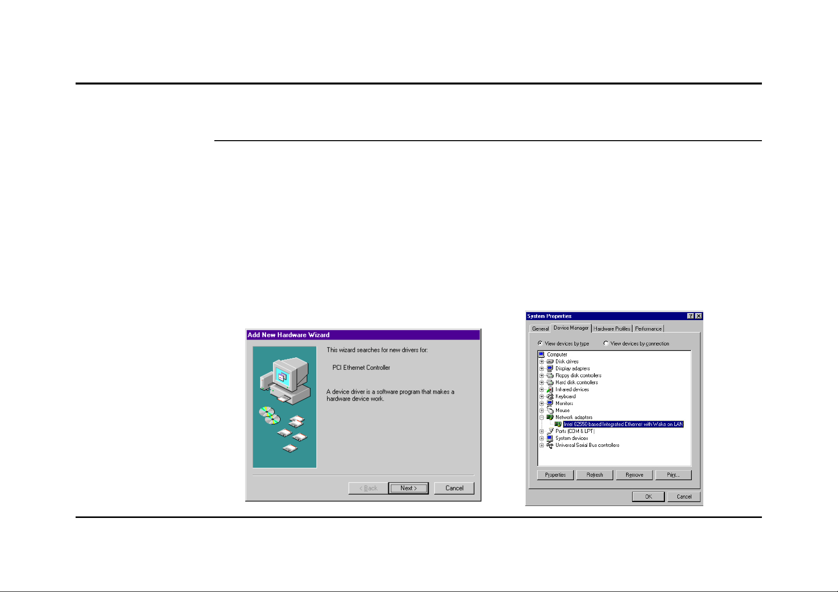
If your system does not have an embedded LAN controller, you must install a network
interface card as instructed below (assuming that you are using an Ethernet card under the
operating system of Windows 98):
1. Install the PCI-L101 card on your
motherboard.
2. Power up your PC and follow the Add
New Hardware Wizard’s instructions to
install the driver . When asked to restart
your computer at the end of the installation, click Yes.
3. After restarting the system, right-click
My Computer on the desktop, select
Properties, click the Device Manager
tab, and then double-click Network
adapters to confirm that the Ethernet
driver is properly installed.
5
Page 6

Preparations
Installing the
TCP/IP
Protocol
• Checking if TCP/IP is already installed
1. Click the Start button on the
desktop. In the Settings menu, select
Control Panel
Double-click the Network icon
• Adding TCP/IP in Network properties
1. Click Add.
.
.
2. Double-click Protocol.
2. In the list of installed network compo-
nents try to find the TCP/IP protocol. It
may be followed by the name of the
Ethernet controller. If you cannot locate
anything that begins with TCP/IP, install
it as described below.
3. Select Microsoft from the
manufacturers. In the list
of network protocols
browse to TCP/IP and
then double-click it.
Changing
TCP/IP Settings
PB
.
After the TCP/IP protocol is installed, restart your computer and consult the installation
guide provided by your cable operator to complete TCP/IP configurations.
Page 7

Using the Cable Modem
Front Panel
12345
POWER STATUS TESTCABLE PC
LED Indicator State Description
1. Power LED
ON Modem is powered ON
OFF Modem is powered OFF
2. Status LED ON Modem successfully registered on cable operator’s network
Flashing Modem is registering on cable operator’s network
OFF
(While Cable Link LED is flashing) searching for downstream channel
3. Cable Link LED ON Normal operation
Flashing (
Flashing (
OFF ––
While Status LED is ON) data streaming down
While Status LED is OFF) searching for downstream channel
4. PC Link LED ON LAN and PC connect successfully
Flashing Data transmitting between LAN and PC
OFF No connection between LAN and PC
5. Test ON Error (Resetting the cable modem may help; if not, contact
customer support)
OFF Normal operation
7
Page 8

Using the Cable Modem
Rear Panel
1. DC +5V/2A Power Input Jack
The provided power adapter converts AC power to DC power for use with this jack. Power
supplied through this jack will supply power to the cable modem.
2. RF Connector
The connector may be located right next to the power input jack or the serial port. The FType female connector allows cable data communication between the cable modem and
the cable service provider through a coaxial cable.
3. Serial Port
The 9-pin D-sub serial port supports the RS-232 terminal interface for advanced cable
modem management.
1 2 3 4 65
DC+5V/2A ResetCable Console USB 10/100-BaseT
PB
4. Reset Switch
The reset button, when pressed, resets the cable modem without the need to unplug the
power cord.
5. USB Port (optional)
The optional USB port allows the modem to be connected to your computer through the
USB interface.
6. 10/100-BaseT LAN Port
The LAN port supports 10Base-T or 100Base-TX networks. This port allows your PC or
Ethernet hub to be connected to the cable modem through a CAT .5 twisted pair LAN cable.
Page 9

Using the Cable Modem
Splitter
Cable Modem
Installing the
Cable Modem
Take the following steps to accomplish the installation procedure:
1. Connect the cable TV coaxial cable to the input connector of a signal splitter.
2. Connect a coaxial cable from one of the output connectors on the splitter to the input
connector of your TV set.
3. Use another coaxial cable to connect the other output connector on the splitter and the
RF connector on the rear panel of the cable modem.
4. Connect the LAN cable from the LAN port on your computer to the LAN port on the
rear panel of the cable modem.
5. Connect the AC power adapter to the DC +5V/2A input jack on the rear panel of the
cable modem. Plug in the AC power adapter to an electrical outlet.
NOTE: If you are not using a television on the cable line, you may skip steps 1 to 3 and
connect the cable TV coaxial cable directly to the RF connector on the rear panel of the cable
modem.
Cable
Modem
DC+5V/2A ResetCable Console USB 10/100-BaseT
Step 3
Step 4Step 5
To Cable
Network
To Electrical Outlet
Rear Panel Connections
To Splitter or
Cable Network
To PC
2-Way
Splitter
Computer
TV
Cable Service Connections
9
Page 10

Using the Cable Modem
Powering Up
Multiple Client
Configuration
When all connections have been properly made and the power is ON, the cable modem will
automatically start the self-test and search for the active cable channel provided by your
cable operator. Now you are all set and ready to surf the internet at a marvelous speed!
The cable modem supports up to 15 pieces of consumer premises equipment. If you can
obtain multiple IP addresses from your cable operator, you can hook up as many computers to the cable modem as the number of the IP addresses, using a hub inbetween (as
shown below). Each connected client PC will then be assigned one dynamic IP address by
the cable operator.
Client
Cable Modem
To Splitter or
Cable Network
Ethernet Hub
Cable Modem
Client
Client
PB
Multiple Client Configuration Diagram
Page 11

Product Certifications
FCC (Federal
Communications
Commission
Statement)
UL
CE
This DOCSIS Cable Modem has been tested and found to comply with the limits for a class B
personal computer and peripherals, pursuant to Part 15 of the FCC Rules. These limits are
designed to provide reasonable protection against harmful interference in a residential
installation. This equipment generates, uses and can radiate radio frequency energy and, if
not installed and used in accordance with the instructions, may cause harmful interference to
radio communications. However, there is no guarantee that interference will not occur in a
particular installation. If this unit does cause harmful interference to radio or television
reception, which can be determined by turning the unit off and on, the user is encouraged to
try to correct the interference by one or more of the following measures:
• Reorient or relocate the receiving antenna.
• Increase the separation between the equipment and receiver.
• Connect the equipment into an outlet on a circuit different from that to which the
receiver is connected.
This product meets all safety requirements per UL-1950 standard.
This certificate of conformity is based on an evaluation of the cable modem that is in compliance with the Low Voltage Directive 73/23/EEC and the Amendment Directive 93/68/EEC.
11
Page 12

Product Specifications
Software Specifications
Protocol Support • MCNS DOCSIS 1.0, TCP/IP, UDP, ARP, ICMP, SNMP, TFTP, TOD, BOOTP, SYSLOG
Bridging • Support for unicast, broadcast, and multicast IP packets
• Variable-length packet cable Meida Access Control (MAC) transport layer
Management Operations
MIBs Support • RFC 1907: System group, SNMP group, SNMPv2 group
• SNMPv1/v2c
• RFC 1902: SMIv2
• RFC 1903: Texture conventions
• RFC 2011: IP group, ICMP group
• RFC 2013: UDP group
• RFC 2233: Interface group
• RFC 2358: Ethernet-like Interface group
• RFC 2571: Architecture for describing SNMP management frameworks
• RFC 1493: Bridge
• RFC 2669: MCNS Cable Device
• RFC 2670: MCNS Radio Frequency Interface
• IETF Draft: MCNS Baseline Privacy Interface
PB
Page 13

Product Specifications
RF Receiver/Transmitter Specifications
Downstream (Receiver) Upstream (Transmitter)
Frequency Range • 88 to 860 MHz • 5 to 42 MHz
Modulation • 64QAM • QPSK
• 256QAM • 16QAM
Signal Rate • 30Mbps/64QAM • QPSK 320Kps to 5.12Mbps
• 42.8Mbps/256QAM • 16QAM 640Kbps to 10.24Mbps
Channel Bandwidth • 6MHz • 200K, 400K, 800K 1.6M, 3.2MHz
FEC • RS (128, 122) Trellis • Reed Solomon
Level Range • -15 ~ +15dBmV • QPSK: +8 ~ +58dBmV
• 16QAM: +8 ~ +55dBmV
Security • DES decryption: DOCSIS Baseline Privacy (BPI), 56-bit DES and 168-bit triple-DES
encryption, as controlled by the headend and configuration files
13
Page 14

Product Specifications
Hardware Specification
RF Infterface • F-Type female 75ohm connector
Console • UART serial interface
CPE Interface • 10Base-T/100Base-TX Ethernet (RJ-45)
• USB (optional)
Dimensions (H x W x D ) • 34.60 x 202.95 x 182.50mm
Weight • 470g
Power Consumption • 10W (max.)
DC Input Voltage • DC +5V
Operating Temperature • 32° ~ 104° F (0° ~ 40° C)
Non-operating Temp. • -4° ~ 149° F (-20° ~ 65° C)
PB
 Loading...