

Page 1

DISASSEMBLY PROCEDURE
A
Disassembly Procedure
Please follow the information provided in this section to
perform the complete disassembly procedure of the Portable
Desktop. Be sure to use proper tools described before.
SUS D1000 Series Portable Desktop consists of various modules. This
chapter describes the procedures for the complete desktop disassembly. In
addition, in between procedures, the detailed disassembly procedure of
individual modules will be provided for your service needs.
Chapter
3
The disassembly procedure consists of the following steps:
• HDD Module
• Memory Module
• CPU Module
• Optical Drive Module
• Keyboard Module
• LCD Module
• Top Case Module
• Motherboard Module
• Modem Module
• Bottom Case Module
3 - 1
Page 2
DISASSEMBLY PROCEDURE
HDD MODULE
HDD MODULE
REMOVAL
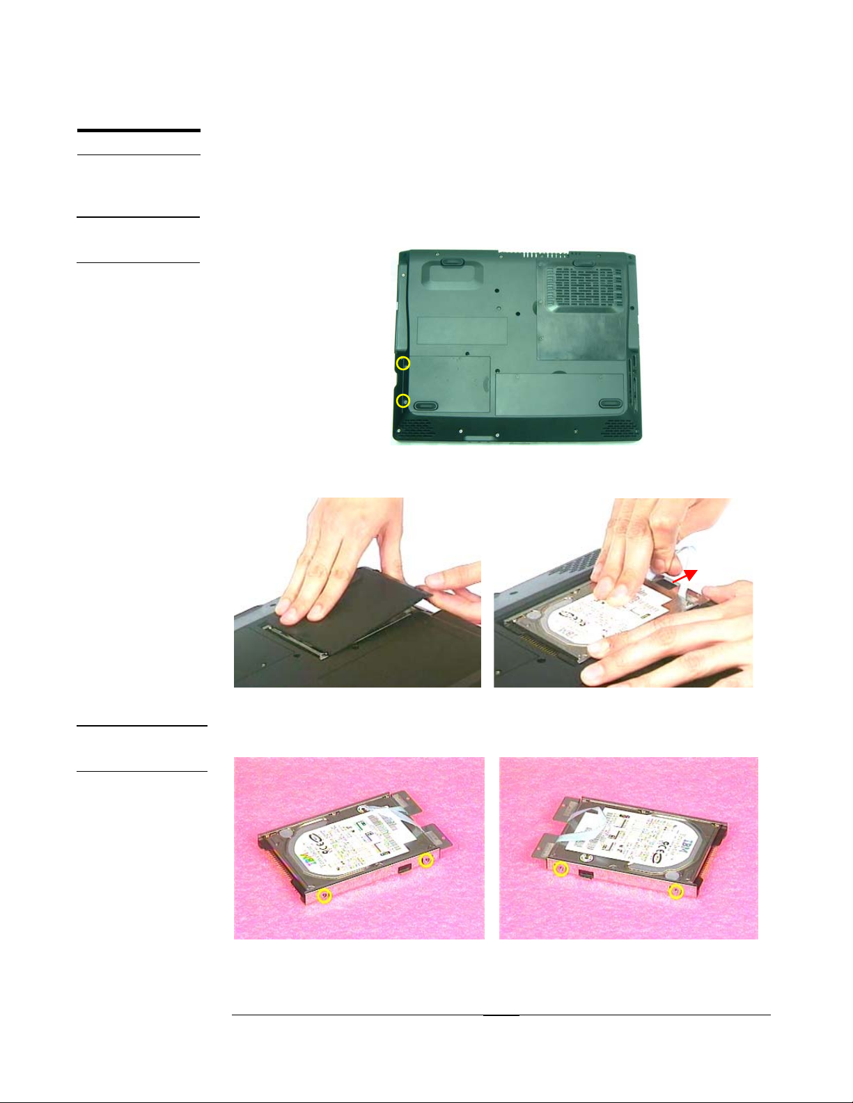
HDD Module
The illustrations below show how to remove the HDD module from the
Portable Desktop.
Removing HDD Module
1. Turn the desktop over and unscrew the 2 screws (M2*4L(K)).
Fig 3.1
2. Remove the HDD door and pull out the HDD module by HDD ribbon.
HDD MODULE
DISASSEMBLY
Fig 3.2 Fig 3.3
Disassembling HDD Module
1. Unscrew the 4 screws (M3*4L(K)) to remove HDD Housing.
Fig 3.4 Fig 3.5
3 - 2
Page 3

DISASSEMBLY PROCEDURE
3. Separate the HDD module from HDD Housing.
SECOND
MEMORY
MODULE
MEMORY
REMOVAL
Fig 3.6
Please do not touch inside of the HDD module.
Memory Module
The D1000 Series Portable Desktop has no onboard memory. There is only
one SO-DIMM socket for installing SO-DIMM RAM. It can upgrade the
memory size up to 512MB module on this socket.
Removing Memory module
1. Unscrew the 2 screws (M2*4L(K)) and then remove the DDR door.
Fig 3.7 Fig 3.8
2. Unlock the socket by pressing the retaining clips outward to pop up the DIMM
and then take it away.
Fig 3.9 Fig 3.10
3 - 3
Page 4
DISASSEMBLY PROCEDURE
CPU MODULE
REMOVAL
CPU
REMOVAL
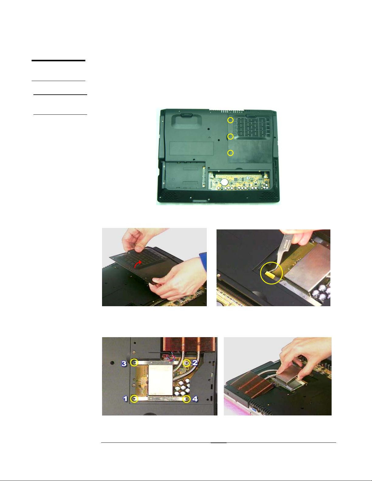
CPU Module
The illustrations below show how to remove the CPU module from the
Portable Desktop.
Removing CPU
1. Unscrew the 3 screws (M2*4L(K)) from thermal door (Fig 3.11).
Fig 3.11
2. Remove the thermal door and use a pair of tweezers to remove the warranty label.
Fig 3.12 Fig 3.13
3. Unscrew the 4 screws (M2.5*8L(BS)) from thermal module (Fig 3.14) and gently
lift the thermal module (Fig 3.15).
Fig 3.14 Fig 3.15
3 - 4
Page 5
DISASSEMBLY PROCEDURE
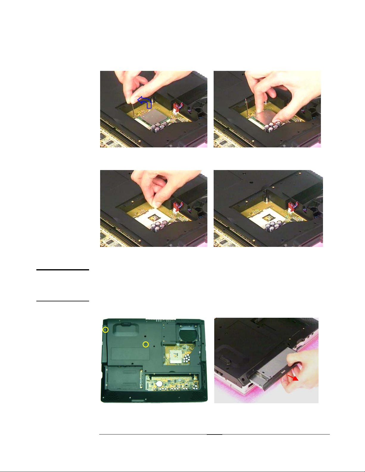
4. Unlock the socket by pressing the lever sideways then lifting it up to a 90~100°
angle (Fig 3.16) and take the CPU away (Fig 3.17).
°
~~°
OPTICAL
DRIVE
MODULE
Fig 3.16 Fig 3.17
5.Push down the socket lever.
Fig 3.18 Fig 3.19
Optical Drive Module
The illustrations below show how to disassemble and remove the Optical
Drive module of the Portable Desktop.
1. Unscrew the two screws as the Fig 3.20(#1, #2) showed and then pulls out the
Optical Drive Module. (Fig 3.21)
11
22
Fig 3.20 Fig 3.21
3 - 5
Page 6
DISASSEMBLY PROCEDURE
KEYBOARD
DISASSEMBLY
KEYBOARD
REMOVAL
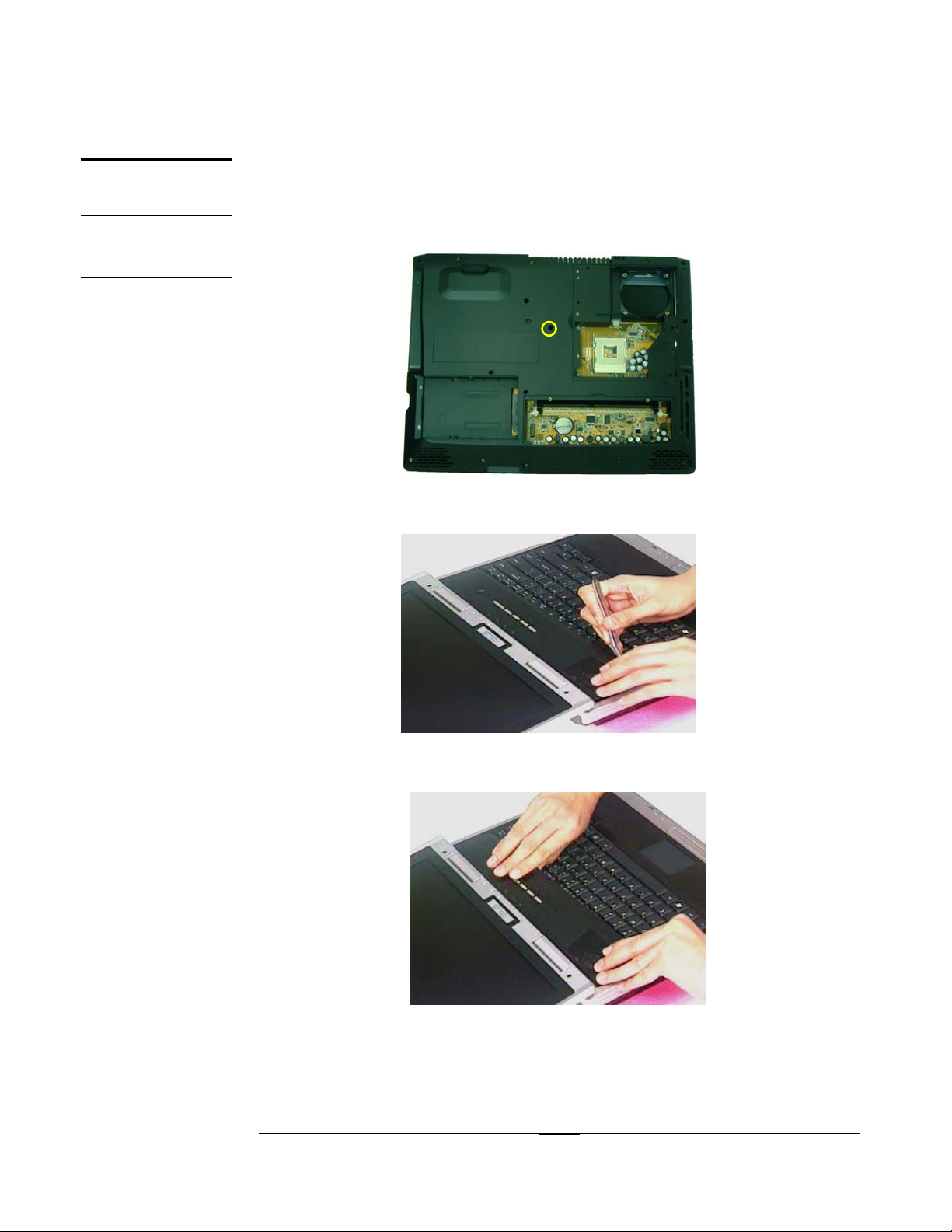
Keyboard Module
The illustrations below show how to remove the keyboard.
Remove Keyboard
1. Remove the 1 screw (M2*7L(K)) on the Bottom Case. (Fig 3.22)
Fig 3.22
2. Lift the keyboard cover with a pair of tweezers. (Fig 3.23)
Fig 3.23
3. Take the keyboard cover away. (Fig 3.24)
Fig 3.24
3 - 6
Page 7

DISASSEMBLY PROCEDURE
4. Pull out the Keyboard and lay the keyboard on the front side. (Fig 3.25)
Fig 3.25
5. Use a flexible connector tool to unlock the cable connector.
Fig 3.26
6. Pull out the keyboard FPC cable with a pair of tweezers and take the keyboard
away.
Fig 3.27 Fig 3.28
3 - 7
Page 8

DISASSEMBLY PROCEDURE
LCD
MODULE
LCD REMOVAL
LCD Module
The illustrations below show how to remove and disassemble the LCD
module. The module contains LCD panel, Inverter board, LCD bracket,
hinge set, LCD front cover and back cover.
*Please do not disassemble the individual parts.
Removing LCD Module
1. Remove the LCD Hinge cover on the right side (Fig 3.29), and another Hinge
cover on the other side. (Fig 3.30)
Fig 3.29 Fig 3.30
2. Unscrew the 2 screws (M2.5*8L(K)) on the bottom case.
Fig 3.31 Fig 3.32
3. Unscrew the 2 screws (M2.5*8L(K)) on the rear side.
Fig 3.33 Fig 3.34
3 - 8
Page 9

DISASSEMBLY PROCEDURE
4. Unscrew the two screws (M2.5*16L(P)) on both hinge sets.
Fig 3.35 Fig 3.36
5. Carefully disconnect the coaxial cable and inverter board cable.
Fig 3.37
6. Turn the LCD module vertical to the desktop. Then carefully lift the LCD module
up to separate the LCD module from the desktop.
Fig 3.38
3 - 9
Page 10

DISASSEMBLY PROCEDURE
LCD
DISASSEMBLY
Disassembling LCD Module
1. Remove the 2 rubber pads and 2 Mylar pad from LCD module.
Fig 3.39
2. Unscrew the 4 screws on the LCD module.
*
*
*
*
Fig 3.40
3. Carefully pry the inside edges of the LCD bezel open on all four edges with your
fingers. Meanwhile, you can push the LCD latch to separate the LCD bezel and
back cover easier. Then, lift the LCD bezel away from the LCD module.
Fig 3.41 Fig 3.42
3 - 10
Page 11

DISASSEMBLY PROCEDURE
4. Carefully pry the Inverter board from the LCD back cover to take out the inverter
board and then disconnect the Inverter board wire (Fig 3.43).
Fig 3.43 Fig 3.44
5. Unscrew the 4 screws (M2.5*6L(K)) on the bottom side, and the 2 screws
(M2*4L(K)) on the top side.
*
*
*
*
Fig 3.45
6.
Separate the bracket from the LCD panel by unscrewing the 4pcs M2*4L(K)
screws and another 4 screws on the other side (Fig 3.46~Fig3.48).
Fig 3.46
3 - 11
Page 12

DISASSEMBLY PROCEDURE
Fig 3.47 Fig 3.48
7. Remove the tape(1)、(2) and conductive tape(3) (Fig 3.49). Disconnect coaxial
cable from LCD panel (Fig 3.50).
33
22
1
1
Fig 3.49 Fig 3.50
8. Remove the hinge set from both sides.
TOP CASE
MODULE
Fig 3.51 Fig 3.52
Top Case Module
The illustrations below show how to disassemble and remove the top case
module of the Portable Desktop. The module contains the Top Case itself,
CPU Fan and TouchPad module.
3 - 12
Page 13
DISASSEMBLY PROCEDURE
TOP CASE
MODULE
REMOVE
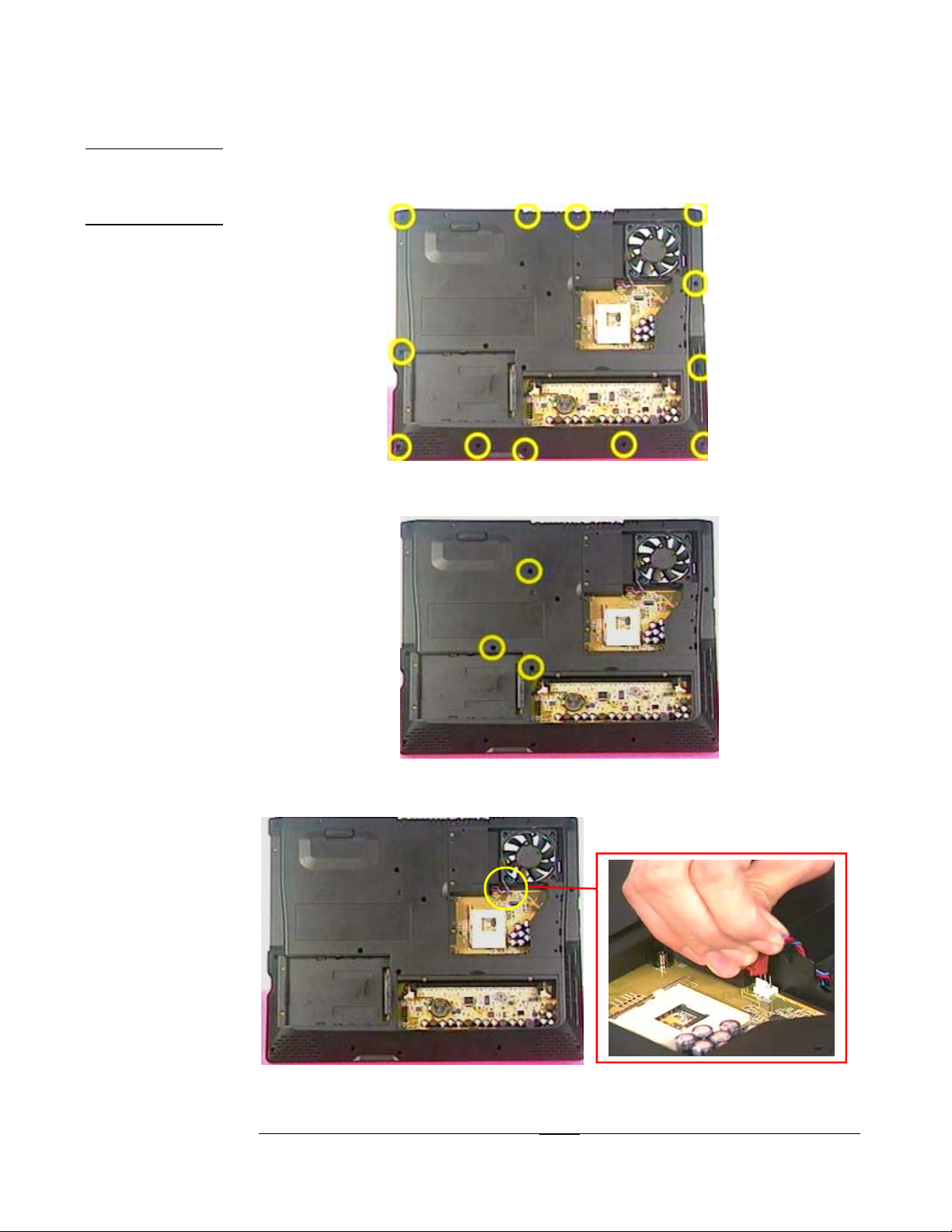
Removing Top Case Module
1. Unscrew the 12 screws (M2*7L(K)) to lossen the motherboard and top case from
bottom case.
11 22 33 44
1122 66
1
1
Unscrew the 3 screws (M2*7L(K)) around HDD.
2.
1
0
9
Fig 3. 53
11
8
55
7
22
33
Fig 3. 54
3. Disconnect the CPU Fan wire. (Fig 3.55)
Fig 3. 55
3 - 13
Page 14

DISASSEMBLY PROCEDURE
4. Turn the desktop over and unscrew the 2 screws (M2*4L(K)). (Fig 3.56)
11 22
Fig 3. 56
5. Unlock the TouchPad cable connector and pull out TouchPad FPC cable.
Fig 3. 57
6. Carefully push in the PCMCIA eject button as #1 showed and then separate the
top case from the bottom case as #2 showed.
2
2
11
Fig 3. 58
3 - 14
Page 15

DISASSEMBLY PROCEDURE
TOUCHPAD
MODULE
REMOVE
Removing TouchPad module
1. Remove the tape (Fig 3.59) and unscrew the 5 screws (M2*4L(K)) to separate the
TouchPad module from top case. (Fig 3.60)
11 22
33 44
5
5
Fig 3. 59 Fig 3. 60
2. Take the TouchPad module away and disconnect FPC cable from TouchPad.
CPU FAN
REMOVAL
MOTHERBOARD
MODULE
Fig 3. 61 Fig 3. 62
Removing CPU Fan
Unscrew the 4 screws (M2.5*8L(BS)) and take the CPU Fan away. (Fig 3.64)
1.
Fig 3. 63 Fig 3. 64
Motherboard Module
The illustrations below show how to disassemble and remove the
motherboard module of the Portable Desktop.
3 - 15
Page 16

SPEARKERS
REMOVAL
DISASSEMBLY PROCEDURE
Removing Speakers Module
1. Remove the tape (1), (2) and disconnect the speaker wire on motherboard.
1
1
2
2
Fig 3.65
2. Remove the speaker sets from the bottom case on both sides.
Fig 3.66 Fig 3.67
Removing Motherboard
1. Disconnect the system fan wire.
2. Unscrew the 3 screws (M2*7L(K)) on motherboard.
3 - 16
Fig 3.68
Page 17

DISASSEMBLY PROCEDURE
MODEM
MODULE
SHIELDING
REMOVAL
Fig 3.69
3. Carefully separate the motherboard from the bottom case.
Fig 3.70
Modem Module
The illustrations below show how to disassemble and remove the modem
module of the Portable Desktop.
Removing Shielding
1. Unscrew the 4 space screws (M2*6(D5)) to take I/O bracket away.
Fig 3.71
3 - 17
Page 18

DISASSEMBLY PROCEDURE
3
2. Press the 5 hooks (#1,#2,#3,#4,#5) as Fig 3.70 showed.
11
22 33
Fig 3.72
44 55
Fig 3.73 Fig 3.74
3. Pull the shielding from the side (#1,#2,#3) as Fig3.73 showed to separate the
shielding from motherboard.
3
22
11
Fig 3.75
3 - 18
Page 19

MODEM
REMOVAL
DISASSEMBLY PROCEDURE
Removing Modem
1. Remove the tape (1) as Fig 3.76 showed and disconnect the modem wire.
1
1
Fig 3.76
2. Unscrew the 2 screws (M2*3L(K)) as Fig3.77 showed and take the modem card
away. (Fig 3.78)
11 2
2
Fig 3.77
3. Disconnect the wire from modem card.
Fig 3.78 Fig 3.79
3 - 19
Page 20

BOTTOM
CASE
MODULE
SYSTEM FAN
REMOVAL
DISASSEMBLY PROCEDURE
Bottom Case Module
The illustrations below show how to disassemble and remove the bottom
case module of the Portable Desktop. The module contains the bottom
case and system fan.
Remove System Fan
1. Unscrew the 3 screws (M2*7(L)).
11
22
33
Fig 3.80
2. Take the system fan away.
Fig 3.81
3 - 20
 Loading...