

Page 1

SERVICE OVERVIEW
T
Service Overview
Carefully read through this chapter for a look at various
components of the desktop and necessary cautions and tools
before performing any service and repairs.
through the overview in this chapter for component overview, cautions and tools to
avoid any unwarranted damages to the desktop’s hardware.
The following chapter includes:
• Overview
• Components
• Precautions
• Appropriate Tools
Chapter
o provide the best service and support for the ASUS D1000 Series Portable
Desktop, we have provided the below information for technicians from
distributors and resellers to perform the complete desktop disassembly and
assembly. But before performing the procedures, please be sure to read
2 - 1
Page 2
SERVICE OVERVIEW
D1000 Series Portable Desktop Overview
and Components
The ASUS D1000 Series Portable Desktop is a product combining the power of
Intel® Pentium 4 CPU with FC- PGA2 desktop system. In this section, an overview
for the D1000 Series, along with its components, will be presented.
OVERVIEW
D1000 Series Portable Desktop Overview
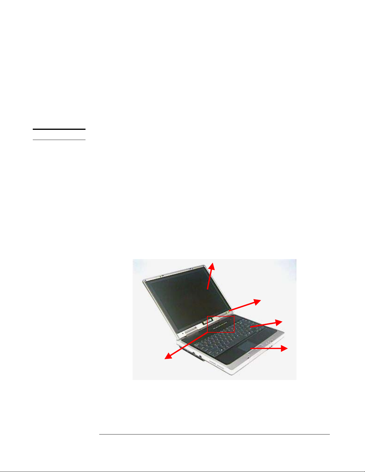
The illustrations below show the desktop’s overview from left front view, right front
view, rear view and bottom view. Most of the parts will be discussed in this manual.
1. LCD display panel
2. LCD front cover
3. Keyboard
4. Touch Pad Module
5. Instant Key
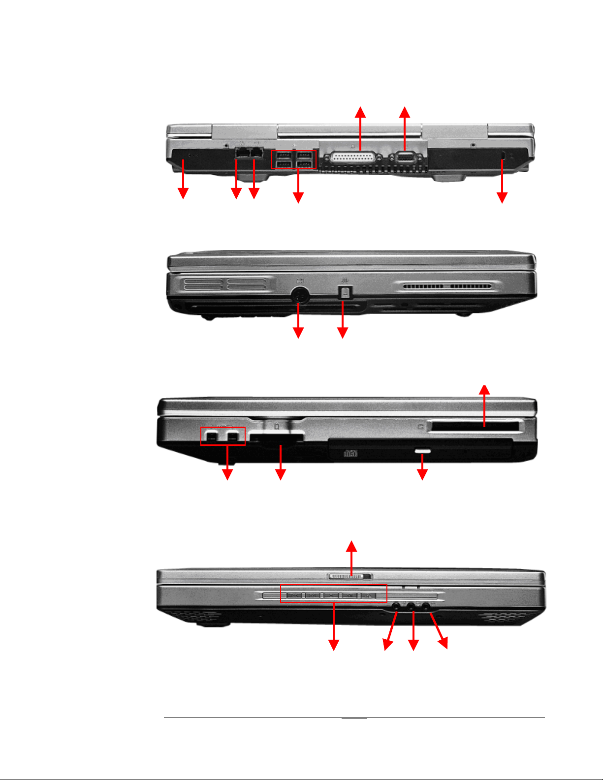
6. Reset Button
7. LAN Port
8. Modem Port
9. USB Ports
10. Parallel Port
11. External Monitor
Port
12. Kensington Lock
13. DC Power Input Jack
14. SPDIF Jack
15. IEEE 1394 Port
16. Multimedia Card
Reader Socket
17. PCMCIA Socket
18. Optical Drive
19. Multimedia DJ Panel
1
20. LCD Latch
21. Microphone Jack
22. Line In Jack
23. Line Out Jack
24. HDD Compartment
25. CPU FAN
26. CPU Compartment
27. Memory
Compartment
Fig 2.1
2 - 2
4
Page 3
SERVICE OVERVIEW
6 7 8 9 12
Fig 2.2
13 14
Fig 2.3
15 16 17
Fig 2.4
19 21 22 23
Fig 2.5
2 - 3
Page 4
SERVICE OVERVIEW
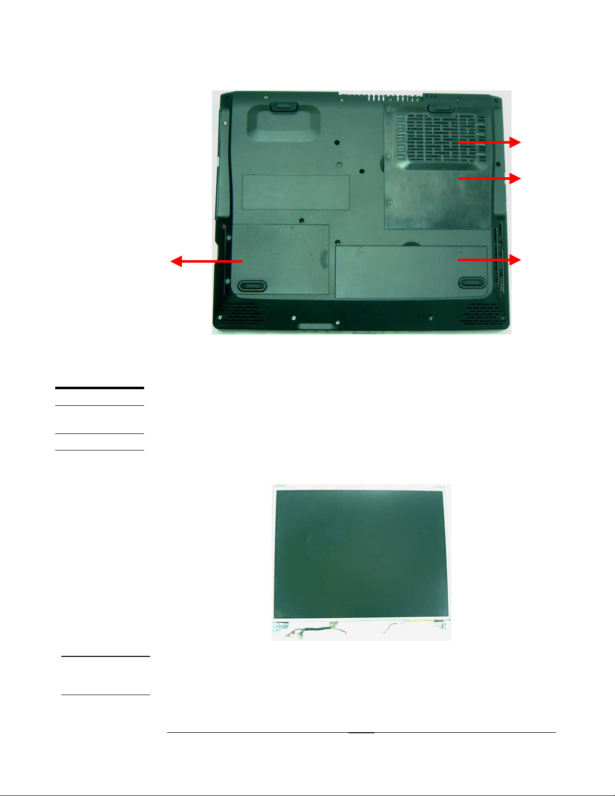
25
26
24 27
COMPONENTS
LCD
Fig 2.6
Components
The illustrations below show the components of the D1000 Series Portable Desktop.
LCD Panel*
The illustration below shows the LCD display panel. The D1000 Series Portable
Desktop comes with 14.1’’ or 15” TFT.
Fig 2.7
INVERTER
Inverter Board Module
The illustration below shows the inverter board, which is hidden underneath the lower
MODULE
edge of the LCD front bezel.
2 - 4
Page 5

SERVICE OVERVIEW
LCD
BRACKETS
HINGE
COVERS
Fig 2.8
LCD Brackets
The illustration below shows the brackets that support the LCD module.
Fig 2.9
Hinge Covers
The illustration below shows the hinge covers that conceal the LCD hinges.
LCD CASE
Fig 2.10
LCD Case
The illustration below shows the LCD front bezel and back cover.
Fig 2.11 Fig 2.12
2 - 5
Page 6

SERVICE OVERVIEW
KEYBOARD
TOUCHPAD
Keyboard
on below shows the keyboard plate. The illustrati
TouchPad Module
The illustration below
Fig 2.13
shows the TouchPad module.
TOP CASE
MODULE
Fig 2.14
Top Case Module
The illustration below
shows the top case of the portable desktop.
Fig 2.15
2 - 6
Page 7

SERVICE OVERVIEW
HDD
HDD HOUSING
Hard Disk Drive
The illustration below shows the 2.5” industry-standard HDD with 9.5mm height.
Fig 2.16 Fig 2.17
HDD Shielding Plate
The illustration below shows the HDD Housing that is placed over the HDD.
CPU
CPU HEAT
SINK
Fig 2.18
FC-PGA2 CPU Module
The illustration below shows the Intel FC-PGA2 CPU Module, top and bottom views.
Fig 2. 19 Fig 2.20
CPU Thermal Module
The illustration below shows the thermal module for the CPU.
2 - 7
Page 8

CPU FAN
SERVICE OVERVIEW
Fig 2.21
CPU Fan
The illustration below shows the fan for the CPU.
SYSTEM FAN
Fig 2.22 Fig 2.23
System Fan
The illustration below shows the fan for the system. It’s located on the bottom case.
Fig 2.24 Fig 2.25
2 - 8
Page 9

SERVICE OVERVIEW
MODEM
BOARD
RTC BATTERY
MEMORY
Modem Board
The illustration below shows the Modem board.
Fig 2.26
RTC Battery
The illustration below shows the RTC battery that keeps the internal clock running.
Fig 2.27
Memory Module
The illustration below shows the industry-standard 184pin DDR SDRAM module for
the portable desktop.
MOTHER-
BOARD
MODULE
Fig 2.28
Motherboard Module
The illustration below shows the motherboard module of the portable desktop.
Fig 2.29 Fig 2.30
2 - 9
Page 10

SERVICE OVERVIEW
BOTTOM CASE
MODULE
KEYBOARD
COVER
MODULE
Bottom Case Module
The illustration below shows the bottom module of the portable desktop.
Fig 2.31 Fig 2.32
Keyboard Cover Module
The illustration below shows the keyboard cover of the portable desktop.
SPEAKER
SET
Fig 2.33
Speaker Set
The illustration below shows the Speaker set of the portable desktop.
Fig 2.34
2 - 10
Page 11

SERVICE OVERVIEW
Service Overview
Please pay special attention to the cautions below to prevent any damages to the
portable desktop and also please be sure to select the appropriate tools described in
this section to perform any services desired.
CAUTIONS
Precautions
Before you perform any service and/or repair on the portable desktop, please follow
the steps below first.
1. Be sure that the portable desktop is powered down.
2. Disconnect the AC plug from the left side of the desktop.
Fig 2.35
3. Remove all rings, watches and any other metal objects from your hands.
4. Always wear a ground strap on your hand to protect the desktop from static
discharge.
2 - 11
Page 12

SERVICE OVERVIEW
TOOLS
CROSS
SCREW-
DRIVER
TWEEZERS
SPACER
SCREW-
DRIVER
PLIERS
Appropriate Tools
The illustrations below show the appropriate tools that should be used for the
desktop’s service and repair.
Phillips-head Screwdriver
Use a Phillips-head screwdriver to fasten/remove the K- or B-typed screws.
Tweezers
Use a pair of tweezers to remove/insert flexible cables.
Spacer Screwdriver
Use a spacer screwdriver to fasten/remove spacer screws or hex screws.
Pliers
Use a pair of pliers to handle regular cables.
INSERTION
AND
EXTRACTION
TOOL FOR
FPC
CONNECTOR
Insertion and extraction tool for FPC connector
Use insertion and extraction tool for FPC connector to handle locking and unlocking
of FPC connectors.
2 - 12
 Loading...