

Page 1

UPGRADE & REPLACEMENT
Upgrade & Replacement
Follow the individual procedures in this chapter to perform the
Portable Desktop’s upgrade and replacement of various major
components.
sus D1000 Series Portable Desktop is an all-in-one product, which means
there are more options for you to upgrade to. The key upgradeable and
A
In order to avoid redundancy, please refer to chapters 3 and 4 of this manual for
repeated and reused disassembly and assembly procedures, such as keyboard &
thermal module replacement, which is used by several different procedures in this
chapter.
safeguard the Portable Desktop against any potential damages.
components not covered in this chapter, which you need to replace, please refer to
Chapters 3 and 4 for detailed disassembly and assembly and perform necessary
procedures accordingly.
This chapter includes the following items:
• HDD Upgrade & Replacement
• Memory Upgrade & Replacement
• CPU Upgrade & Replacement
• Optical Drive Module Replacement
replaceable items include HDD, Memory, CPU and Optical Drive Module.
Be sure to follow the safety instructions described in Chapter 2 to
Chapter
5
For any other
5 - 1
Page 2
UPGRADE & REPLACEMENT
HDD
MEMORY
MEMORY
MEDULE
REMOVAL
HDD Upgrade & Replacement
The D1000 Series Portable Desktop uses an industry-standard 2½” HDD with IDE
interface. You can replace the HDD to any capacity of your choice within our
approval and prior test.
First, remove AC-power.
1. Remove HDD module and disassemble the HDD Module (p.3-2).
2. Replace HDD.
3. Place HDD housing on a new HDD and assemble the module (p.4-19)
4. Install the new HDD module (p.4-20).
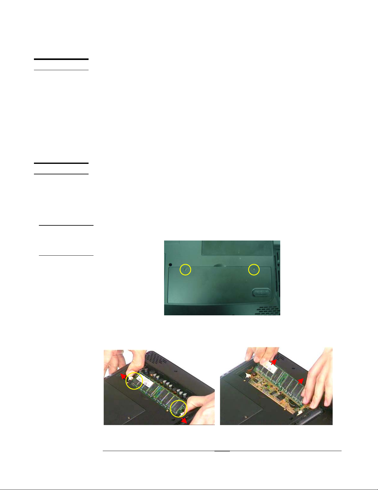
Memory Upgrade & Replacement
The D1000 Series Portable Desktop has no onboard memory. There is only one SODIMM socket for installing SO-DIMM RAM. It can upgrade the memory size up to
512MB module on this socket.
First, remove AC-power.
Upgrading Memory Module.
1. Unscrew the 2 screws (M2*4L(K)) and then remove the DDR door.
Fig 5.1
2. Unlock the socket by pressing the retaining clips outward to pop up the DIMM
(Fig 5.2) and then take it away. (Fig 5.3).
Fig 5.2 Fig5.3
5 - 2
Page 3
MEMORY
INSTALL
UPGRADE & REPLACEMENT
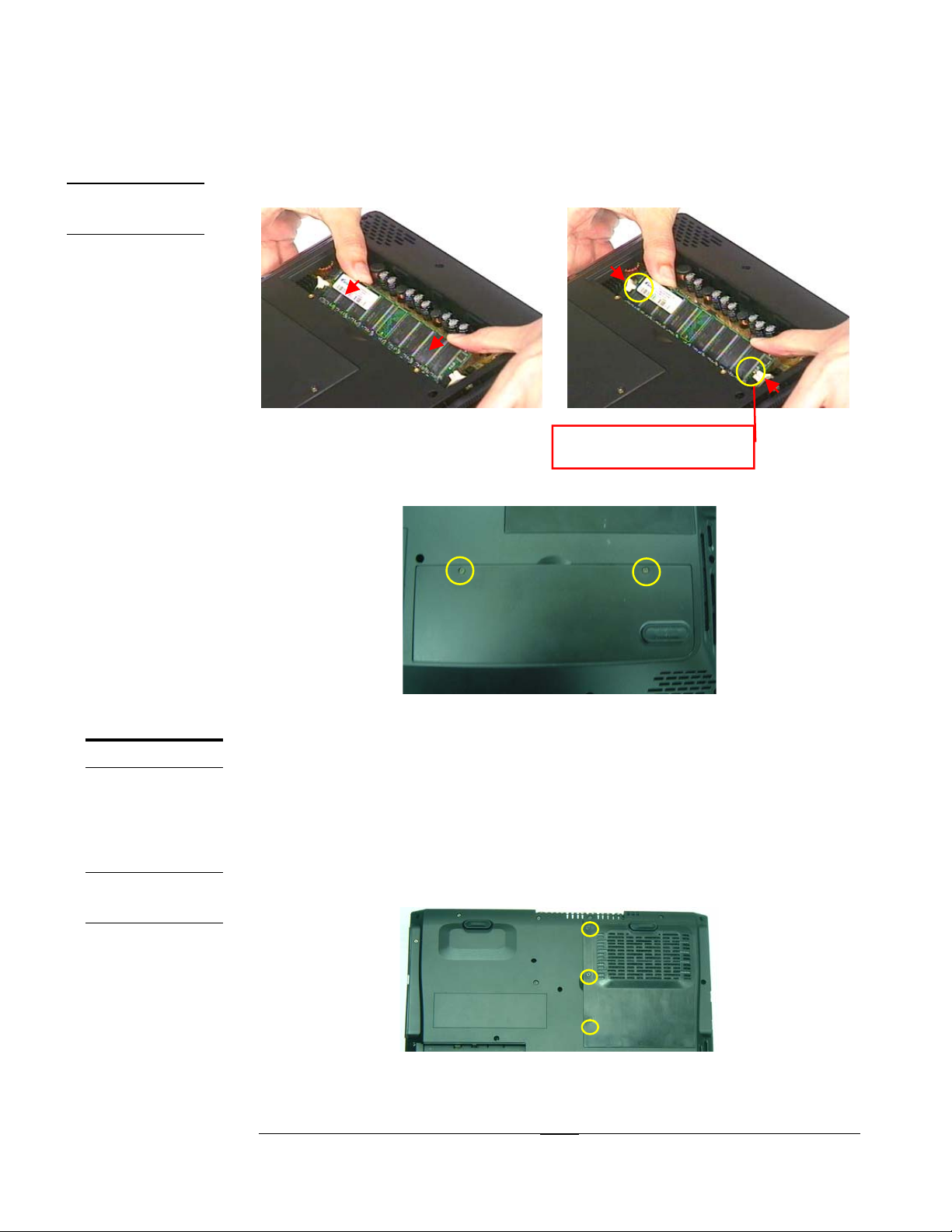
Memory Install
1. Insert a new DIMM module into the socket until the retaining clips snap back in
place.
CPU
CPU
REMOVAL
Fig 5.4 Fig 5.5
Lock by retaining clips
2. Take a DDR door, install it on chassis.
3. Mount 2pcs of M2*4L(K) screws to fix DDR Door.
Fig 5.6
CPU Upgrade
The D1000 Series Portable Desktop comes standard with a Intel®’ s mPGA2 Socket
on the motherboard, which means it can support all FC-PGA2 CPUs up to 2.4 GHz.
First, remove AC-power.
Removing CPU
1. Unscrew the 3 screws (M2*4L(K)) screws from thermal door .
Fig 5.7
5 - 3
Page 4

UPGRADE & REPLACEMENT
2. Remove the thermal door and use a pair of tweezers to remove the warranty label.
Fig 5.8 Fig 5.9
Unscrew the 4 screws (M2.5*8L(BS)) from thermal module (Fig 5.11) and gently
3.
lift the thermal module (Fig 5.12).
Fig 5.11 Fig 5.12
4. Unlock the socket by pressing the lever sideways then lifting it up to a 90~100°
angle (Fig 5.13) and take the CPU away (Fig 5.14).
9900~~110000°°
Fig 5.13 Fig 5.14
CPU INSTALL
Install CPU
5. Make sure the CPU pin1 matches the base of the socket lever. (Fig 5.15)
1. Install a new CPU onto the socket. (Fig 5.16)
5 - 4
Page 5

UPGRADE & REPLACEMENT
Fig 5.15 Fig 5.16
2. Push down the lever to secure the CPU.
Fig 5.17 Fig 5.18
3. Clean the thermal module with a flat-bar like tool.
Fig 5.19 Fig 5.20
4. Peel off the plastic pad, sticks it on thermal module.
5. Press the THERAML PAD to make sure it sticks on the thermal module exactly.
Fig 5.21 Fig 5.22
5 - 5
Page 6

UPGRADE & REPLACEMENT
6. Peel off another plastic pad and install thermal module into chassis.
Fig 5.23 Fig 5.24
7. By sequencely, mount 4pcs of (M2.5*8L(BS)) screws to fix thermal module.
Fig 5.25
8. Stick the warranty label.
Fig 5.26.
9. Take a thermal door and install it on chassis.
10. Mount 3pcs of (M2*4L(K)) screws to fix thermal door.
Fig 5.27
5 - 6
Page 7

UPGRADE & REPLACEMENT
OPTICAL
DRIVE
MODULE
Optical Drive Module Replacement
First, remove AC-power.
Remove Optical Drive Module
1. Turn the desktop over.
2. Unscrew the 2 screws as the Fig 5.28(#1, #2) showed and then pull out the
Optical Drive Module. (Fig 5.29)
11
22
Fig 5.28 Fig 5.29
Install Optical Drive Module
1. Place the new module into the socket until it snaps the place. (Fig 5.30)
2. Then secure the 2 screws to fix the module with the Portable Desktop. (Fig 5.31)
11
22
Fig 5.30 Fig 5.31
5 - 7
 Loading...