

Page 1

ASSEMBLY PROCEDURE
A
Assembly Procedure
Please follow the information provided in this section to
perform the complete assembly procedure of the Portable
Desktop. Be sure to use proper tools described before.
individual modules will be provided for your service needs.
Chapter
Chapter
4
fter you have completed the previous chapter of complete disassembly, please
follow this chapter to assemble the Portable Desktop back together. This
chapter describes the procedures of the complete Portable Desktop assembly.
In addition, in between procedures, the detailed assembly procedure of
The assembly procedure consists of the following steps:
• Bottom Case Module
• Modem Module
• Motherboard Module
• Top Case Module
• LCD Module
• Keyboard Module
• Optical Drive Module
• CPU Module
• Memory Module
• HDD Module
4 - 1
Page 2
ASSEMBLY PROCEDURE
BOTTOM CASE
MODULE
SYSTEM FAN
INSTALL
Bottom Case Module
The illustrations below show how to assemble and install the bottom case
module of the Portable Desktop. The module contains the bottom case itself
and system fan.
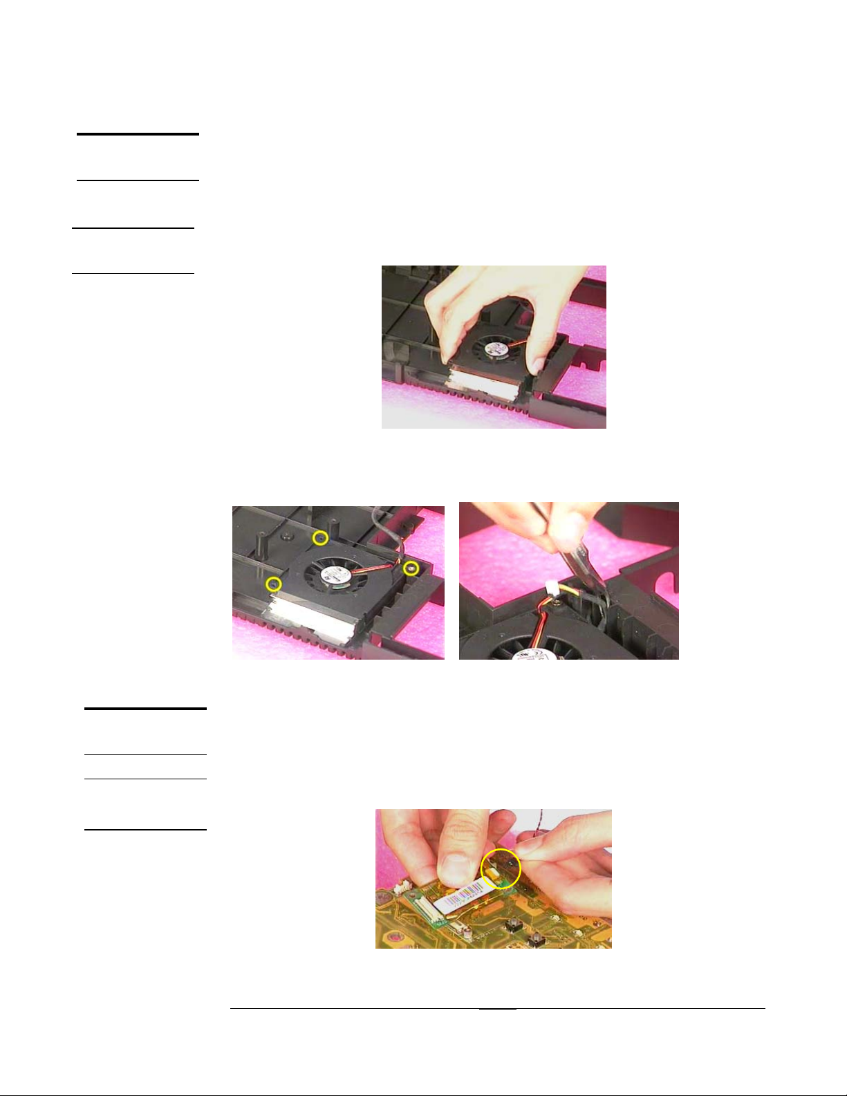
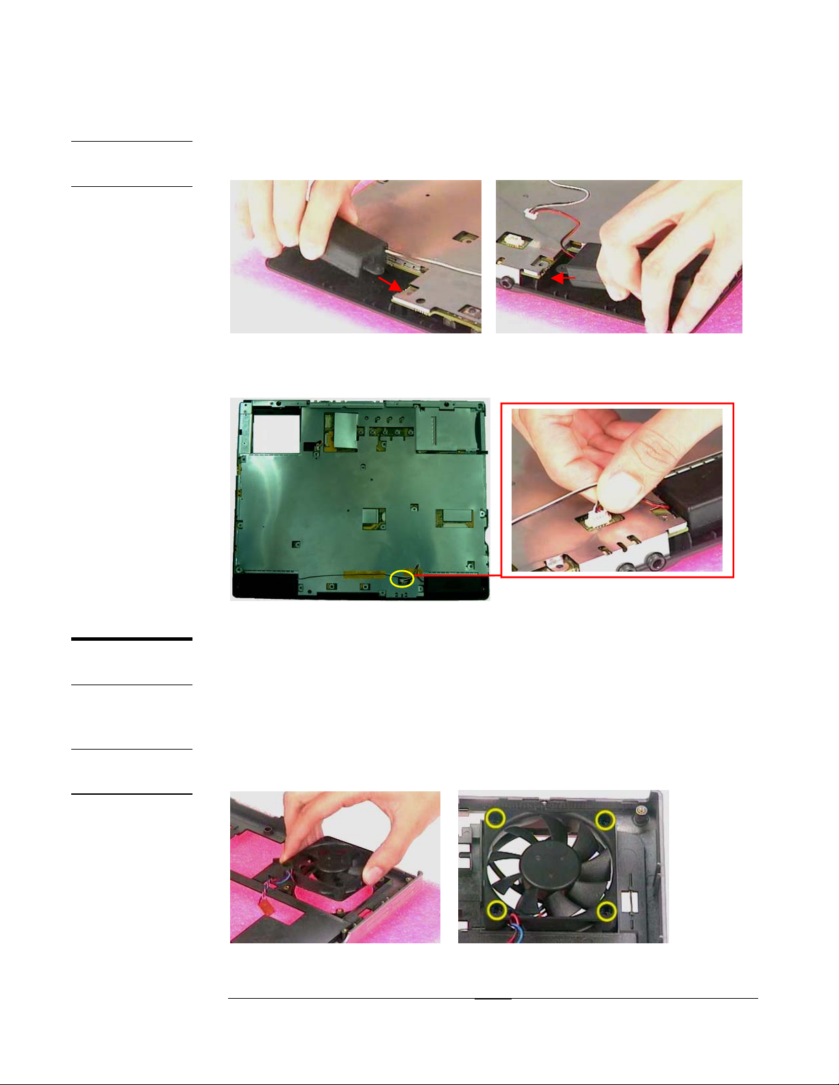
Installing System Fan
1. Take a System Fan and place it on the bottom case.
Fig 4.1
2.
Secure the 3 pcs of (M2*7(L)) screws to fix System Fan (torque : 2.0kgf-cm±10%).
3.
Please be sure the system fan wire routed properly. (Fig 4.3)
MODEM
MODULE
MODEM
INSTALL
11
33 22
Fig 4.2 Fig 4.3
Modem Module
The illustrations below show how to assemble and install the modem
module of the Portable Desktop.
Installing Modem
1. Take a modem wire and connect it on modem card.
Fig 4.4
4 - 2
Page 3
ASSEMBLY PROCEDURE
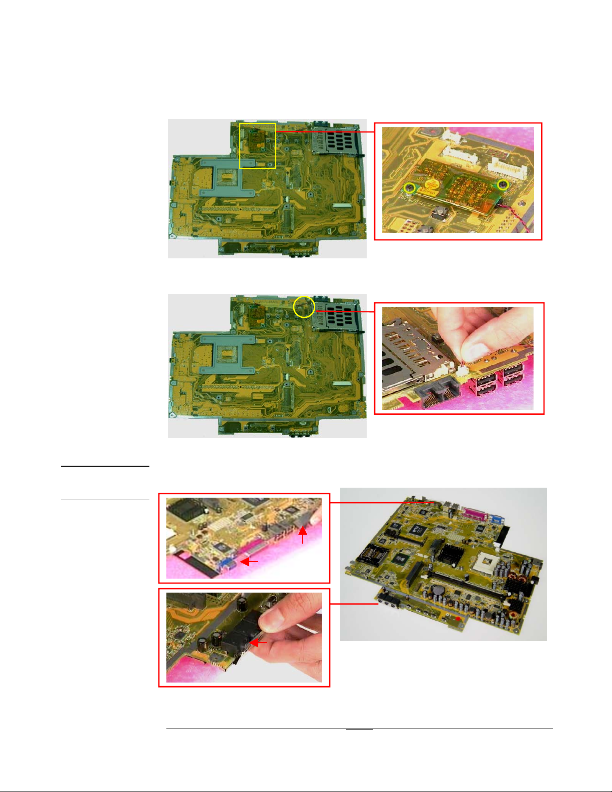
2. Install the modem on motherboard and mount 2pcs of M2*3L(K) screws to fix it
(torque : 2.0kgf-cm±10%).
SHIELDING
ASSEMBLY
11 2
2
Fig 4.5
3. Connect the modem wire on motherboard and stick the tape (1) to fix the cable.
1
1
Fig 4.6
Assembling Shielding
1. Push the shielding from the side (#1,#2,#3) as Fig 4.7 showed.
11
22
2.
33
Fig 4.7
4 - 3
Page 4
ASSEMBLY PROCEDURE
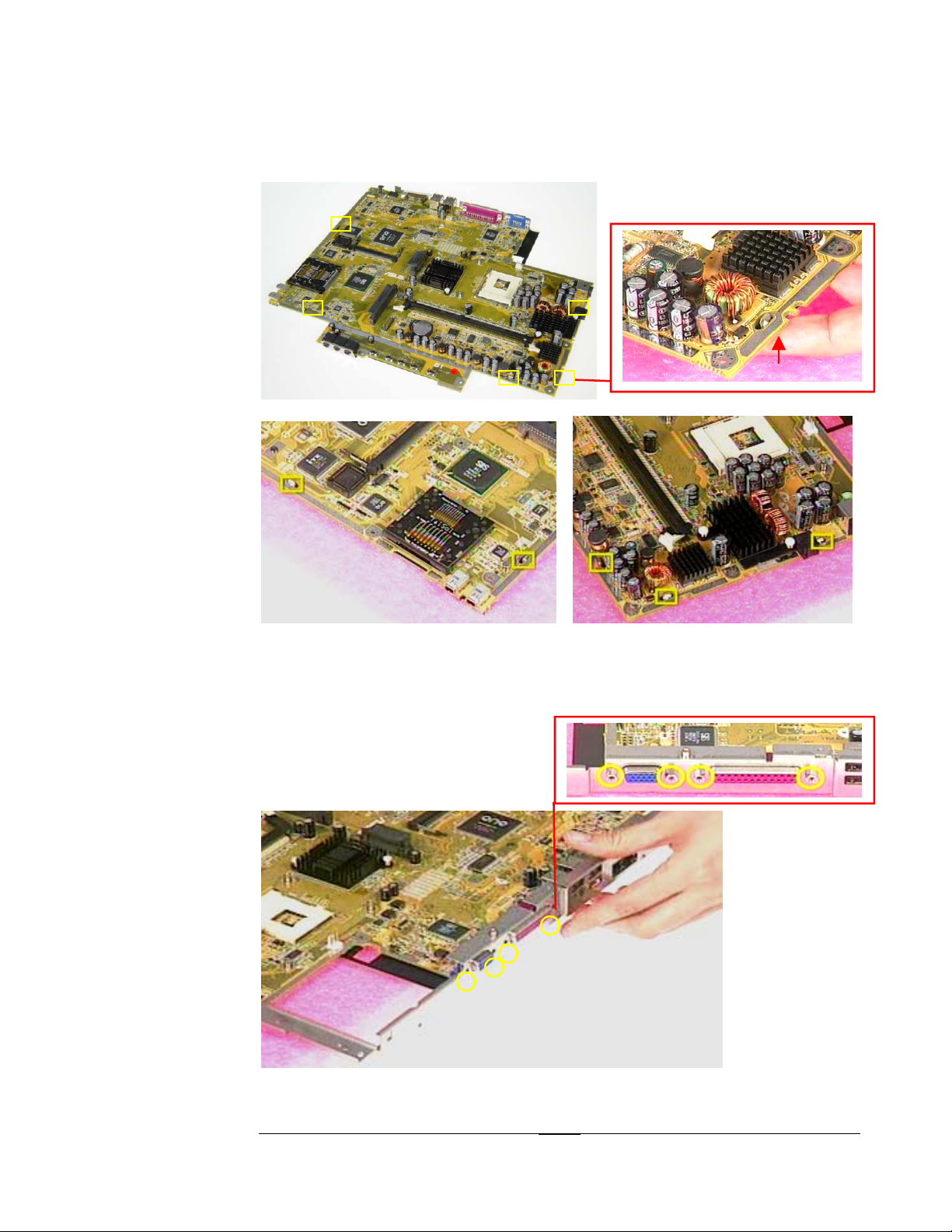
3. Press the 5 hooks (#1,#2,#3,#4,#5) as Fig 4.8 showed to combine the shielding
and motherboard.
11
22 33
Fig 4.8
44 55
Fig 4.9 Fig 4.10
4. Place the I/O bracket on motherboard and secure the 4 space screws (M2*6(D5))
to fix I/O bracket (torque : 3.5kgf-cm±0.3).
Fig 4.11
4 - 4
Page 5
ASSEMBLY PROCEDURE
MOTHERBOARD
MODULE
SPEARKERS
REMOVAL
Motherboard Module
The illustrations below show how to assemble and install the motherboard
module of the Portable Desktop.
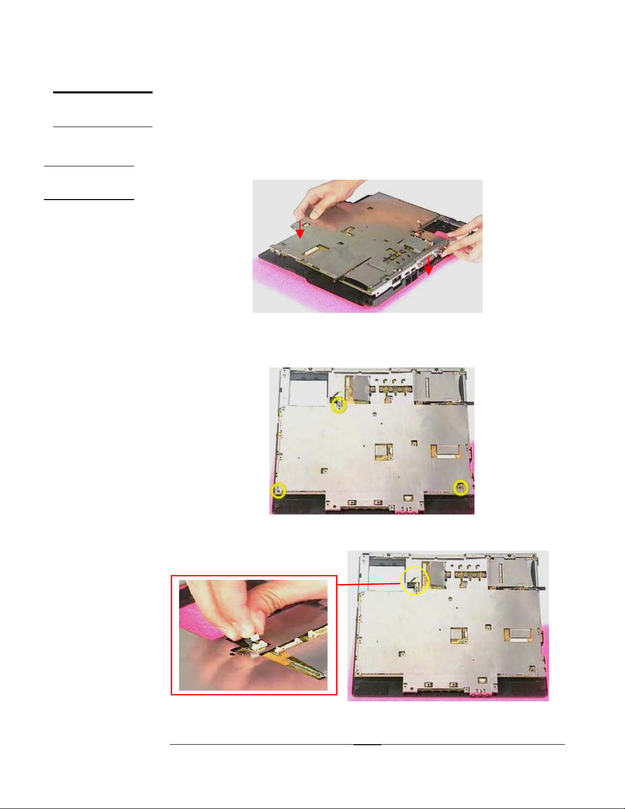
Installing Motherboard Module
1. Lay the motherboard module down on the bottom case.
Fig 4.12
2. Mount the 3 screws (M2*7L(K)) to fix motherboard module on bottom case
(torque : 2.0kgf-cm±10%).
Fig 4.13
3. Connect the system fan wire on motherboard.
Fig 4.14
4 - 5
Page 6
SPEARKERS
INSTALL
ASSEMBLY PROCEDURE
Installing Speakers Module
1. Install speaker sets about 30 degrees between motherboard and bottom case
on both sides.
TOP CASE
MODULE
CPU FAN
INSTALL
Fig 4.15 Fig 4.16
2. Connect the speaker wire on motherboard
3. Add 2pcs of tape to fix the speaker wire on shielding.
1
1
2
2
Fig 4.17
Top Case Module
The illustrations below show how to assemble and install the top case
module of the Portable Desktop. The module contains the Top Case itself,
CPU Fan and TouchPad module.
Removing CPU Fan
1.
Place the CPU Fan on the top case and mount 4 screws (M2.5*8L(BS)) to fix it
(torque : 2.0kgf-cm±10%).
Fig 4.18 Fig 4.19
4 - 6
Page 7

TOUCH PAD
MODULE
ASSEMBLY
ASSEMBLY PROCEDURE
Assembling TouchPad Module
1. Connect the FPC cable into TouchPad with a pair of tweezers.
TOP CASE
MODULE
ASSEMBLY
Fig 4.20 Fig 4.21
1. Secure 5 screws (M2*4(L)) to fix the TouchPad module on top case (torque :
2.0kgf-cm±10%). (Fig 4.22)
2. Use tape to fix the cable. (Fig 4.23)
11 22
33 44
5
5
Fig 4.22 Fig 4.23
Assembling Top Case Module
1. Carefully push in the PCMCIA eject button for easier installation of top case as #1
showed.
2. Assemble the top case with bottom case as #2 showed.
2
2
Fig 4.24
4 - 7
11
Page 8

ASSEMBLY PROCEDURE
3. Connect the TouchPad FPC cable on motherboard.
Fig 4.25
4. Secure the 2 screws (M2*4L(K)) (torque : 2.0kgf-cm±10%).
Fig 4.26
5. Connect the CPU Fan wire. (Fig 4.27)
Fig 4.27
6.
Mount the 3pcs of (M2*7L(K)) screws around HDD (torque : 2.0kgf-cm±10%)
(Fig 4.28).
7. Mount the 12pcs of (M2*7L(K)) screws to fix the top case and bottom case
(torque : 2.0kgf-cm±10%). (Fig 4.29)
4 - 8
Page 9

ASSEMBLY PROCEDURE
22
33
11
LCD
MODULE
ASSEMBLY
Fig 4.28
11 22 33 44
1122 66
1
1
1
0
9
Fig 4.29
8
55
7
LCD Module
The illustrations below show how to assemble and install the LCD module
into the Portable Desktop. The module contains LCD panel, Inverter board,
LCD bracket, hinge set, LCD front cover and back cover.
1. Place the Hinge_ R on the left side, and the Hinge_L on the other side.
Fig 4.30 Fig 4.31
4 - 9
Page 10
ASSEMBLY PROCEDURE
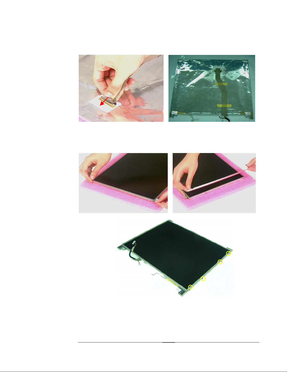
2. Connect coaxial cable into LCD panel (Fig 4.32) and stick 2pcs tape and
conductive tape to fix the coaxial cable on LCD. (Fig 4.33)
11
22
3
3
Fig 4.32 Fig 4.33
3. Install the bracket on LCD panel and mount 4pcs of M2*4L(K) screws to fix it
(torque : 2.0kgf-cm±0.2), and repeat the same procedure on other side. (Fig
3.34~Fig3.36)
Fig 4.34 Fig 4.35
Fig 4.36
4. Install LCD panel into LCD back cover.
5. Mount the 4 screws (M2.5*6L(K)) on the bottom side (torque :3.0~3.2kgf-cm),
and the 2 screws (M2*4L(K)) on the top side (torque : 2.0kgf-cm±10%).
4 - 10
Page 11

ASSEMBLY PROCEDURE
*
*
*
*
Fig 4.37
6. Connect LCD cable and inverter board wire on inverter board, and then install
inverter board into LCD cover. (Fig 4.38).
Fig 4.38 Fig 4.39
7. Assemble the LCD bezel and LCD back cover exactly.
Fig 4.40
8. Mount 4pcs of screws to fix LCD bezel. (Fig 4.41)
9. Stick 2 rubber pads and 2 Mylar pad on these four screw holes. (Fig 4.42)
4 - 11
Page 12

ASSEMBLY PROCEDURE
*
*
*
*
LCD INSTALL
Fig 4.41
Fig 4.42
Installing LCD Module
1. Place the LCD module straight down and make sure the LCD hinge feet are
properly aligned.
Fig 4.43
2. Connect the coaxial cable and inverter board cable on motherboard. (Fig 4.44)
3. Route the coaxial cable under the chassis. (Fig 4.46)
4 - 12
Page 13

ASSEMBLY PROCEDURE
Fig 4.44
Fig 4.45 Fig 4.46
4. Secure the two screws (M2.5*16L(P)) on both hinge sets (torque : 3.5kgf-cm±0.3).
Fig 4.47 Fig 4.48
5. Secure the 4 screws (M2.5*8L(K)) on the rear side and bottom side (torque :
3.5kgf-cm±0.3).
Fig 4.49 Fig 4.50
4 - 13
Page 14

ASSEMBLY PROCEDURE
KEYBOARD
MODULE
ASSEMBLY
Fig 4.51 Fig 4.52
6. Slide in LCD Hinge covers on both sides.
Fig 4.53 Fig 4.54
Keyboard Module
The illustrations below show how to assemble and install the Keyboard
Module
Installing Keyboard
1. Open the K/B connector latch on M/B.Take a K/B module, insert the K/B FPC
2. Insert the five K/B ribs into chassis and then place the K/B on chassis. (Fig 4.57)
into the connector to the very bottom and then lock the latch. (Fig 4.56)
Fig 4.55 Fig 4.56
4 - 14
Page 15

ASSEMBLY PROCEDURE
Fig 4.57
3. Install the keyboard cover into chassis. Then press the keyboard cover to
lock it.
Fig 4.58
4. Mount the 1 screws (M2*7L(K)) to fix the keyboard (torque : 2.0kgf-cm±10%).
4 - 15
Fig 4.59
Page 16

OPTICAL DRIVE
MODULE
INSTALLATION
ASSEMBLY PROCEDURE
Optical Drive Module
The illustrations below show how to assemble and install the Optical Drive
module of the Portable Desktop.
1. Insert the optical drive module into chassis to make sure having a fully
contact with CD-FPC.
2. Secure the 2 screws (M2*4L(K)) to fix the module (torque : 2.0kgf-cm±
10%).
11
22
CPU INSTALL
CPU INSTALL
Fig 4.60 Fig 4.61
CPU Module Assembly
The illustration below shows how to install CPU Fan, CPU and the heat sink plate.
CPU Install
1. Unlock the socket by pressing the lever sideways then lift it up to a 90°~100°.
~
°
~
°
Fig 4.62 Fig 4.63
2. Make sure the pin1 matches the base of the socket lever.
Fig 4.64 Fig 4.65
4 - 16
Page 17

ASSEMBLY PROCEDURE
3. Push down the lever to secure the CPU.
Fig 4.66 Fig 4.67
4. Clean the thermal module with a flat-bar like tool.
Fig 4.68 Fig 4.69
5. Peel off the plastic pad, sticks it on thermal module.
6. Press the THERAML PAD to make sure it sticks on the thermal module exactly.
Fig 4.70 Fig 4.71
7. Peel off another plastic pad and install thermal module into chassis.
Fig 4.72 Fig 4.73
4 - 17
Page 18

ASSEMBLY PROCEDURE
8. By sequencely, mount 4pcs of (M2.5*8L(BS)) screws to fix thermal module
(torque : 2.0kgf-cm±10%).
Fig 4.74
9. Stick the warranty label.
Fig 4.75
10. Take a thermal door. After checking no cosmetic problem, then install it on
chassis.
11. Mount 3pcs of (M2*4L(K)) screws to fix thermal door (torque : 2.0kgf-cm±10%).
Fig 4.76
4 - 18
Page 19

ASSEMBLY PROCEDURE
MEMORY
MODULE
INSTALL
MEMORY
INSTALL
Memory Module
The illustrations below show how to install the Memory Module.
Memory Install
1. Insert a DIMM module into the socket until the retaining clips snap back in place.
Fig 4.77 Fig 4.78
2. Take a DDR door, install it on chassis.
3. Mount 2pcs of M2*4L(K) screws to fix DDR Door (torque : 2.0kgf-cm±10%).
Lock by retaining clips
HDD
MODULE
HDD MODULE
INSTALL
Fig 4.79
HDD Module
The illustrations below show how to assemble and install the HDD module
of the Portable Desktop.
Installing HDD module
1. Place the HDD drive onto the HDD Housing.
2. Mount 4pcs of M3*4L(K) screws to fix HDD module(torque : 2.0kgf-cm±10%).
4 - 19
Page 20

ASSEMBLY PROCEDURE
Fig 4.80
Fig 4.81 Fig 4.82
3. Pull the HDD close with the HDD connector by HDD ribbon.
Fig 4.83
4. Install HDD DOOR on chassis.
4. Mount 2pcs of M2*4L(K) screw to fix the HDD door (torque : 2.0kgf-cm±10%).
2
2
Fig 4.84
4 - 20
 Loading...