

Page 1
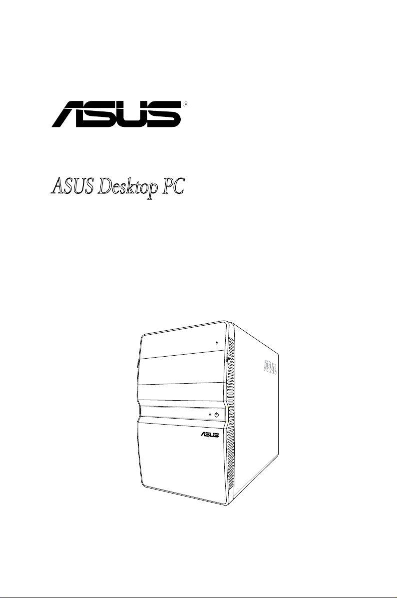
CT5430
ASUS Desktop PC
Page 2

ii
Copyright © 2007 ASUSTeK COMPUTER INC. All Rights Reserved.
No part of this manual, including the products and software described in it, may be reproduced,
transmitted, transcribed, stored in a retrieval system, or translated into any language in any form or by any
means, except documentation kept by the purchaser for backup purposes, without the express written
permission of ASUSTeK COMPUTER INC. (“ASUS”).
Product warranty or service will not be extended if: (1) the product is repaired, modied or altered, unless
such repair, modication of alteration is authorized in writing by ASUS; or (2) the serial number of the
product is defaced or missing.
ASUS PROVIDES THIS MANUAL “AS IS” WITHOUT WARRANTY OF ANY KIND, EITHER EXPRESS
OR IMPLIED, INCLUDING BUT NOT LIMITED TO THE IMPLIED WARRANTIES OR CONDITIONS OF
MERCHANTABILITY OR FITNESS FOR A PARTICULAR PURPOSE. IN NO EVENT SHALL ASUS, ITS
DIRECTORS, OFFICERS, EMPLOYEES OR AGENTS BE LIABLE FOR ANY INDIRECT, SPECIAL,
INCIDENTAL, OR CONSEQUENTIAL DAMAGES (INCLUDING DAMAGES FOR LOSS OF PROFITS,
LOSS OF BUSINESS, LOSS OF USE OR DATA, INTERRUPTION OF BUSINESS AND THE LIKE),
EVEN IF ASUS HAS BEEN ADVISED OF THE POSSIBILITY OF SUCH DAMAGES ARISING FROM ANY
DEFECT OR ERROR IN THIS MANUAL OR PRODUCT.
SPECIFICATIONS AND INFORMATION CONTAINED IN THIS MANUAL ARE FURNISHED FOR
INFORMATIONAL USE ONLY, AND ARE SUBJECT TO CHANGE AT ANY TIME WITHOUT NOTICE,
AND SHOULD NOT BE CONSTRUED AS A COMMITMENT BY ASUS. ASUS ASSUMES NO
RESPONSIBILITY OR LIABILITY FOR ANY ERRORS OR INACCURACIES THAT MAY APPEAR IN THIS
MANUAL, INCLUDING THE PRODUCTS AND SOFTWARE DESCRIBED IN IT.
Products and corporate names appearing in this manual may or may not be registered trademarks or
copyrights of their respective companies, and are used only for identication or explanation and to the
owners’ benet, without intent to infringe.
E3636
Second Edition V2
December 2007
Page 3

iii
Contents
Notices ......................................................................................................... iv
Safety information ....................................................................................... v
About this guide ......................................................................................... vi
System package contents ........................................................................ viii
Chapter 1: System introduction
1.1 Welcome! ...................................................................................... 1-2
1.2 Front panel (external) ..................................................................
1-2
1.3 Front panel (internal) ...................................................................
1-3
1.4 Rear panel .....................................................................................
1-4
1.5 Internal components ....................................................................
1-6
Chapter 2: Basic installation
2.1 Preparation ................................................................................... 2-2
2.2 Before you proceed .....................................................................
2-2
2.3 Removing the cover .....................................................................
2-3
2.4 Power supply unit ........................................................................
2-4
2.5 CPU installation ............................................................................
2-5
2.5.1 Installing the CPU ...........................................................
2-5
2.5.2 Reinstalling the CPU fan and heatsink assembly ...........
2-7
2.6 Installing a DIMM ..........................................................................
2-8
2.6.1 Memory congurations ....................................................
2-8
2.6.2 DIMM installation ...........................................................
2-11
2.7 Installing an expansion card .....................................................
2-12
2.7.1 Expansion slots .............................................................
2-12
2.7.2 Expansion card installation ...........................................
2-13
2.8 Installing an optical drive ..........................................................
2-14
2.9 Installing a Serial ATA disk drive ..............................................
2-15
2.10 Reinstalling the power supply unit ...........................................
2-16
Voltage selector ............................................................................ 2-16
2.11 Replacing the cover ................................................................... 2-17
Appendix
A.1 Recovering your system .............................................................A-2
A.2 Troubleshooting ...........................................................................A-3
Page 4

iv
Notices
Federal Communications Commission Statement
This device complies with Part 15 of the FCC Rules. Operation is subject to the
following two conditions:
•
This device may not cause harmful interference, and
•
This device must accept any interference received including interference that
may cause undesired operation.
This equipment has been tested and found to comply with the limits for a
Class B digital device, pursuant to Part 15 of the FCC Rules. These limits are
designed to provide reasonable protection against harmful interference in a
residential installation. This equipment generates, uses and can radiate radio
frequency energy and, if not installed and used in accordance with manufacturer’s
instructions, may cause harmful interference to radio communications. However,
there is no guarantee that interference will not occur in a particular installation. If
this equipment does cause harmful interference to radio or television reception,
which can be determined by turning the equipment off and on, the user is
encouraged to try to correct the interference by one or more of the following
measures:
•
Reorient or relocate the receiving antenna.
•
Increase the separation between the equipment and receiver.
•
Connect the equipment to an outlet on a circuit different from that to which the
receiver is connected.
•
Consult the dealer or an experienced radio/TV technician for help.
Canadian Department of Communications Statement
This digital apparatus does not exceed the Class B limits for radio noise emissions
from digital apparatus set out in the Radio Interference Regulations of the
Canadian Department of Communications.
This class B digital apparatus complies with Canadian ICES-003.
Macrovision Corporation Product Notice
This product incorporates copyright protection technology that is protected by
U.S. patents and other intellectual property rights. Use of this copyright protection
technology must be authorized by Macrovision, and is intended for home and other
limited viewing uses only unless otherwise authorized by Macrovision. Reverse
engineering or disassembly is prohibited.
The use of shielded cables for connection of the monitor to the graphics card is
required to assure compliance with FCC regulations. Changes or modications
to this unit not expressly approved by the party responsible for compliance
could void the user’s authority to operate this equipment.
Page 5

v
Safety information
Electrical safety
•
To prevent electrical shock hazard, disconnect the power cable from the
electrical outlet before relocating the system.
•
When adding or removing devices to or from the system, ensure that the power
cables for the devices are unplugged before the signal cables are connected.
•
If the power supply is broken, do not try to x it by yourself. Contact a qualied
service technician or your retailer.
Operation safety
•
Before installing devices into the system, carefully read all the documentation
that came with the package.
•
Before using the product, ensure that all cables are correctly connected and
the power cables are not damaged. If you detect any damage, contact your
dealer immediately.
•
To avoid short circuits, keep paper clips, screws, and staples away from
connectors, slots, sockets and circuitry.
•
Avoid dust, humidity, and temperature extremes. Do not place the product in
any area where it may become wet. Place the product on a stable surface.
•
When using the product, do not block any air inlet/outlet in the chassis.
•
The maximum environmental temperature is 35ºC.
•
If you encounter technical problems with the product, contact a qualied
service technician or your retailer.
Lithium-Ion Battery Warning
CAUTION: Danger of explosion if battery is incorrectly replaced. Replace
only with the same or equivalent type recommended by the manufacturer.
Dispose of used batteries according to the manufacturer’s instructions.
VORSICHT: Explosionsgetahr bei unsachgemäßen Austausch der Batterie.
Ersatz nur durch denselben oder einem vom Hersteller empfohlenem
ähnljchen Typ. Entsorgung gebrauchter Batterien nach Angaben des
Herstellers.
LASER PRODUCT WARNING
CLASS 1 LASER PRODUCT
Page 6

vi
About this guide
Audience
This guide provides general information and installation instructions about ASUS
CT5430 Desktop PC. This guide is intended for experienced users and integrators
with hardware knowledge of personal computers.
How this guide is organized
This guide contains the following parts:
1. Chapter 1: System introduction
This chapter gives a general description of ASUS CT5430. The chapter lists
the system features, including introduction on the front and rear panel, and
internal components.
2. Chapter 2: Basic installation
This chapter provides step-by-step instructions on how to install components
in the system.
3. Appendix
The Appendix includes the information on recovering your system, and
troubleshooting.
Page 7

vii
Conventions used in this guide
WARNING: Information to prevent injury to yourself when trying to
complete a task.
CAUTION: Information to prevent damage to the components when
trying to complete a task.
IMPORTANT: Instructions that you MUST follow to complete a task.
NOTE: Tips and additional information to aid in completing a task.
Where to nd more information
Refer to the following sources for additional information and for product and
software updates.
1. ASUS Websites
The ASUS websites worldwide provide updated information on ASUS
hardware and software products. Refer to the ASUS contact information.
2. Optional Documentation
Your product package may include optional documentation, such as warranty
yers, that may have been added by your dealer. These documents are not
part of the standard package.
Page 8
viii
System package contents
Check your CT5430 system package for the following items.
If any of the items is damaged or missing, contact your retailer immediately.
Ite m de scrip tion
1. ASUS CT5430 Desktop PC with
• ASUS Desktop x 1
• Keyboard x 1
• Mouse x 1
2. Cable
• AC power cord x 1
3. Support CD x 1, and Recovery DVD x 1
4. Installation Manual x 1
5. Warranty card x 1
Page 9
Chapter 1
System introduction
This chapter gives a general
description of ASUS CT5430. The
chapter lists the system features
including introduction on the front and
rear panel, and internal components.
Page 10
1-2 Chapter 1: System introduction
1.1 Welcome!
Thank you for buying an ASUS CT5430!
ASUS CT5430 is an all-in-one Desktop PC with a versatile home entertainment
feature.
The system comes in a stylish mini-tower casing, and powered by an ASUS
motherboard that supports the Intel® Pentium® 4 processor in the 775-land
package with 533/800/1066/1333 MHz FSB and up to 2 GB system memory.
With audio functions, extensive connectivity, and 10/100M LAN capability, the
CT5430 is designed for the sophisticated.
With these and many more, the CT5430 denitely delivers the cutting edge
technology for your computing and multimedia needs!
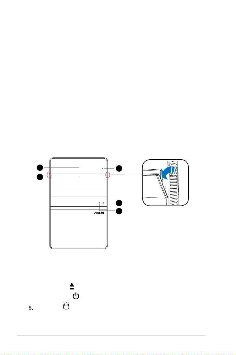
1.2 Front panel (external)
The front panel includes the system and audio control buttons, system LEDs, and
LED panel.
1. Drive door. Open this door to access the optical drive.
2. Front panel I/O cover. Open the front panel cover to show the input/output
ports.
3. Eject button . Press this button to eject the optical drive.
4. Power button . Press this button to turn the system on/off.
5. HDD LED . This LED lights up when data is being read from or written to
the hard disk drive.
2
1
4
5
3
4
Page 11
1-3ASUS CT5430
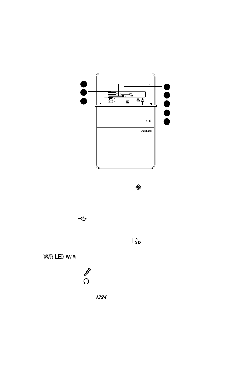
1.3 Front panel (internal)
The optical drive(s), storage card reader slots, and several I/O ports are located
inside the front panel doors.
Open the front panel cover by pushing it.
6. CompactFlash®/Microdrive™ card slot . This slot is for a
CompactFlash®/Microdrive™ storage card.
7. Memory Stick®/Memory Stick Pro™ card slot. This slot is for a Memory
Stick®/Memory Stick Pro™ storage card.
8. USB 2.0 ports
2.0
. These Universal Serial Bus 2.0 (USB 2.0) ports are
available for connecting USB 2.0 devices such as a mouse, printer, scanner,
camera, PDA, and others.
9. Secure Digital™/MultimediaCard slot . This slot is for a Secure
Digital™/MultimediaCard storage card.
10. W/R LED .This LED lights up when data is being read from or written to
the card reader.
11. Microphone port . This Mic (pink) port connects a microphone.
12. Headphone port . This port connects a headphone with a stereo mini-
plug.
13. 4-pin IEEE 1394a port . This port provides high-speed connectivity for
IEEE 1394a-compliant audio/video devices, storage peripherals, and other
PC devices.
10
6
7
8
9
11
12
13
Page 12

1-4 Chapter 1: System introduction
1.4 Rear panel
The system rear panel includes the power connector and several I/O ports that
allow convenient connection of devices.
13. Expansion slot covers. Remove these covers when installing expansion
cards.
14. LAN port. This port allows connection to a Local Area Network (LAN) through
a network hub.
15. Expansion slots. Use this slot when installing expansion card.
16. Rear surround speakers. This port connects to a high-denition six-channel
speaker.
17. Side surround speakers. This port connects to a high-denition six-channel
speaker.
18. Microphone port . This Microphone (pink) port connects a microphone.
In 4/6-channel mode, the function of this port becomes Low Frequency
Enhanced Output/Center.
19. VGA port . This port connects a VGA monitor.
20. PS/2 mouse port . This green 6-pin connector is for a PS/2 mouse.
21. COM port . This port connects a mouse, modem, or other devices that
conforms with serial specication.
22. PS/2 keyboard port . This purple 6-pin connector is for a
PS/2 keyboard.
23. USB 2.0 ports
2.0
. These Universal Serial Bus 2.0 (USB 2.0) ports are
available for connecting USB 2.0 devices such as a mouse, printer, scanner,
camera, PDA, and others.
REAR
S P K
LINE
IN
FRONT
MIC IN
SIDE
S P K
C T R
BASS
14
15
16
17
18
19
20
21
22
23
24
25
26
27
28
29
30
31
32
33
13
Page 13

1-5ASUS CT5430
24. Chassis vent. This vent is for the fan that provides ventilation inside the
system chassis.
25. Expansion card lock. This lock secures installed expansion cards. See
page 2-13 for details.
26. Center & woofer speakers. This port connects the center/subwoofer
speakers.
27. Line In port . This Line In (light blue) port connects a tape player or
other audio sources. In 6-channel mode, the function of this port becomes
Surround output.
28. Line Out port . This Line Out (lime) port connects a headphone or a
speaker. In 4/6-channel mode, the function of this port becomes Front
Speaker Out.
29. Coaxial S/PDIF Out port. This port connects an external audio output device
via a coaxial S/PIF cable.
30. Voltage selector. This switch allows you to adjust the system input voltage
according to the voltage supply in your area.
31. Power connector. This connector is for a power cable and plug.
32. Power switch. This switch allows you to turn your PC on/off.
33. 6-pin IEEE 1394a port . This port provides high-speed connectivity for
IEEE 1394a-compliant audio/video devices, storage peripherals, and other
PC devices.
The information provided is intended as a general guide for reference.
Specications are subject to the Desktop PC you purchased.
Page 14

1-6 Chapter 1: System introduction
1. ASUS motherboard
2. LGA775 socket with PnP cap
3. DIMM sockets
4. Serial ATA connectors
5. PCI Express™ x16 slot for discrete graphics
card
6. PCI slot with a LAN card
7. Expansion card slot
8. Power supply unit
1.5 Internal components
The illustration below is the internal view of the system when you remove the top
cover and the power supply unit. The installed components are labeled for your
reference. Proceed to Chapter 2 for instructions on installing additional system
components.
The illustration shows an open chassis lifted at a 90o angle.
1
2
3
4
5
6
7
8
Page 15

Chapter 2
This chapter provides step-by-step
instructions on how to install
components in the system.
Basic installation
Page 16

2-2 Chapter 2: Basic installation
R
P5L13L-X
Onboard LED
SB_PWR
ON
Standby
Power
OFF
Powered
Off
P5L13L-X
2.1 Preparation
Before you proceed, ensure that you have all the components you plan to install in
the system.
Basic components to install
1. Central Processing Unit (CPU)
2. DDR2 Dual Inline Memory Module (DIMM)
3. Expansion card(s)
4. Hard disk drive
5. Optical drive
Tool
Philips (cross) screw driver
The motherboard comes with an onboard standby power LED. This LED lights
up to indicate that the system is ON, in sleep mode or in soft-off mode, and not
powered OFF. Unplug the power cable from the power outlet and ensure that the
standby power LED is OFF before installing any system component.
•
Use a grounded wrist strap or touch a safely grounded object or a metal
object, such as the power supply case, before handling components to
avoid damaging them due to static electricity.
•
Hold components by the edges to avoid touching the ICs on them.
•
Whenever you uninstall any component, place it on a grounded antistatic
pad or in the bag that came with the component.
2.2 Before you proceed
Take note of the following precautions before you install components into the
system.
Page 17

2-3ASUS CT5430
3. Slightly pull the cover toward the
rear panel until the side tabs are
disengaged from the chassis.
4. Lift the cover, then set aside.
2. Use a Phillips screw driver to
remove the cover screws. Keep the
screws for later use.
2.3 Removing the cover
To remove the cover:
1. On the rear panel, locate the three
screws that secure the cover to the
chassis.
1 1
1
REAR
S P K
LINE
IN
FRONT
MIC IN
SIDE
S P K
C T R
BASS
4
3
3
2
2
2
Page 18

2-4 Chapter 2: Basic installation
2.4 Power supply unit
You need to turn over the power supply unit (PSU) section on the side before you
can install a central processing unit (CPU) and other system components.
To turn over the PSU:
When removing the PSU, ensure to hold or support it rmly. The unit may
accidentally drop and damage other system components.
1. Lay the system chassis on its
side on a at and stable surface.
2. Locate and remove the two
screws that secures the PSU to
the chassis.
3. Lift the PSU in the direction of
the arrow to a 90º angle.
Page 19

2-5ASUS CT5430
2.5 CPU installation
• Your boxed Intel® Pentium® 4 LGA775 processor package should
come with installation instructions for the CPU, heatsink, and the
retention mechanism. If the instructions in this section do not match
the CPU documentation, follow the latter.
•
Check your motherboard to ensure that the PnP cap is on the CPU socket
and the socket contacts are not bent. Contact your retailer immediately if
the PnP cap is missing, or if you see any damage to the PnP cap/socket
contacts/motherboard components. ASUS will shoulder the cost of repair
only if the damage is shipment/transit-related.
•
Keep the cap after installing the motherboard. ASUS will process Return
Merchandise Authorization (RMA) requests only if the motherboard comes
with the cap on the LGA775 socket.
• The product warranty does not cover damage to the socket contacts
resulting from incorrect CPU installation/removal, or misplacement/loss/
incorrect removal of the PnP cap.
2.5.1 Installing the CPU
Before installing the CPU, ensure that the socket box is facing towards you and
the load lever is on your left.
To install a CPU:
1. Locate the CPU socket on the motherboard.
To prevent damage to the
socket pins, do not remove
the PnP cap unless you are
installing a CPU.
2. Press the load lever with your thumb
(A), then move it to the left (B) until it
is released from the retention tab.
A
B
Load lever
Retention tab
R
P5L13L-X
CPU Socket 775
P5L13L-X
Page 20

2-6 Chapter 2: Basic installation
4. Lift the load plate with your thumb
and forenger to a 100º angle (4A),
then push the PnP cap from the
load plate window to remove (4B).
3. Lift the load lever in the direction of
the arrow to a 135º angle.
Load plate
PnP cap
4A
4B
3
5. Position the CPU over the socket,
making sure that the gold triangle
is on the bottom-left corner of the
socket then t the socket alignment
key into the CPU notch.
Gold
triangle
mark
Alignment key
CPU notch
6. Close the load plate (A), then push
the load lever (B) until it snaps into
the retention tab.
A
B
Page 21

2-7ASUS CT5430
2.5.2 Installing CPU fan and heatsink assembly
The Intel® Pentium® 4 LGA775 processor requires a specially designed heatsink
and fan assembly to ensure optimum thermal condition and performance.
• When you buy a boxed Intel® Pentium® 4 processor, the package
includes the CPU fan and heatsink assembly. If you buy a CPU separately,
ensure that you use only Intel®-certied multi-directional heatsink and fan.
• Your Intel
®
Pentium® 4 LGA775 heatsink and fan assembly comes in a
push-pin design and requires no tool to install.
If you purchased a separate CPU heatsink and fan assembly, ensure that the
Thermal Interface Material is properly applied to the CPU heatsink or CPU
before you install the heatsink and fan assembly.
To install the CPU heatsink and fan:
1. Place the heatsink on top of the
installed CPU, making sure that the
four fasteners match the holes on the
motherboard.
2. Push down two fasteners at a time in
a diagonal sequence to secure the
heatsink and fan assembly in place.
A
A
B
B
1
1
A
B
B
A
3. When the fan and heatsink assembly is in place, connect the CPU fan cable
to the connector on the motherboard.
Do not forget to
connect the CPU
fan connector!
Hardware
monitoring errors
can occur if you
fail to plug this
connector.
R
P5L13L-X
CPU Fan Connector
CPU_FAN
GND
CPU FAN PWR
CPU FAN IN
CPU FAN PWM
P5L13L-X
Page 22

2-8 Chapter 2: Basic installation
2.6 Installing a DIMM
The system motherboard comes with two Double Data Rate 2 (DDR2) Dual Inline
Memory Module (DIMM) sockets.
The following gure illustrates the location of the sockets:
• Installing DDR2 DIMMS other than the recommended congurations
may cause memory sizing error or system boot failure. Use any of the
recommended congurations in the table on the next page.
• Install only
identical (the same type and size) DDR2 DIMMs in DIMM_A1
and DIMM_B1.
• Always install DIMMs with the same CAS latency. For optimum
compatibility, we recommend that you obtain memory modules from the
same vendor.
• Due to chipset resource allocation, the system may detect less than 2 GB
system memory when you installed two 1 GB DDR2 memory.
• This motherboard does not support memory modules made up of 128 Mb
chips or double-sided x16 memory modules.
2.6.1 Memory congurations
You may install up to 2 GB system memory using 256 MB, 512 MB, and 1 GB
DDR2 DIMMs.
Recommended memory congurations
Sockets
DIMM_A1 DIMM_B1
Populated
Populated
Populated Populated
Mode
Single Channel
Dual-channel
R
P5L13L-X
240-pin DDR2 DIMM Sockets
128 Pins
112 Pins
DIMM_B1
DIMM_A1
P5L13L-X
Page 23

2-9ASUS CT5430
DDR2 (533 MHz) Qualied Vendors List
Siz e Ve n d or Mod el Bra nd SS /DS Co mpon ent A* B*
DI MM s uppor t
512MB KINGSTON HYB18T512800AF37 N/A SS KVR533D2N4/512 • •
1024MB KINGSTON D6408TPAGGL3U KINGSTON DS KVR533D2N4/1G • •
2048MB KINGSTON E1108AB-6E-E ELPIDA DS KVR533D2N4/2G • •
512MB Qimonda HYB18T512800BF37 N/A SS HYS64T64000HU-3.7-B •
1024MB Qimonda HYB18T512800BF37 N/A DS HYS64T128020HU-3.7-B •
256MB SAMSUNG K4T51163QC-ZCD5 SAMSUNG SS M378T3354CZ3-CD5 • •
512MB SAMSUNG ZCD5K4T51083QC SEC SS M378T6553CZ3-CD5 • •
1024MB SAMSUNG ZCD5K4T51083QC SEC DS M378T2953CZ3-CD5 • •
256MB Hynix HY5PS121621CFP-C4 Hynix SS HYMP532U64CP6-C4
1024MB Hynix HY5PS12821CFP-C4 Hynix DS HYMP512U64CP8-C4
256MB CORSAIR 32M16CEDG CORSAIR SS VS256MB533D2 • •
512MB CORSAIR MI110052432M8CEC CORSAIR DS VS512MB533D2 • •
1024MB CORSAIR 64M8CEDG CORSAIR DS VS1GB533D2 • •
512MB ELPIDA E5108AB-5C-E ELPIDA SS EBE51UD8ABFA-5C •
512MB ELPIDA E5108AB-5C-E ELPIDA SS EBE51UD8ABFA-5C-E • •
1024MB ELPIDA E5108AB-5C-E ELPIDA DS EBE11UD8ABFA-5C-E •
512MB KINGMAX E5108AE-5C-E ELPIDA SS KLBC28F-A8EB4 • •
1024MB KINGMAX E5108AE-5C-E ELPIDA DS KLBD48F-A8EB4 •
512MB KINGMAX KKEA88E4AAK-37 KINGMAX SS KLBC28F-A8KE4 •
1024MB KINGMAX 5MB22D9DCN MICRON DS KLBD48F-A8ME4 • •
512MB Apacer AM4B5708GQJS5D N/A SS AU512E533C4KBGC • •
1024MB Apacer AM4B5708GQJS5D N/A DS AU01GE533C4KBGC • •
512MB Super Talent Heat-Sink Package N/A SS T5UA512C4 • •
1024MB Super Talent Heat-Sink Package N/A DS T5UB1G8C4 • •
512MB TwinMOS K4T51083QB-GCD5 SAMSUNG SS 8D-22JB5-K2T • •
Siz e Ve n d o r Mo del B r and S S / D S Co m p one nt A* B*
DI MM s uppor t
DDR2 (667 MHz) Qualied Vendors List
512MB KINGSTON D6408TEBGGL3U KINGSTON SS KVR667D2N5/512 • •
256MB KINGSTON HYB18T256800AF3S N/A SS KVR667D2N5/256 • •
256MB KINGSTON 6SBI2D9DCG MICRON SS KVR667D2N5/256 • •
2048MB KINGSTON E1108AB-6E-E ELPIDA DS KVR667D2N5/2G
256MB Qimonda HYB18T512160BF-3S INFINEON SS HYS64T32000HU-3S-B • •
512MB Qimonda HYB18T512800BF3S N/A SS HYS64T64000HU-3S-B • •
1024MB Qimonda HYB18T512800BF3S N/A DS HYS64T128020HU-3S-B •
256MB SAMSUNG K4T51163QC-ZCE6 SAMSUNG SS M378T3354CZ0-CE6 • •
512MB SAMSUNG ZCE6K4T51083QC SEC SS M378T6553CZ0-CE6 •
256MB SAMSUNG K4T51163QC-ZCE6 SAMSUNG SS M378T3354CZ3-CE6 • •
512MB SAMSUNG K4T51083QC SEC SS M378T6553CZ3-CE6 • •
1024MB SAMSUNG ZCE6K4T51083QC SEC DS M378T2953CZ3-CE6 • •
512MB SAMSUNG K4T51163QE-ZCE6 SAMSUNG DS M378T3354EZ3-CE6 • •
256MB SAMSUNG K4T51083QE SAMSUNG SS M378T6553EZS-CE6 • •
1024MB SAMSUNG K4T51083QE SAMSUNG DS M378T2953EZ3-CE6 • •
Page 24

2-10 Chapter 2: Basic installation
DDR2 (667 MHz) Qualied Vendors List
SS - Single-sided / DS - Double - sided
DIMM support:
• A*: Supports one module inserted into any slot as Single-channel memory
conguration.
• B*: Supports one pair of modules inserted into either the yellow slots as
one pair of Dual-channel memory conguration.
Siz e Ve n d or Mo d e l B ran d S S/DS C o m pon ent A* B *
DI MM s uppor t
256MB Hynix HY5PS121621CFP-Y5 Hynix SS HYMP532U64CP6-Y5 • •
1024MB Hynix HY5PS12821CFP-Y5 Hynix DS HYMP512U64CP8-Y5 •
256MB CORSAIR MIII00605 N/A SS VS256MB667D2 • •
512MB CORSAIR 64M8CFEG N/A SS VS512MB667D2 • •
1024MB CORSAIR 64M8CFEG N/A DS VS1GB667D2 •
256MB ELPIDA E2508AB-6E-E ELPIDA SS EBE25UC8ABFA-6E-E • •
512MB ELPIDA E5108AE-6E-E ELPIDA SS EBE51UD8AEFA-6E-E • •
512MB A-DATA AD29608A8A-3EG A-DATA SS M2OAD5G3H3166I1C52 • •
1024MB A-DATA AD29608A8A-3EG A-DATA DS M2OAD5G3I4176I1C52 • •
2048MB A-DATA NT5TU128M8BJ-3C N/A DS M2ONY5H3J4170I1C5Z
512MB crucial Heat-Sink Package N/A SS BL6464AA663.8FD • •
1024MB crucial Heat-Sink Package N/A DS BL12864AA663.16FD • •
1024MB crucial Heat-Sink Package N/A DS BL12864AL664.16FD • •
1024MB crucial Heat-Sink Package N/A DS BL12864AA663.16FD2 • •
512MB Apacer AM4B5708GQJS7E0628F APACER SS AU512E667C5KBGC • •
1024MB Apacer AM4B5708GQJS7E APACER DS AU01GE667C5KBGC
512MB Transcend K4T51083QE SAMSUNG SS TS64MLQ64V6J • •
1024MB Transcend K4T51083QE SAMSUNG DS TS128MLQ64V6J • •
256MB Kingmax N2TU51216AG-3C NANYA SS KLCB68F-36KH5 • •
512MB Kingmax KKEA88B4LAUG-29DX KINGMAX SS KLCC28F-A8KB5 •
1024MB Kingmax KKEA88B4LAUG-29DX KINGMAX DS KLCD48F-A8KB5 •
512MB Super Talent Heat-Sink Package N/A SS T6UA512C5 • •
1024MB Super Talent Heat-Sink Package N/A DS T6UB1GC5 • •
2048MB NANYA NT5TU128M8BJ-3C NANYA DS NT2GT64U8HB0JY-3C •
512MB NANYA NT5TU64M8BE-3C NANYA SS NT512T64U88B0BY-3C •
512MB PSC A3R12E3GEF637BLC5N PSC SS AL6E8E63B-6E1K • •
1024MB PSC A3R12E3GEF637BLC5N PSC DS AL7E8E63B-6E1K • •
512MB TwinMOS E5108AE-GE-E ELPIDA SS 8G-25JK5-EBT •
512MB TwinMOS TMM6208G8M30C TwinMOS SS 8D-23JK5M2ETP • •
Visit the ASUS website for the latest DDR2-667/553MHz QVL.
Page 25

2-11ASUS CT5430
2.6.2 DIMM installation
To install a DDR2 DIMM:
1. Locate the two DIMM sockets on the motherboard.
2. Unlock a socket by pressing the retaining clips
outward.
3. Align a DIMM on the socket such that the notch on
the DIMM matches the break on the socket.
4. Firmly insert the DIMM into the socket until the
retaining clips snap back in place and the DIMM is
properly seated.
A DDR2 DIMM is keyed with a notch so that it ts in only one direction. DO NOT
force a DIMM into a socket to avoid damaging the DIMM!
Page 26

2-12 Chapter 2: Basic installation
2.7 Installing an expansion card
In the future, you may need to install expansion cards. The motherboard has one
PCI and one PCI Express™ x16 slot. The following sub-sections describe the slots
and the expansion cards that they support.
2.7.1 Expansion slots
Make sure to unplug the power cord before adding or removing expansion
cards. Failure to do so may cause you physical injury and damage the
motherboard.
PCI Express™ x16 slot
This motherboard supports PCI
Express™ x16 graphic cards
that comply with PCI Express™
specications. The gure shows a
graphics card installed on the PCI
Express™ x16 slot.
The chassis supports PCI Express x 16 cards with 192 mm x 19 mm or smaller
dimensions only.
Page 27

2-13ASUS CT5430
2.7.2 Expansion card installation
To install an expansion card:
1. Before installing the expansion card, read the documentation that came with
it and make the necessary hardware settings for the card.
2. Locate and remove one metal bracket lock screw.
3. Remove the metal bracket lock.
4. Align the card connector with the slot, then press rmly.
5. Secure the card with one screw.
6. Replace the metal braket lock, then secure it with one screw.
Standard interrupt assignments
IRQ Sta ndar d Fun ctio n
0 System Timer
1 Keyboard Controller
2 Programmable Interrupt
4 Communications Port (COM1)
6 Floppy Disk Controller
7* Printer Port (LPT1)
8 System CMOS/Real Time Clock
9* ACPI Mode when used
10* IRQ Holder for PCI Steering
11* IRQ Holder for PCI Steering
12* PS/2 Compatible Mouse Port
13 Numeric Data Processor
14* Primary IDE Channel
* These IRQs are usually available for ISA or PCI devices.
3
4
6
5
1
2
Page 28

2-14 Chapter 2: Basic installation
When using a PCI card on shared slots, ensure that the drivers support “Share
IRQ” or that the cards do not need IRQ assignments. Otherwise, conicts will
arise between the two PCI groups, making the system unstable and the card
inoperable.
A B C D E F G H
PCI slot shared shared shared shared –– –– –– ––
PCI Express x16 slot shared –– –– –– –– –– –– ––
Onboard USB controller 1 –– –– –– –– shared –– –– ––
Onboard USB controller 2 –– shared –– –– –– –– –– ––
Onboard USB controller 3 –– –– shared –– –– –– –– ––
Onboard USB controller 4 –– –– –– shared –– –– –– ––
Onboard USB 2.0 controller –– –– –– –– shared –– –– ––
Onboard IDE port –– –– shared –– –– –– –– ––
Onboard AC’ 97 Audio shared –– –– –– –– –– –– ––
Onboard LAN shared –– –– –– –– –– –– ––
Onboard 1394 –– –– –– –– shared –– –– ––
IRQ assignments for this motherboard
2.8 Installing an optical drive
The Desktop PC comes with a 5.25-inch drive bays for an optical drive.
To install an optical drive:
1. Place the chassis upright.
2. Insert the optical drive to the upper
5.25 in drive bay, then carefully
push the drive until its screw holes
align with the holes on the bay.
22
3 3
3. Secure the optical drive with four
screws on both sides of the bay.
4. Connect the IDE and the power
plugs to the connectors at the back
of the drive.
Page 29

2-15ASUS CT5430
2.9 Installing a Serial ATA disk drive
The system supports one Serial ATA hard disk drive.
To install a Serial ATA hard disk drive:
1. Connect the SATA power cable to
the plug of the power supply unit.
1
2
4
4
4
4
4
2. Connect the SATA signal cable and
the power plugs to the connectors
at the back of the drive.
4. Insert a hard disk drive (with the
HDD PCB facing the top of the
chassis) to the tray, then secure it
with four screws.
5. Connect the SATA signal cable to the
SATA connector on the motherboard,
and tighten all the cables with the
plastic coils.
3. Locate the HDD tray.
Page 30

2-16 Chapter 2: Basic installation
2.10 Replacing the power supply unit
Replace the power supply unit (PSU) after installing the system components and
reconnecting the cables.
To replace the PSU:
Make sure the PSU cables do not interfere with the CPU and/or chassis fans.
Voltage selector
The PSU has a 115 V/230 V voltage selector switch
located beside the power connector. Use this switch to
select the appropriate system input voltage according
to the voltage supply in your area.
If the voltage supply in your area is 100-127 V, set the
switch to 115 V.
If the voltage supply in your area is 200-240 V, set the
switch to 230 V.
Setting the switch to 115 V in a 230 V environment will seriously damage the
system!
1. If necessary, connect the 4-pin
12V power plug to the ATX12V
connector on the motherboard.
2. If necessary, connect the 24-pin
ATX power plug to the ATXPWR
connector on the motherboard.
3. Connect the optical drive power
connector.
4. Lift the PSU in the direction of
the arrow until it properly ts in
place.
5. Secure the PSU with the screws
you removed earlier.
Page 31

2-17ASUS CT5430
2.11 Replacing the cover
To replace the cover:
1. Turn the chassis upright.
2. Position the front edge of the cover
at least two inches from the front
panel cover. Fit the cover tabs with
the chassis rail and the front panel
tabs.
3. Lower the rear edge of the cover as
shown.
4. Push the cover slightly toward the
front panel until it ts in place.
5. Secure the cover with the three
screws you removed earlier.
2
3
4
5
Page 32

2-18 Chapter 2: Basic installation
Page 33

Appendix
Appendix
The Appendix includes the information
on recovering your system, and
troubleshooting.
Page 34

A-2 Appendix
A.1 Recovering your system
Using the recovery DVD
The recovery DVD includes an image of the operating system installed on your
system at the factory. The recovery DVD,
working with the support DVD, provides a comprehensive
recovery solution that quickly restores your system to its original working state,
provided that your hard disk drive is in good
working order. Before using the recovery DVD, copy your data les (such as
Outlook PST les) to a USB device or to a network drive and make note of any
customized conguration settings (such as network settings).
1. Turn on your ASUS Desktop PC and the ASUS logo appears. Press
F8 to
enter the Please select boot device menu.
2. Insert the recovery DVD into the optical drive and select the optical drive
(“CDROM:XXX”) as the boot device. Press Enter and then press any key to
continue.
3. The
Windows Boot Manager window appears. Select Windows Setup
[EMS Enabled] and press Enter. Wait when the Windows is loading les
message appears.
4. Select where to install a new system. Options are:
Recover system to a partition
This option will delete only the partition you select from
below, allowing you to keep other partitions, and create a new system
partition as drive “C.” Select a partition and click NEXT.
Recover system to entire HD
This option will delete all partitions from your hard disk drive and create a
new system partition as drive “C.” Select and click Yes.
5. Follow the on-screen instructions to complete the recovery process.
6. After the system recovery is completed, you will be asked to insert the
support DVD into the optical drive. Click OK and the system reboots.
7. After the system reboots, Windows® Vista™ will begin system congurations.
Follow the on-screen instructions to complete the process, and then restart
the computer.
You will lose all your data during the system recovery. Make sure that you make
a backup of it before recovering the system.
This recovery DVD is for ASUS Desktop PC only. DO NOT use it on other
computers. Visit the ASUS website www.asus.com for any updates.
Page 35

A-3ASUS CT5430
Read the following Q&As for troubleshooting guide. If these do not give you
answers, you may contact us directly at the contact information provided in the
support DVD.
What can I do if my Desktop PC cannot be powered on?
Check if the power LED on the front panel lights up. It does not light up if no power
is supplied to the system.
• Find out if the power cord is plugged in.
• When you use an extension cord or a voltage regulator, ensure that you have
plugged it into the wall socket and switched it on.
What can I do if my Desktop PC cannot enter the operating system?
• Make sure that you use memory modules that the system supports and that
you install them properly on the sockets.
• Check if your peripheral devices are compatible with the
system. Some USB storage devices, for example, are with
different disk drive structure and enter sleep mode easily.
If the above steps do not solve the problem, contact your retailer or perform
system recovery using the supplied recovery DVD.
A.2 Troubleshooting
You will lose all your data during the system recovery. Make sure that you make
a backup of it before recovering the system.
Why is it that I cannot hear anything from my speakers/headphones?
Check the volume icon on the Windows® taskbar to see if it is set to mute .
If so, double-click this icon to display the volume bar, and then click the mute icon
under the bar to cancel the muted mode .
Why is it that a CD/DVD cannot be read from or written to?
• Make sure that you use a disc compatible with the optical drive.
• Check if you insert the disc properly or if there is any scratch on the disc.
• Find out if the disc is with write protection.
Page 36

A-4 Appendix
 Loading...