

Page 1
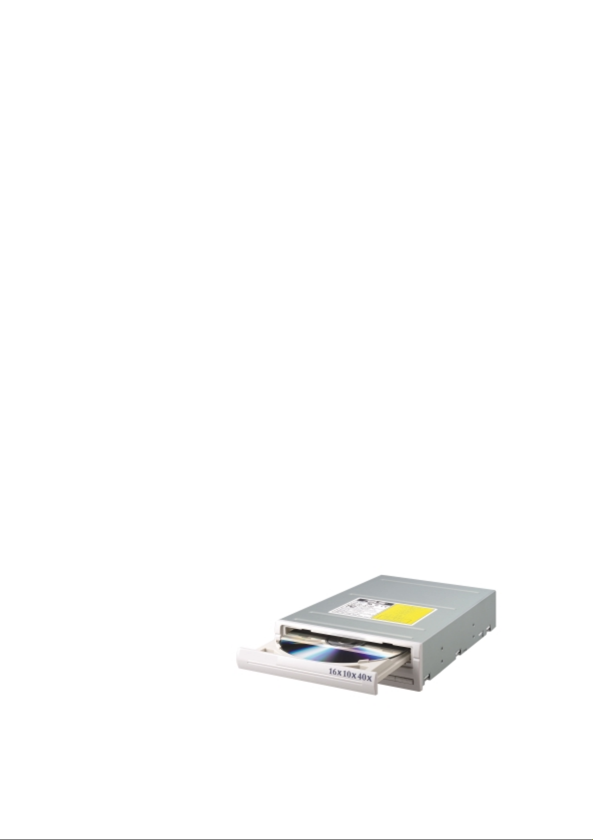
CRW-1610A
16x/10x/40x CD-RW Drive
User’s Manual
Page 2

Copyrights/Disclaimer
Checklist
No part of this manual, including the products and software described in it, may be
reproduced, transmitted, transcribed, stored in a retrieval system, or translated into any
language in any form or by any means, except documentation kept by the purchaser for
backup purposes, without the express written permission of the manufacturer.
THE MANUFACTURER PROVIDES THIS MANUAL “AS IS” WITHOUT WARRANTY OF ANY
KIND, EITHER EXPRESS OR IMPLIED, INCLUDING BUT NOT LIMITED TO THE IMPLIED
WARRANTIES OR CONDITIONS OF MERCHANTABILITY OR FITNESS FOR A
PARTICULAR PURPOSE. IN NO EVENT SHALL THE MANUFACTURER, ITS DIRECTORS,
OFFICERS, EMPLOYEES OR AGENTS BE LIABLE FOR ANY INDIRECT, SPECIAL,
INCIDENTAL, OR CONSEQUENTIAL DAMAGES (INCLUDING DAMAGES FOR LOSS OF
PROFITS, LOSS OF BUSINESS, LOSS OF USE OR DATA, INTERRUPTION OF
BUSINESS AND THE LIKE), EVEN IF THE SAME HAS BEEN ADVISED OF THE
POSSIBILITY OF SUCH DAMAGES ARISING FROM ANY DEFECT OR ERROR IN THIS
MANUAL OR PRODUCT.
Product warranty or service will not be extended if: (1) the product is repaired, modified or
altered, unless such repair, modification of alteration is authorized in writing by the
manufacturer; or (2) the serial number of the product is defaced or missing.
The product name and revision number are both printed on the product itself. Manual
revisions are released for each product design represented by the digit before and after the
period of the manual revision number. Manual updates are represented by the third digit in
the manual revision number.
SPECIFICATIONS AND INFORMATION CONTAINED IN THIS MANUAL ARE FURNISHED
FOR INFORMATIONAL USE ONLY, AND ARE SUBJECT TO CHANGE AT ANY TIME
WITHOUT NOTICE, AND SHOULD NOT BE CONSTRUED AS A COMMITMENT BY THE
MANUFACTURER. THE SAME ASSUMES NO RESPONSIBILITY OR LIABILITY FOR ANY
ERRORS OR INACCURACIES THAT MAY APPEAR IN THIS MANUAL, INCLUDING THE
PRODUCTS AND SOFTWARE DESCRIBED IN IT.
Products and corporate names appearing in this manual may or may not be registered
trademarks or copyrights of their respective companies, and are used only for identification or
explanation and to the owners’ benefit, without intent to infringe.
Product Name: CRW-1610A
Manual Revision: 1.00 E872
Release Date: September 2001
2
Page 3

Contents
Copyrights/Disclaimer....................................................... 2
FCC/CDC Statements ........................................................ 4
Safety Information ............................................................. 5
Installation Notices....................................................... 5
Using the Device.......................................................... 6
Package Contents.............................................................. 7
Welcome! ............................................................................ 8
Product Introduction ......................................................... 8
Specifications............................................................... 8
Welcome! ............................................................................ 8
Product Introduction ......................................................... 8
Specifications............................................................... 8
Features....................................................................... 9
Front Panel ................................................................ 11
Rear Panel................................................................. 12
Installation ........................................................................ 13
System Requirements ............................................... 13
Setting the Jumper Terminals .................................... 14
Installing the CD-RW Drive........................................ 15
Connecting the Drive Cables ..................................... 17
Installing the Device Driver............................................. 18
Installing the CD-RW Software ....................................... 18
CD-RW Drive Basics ........................................................ 19
Placing a Disc into the Drive...................................... 19
Ejecting a Disc from the Drive ................................... 20
Using the Emergency Eject Pinhole .......................... 21
Using Compact Discs ...................................................... 22
Cleaning a Disc.......................................................... 22
Handling a Disc.......................................................... 22
Technical Information ...................................................... 23
Environmental Specifications..................................... 23
Electrical and Audio Specifications ............................ 23
NOTES............................................................................... 24
3
Page 4

FCC/CDC Statements
Federal Communications Commission Statement
This device complies with FCC Rules Part 15. Operation is subject to the following
two conditions:
• This device may not cause harmful interference, and
• This device must accept any interference received including interference that
may cause undesired operation.
This equipment has been tested and found to comply with the limits for a Class B
digital device, pursuant to Part 15 of the FCC Rules. These limits are designed to
provide reasonable protection against harmful interference in a residential
installation. This equipment generates, uses and can radiate radio frequency
energy and, if not installed and used in accordance with manufacturer’s
instructions, may cause harmful interference to radio communications. However,
there is no guarantee that interference will not occur in a particular installation. If
this equipment does cause harmful interference to radio or television reception,
which can be determined by turning the equipment off and on, the user is
encouraged to try to correct the interference by one or more of the following
measures:
• Reorient or relocate the receiving antenna.
• Increase the separation between the equipment and receiver.
• Connect the equipment to an outlet on a circuit different from that to which the
receiver is connected.
• Consult the dealer or an experienced radio/TV technician for help.
WARNING! The use of shielded cables for connection of the monitor to
the graphics card is required to assure compliance with FCC regulations.
Changes or modifications to this unit not expressly approved by the party
responsible for compliance could void the user’s authority to operate this
equipment.
Canadian Department of Communications Statement
This digital apparatus does not exceed the Class B limits for radio noise emissions
from digital apparatus set out in the Radio Interference Regulations of the
Canadian Department of Communications.
This class B digital apparatus complies with Canadian ICES-003.
4
Page 5
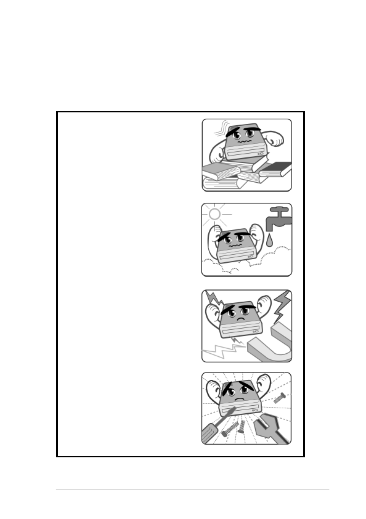
Safety Information
Observe the following precautions before installing and using the
CRW-1610A Drive!
Installation Notices
Do not place this device in an
unstable position, or in one that
vibrates.
Do not place this device in areas
where there is direct sunlight,
high humidity, or damp condition.
Do not use or place this device
near magnetic fields, televisions,
or radios, where there is
interference that may affect the
performance of the drive.
Do not attempt to disassemble or
repair the drive. Opening the drive
may result to exposure to laser
radiation.
5
Page 6

Safety Information
Using the Device
• Do not move the device from a cold to a warm or hot environment.
Drastic change of temperature is harmful to the device.
• Before moving or uninstalling the drive, remove a disc from it, if any.
• Prevent liquids or any metal to get into the device. If this situation
occurs, contact your retailer for help.
• Do not use any evaporating solvents to clean the device. If you
accidentally sprayed any solvent on the device, use a clean cloth to
wipe it. You may also use a neutral cleaner to dilute the solvent to
easily wipe it from the device.
• Try not to interrupt the supply of power while the device is in reading or
writing mode.
• Do not place damaged discs inside the device.
• Do not place discs into the device immediately if they came from a cold
environment, specially during cold seasons. Wait until the discs have
reached room temperature.
6
Page 7

Package Contents
Upon opening your CRW-1610A drive package, check if all the following
items are present and in good condition. If any of the items is damaged or
missing, contact your retailer immediately.
• Cable set (With an Audio Cable and 4 Screws)
• CD Recording Software
• This User’s Manual
• Quick Installation Guide in 11 Different Languages
7
Page 8

Welcome!
Thank you for buying the CRW-1610A Drive!
To ensure proper installation and use of this device, read the instructions
and other important information contained in this manual.
Product Introduction
Specifications
The CRW-1610A has the following specifications.
• Speeds 16X writes
10X rewrites
40X reads
• Interface ATAPI specification
• Technology support FlextraLink™ Technology
Double Dynamic Suspension System II
(DDSS II)
• Data buffer size 2MB
• Application discs 12cm or 8cm diameter, 1.2mm thick
CD-Audio, CD-ROM, CD-ROM/XA, CD-I,
Mixed Mode CD-ROM, Photo CD, CD-Extra,
Video CD, CD-Text, DVCD, CD-G, Karaoke
CD, I-trax
• Recording form Orange Book Part 2, 3
Disc-at-once, Track-at-once
Session-at-once, Packet write
• OS compatibility MS-Windows 98/98SE/ME/2000,
Windows NT, SCO Unix, Linux,
OS/2 Warp
• Power supply DC 5 x (1 +/- 5%)V
DC 12 x (1 +/- 10%)V
• Dimensions 41.5 (h) x 149.0 (w) x 197.5 (d) mm
• Mass 997 g
NOTE: Refer to the section “Technical Information” on page 24 for detailed
specifications.
8
Page 9

Features
The CRW-1610A is a CD-RW drive with 16X-write, 10X-rewrite, and 40Xread capabilities. The drive complies with the AT Attachment Packet
Interface (ATAPI) specification and comes equipped with the latest
innovative technologies in CD recording.
FlextraLink™ Technology
The FlextraLink technology incorporates a flexible strategy to free you
from buffer underrun problems caused by an empty data buffer. This
CD-RW drive technology allows continuous monitoring of the data buffer
status during the write process. If the available data drops below 1% of the
total buffer capacity, the drive stops recording and marks the last write
position. When new data is received from the host, it is loaded to the data
buffer, and the laser is repositioned to link the new data with the data
already written. This technology also ensures that your PC remains fully
operational throughout the writing process, and available for other
applications.
The diagram below shows the advantage of the FlextraLink recording
technology.
FlextraLink™ Technology Solution
Conventional
Recording
Data
Buffer
Write Data
Memory
Recording with
FlextraLink™
Technology
Data
Write Data
Data
Write Data
Data transfer
slows down
Buffer
Memory
Write process
continues
Data transfer
slows down
Buffer
Memory
Write process stops;
waits until there is
enough data for writing
Data
Buffer
Memory
Empty
Data
Write Data
Data transfer slower
than write process
Bad disc results
Data transfer continues
and fills buffer with
sufficient data for writing
Buffer
Memory
Write process continues
until writing is complete
CRW-1610A User’s Manual
9
Page 10

Double Dynamic Suspension System (DDSS II)
The DDSS II is an enhanced follow up to the DDSS anti-vibration system
developed by ASUSTeK. The DDSS CD-ROM technology is designed to
reduce the vibration generated from spindle rotation of over 8900 rpm of
40X CD-ROM drives. The DDSS II improves this feature by handling up to
over 10,000 rpm of the new 50X drives. In addition, the DDSS II stabilizes
the pick-up head of the drive in both horizontal and vertical directions,
making tracking and focusing even more precise.
Like the DDSS, the DDSS II vibration absoption structure contains a
“dynamic mass” that can absorb the vibration caused by high revolution of
spindle motor. However, the DDSS II moves the dynamic mass to be
suspended to the chassis, thus providing more stability and accuracy
when accessing data from the disc.
The following diagram illustrates the DDSS/DDSS II design structure.
DDSS / DDSS II Design Structure
10
CRW-1610A User’s Manual
Page 11

Front Panel
16x10x40x
R
6
7 8
12
Recordable
Recordable
Recordable
Rewritable
High Speed
3 54
W
1. Headphone jack
This jack allows you to connect a headphone with a stereo mini-plug.
2. Headphone volume dial
This volume dial allows you to control the volume of the headphone
connected to the drive. Turning the dial to the left decreases the
volume, turning to the right increases volume.
3. Disc tray
This tray holds the disc.
4. WRITE indicator (Red LED)
This LED flashes while data is being written on the disc.
5. READ indicator (Green LED)
This LED turns ON when you place a disc on the drive tray, and stays
ON until you remove the disc. The LED flashes while data is being
read from the disc.
6. Emergency eject pinhole
In cases when you cannot eject a disc from the drive using the eject
button due to power failure or software problems, insert a pin or a
paper clip into this hole to manually eject the tray and the disc.
7. PLAY/SKIP button
This button has two functions. If the drive is idle, pressing this button
will start playing an audio disc (if one is currenly loaded in the drive)
from the first track. While in the PLAY mode, pressing this button lets
you skip to the next track on the disc.
8. STOP/EJECT button
This button has two functions. Pressing this button at any time ejects
the disc tray so you can place or remove a disc. While in PLAY mode,
pressing this button stops playing the disc loaded in the drive.
CRW-1610A User’s Manual
11
Page 12

Rear Panel
1 32 4 5
1. Digital audio connector
This connector is for a digital signal output cable.
2. Analog audio connector
This connector is for an analog signal output cable.
3. Jumper terminals
These pins allow you to select either Master, Slave, or Cable Select
mode for the CD-ROM device.
4. IDE connector
This connector is for a 40-pin IDE cable to connect the drive to the IDE
interface on the motherboard.
5. Power connector
This DC connector is for a 4-pin power cable from the system power
supply.
NOTE: The jumper pins on the leftmost part of the rear panel are
factory test pins. DO NOT cover these pins with jumper blocks.
12
CRW-1610A User’s Manual
Page 13

Installation
System Requirements
Before installing and using the CD-RW drive, make sure that your
computer system meets the following requirements.
• IBM-compatible Pentium 166MHz or higher PC
• Windows 98/98SE/ME/2000, Windows NT, Linux, or OS/2 Warp
operating system
• At least 64MB system memory (128MB is recommended)
• An empty 5.25-inch external drive bay
• HDD empty storage capacity of 100MB or more
Average seek time: 20ms or less
Transmission rate: 2 MB/s or more
NOTE: Do not use a hard disk that calibrates thermally during
operation.
• Recommended media:
CD-R (x2 ~ x16) TAIYOYUDEN, MITSUMI CHEMICAL,
MITSUBISHI CHEMICAL, RICOH, RITEK,
PRINCO, KODAK
CD-RW (x2 ~ x10) RITEK, RICOH, YAMAHA, GIGASTORAGE
CD-RW (x2 ~ x4) MITSUBISHI CHEMICAL, RICOH, RITEK
CRW-1610A User’s Manual
13
Page 14

Setting the Jumper Terminals
Configure the the jumpers to set the device to master or slave mode
before physically installing it to your computer chassis. Use jumper blocks
to short the pins to your desired setting.
CAUTION: Make sure to correctly place the jumper blocks over the
pins. Failure to do so may cause irreparable damage to the drive!
Jumper Terminals
Master Mode
Cover the two pins labeled MASTER to set the CD-RW
drive as a secondary master drive. This is possible only if
your computer supports four IDE devices. The hard disk in
the computer is set as Primary Master.
Slave Mode
Cover the two pins labeled SLAVE to set the CD-RW drive
as a slave device if your computer supports only two IDE
devices.
If your computer supports four IDE devices, this setting
sets your CD-RW drive either as a Primary Slave or a
Secondary Slave.
Cable Select Mode
14
Cover the two pins labeled CABLE SELECT if your
computer supports a Cable Select (CSEL) signal. You
need an exclusive interface cable for this setting. Refer to
your computer manual for details.
CRW-1610A User’s Manual
Page 15

Installing the CD-RW Drive
Follow these steps to install the drive into the computer chassis.
NOTE: Refer to your computer manual for specific instructions on
opening the chassis and installing drives.
1. Remove the cover of an empty 5.25-inch external drive bay.
2. Carefully insert the CD-RW drive into the bay and push it inward until it
is flushed to the chassis front panel. The holes on the sides of the drive
should align with the holes on the drive bay.
CRW-1610A User’s Manual
15
Page 16

3. Secure the drive with screws that came with the drive package. Use
two screws on each side of the drive.
IMPORTANT: Depending on the space on your chassis, you may
need to connect the drive cables before securing the drive into the
chassis. For cable connections, proceed to the following section,
“Connecting the Drive Cables.”
16
CRW-1610A User’s Manual
Page 17

Connecting the Drive Cables
1. Connect the power cable plug to the power connector on the rear
panel.
2. Connect the 40-pin IDE cable plug to the IDE connector, matching the
red pin stripe on the cable with Pin 1 on the connector.
3. If your computer has a sound card or an onboard audio feature,
connect an audio interface cable to the 4-pin analog audio connector
on the rear of the drive. Connect the other end of the audio cable to the
connector on the sound card or on the 4-pin CD connector on the
motherboard.
CAUTION! All the cable plugs are slotted so that they fit in only one
orientation. If a plug does not fit in completely, try reversing it. DO
NOT use too much force when fitting the cable plugs.
Power Cable
4-pin Audio Cable
IDE Cable
NOTE: Replace the computer cover according to your computer
manual.
CRW-1610A User’s Manual
17
Page 18

Installing the Device Driver
Before you can use your CRW-1610A drive, you must first install the
device driver.
IMPORTANT! Make sure you that you have completed the drive
installation and have replaced the computer cover before you
proceed.
Follow these steps to install the device driver.
1. Turn on the computer.
2. Your operating system (OS) detects the new hardware (CD-RW drive)
that you installed and automatically looks for the appropriate driver.
3. Follow the screen instructions to install the driver.
Installing the CD-RW Software
The CRW-1610A drive supports the following software applications.
By AHEAD software GmbH
• Nero Burning ROM
• In CD
• Wave Editor
• Cover Designer
By Microsoft Corporation
• Media Player
• CD Player
• Active Movie
By Kodak
• Kodak Photo CD Player, V2.0 or higher
18
NOTE: Refer to the manuals that came with the specific software
for installation instructions.
CRW-1610A User’s Manual
Page 19

CD-RW Drive Basics
Placing a Disc into the Drive
1. Press the eject button on the front of the drive to eject the tray.
2. When the drive tray ejects out of the drive, place the disc on the tray
with the label (printed) side up.
CRW-1610A User’s Manual
19
Page 20

NOTE: If you are using a 12-cm disc, place it on the tray making
sure that it fits the outer circular border. This border helps hold the
disc in place. If you are using an 8-cm disc, place it on the inner
circular border on the tray.
12-cm Disc
8-cm Disc
3. Press the drive eject button or lightly push the center of the drive tray
to replace the tray inside the drive.
Ejecting a Disc from the Drive
1. Press the eject button on the front of the drive to eject the tray.
2. Carefully remove the disc from the tray.
3. Press the drive eject button or lightly push the center of the drive tray
to load the tray back into the drive.
20
CRW-1610A User’s Manual
Page 21

Using the Emergency Eject Pinhole
The emergency eject pinhole on the front of the drive allows you to
manually eject the drive tray and remove a disc from the drive in the
following instances:
• supply of power to the computer is cut due to electrical power outage
• the drive malfunctions
CAUTION! Use the manual method only as a last resort when the
eject button does not work. Make sure that you have turned off your
computer before attempting to eject the drive tray.
Follow these steps to eject the drive tray using the emergency pinhole.
1. Insert a pointed rod, such as a pin, a needle, or paper clip, small
enough to fit into the emergency pinhole.
2. Carefully pull the tray out and remove the CD.
CRW-1610A User’s Manual
21
Page 22

Using Compact Discs
Take note of the instructions in this section when using compact discs.
These instructions will help you avoid damaging the discs and your
CD-RW drive.
Cleaning a Disc
Spray the disc with compressed air for about five seconds to get rid of the
dust on a disc.
Handling a Disc
Hold a disc by the edges. Do not touch the disc surface.
22
CRW-1610A User’s Manual
Page 23

Technical Information
Environmental Specifications
Temperature Operation: 5°C < to < 45°C
Storage: - 20°C to < 60°C
Humidity Operation: 20% to 80% non-condensing
Storage: 15% to 85% non-condensing
Vibration Operation: 0.3G peak at 5 ~ 500 Hz
Storage: 2.0G peak at 10 ~ 500 Hz
Impact Non-operation: 1 oct/min – no damage
Less than 50G –
(at 11ms/half sine wave,
3 shock/each side)
Packaged: 1 oct/min – no damage
91 cm high –
(1 corner, 3 edges, 6 surfaces)
Acoustic Access mode: 45.5 dB TYP
Read mode: 45.0 dB TYP
(Microphone located 50cm in front of the drive, 120cm above the drive at 30°
angle.)
Reliability MTBF: 100,000 power on hours
ODC (Read): 20% of power on time
ODC (Write): 1% of power on time
Mean Time To Repair (MTTR) 30 minutes
* ODC - Operating Duty Cycle
Electrical and Audio Specifications
Power Source Voltage +5V DC +12V DC
Tolerance +/- 5% +/- 10%
Ripple 150m Vpp 300m Vpp
Rating 900mA 1500mA
I/O Terminal Power connector 4-pin +5V, +12V
ATAPI terminal 40-pin
Audio out 4-pin (analog)
2-pin (digital)
Audio No. of channels 2 (stereo)
Sampling frequency 44.1 kHz
Quantization 16 bits
Distortion 0.2% max. (at 1 kHz)
S/N ratio 70 dB
Output: Headphone 0.7 V rms (typical)
Line Out 0.7 V rms (typical)
CRW-1610A User’s Manual
23
Page 24

15-xxxxxxxxx
 Loading...