

Page 1

Index
English ............................................................................1
Deutsch.........................................................................73
Français ...................................................................... 145
Italiano ........................................................................219
Español .......................................................................293
Nederlands .................................................................365
Português ...................................................................437
Page 2

Page 3
ASUS Desktop PC
BM6635(MD560)
BM6835
BP6335(SD560)
BM6635(MD560)
User Manual
BM6835
BP6335(SD560)
Page 4

ENGLISH
ENGLISH
E7286
First Edition
May 2012
Copyright © 2012 ASUSTeK Computer Inc. All Rights Reserved.
No part of this manual, including the products and software described in it, may be reproduced,
transmitted, transcribed, stored in a retrieval system, or translated into any language in any form or by any
means, except documentation kept by the purchaser for backup purposes, without the express written
permission of ASUSTeK Computer Inc. (“ASUS”).
Product warranty or service will not be extended if: (1) the product is repaired, modied or altered, unless
such repair, modication of alteration is authorized in writing by ASUS; or (2) the serial number of the
product is defaced or missing.
ASUS PROVIDES THIS MANUAL “AS IS” WITHOUT WARRANTY OF ANY KIND, EITHER EXPRESS
OR IMPLIED, INCLUDING BUT NOT LIMITED TO THE IMPLIED WARRANTIES OR CONDITIONS OF
MERCHANTABILITY OR FITNESS FOR A PARTICULAR PURPOSE. IN NO EVENT SHALL ASUS, ITS
DIRECTORS, OFFICERS, EMPLOYEES OR AGENTS BE LIABLE FOR ANY INDIRECT, SPECIAL,
INCIDENTAL, OR CONSEQUENTIAL DAMAGES (INCLUDING DAMAGES FOR LOSS OF PROFITS,
LOSS OF BUSINESS, LOSS OF USE OR DATA, INTERRUPTION OF BUSINESS AND THE LIKE),
EVEN IF ASUS HAS BEEN ADVISED OF THE POSSIBILITY OF SUCH DAMAGES ARISING FROM ANY
DEFECT OR ERROR IN THIS MANUAL OR PRODUCT.
SPECIFICATIONS AND INFORMATION CONTAINED IN THIS MANUAL ARE FURNISHED FOR
INFORMATIONAL USE ONLY, AND ARE SUBJECT TO CHANGE AT ANY TIME WITHOUT NOTICE,
AND SHOULD NOT BE CONSTRUED AS A COMMITMENT BY ASUS. ASUS ASSUMES NO
RESPONSIBILITY OR LIABILITY FOR ANY ERRORS OR INACCURACIES THAT MAY APPEAR IN THIS
MANUAL, INCLUDING THE PRODUCTS AND SOFTWARE DESCRIBED IN IT.
Products and corporate names appearing in this manual may or may not be registered trademarks or
copyrights of their respective companies, and are used only for identication or explanation and to the
owners’ benet, without intent to infringe.
2
Page 5

Contents
ENGLISH
Notices .......................................................................................................... 5
Safety information .......................................................................................... 7
Conventions used in this guide ...................................................................... 8
Where to nd more information ..................................................................... 8
Package contents .......................................................................................... 9
Chapter 1: Getting started
Welcome! ......................................................................................................11
Getting to know your computer .....................................................................11
Setting up your computer ............................................................................. 21
Turning your computer ON/OFF .................................................................. 26
Chapter 2: Using Windows® 7
Starting for the rst time ............................................................................... 27
Using Windows® 7 desktop .......................................................................... 28
Managing your les and folders ................................................................... 30
Restoring your system settings .................................................................... 32
Protecting your computer ............................................................................. 33
Getting Windows® Help and Support ........................................................... 34
Chapter 3: Connecting devices to your computer
Connecting a USB storage device ............................................................... 35
Connecting microphone and speakers ........................................................ 37
ENGLISH
Chapter 4: Using your computer
Proper posture when using your Desktop PC.............................................. 41
Using the optical drive (on selected models only) ....................................... 42
Conguring the USB ports using the BIOS .................................................. 43
Chapter 5: Connecting to the Internet
Wired connection ......................................................................................... 45
Chapter 6: Using the utilities
ASUS AI Suite II ........................................................................................... 49
ASUS WebStorage ...................................................................................... 56
ASUS Easy Update ..................................................................................... 58
ASUS Secure Delete ................................................................................... 59
ASUS Business Suite .................................................................................. 60
3
Page 6

Contents
ENGLISH
ENGLISH
Nero 9 ........................................................................................................ 62
Recovering your system .............................................................................. 63
Chapter 7: Troubleshooting
Troubleshooting ........................................................................................... 65
ASUS contact information ............................................................................ 72
4
Page 7

Notices
ENGLISH
ASUS Recycling/Takeback Services
ASUS recycling and takeback programs come from our commitment to the highest standards
for protecting our environment. We believe in providing solutions for you to be able to
responsibly recycle our products, batteries, other components, as well as the packaging
materials. Please go to http://csr.asus.com/english/Takeback.htm for the detailed recycling
information in different regions.
REACH
Complying with the REACH (Registration, Evaluation, Authorisation, and Restriction of
Chemicals) regulatory framework, we published the chemical substances in our products at
ASUS REACH website at http://csr.asus.com/english/REACH.htm
Federal Communications Commission Statement
This device complies with Part 15 of the FCC Rules. Operation is subject to the following two
conditions:
• This device may not cause harmful interference; and
• This device must accept any interference received including interference that may cause
undesired operation.
This equipment has been tested and found to comply with the limits for a Class B digital
device, pursuant to Part 15 of the FCC Rules. These limits are designed to provide
reasonable protection against harmful interference in a residential installation. This
equipment generates, uses and can radiate radio frequency energy and, if not installed
and used in accordance with manufacturer’s instructions, may cause harmful interference
to radio communications. However, there is no guarantee that interference will not occur
in a particular installation. If this equipment does cause harmful interference to radio or
television reception, which can be determined by turning the equipment off and on, the user
is encouraged to try to correct the interference by one or more of the following measures:
• Reorient or relocate the receiving antenna.
• Increase the separation between the equipment and receiver.
• Connect the equipment to an outlet on a circuit different from that to which the receiver is
connected.
• Consult the dealer or an experienced radio/TV technician for help.
ENGLISH
The use of shielded cables for connection of the monitor to the graphics card is required
to assure compliance with FCC regulations. Changes or modications to this unit not
expressly approved by the party responsible for compliance could void the user’s authority
to operate this equipment.
5
Page 8

ENGLISH
ENGLISH
RF exposure warning
This equipment must be installed and operated in accordance with provided instructions and
the antenna(s) used for this transmitter must be installed to provide a separation distance of
at least 20 cm from all persons and must not be co-located or operating in conjunction with
any other antenna or transmitter. End-users and installers must be provide with antenna
installation instructions and transmitter operating conditions for satisfying RF exposure
compliance.
Canadian Department of Communications Statement
This digital apparatus does not exceed the Class B limits for radio noise emissions from
digital apparatus set out in the Radio Interference Regulations of the Canadian Department of
Communications.
This class B digital apparatus complies with Canadian ICES-003.
Macrovision Corporation Product Notice
This product incorporates copyright protection technology that is protected by method
claims of certain U.S. patents and other intellectual property rights owned by Macrovision
Corporation and other rights owners. Use of this copyright protection technology must be
authorized by Macrovision Corporation, and is intended for home and other limited viewing
uses only unless otherwise authorized by Macrovision Corporation. Reverse engineering
or disassembly is prohibited.
CAUTION:
same or equivalent type recommended by the manufacturer. Dispose of used batteries
according to the manufacturer’s instructions.
6
Danger of explosion if battery is incorrectly replaced. Replace only with the
Lithium-Ion Battery Warning
Page 9

Safety information
ENGLISH
Disconnect the AC power and peripherals before cleaning. Wipe the Desktop PC using a
clean cellulose sponge or chamois cloth dampened with solution of nonabrasive detergent
and a few drops of warm water then remove any extra moisture with a dry cloth.
• DO NOT place on uneven or unstable work surfaces. Seek servicing if the casing has
been damaged.
• DO NOT
• DO NOT
• DO NOT
• DO NOT
• Battery safety warning: DO NOT
• Use this product in environments with ambient temperatures between 0˚C (32F) and
• DO NOT
• DO NOT
•
•
•
•
expose to dirty or dusty environments. DO NOT operate during a gas leak.
place or drop objects on top and do not shove any foreign objects into the
Desktop PC.
expose to strong magnetic or electrical elds.
expose to or use near liquids, rain, or moisture. DO NOT use the modem during
electrical storms.
throw the battery in re. DO NOT short circuit the
contacts. DO NOT disassemble the battery.
40˚C (104F).
cover the vents on the Desktop PC to prevent the system from getting
overheated.
use damaged power cords, accessories, or other peripherals.
To prevent electrical shock hazard, disconnect the power cable from the electrical outlet
before relocating the system.
Seek professional assistance before using an adapter or extension cord. These devices
could interrupt the grounding circuit.
Ensure that your power supply is set to the correct voltage in your area. If you are not
sure about the voltage of the electrical outlet you are using, contact your local power
company.
If the power supply is broken, do not try to x it by yourself. Contact a qualied service
technician or your retailer.
ENGLISH
7
Page 10
ENGLISH
ENGLISH
Conventions used in this guide
To ensure that you perform certain tasks properly, take note of the following symbols used
throughout this manual.
DANGER/WARNING: Information to prevent injury to yourself
when trying to complete a task.
CAUTION: Information to prevent damage to the components
when trying to complete a task.
IMPORTANT: Instructions that you MUST follow to complete a
task.
NOTE: Tips and additional information to help you complete a
task.
Where to nd more information
Refer to the following sources for additional information and for product and software
updates.
ASUS websites
The ASUS website provides updated information on ASUS hardware and software
products. Refer to the ASUS website www.asus.com.
ASUS Local Technical Support
Visit ASUS website at
local Technical Support Engineer.
http://support.asus.com/contact for the contact information of
8
Page 11
In
stalla
tion
Guide
Package contents
ENGLISH
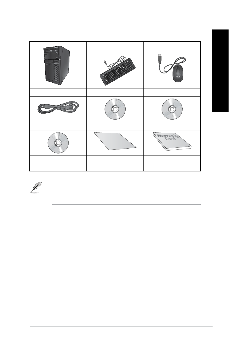
ASUS Desktop PC Keyboard x1 Mouse x1
Power cord x1 Support DVD x1 (Optional) Recovery DVD x1 (Optional)
ENGLISH
Nero 9 burning software
DVD x1 (Optional)
• If any of the above items is damaged or missing, contact your retailer.
• The illustrated items above are for reference only. Actual product specications may vary
with different models.
Installation Guide x1 Warranty card x1
9
Page 12

ENGLISH
10
Page 13

Chapter 1
Getting started
Welcome!
Thank you for purchasing the ASUS Desktop PC!
The ASUS Desktop PC provides cutting-edge performance, uncompromised reliability, and
user-centric utilities. All these values are encapsulated in a stunningly futuristic and stylish
system casing.
Read the ASUS Warranty Card before setting up your ASUS Desktop PC.
Getting to know your computer
Illustrations are for reference only. The ports and their locations, and the chassis color vary
with different models.
ENGLISH
ASUS BM6635(MD560), BM6835, and BP6335(SD560) 11
Page 14
ENGLISH
ENGLISH
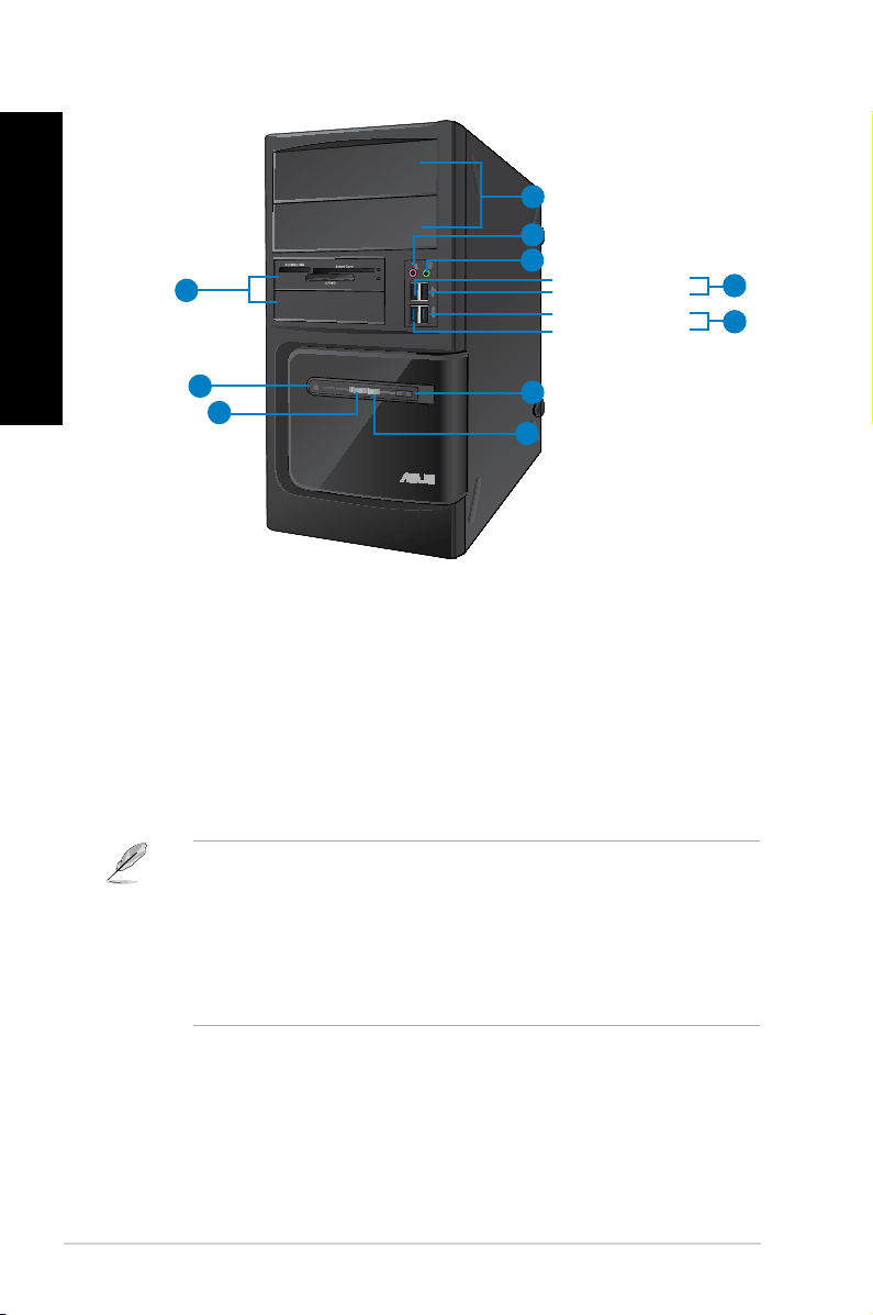
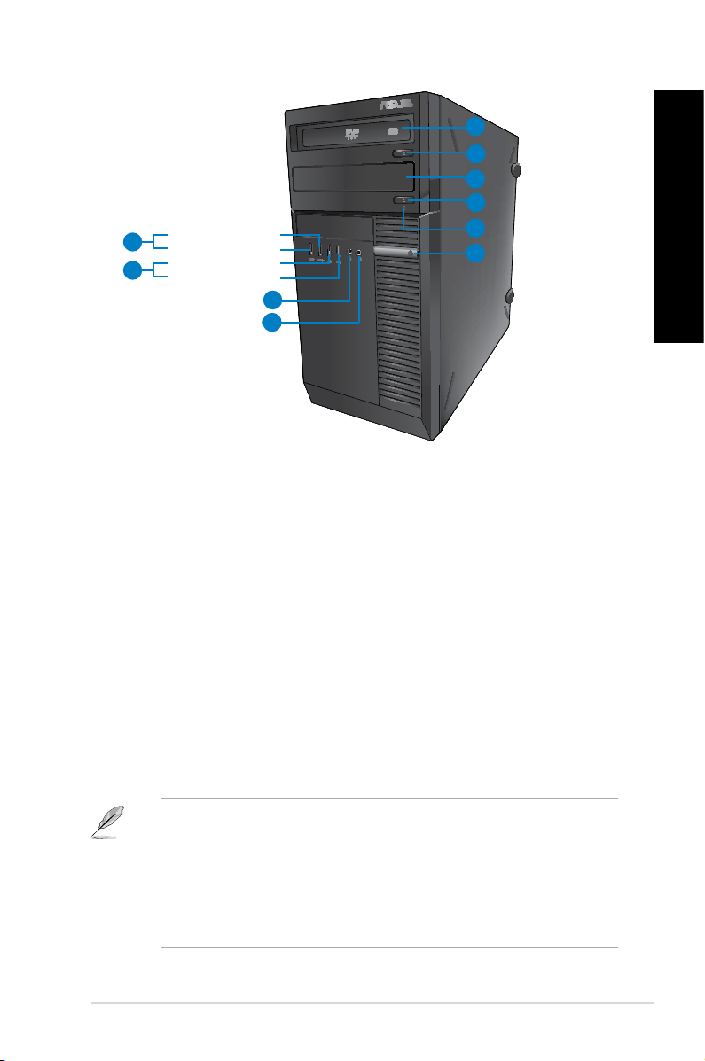
Front panel
10
1
2
3
Front USB 2.0 port 3
Front USB 2.0 port 4
Front USB 3.0 port 1
Front USB 3.0 port 2
4
5
9
6
8
7
BM6635(MD560)
1. 2 x 5.25 inch optical disk drive bays. The 5.25 inch optical disk drive bays are for
5.25 inch DVD-ROM / CD-RW / DVD-RW devices.
2. Microphone port (pink).
3. Headphone port (lime).
4. USB 2.0 ports. These Universal Serial Bus 2.0 (USB 2.0) ports connect to USB 2.0
devices such as a mouse, printer, scanner, camera, PDA, and others.
5. USB 3.0 ports. These Universal Serial Bus 3.0 (USB 3.0) ports connect to USB 3.0
devices such as a mouse, printer, scanner, camera, PDA, and others.
• DO NOT connect a keyboard / mouse to any USB 3.0 port when installing Windows®
operating system.
• Due to USB 3.0 controller limitation, USB 3.0 devices can only be used under Windows
OS environment and after the USB 3.0 driver installation.
• USB 3.0 devices can only be used as data storage only.
• We strongly recommend that you connect USB 3.0 devices to USB 3.0 ports for faster
and better performance for your USB 3.0 devices.
This port connects to a microphone.
This port connects to a headphone or speaker.
®
6. Reset button. Press this button to reboot your computer.
7. HDD LED.
8. Power LED.
9. Power button.
This LED lights up when the hard disk drive operates.
This LED lights up when you turn on your computer.
Press this button to turn on your computer.
10. 2 x 3.5 inch drive bays. The 3.5 inch drive bays are for 3.5 inch hard disk drives /
memory card readers.
12 Chapter 1: Getting started
Page 15
1
ENGLISH
2
3
2
Front USB 3.0 port 1
9
Front USB 3.0 port 2
Front USB 2.0 port 3
8
Front USB 2.0 port 4
4
5
7
6
BM6835
1. 5.25 inch optical disk drive bay. The 5.25 inch optical disk drive bay is for 5.25 inch
DVD-ROM / CD-RW / DVD-RW devices.
2. Optical disk drive eject button.
3. Optical disk drive bay (empty).
bay.
4. HDD LED.
5. Power button.
6. Microphone.
7. Headphone port.
This LED lights up when the hard disk drive operates.
Press this button to turn on your computer.
This port connects to a microphone.
This port connects to a headphone or speaker.
8. USB 2.0 ports. These Universal Serial Bus 2.0 (USB 2.0) ports connect to USB 2.0
devices such as a mouse, printer, scanner, camera, PDA, and others.
9. USB 3.0 ports. These Universal Serial Bus 3.0 (USB 3.0) ports connect to USB 3.0
devices such as a mouse, printer, scanner, camera, PDA, and others.
Press this button to eject the optical disk drive tray.
You may install an additional optical disk drive in this
ENGLISH
• DO NOT connect a keyboard / mouse to any USB 3.0 port when installing Windows®
operating system.
• Due to USB 3.0 controller limitation, USB 3.0 devices can only be used under Windows
OS environment and after the USB 3.0 driver installation.
• USB 3.0 devices can only be used as data storage only.
• We strongly recommend that you connect USB 3.0 devices to USB 3.0 ports for faster
and better performance for your USB 3.0 devices.
ASUS BM6635(MD560), BM6835, and BP6335(SD560) 13
®
Page 16
ENGLISH
ENGLISH
1
2
Front USB 3.0 port 2
4
Front USB 3.0 port 1
Front USB 2.0 port 3
5
Front USB 2.0 port 4
3
8
7
6
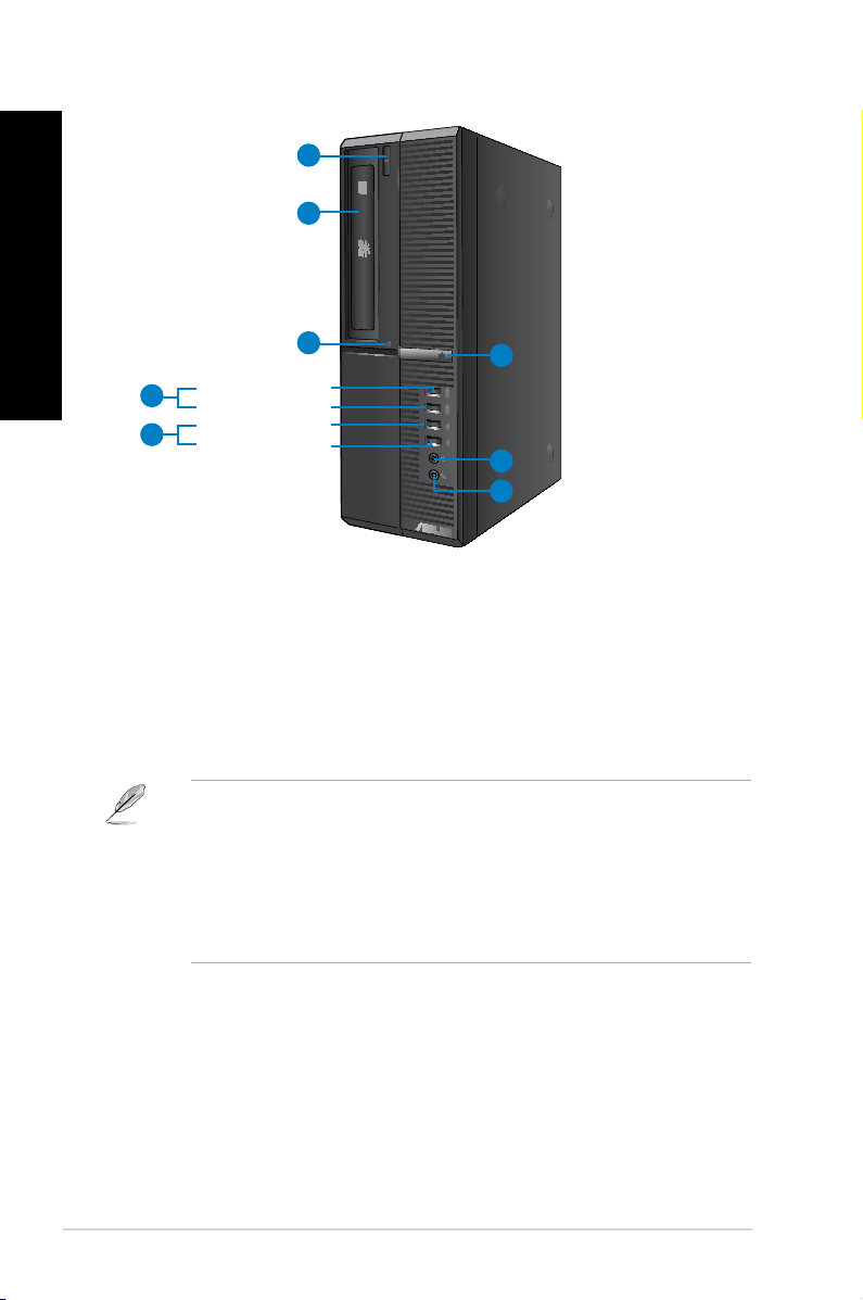
BP6335(SD560)
1. Optical disk drive eject button. Press this button to eject the optical disk drive tray.
2. 5.25 inch optical disk drive bay. The 5.25 inch optical disk drive bay is for 5.25 inch
DVD-ROM / CD-RW / DVD-RW devices.
3. HDD LED.
4. USB 3.0 ports. These Universal Serial Bus 3.0 (USB 3.0) ports connect to USB 3.0
devices such as a mouse, printer, scanner, camera, PDA, and others.
This LED lights up when the hard disk drive operates.
• DO NOT connect a keyboard / mouse to any USB 3.0 port when installing Windows®
operating system.
• Due to USB 3.0 controller limitation, USB 3.0 devices can only be used under Windows
OS environment and after the USB 3.0 driver installation.
• USB 3.0 devices can only be used as data storage only.
• We strongly recommend that you connect USB 3.0 devices to USB 3.0 ports for faster
and better performance for your USB 3.0 devices.
®
5. USB 2.0 ports. These Universal Serial Bus 2.0 (USB 2.0) ports connect to USB 2.0
devices such as a mouse, printer, scanner, camera, PDA, and others.
6. Microphone.
7. Headphone port.
8. Power button.
14 Chapter 1: Getting started
This port connects to a microphone.
This port connects to a headphone or speaker.
Press this button to turn on your computer.
Page 17
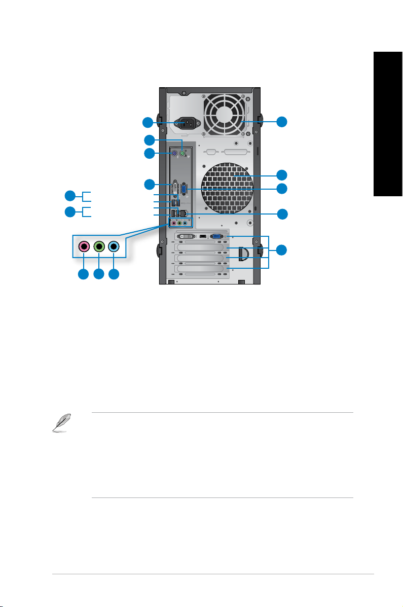
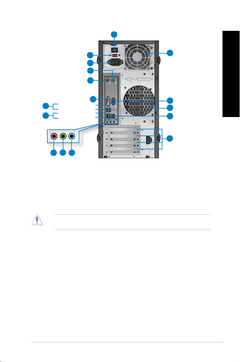
Rear panel
ENGLISH
1
13
2
3
13
Rear USB 3.0 port 2
5
Rear USB 3.0 port 1
Rear USB 2.0 port 3
6
Rear USB 2.0 port 4
4
12
11
10
8
7
9
BM6635(MD560)
1. Power connector.Power connector. Plug the power cord to this connector.
2. PS/2 mouse port (green). This port is for a PS/2 mouse.
3. PS/2 keyboard port (purple). This port is for a PS/2 keyboard.
4. DVI-D port.DVI-D port.
allowing playback of HD DVD, Blu-ray, and other protected content.
5. USB 3.0 ports. These Universal Serial Bus 3.0 (USB 3.0) ports connect to USB 3.0
devices such as a mouse, printer, scanner, camera, PDA, and others.
This port is for any DVI-D compatible device and is HDCP compliant
ENGLISH
• DO NOT connect a keyboard / mouse to any USB 3.0 port when installing Windows®
operating system.
• Due to USB 3.0 controller limitation, USB 3.0 devices can only be used under Windows
OS environment and after the USB 3.0 driver installation.
• USB 3.0 devices can only be used as data storage only.
• We strongly recommend that you connect USB 3.0 devices to USB 3.0 ports for faster
and better performance for your USB 3.0 devices.
®
6. USB 2.0 ports. These Universal Serial Bus 2.0 (USB 2.0) ports connect to USB 2.0
devices such as a mouse, printer, scanner, camera, PDA, and others.
ASUS BM6635(MD560), BM6835, and BP6335(SD560) 15
Page 18
ENGLISH
ENGLISH
7. Microphone port (pink).Microphone port (pink). This port connects to a microphone.
8. Line Out port (lime).Line Out port (lime).
This port connects to a headphone or speaker. In a 4, 6, or
8-channel conguration, the function of this port becomes Front Speaker Out.
9. Line In port (light blue).Line In port (light blue).
This port connects to a tape, CD, DVD player, or other audio
sources.
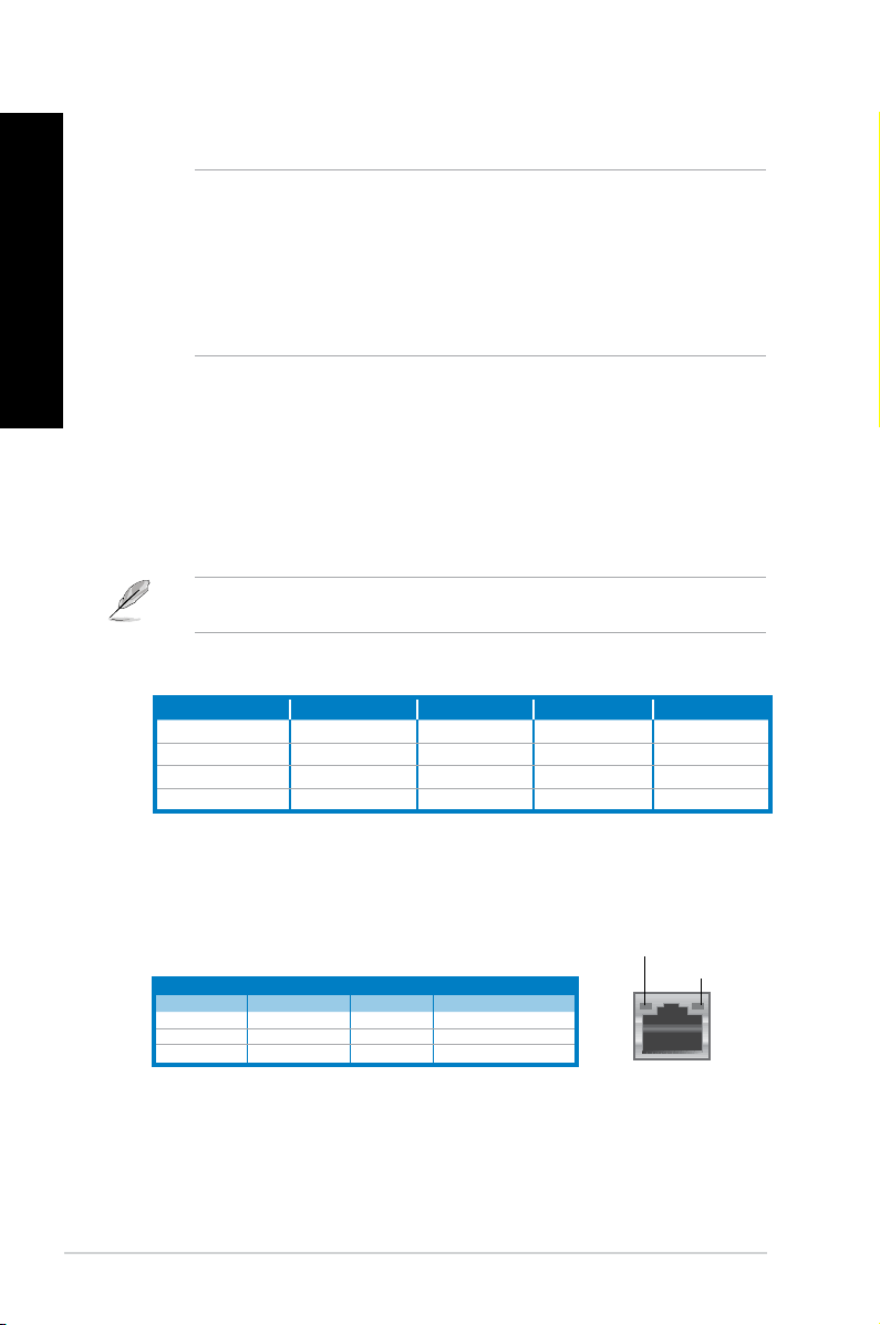
Refer to the audio conguration table below for the function of the audio ports in the 2, 4, 6,
or 8-channel conguration.
Audio 2, 4, 6, or 8-channel conguration
Port Headset 2-channel 4-channel 6-channel 8-channel
Light Blue (Rear panel) Line In Rear Speaker Out Rear Speaker Out Rear Speaker Out
Lime (Rear panel) Line Out Front Speaker Out Front Speaker Out Front Speaker Out
Pink (Rear panel) Mic In Mic In Bass/Center Bass/Center
Lime (Front panel) - - - Side Speaker Out
10. Expansion slot brackets.Expansion slot brackets. Remove the expansion slot bracket when installing an
expansion card.
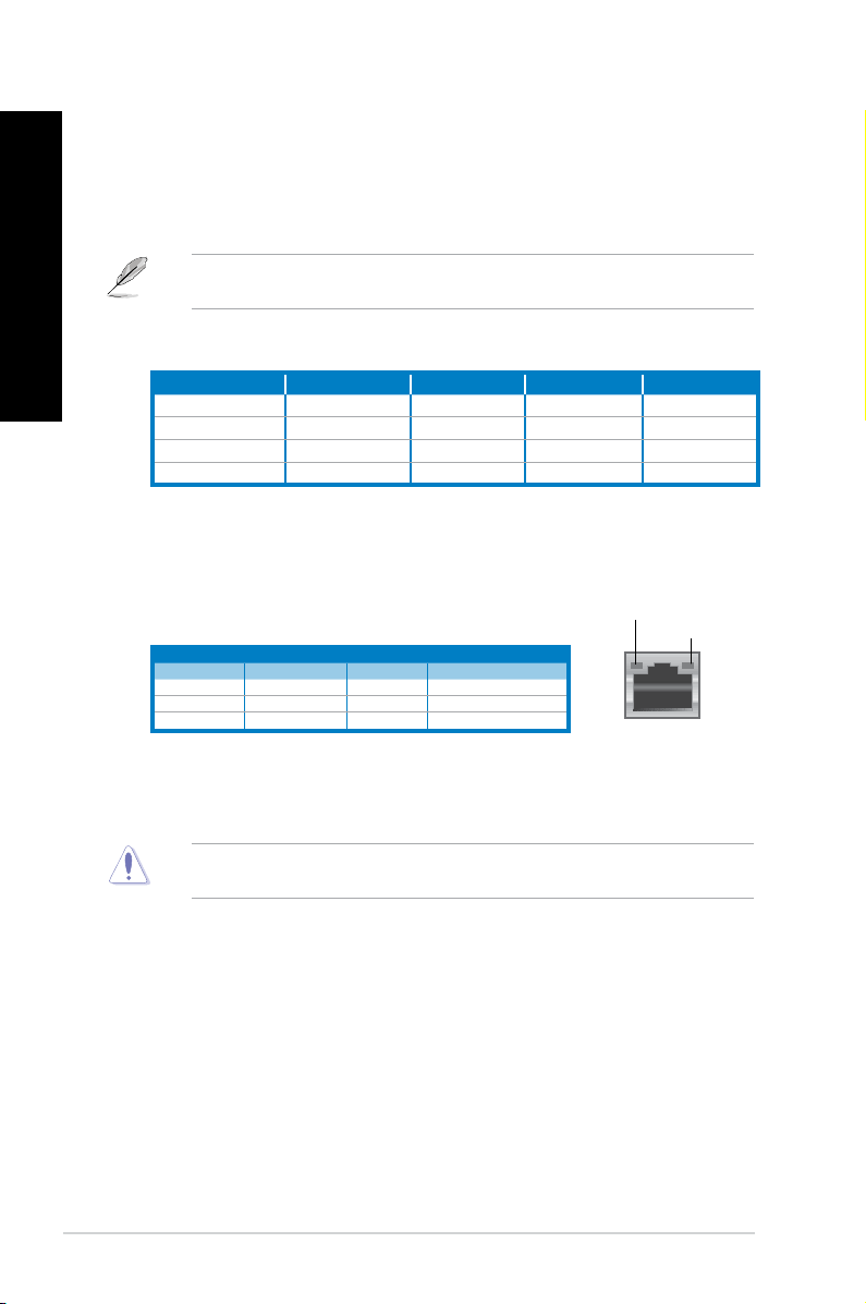
11. LAN (RJ-45) port.LAN (RJ-45) port.
This port allows Gigabit connection to a Local Area Network (LAN)
through a network hub.
LAN port LED indications
Activity/Link LED Speed LED
Status Description Status Description
OFF No link OFF 10Mbps connection
ORANGE Linked ORANGE 100Mbps connection
BLINKING Data activity GREEN 1Gbps connection
ACT/LINK LED
SPEED LED
LAN port
12. VGA port.VGA port. This port is for VGA-compatible devices such as a VGA monitor.
13. Air vents.Air vents.
16 Chapter 1: Getting started
These vents allow air ventilation.
DO NOT block the air vents on the chassis. Always provide proper ventilation for your
computer.
Page 19
1
ENGLISH
14
15
14
13
12
Rear USB 3.0 port 2
7
Rear USB 3.0 port 1
Rear USB 2.0 port 3
8
Rear USB 2.0 port 4
10
9
2
3
4
5
6
11
BM6835
1. Power switch. Switch to turn ON/OFF the power supply to your computer.
2 . Voltage selector.
according to the voltage supply in your area. If the voltage supply in your area is 100127V, set the switch to 115V. If the voltage supply in your area is 200-240V, set the
switch to 230V.
Setting the switch to 115V in a 230V environment or 230V in a 115V environment will
seriously damage the system!
Use this switch to select the appropriate system input voltage
ENGLISH
3. Power connector.Power connector. Plug the power cord to this connector.
4. PS/2 mouse port (green). This port is for a PS/2 mouse.
5. PS/2 keyboard port (purple). This port is for a PS/2 keyboard.
6. DVI-D port.DVI-D port.
allowing playback of HD DVD, Blu-ray, and other protected content.
ASUS BM6635(MD560), BM6835, and BP6335(SD560) 17
This port is for any DVI-D compatible device and is HDCP compliant
Page 20
ENGLISH
ENGLISH
7. USB 3.0 ports. These Universal Serial Bus 3.0 (USB 3.0) ports connect to USB 3.0
devices such as a mouse, printer, scanner, camera, PDA, and others.
• DO NOT connect a keyboard / mouse to any USB 3.0 port when installing Windows®
operating system.
• Due to USB 3.0 controller limitation, USB 3.0 devices can only be used under Windows
OS environment and after the USB 3.0 driver installation.
• USB 3.0 devices can only be used as data storage only.
• We strongly recommend that you connect USB 3.0 devices to USB 3.0 ports for faster
and better performance for your USB 3.0 devices.
8. USB 2.0 ports.USB 2.0 ports. These Universal Serial Bus 2.0 (USB 2.0) ports connect to USB 2.0
devices such as a mouse, printer, scanner, camera, PDA, and others.
9. Microphone port (pink).Microphone port (pink).
10. Line Out port (lime).Line Out port (lime).
This port connects to a microphone.
This port connects to a headphone or speaker. In a 4, 6, or
8-channel conguration, the function of this port becomes Front Speaker Out.
11. Line In port (light blue).Line In port (light blue).
This port connects to a tape, CD, DVD player, or other audio
sources.
Refer to the audio conguration table below for the function of the audio ports in the 2, 4, 6,
or 8-channel conguration.
Audio 2, 4, 6, or 8-channel conguration
Port Headset 2-channel 4-channel 6-channel 8-channel
Light Blue (Rear panel) Line In Rear Speaker Out Rear Speaker Out Rear Speaker Out
Lime (Rear panel) Line Out Front Speaker Out Front Speaker Out Front Speaker Out
Pink (Rear panel) Mic In Mic In Bass/Center Bass/Center
Lime (Front panel) - - - Side Speaker Out
®
12. Expansion slot brackets.Expansion slot brackets. Remove the expansion slot bracket when installing an
expansion card.
13. LAN (RJ-45) port.LAN (RJ-45) port.
This port allows Gigabit connection to a Local Area Network (LAN)
through a network hub.
LAN port LED indications
Activity/Link LED Speed LED
Status Description Status Description
OFF No link OFF 10Mbps connection
ORANGE Linked ORANGE 100Mbps connection
BLINKING Data activity GREEN 1Gbps connection
18 Chapter 1: Getting started
ACT/LINK LED
SPEED LED
LAN port
Page 21
14. Air vents.Air vents. These vents allow air ventilation.
ENGLISH
DO NOT block the air vents on the chassis. Always provide proper ventilation for your
computer.
15. VGA port.VGA port. This port is for VGA-compatible devices such as a VGA monitor.
1
2
Rear USB 3.0 port 2
4
Rear USB 3.0 port 1
Rear USB 2.0 port 3
5
Rear USB 2.0 port 4
3
14
11
13
6 7 8
9
10
12
11
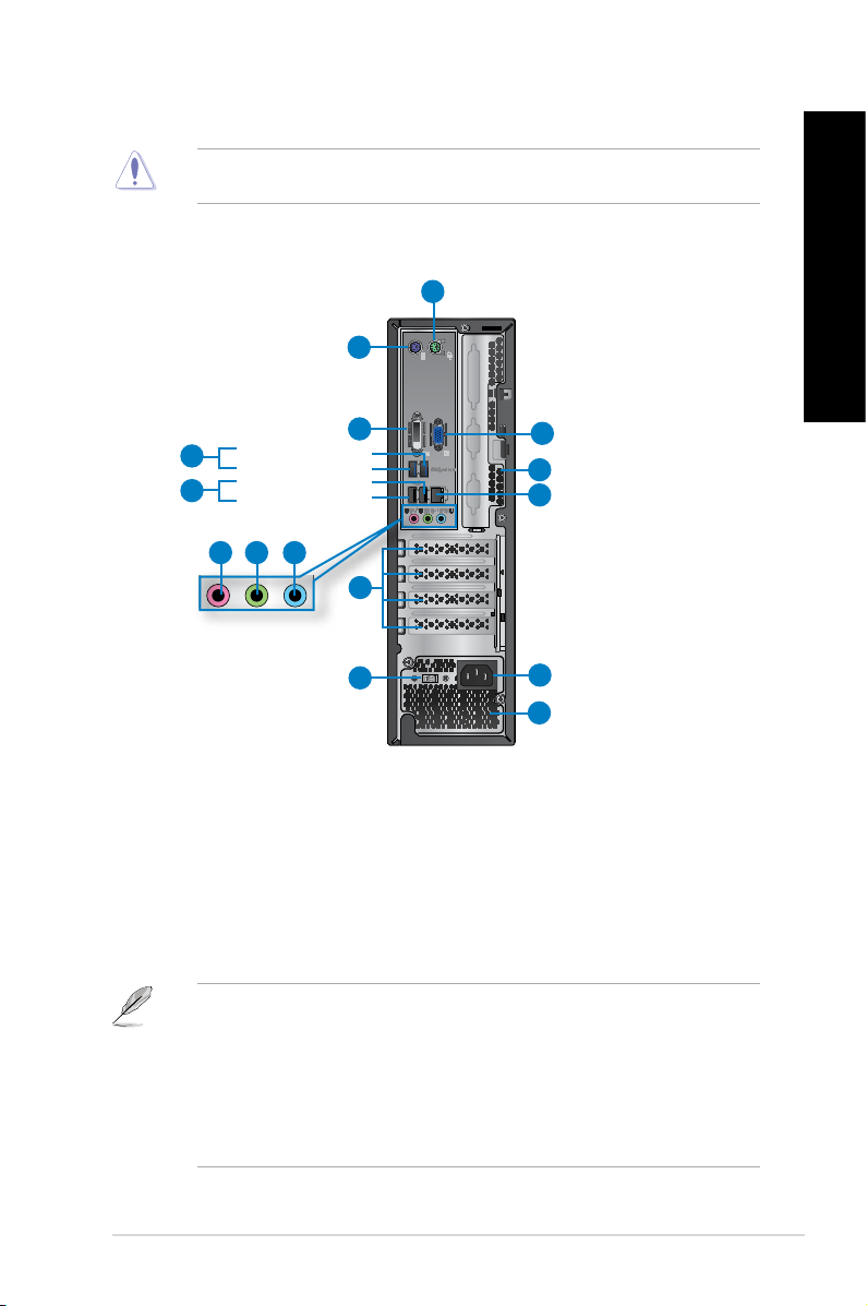
BP6335(SD560)
1. PS/2 mouse port (green). This port is for a PS/2 mouse.
2. PS/2 keyboard port (purple). This port is for a PS/2 keyboard.
3. DVI-D port.DVI-D port.
allowing playback of HD DVD, Blu-ray, and other protected content.
4. USB 3.0 ports. These Universal Serial Bus 3.0 (USB 3.0) ports connect to USB 3.0
devices such as a mouse, printer, scanner, camera, PDA, and others.
This port is for any DVI-D compatible device and is HDCP compliant
ENGLISH
• DO NOT connect a keyboard / mouse to any USB 3.0 port when installing Windows®
operating system.
• Due to USB 3.0 controller limitation, USB 3.0 devices can only be used under Windows
OS environment and after the USB 3.0 driver installation.
• USB 3.0 devices can only be used as data storage only.
• We strongly recommend that you connect USB 3.0 devices to USB 3.0 ports for faster
and better performance for your USB 3.0 devices.
ASUS BM6635(MD560), BM6835, and BP6335(SD560) 19
®
Page 22
ENGLISH
ENGLISH
5. USB 2.0 ports.USB 2.0 ports. These Universal Serial Bus 2.0 (USB 2.0) ports connect to USB 2.0
devices such as a mouse, printer, scanner, camera, PDA, and others.
6. Microphone port (pink).Microphone port (pink).
7. Line Out port (lime).Line Out port (lime).
This port connects to a microphone.
This port connects to a headphone or speaker. In a 4, 6, or
8-channel conguration, the function of this port becomes Front Speaker Out.
8. Line In port (light blue).Line In port (light blue).
This port connects to a tape, CD, DVD player, or other audio
sources.
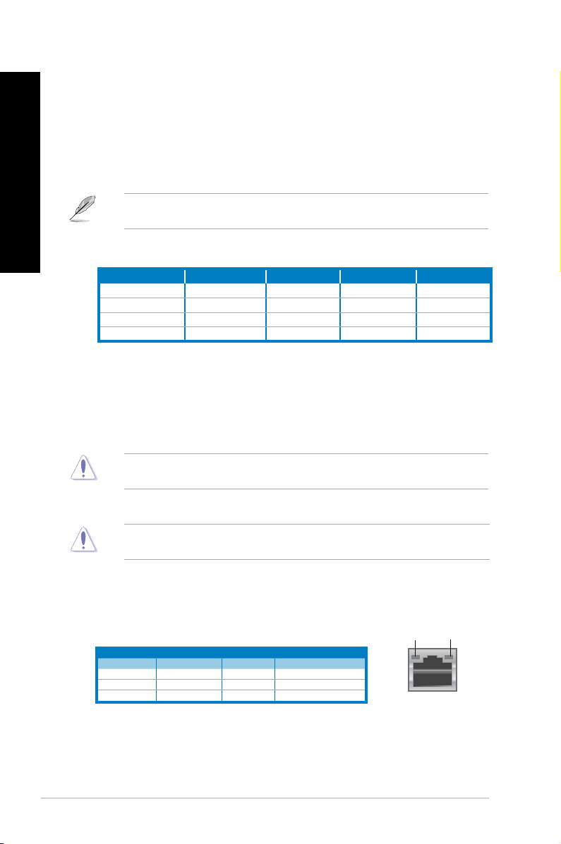
Refer to the audio conguration table below for the function of the audio ports in the 2, 4, 6,
or 8-channel conguration.
Audio 2, 4, 6, or 8-channel conguration
Port Headset 2-channel 4-channel 6-channel 8-channel
Light Blue (Rear panel) Line In Rear Speaker Out Rear Speaker Out Rear Speaker Out
Lime (Rear panel) Line Out Front Speaker Out Front Speaker Out Front Speaker Out
Pink (Rear panel) Mic In Mic In Bass/Center Bass/Center
Lime (Front panel) - - - Side Speaker Out
9. Expansion slot brackets.Expansion slot brackets. Remove the expansion slot bracket when installing an
expansion card.
10. Voltage selector.
Use this switch to select the appropriate system input voltage
according to the voltage supply in your area. If the voltage supply in your area is 100127V, set the switch to 115V. If the voltage supply in your area is 200-240V, set the
switch to 230V.
Setting the switch to 115V in a 230V environment or 230V in a 115V environment will
seriously damage the system!
11. Air vents. These vents allow air ventilation.
DO NOT block the air vents on the chassis. Always provide proper ventilation for your
computer.
12. Power connector.Power connector. Plug the power cord to this connector.
13. LAN (RJ-45) port.LAN (RJ-45) port.
through a network hub.
LAN port LED indications
Activity/Link LED Speed LED
Status Description Status Description
OFF No link OFF 10Mbps connection
ORANGE Linked ORANGE 100Mbps connection
BLINKING Data activity GREEN 1Gbps connection
This port allows Gigabit connection to a Local Area Network (LAN)
ACT/LINK
LED
SPEED
LED
LAN port
14. VGA port.VGA port. This port is for VGA-compatible devices such as a VGA monitor.
20 Chapter 1: Getting started
Page 23
Setting up your computer
ENGLISH
This section guides you through connecting the main hardware devices, such as the external
monitor, keyboard, mouse, and power cord, to your computer.
Using the onboard display output ports
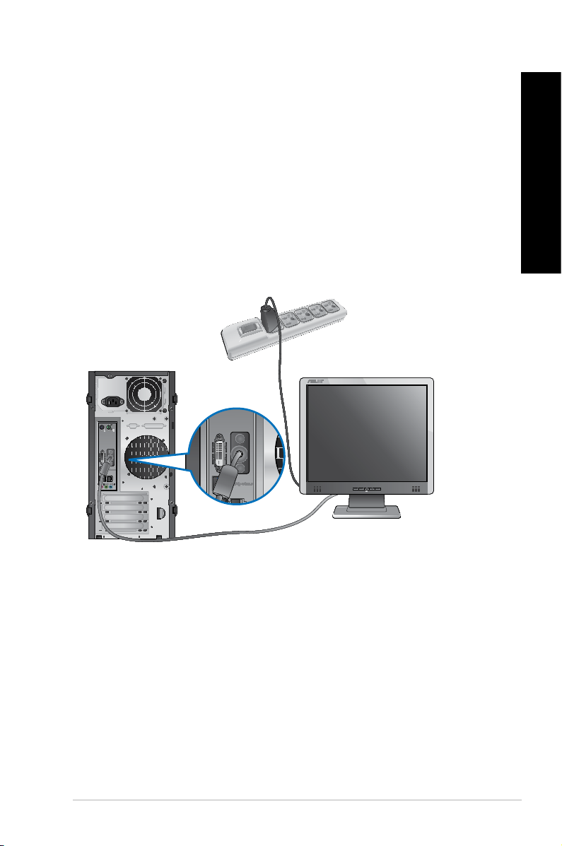
Connect your monitor to the onboard display output port.
To connect an external monitor using the onboard display output ports:
1. Connect your monitor to the VGA port, DVI-D port, or display port of your computer.
2. Plug your monitor to a power source.
BM6635(MD560)
ENGLISH
ASUS BM6635(MD560), BM6835, and BP6335(SD560) 21
Page 24
ENGLISH
ENGLISH
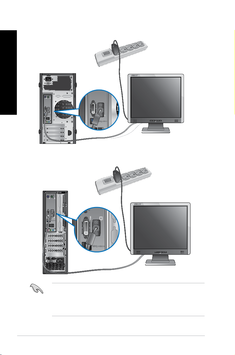
BM6835
BP6335(SD560)
• If your computer comes with an ASUS Graphics Card, the graphics card is set as the
primary display device in the BIOS. Hence, connect your monitor to a display output port
on the graphics card.
• To connect multiple external monitors to your computer, refer to Connecting multiple
external monitors in Chapter 3 of this user manual for details.
22 Chapter 1: Getting started
Page 25
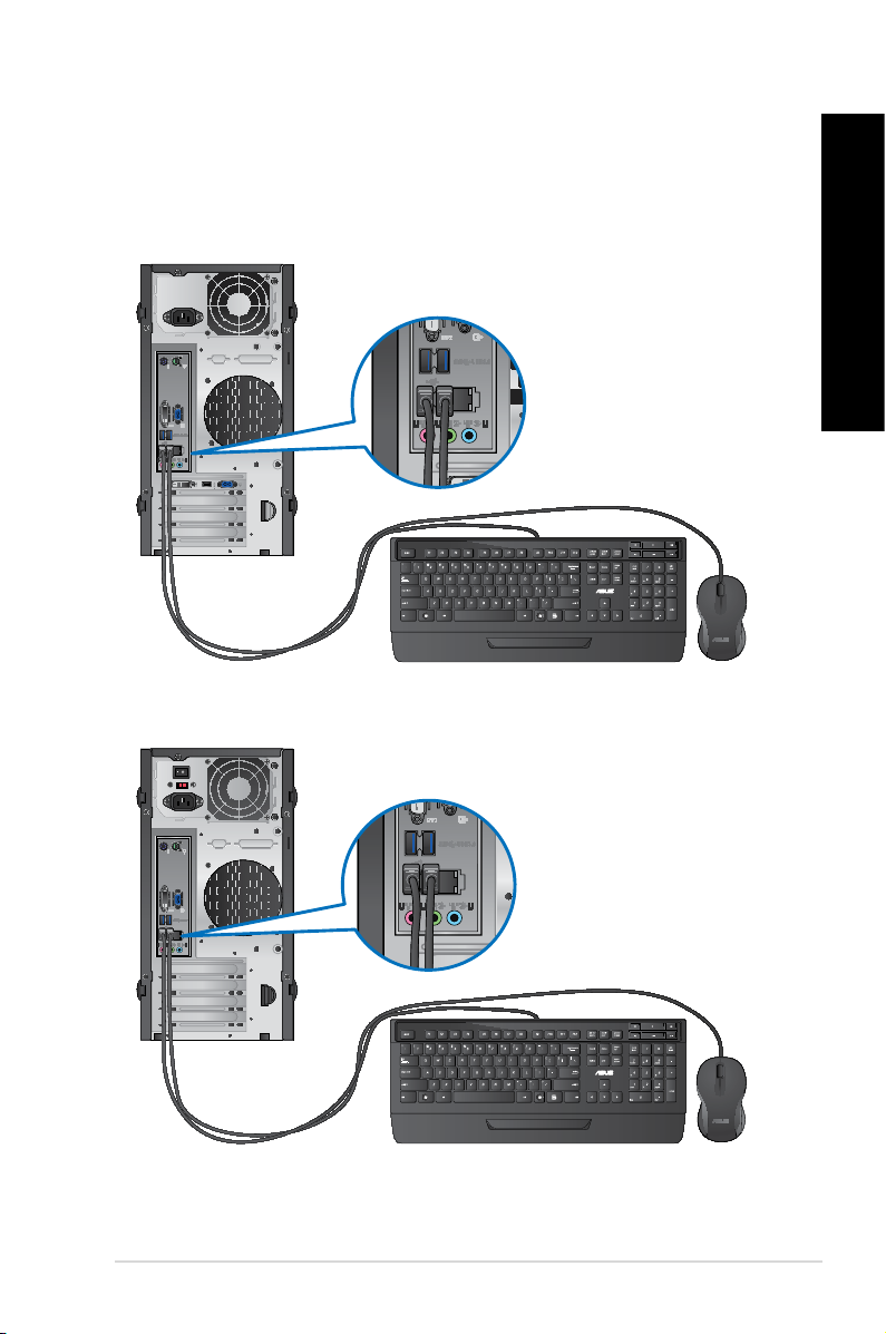
Connecting a USB keyboard and a USB mouse
ENGLISH
Connect a USB keyboard and a USB mouse to the USB ports on the rear panel of your
computer.
BM6635(MD560)
BM6835
ENGLISH
ASUS BM6635(MD560), BM6835, and BP6335(SD560) 23
Page 26
ENGLISH
ENGLISH
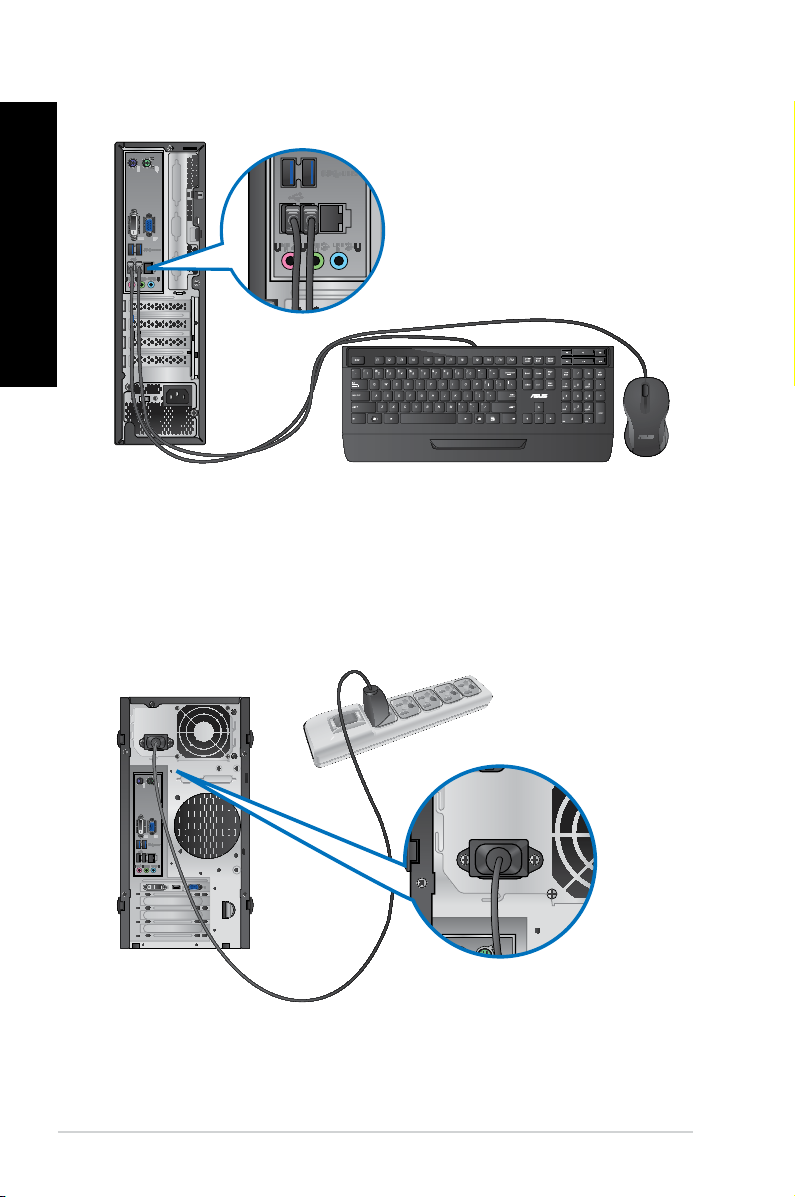
BP6335(SD560)
Connecting the power cord
Connect one end of the power cord to the power connector on the rear panel of your
computer and the other end to a power source.
BM6635(MD560)
24 Chapter 1: Getting started
Page 27
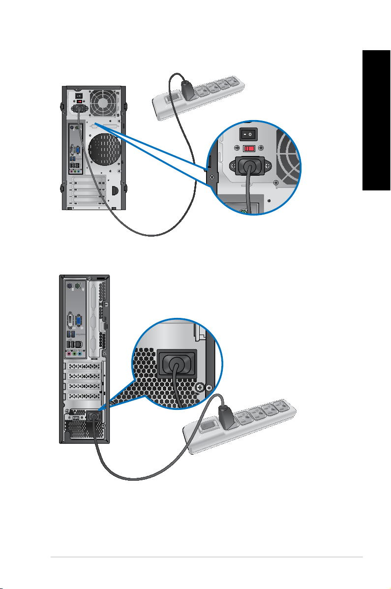
BM6835
ENGLISH
BP6335(SD560)
ENGLISH
ASUS BM6635(MD560), BM6835, and BP6335(SD560) 25
Page 28
ENGLISH
Turning your computer ON/OFF
This section describes how to turn on/off your computer after setting up your computer.
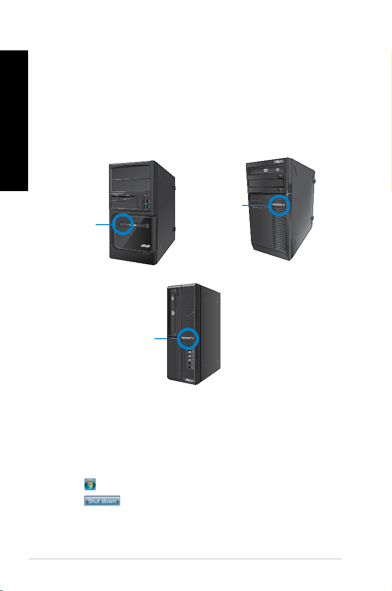
Turning your computer ON
To turn your computer ON:
1. Turn your monitor ON.
2. Turn the power switch ON (for BM6835 only).
3. Press the power button on your computer.
Power button
Power button
BM6635(MD560)
Power button
BP6335(SD560)
4. Wait until the operating system loads automatically.
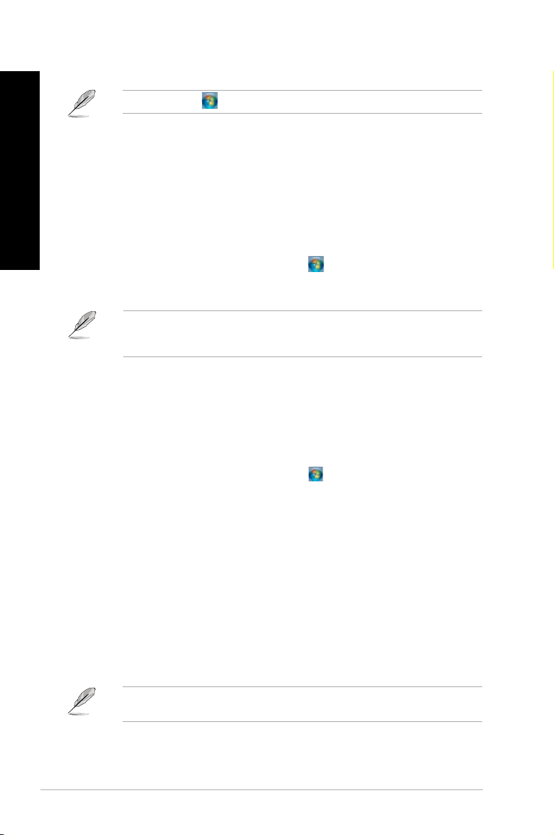
Turning your computer OFF
To turn your computer OFF:
1. Close all running applications.
2. Click
3. Click
on the Windows® desktop.
to shut down the operating system.
BM6835
26 Chapter 1: Getting started
Page 29

Chapter 2
Using Windows® 7
Starting for the rst time
When you start your computer for the rst time, a series of screens appear to guide you in
conguring the basic settings of your Windows® 7 operating system.
To start for the rst time:
1. Turn your computer on. Wait for a few minutes until the Set Up Windows
appears.
2. From dropdown list, select your language, then click
3. From the dropdown lists, select your Country or region
Keyboard layout, then click Next.
4. Key in uniques names for the user name
5. Key in the necessary information to set up your password, then click
also click Next to skip this step without entering any information.
If you want to set up a password for your account later, refer to the section Setting up a
user account and password in this chapter.
6. Carefully read the license terms. Tick I accept the license terms
7. Select Use recommended settings
security settings for your computer. To skip this step, select Ask me later.
8. Review your date and time settings. Click
restarts. You may now start using your computer.
and computer name, then click Next.
or Install important updates only to set up the
Next. The system loads the new settings and
Next.
, Time and currency, and
screen
Next. You may
and click Next.
ENGLISH
ASUS BM6635(MD560), BM6835, and BP6335(SD560) 27
Page 30
ENGLISH
Using Windows® 7 desktop
ENGLISH
Click the Start icon > Help and Support to obtain more information about Windows® 7.
Using the Start menu
The Start menu gives you access to programs, utilities, and other useful items on your
computer. It also provides you with more information about Windows 7 through its Help and
Support feature.
Launching items from the Start menu
To launch items from the Start menu:
®
1. From the Windows
2. From the Start menu, select the item that you want to launch.
You may pin programs that you want constantly displayed on the Start menu. For more
details, refer to the section Pinning programs on the Start menu or taskbar on this
chapter.
Using the Getting Started item
The Getting Started item on the Start menu contains information about some basic tasks
such as personalizing Windows®, adding new users, and transferring les to help you to
familiarize yourself with using Windows® 7.
To use the Getting Started item:
1. From the Windows
2. Select Getting Started
3. Select the task that you want to do.
taskbar, click the Start icon .
®
taskbar, click the Start icon to launch the Start menu.
. The list of available tasks appears.
Using the taskbar
The taskbar allows you to launch and manage programs or items installed on your computer.
Launching a program from the taskbar
To launch a program from the taskbar:
®
• From the Windows
program.
You may pin programs that you want constantly displayed on the taskbar. For more details,
refer to the section Pinning programs on the Start menu or taskbar on this chapter.
28 Chapter 2: Using Windows® 7
taskbar, click an icon to launch it. Click the icon again to hide the
Page 31

ENGLISH
Pinning items on the jumplists
When you right-click an icon on the taskbar, a jumplist launches to provide you with quickaccess to the program’s or item’s related links.You may pin items on the jumplist such as
favorite websites, often-visited folders or drives, or recently played media les.
To pin items to the jumplist:
1. From the taskbar, right-click an icon.
2. From the jumplist, right-click the item that you want to pin, then select Pin to this list
Unpinning items from the jumplist
To unpin items from the jumplist:
1. From the taskbar, right-click an icon.
2. From the jumplist, right-click the item that you want to remove from the jumplist, then
select Unpin from this list.
Pinning programs on the Start menu or taskbar
To pin programs on the Start menu or taskbar:
®
1. From the Windows
2. Right-click the item that you want to pin on the Start menu or taskbar.
3. Select Pin to Taskbar
You may also right-click on the icon of a running program on the taskbar, then select Pin
this program to taskbar.
taskbar, click the Start icon to launch the Start menu.
or Pin to Start menu.
ENGLISH
.
Unpinning programs from the Start menu
To unpin programs from the Start menu:
®
1. From the Windows
2. From the Start menu, right-click the program that you want to unpin, then select
Remove from this list
taskbar, click the Start icon to launch the Start menu.
.
Unpinning programs from the taskbar
To unpin programs from the taskbar:
1. From the taskbar, right-click the program that you want to remove from the taskbar,
then select Unpin this program from taskbar.
ASUS BM6635(MD560), BM6835, and BP6335(SD560) 29
Page 32

ENGLISH
ENGLISH
Using the notication area
By default, the notication area shows these three icons:
Action Center notication
Click this icon to display all the alert messages/notications and launch the Windows®
Action Center.
Network connection
This icon displays the connection status and signal strength of the wired or wireless network
connection.
Volume
Click this icon to adjust the volume.
Displaying an alert notication
To display an alert notication:
• Click the Notication icon
For more details, refer to the section Using Windows® Action Center in this chapter.
, then click the message to open it.
Customizing icons and notications
You may choose to display or hide the icons and notications on the taskbar or on the
notication area.
To customize icons and notications:
1. From the notication area, click on the arrow icon
2. Click
3. From the dropdown list, select the behaviors for the icons or items that you want to
Customize.
customize.
.
Managing your les and folders
Using Windows® Explorer
Windows® Explorer allows you to view, manage, and organize your les and folders.
Launching Windows® Explorer
To launch Windows Explorer:
®
1. From the Windows
2. Click
Computer to launch Windows Explorer.
taskbar, click the Start icon to launch the Start menu.
30 Chapter 2: Using Windows® 7
Page 33

ENGLISH
Exploring les and folders
To explore les and folders:
®
1. Launch Windows
2. From the navigation or view pane, browse for the location of your data.
3. From the breadcrumb bar, click the arrow to display the contents of the drive or folder.
Explorer.
Customizing the le/folder view
To customize the le/folder view:
1. Launch Windows Explorer.
2. From the navigation pane, select the location of your data.
3. From the toolbar, click the View icon
4. From the View menu, move the slider to select how you want to view the le/folder.
You may also right-click anywhere on the View pane, click View, and select the view type
that you want.
.
Arranging your les
To arrange your les:
1. Launch Windows Explorer.
2. From the Arrange by
3. Select your preferred arrangement type.
eld, click to display the dropdown list.
ENGLISH
Sorting your les
To sort your les:
1. Launch Windows Explorer.
2. Right-click anywhere on the View pane.
3. From the menu that appears, select Sort by
, then select your preferred sorting type.
Grouping your les
To group your les:
1. Launch Windows Explorer.
2. Right-click anywhere on the View pane.
3. From the menu that appears, select Group by
type.
ASUS BM6635(MD560), BM6835, and BP6335(SD560) 31
, then select your preferred grouping
Page 34

ENGLISH
ENGLISH
Adding a new folder
To add a new folder:
1. Launch Windows Explorer.
2. From the toolbar, click New folder
3. Key in a name for the new folder.
You may also right-click anywhere on the View pane, click New > Folder.
Backing up your les
Setting up a backup
To set up a backup:
.
1. Click
2. Click Set up backup
3. Select your backup destination. Click
4. Select Let Windows choose (recommended)
5. Follow the onscreen instructions to nish the process.
> All Programs > Maintenance > Backup and Restore.
. Click Next.
Next.
or Let me choose as your backup
mode.
If you select Let Windows choose, Windows will not back up your programs, FAT-
formatted les, Recycle Bin les, or temporary les that are 1GB or more.
Restoring your system settings
The Windows® System Restore feature creates a restore point where the computer’s system
settings are stored at certain time and date. It allows you to restore or undo changes to your
computer’s system settings without affecting your personal data.
To restore your system:
1. Close all running applications.
2. Click
3. Follow the onscreen instructions to complete the process.
> All Programs > Accessories > System Tools > System Restore.
32 Chapter 2: Using Windows® 7
Page 35

ENGLISH
Protecting your computer
Using Windows® 7 Action Center
Windows® 7 Action Center provides you with alert notications, security information, system
maintenance information, and the option to automatically troubleshoot and x some common
computer problems.
You may customize the notications. For more details, refer to the previous section
Customizing icons and notications in this chapter.
Launching Windows® 7 Action Center
To launch Windows® 7 Action Center:
ENGLISH
1. To launch Windows 7 Action Center, click the Notication icon
Action Center.
2. From Windows 7 Action Center, click the task that you want to do.
, then click Open
Using Windows® Update
Windows Update allows you to check and install the latest updates to enhance the security
and performance of your computer.
Launching Windows® Update
To launch Windows® Update:
®
1. From the Windows
2. Select All Programs
3. From the Windows Update screen, click the task that you want to do.
taskbar, click the Start icon to launch the Start menu.
> Windows Update.
Setting up a user account and password
You may create user accounts and passwords for people who will use your computer.
Setting up a user account
To set up a user account:
®
1. From the Windows
2. Select Manage another account
3. Select Create a new account
4. Key in the name of the new user.
5. Select either Standard user
6. When done, click Create Account
taskbar, click > Getting Started > Add new users.
.
.
or Administrator as the user type.
.
ASUS BM6635(MD560), BM6835, and BP6335(SD560) 33
Page 36

ENGLISH
Setting up a user’s password
To set up a user’s password:
1. Select the user that you would like to set a password.
2. Select Create a password
3. Key in a password and conrm it. Key in your password’s hint.
4. When done, click Create password
.
.
Activating the anti-virus software
Trend Micro Internet Security is pre-installed on your computer. It is a third-party anti-virus
software protecting your computer from virus. It is purchased separately. You have a 30-day
trial period after activating it.
To activate Trend Micro Internet Security:
1. Run the Trend Micro Internet Security application.
2. Carefully read the license terms. Click Agree & Activate
3. Input your e-mail address and select your location. Click
4. Click Finish to complete the activation.
.
Next.
Getting Windows® Help and Support
Windows® Help and Support provides you with guides and answers in using the applications
in Windows® 7 platform.
To launch Windows® Help and Support, click > Help and Support.
Ensure that you are connected to the Internet to obtain the latest Windows
34 Chapter 2: Using Windows® 7
®
online help.
Page 37

Chapter 3
Connecting devices to your computer
Connecting a USB storage device
This desktop PC provides USB 2.0/1.1 and USB 3.0 ports on both the front and rear panels.
The USB ports allow you to connect USB devices such as storage devices.
To connect a USB storage device:
• Insert the USB storage device to your computer.
You can enable or disable the front and rear USB 2.0 and USB 3.0 ports individually from
the BIOS Setup. Refer to the Conguring the USB ports using the BIOS section in
Chapter 6 of this user manual for details.
Front panel
BM6835BM6635(MD560)
ENGLISH
BP6335(SD560)
ASUS BM6635(MD560), BM6835, and BP6335(SD560) 35
Page 38

ENGLISH
ENGLISH
Rear panel
BM6635(MD560)
BM6835
BP6335(SD560)
36 Chapter 3: Connecting devices to your computer
Page 39

Connecting microphone and speakers
ENGLISH
This desktop PC comes with microphone ports and speaker ports on both the front and
rear panels. The audio I/O ports located on the rear panel allow you to connect 2-channel,
4-channel, 6-channel, and 8-channel stereo speakers.
Connecting Headphone and Mic
BM6635(MD560)
BM6835
ENGLISH
ASUS BM6635(MD560), BM6835, and BP6335(SD560) 37
Page 40

LINE OUT
ENGLISH
ENGLISH
BP6335(SD560)
Connecting 2-channel Speakers
38 Chapter 3: Connecting devices to your computer
Page 41

Connecting 4-channel Speakers
LINE OUT
LINE OUT
ENGLISH
Connecting 6-channel Speakers
ENGLISH
ASUS BM6635(MD560), BM6835, and BP6335(SD560) 39
Page 42

LINE OUT
ENGLISH
Connecting 8-channel Speakers
40 Chapter 3: Connecting devices to your computer
Page 43

Chapter 4
Eye level to the top of
the monitor screen
Foot rest 90˚ angles
Using your computer
Proper posture when using your Desktop PC
When using your Desktop PC, maintaining the proper posture is necessary to prevent strain to
your wrists, hands, and other joints or muscles. This section provides you with tips on avoiding
physical discomfort and possible injury while using and fully enjoying your Desktop PC.
To maintain the proper posture:
• Position your computer chair to make sure that your elbows are at or slightly above the
keyboard to get a comfortable typing position.
• Adjust the height of your chair to make sure that your knees are slightly higher than
your hips to relax the backs of your thighs. If necessary, use a footrest to raise the level
of your knees.
• Adjust the back of your chair so that the base of your spine is rmly supported and
angled slightly backward.
• Sit upright with your knees, elbows and hips at an approximately 90º angle when you
are at the PC.
• Place the monitor directly in front of you, and turn the top of the monitor screen even
with your eye level so that your eyes look slightly downward.
• Keep the mouse close to the keyboard, and if necessary, use a wrist rest for support to
reduce the pressure on your wrists while typing.
• Use your Desktop PC in a comfortably-lit area, and keep it away from sources of glare
such as windows and straight sunlight.
• Take regular mini-breaks from using your Desktop PC.
ENGLISH
ASUS BM6635(MD560), BM6835, and BP6335(SD560) 41
Page 44

ENGLISH
ENGLISH
Using the optical drive (on selected models only)
2
1
3
Inserting an optical disc
To insert an optical disc:
1. While your system is on, press the eject button below the drive bay cover to open the
tray.
2. Place the disc to the optical drive with the label side facing up.
3. Push the tray to close it.
4. Select a program from the AutoPlay window to access your les.
If AutoPlay is NOT enabled in your computer, click Windows® 7 Start button on the taskbar,
click Computer, and then double-click the CD/DVD drive icon to access the data on it.
Removing an optical disc
To remove an optical disc:
1. While the system is on, do either of the following to eject the tray:
• Press the eject button below the drive bay cover.
• Right-click the CD/DVD drive icon on the
2. Remove the disc from the disc tray.
Computer screen, and then click Eject.
42 Chapter 4: Using your computer
Page 45

Conguring the USB ports using the BIOS
ENGLISH
You can enable or disable the front and rear USB 2.0 and USB 3.0 ports from the BIOS
Setup.
To disable or enable the front and rear USB 2.0 and 3.0 ports:
1. Press <Delete> to enter the BIOS Setup at startup.
2. From the BIOS Setup screen, click
3. Select the USB port that you want to enable or enable.
4. Press <Enter> to enable or disable the selected USB port.
5. Click
Exit and select Save Changes & Reset to save the changes made.
Advanced > USB Conguration.
ENGLISH
Refer to Chapter 1 for the locations of the USB ports.
ASUS BM6635(MD560), BM6835, and BP6335(SD560) 43
Page 46

ENGLISH
44 Chapter 4: Using your computer
Page 47

Modem
RJ-45 cable
Chapter 5
Connecting to the Internet
Wired connection
Use an RJ-45 cable to connect your computer to a DSL/cable modem or a local area network
(LAN).
Connecting via a DSL/cable modem
To connect via a DSL/cable modem:
1. Set up your DSL/cable modem.
Refer to the documentation that came with your DSL/cable modem.
2. Connect one end of an RJ-45 cable to the LAN (RJ-45) port on the rear panel of your
computer and the other end to a DSL/cable modem.
BM6635(MD560)
ENGLISH
ASUS BM6635(MD560), BM6835, and BP6335(SD560) 45
Page 48

Modem
RJ-45 cable
Modem
RJ-45 cable
ENGLISH
ENGLISH
BM6835
BP6335(SD560)
3. Turn on the DSL/cable modem and your computer.
4. Congure the necessary Internet connection settings.
Contact your Internet Service Provider (ISP) for details or assistance in setting up your
Internet connection.
46 Chapter 5: Connecting to the Internet
Page 49

Connecting via a local area network (LAN)
RJ-45 cable
LAN
RJ-45 cable
LAN
ENGLISH
To connect via a LAN:
1. Connect one end of an RJ-45 cable to the LAN (RJ-45) port on the rear panel of your
computer and the other end to your LAN.
BM6635(MD560)
BM6835
ENGLISH
ASUS BM6635(MD560), BM6835, and BP6335(SD560) 47
Page 50

RJ-45 cable
LAN
ENGLISH
BP6335(SD560)
2. Turn on your computer.
3. Congure the necessary Internet connection settings.
Contact your network administrator for details or assistance in setting up your Internet
connection.
48 Chapter 5: Connecting to the Internet
Page 51

Chapter 6
Using the utilities
The Support DVD and Recovery DVD may not be included in the package. You may use
the system recovery partition feature to create the Support DVD and Recovery DVD. For
details, refer to Recovering your system in this chapter.
ASUS AI Suite II
ASUS AI Suite II is an all-in-one interface that integrates several ASUS utilities and allows
users to launch and operate these utilities simultaneously.
This utility is pre-installed on some models. For models without an operating system, follow
the steps below to install this utility.
Installing AI Suite II
To install AI Suite II:
1. Place the support DVD in the optical drive. The Drivers installation tab appears if
Autorun is enabled.
2. Click the
3. Follow the onscreen instructions to complete the installation.
Using AI Suite II
AI Suite II automatically starts when you enter the Windows® operating system. The AI Suite
II icon appears in the Windows® notication area. Click the icon to open the AI Suite II main
menu bar.
Click each button to select and launch a utility, to monitor the system, to update the
motherboard BIOS, to display the system information, and to customize the settings of AI
Suite II.
Utilities tab, then click ASUS AI Suite II.
ENGLISH
Click to select a utility
Click to monitor sensors
or CPU frequency
• The applications in the Tool menu vary with models.
• The screenshots of AI Suite II in this user manual are for reference only. The actual
screenshots vary with models.
ASUS BM6635(MD560), BM6835, and BP6335(SD560) 49
Click to update the
motherboard BIOS
Click to show the
system information
Click to show the ASUS
support information
Click to customize
the interface settings
Page 52

ENGLISH
ENGLISH
The Tool menu
The Tool menu includes the EPU, Probe II, and Sensor Recorder panels.
Launching and conguring EPU
EPU is an energy-efcient tool that provides you with a total power-saving solution. It detects
the current loading and intelligently adjusts the power usage in real-time. When you select
the Auto mode, the system changes modes automatically according to the current system
status. It allows you to customize each mode through conguring the settings such as CPU
frequency, vCore Voltage, and Fan Control.
To launch EPU:
• Click Tool > EPU
Multiple system operating modes
on the AI Suite II main menu bar.
Displays the following message
if no VGA power saving engine is
detected.
The items lighting up
means power saving
engine is activated
Displays the amount
of CO2 reduced
*Shifts between the
display of Total and
Current CO2 reduced
Displays the current
CPU power
Advanced settings for each mode
Displays the system properties of each mode
• * Select From EPU Installation to show the CO2 that has been reduced since you
installed EPU.
• *
Select From the Last Reset to show the total CO2 that has been reduced since you
click the Clear button .
50 Chapter 6: Using the utilities
Page 53

Launching and conguring Probe II
ENGLISH
Probe II is a utility that monitors the computer’s vital components, and detects and alerts you
of any problem with these components. Probe II senses fan rotations, CPU temperature,
and system voltages, among others. With this utility, you are assured that your computer is
always at a healthy operating condition.
To launch Probe II:
• Click Tool > Probe II
To congure Probe II:
• Click the Voltage/Temperature/Fan Speed
sensor threshold values.
• The
Preference tab allows you to customize the time interval of sensor alerts, or
change the temperature unit.
on the AI Suite II main menu bar.
tabs to activate the sensors or to adjust the
ENGLISH
Saves your
conguration
Loads your saved conguration
ASUS BM6635(MD560), BM6835, and BP6335(SD560) 51
Loads the default
threshold values for
each sensor
Applies your changes
Page 54

ENGLISH
ENGLISH
Launching and conguring Sensor Recorder
Sensor Recorder allows you to monitor the changes in the system voltage, temperature, and
fan speed, as well as recording the changes.
To launch Sensor Recorder:
• Click
Tool > Sensor Recorder on the AI Suite II main menu bar.
To congure Sensor Recorder:
• Click the Voltage/Temperature/Fan Speed
to monitor.
• The History Record
tab allows you to record the changes in the sensors that you
enable.
Select the
sensors that you
want to monitor
Drag to view the
status during a
certain period
of time
Click to zoom in/out the X axis
Click to return to the default mode
tabs and select the sensors that you want
Click to zoom in/out the Y axis
52 Chapter 6: Using the utilities
Page 55

The Monitor menu
ENGLISH
The Monitor menu includes the Sensor and CPU Frequency panels.
Launching Sensor
The Sensor panel displays the current value of a system sensor such as fan rotation, CPU
temperature, and voltages.
To launch Sensor:
• Click
Monitor > Sensor on the AI Suite II main menu bar.
Launching CPU Frequency
The CPU Frequency panel displays the current CPU frequency and CPU usage.
To launch CPU frequency:
• Click
Monitor > CPU Frequency on the AI Suite II main menu bar.
The Update menu
The Update menu allows you to update the motherboard BIOS and the BIOS boot logo with
the ASUS designed update utilities.
ASUS Update
The ASUS Update is a utility that allows you to manage, save, and update the motherboard
BIOS in Windows® OS. The ASUS Update utility allows you to update the BIOS directly
from the Internet, download the latest BIOS le from the Internet, update the BIOS from an
updated BIOS le, save the current BIOS le or view the BIOS version information.
ENGLISH
Updating the BIOS through the Internet
To update the BIOS through the Internet:
1. From the ASUS Update screen, select Update BIOS from Internet, then click Next.
2. Select the ASUS FTP site nearest you to avoid network trafc.
Tick the two items if you want to enable the BIOS downgradable and Auto-BIOS
backup functions.
3. Select the BIOS version that you want to download, then click
When no updated version is detected, a message is displayed informing you that there
is no new BIOS le from the BIOS server.
4. Click
5. Follow the onscreen instructions to complete the update process.
ASUS BM6635(MD560), BM6835, and BP6335(SD560) 53
Yes if you want to change the boot logo, which is the image appearing on screen
during the Power-On Self-Tests (POST). Otherwise, click No.
Next.
Page 56

ENGLISH
ENGLISH
Updating the BIOS through a BIOS le
To update the BIOS through a BIOS le:
1. From the ASUS Update screen, select
2. Locate the BIOS le from the Open window, click
3. Click
4. Follow the onscreen instructions to complete the update process.
Yes if you want to change the boot logo, which is the image appearing on screen
during the Power-On Self-Tests (POST). Otherwise, click No.
Update BIOS from le, then click Next.
Open, and click Next.
MyLogo
ASUS MyLogo allows you to customize the boot logo. The boot logo is the image that
appears on screen during the Power-On Self-Tests (POST). ASUS MyLogo allows you to:
• Change the current BIOS boot logo of your motherboard
• Change the boot logo of a downloaded BIOS le and update this BIOS to your
motherboard
• Change the boot logo of a downloaded BIOS le without updating this BIOS to your
motherboard
Ensure that the BIOS item Full Screen Logo is set to [Enabled] to display the boot logo.
See the section Boot Settings Conguration of the BIOS Setup chapter in the user manual.
Changing the BIOS boot logo
1. From the AI Suite II main menu bar, click Update > MyLogo.
2. Select any of these three options, then click
• Change the BIOS boot logo of my motherboard
• Change the boot logo of a downloaded BIOS le and update this BIOS to my
motherboard
• Change the boot logo of a downloaded BIOS le (But do not update this BIOS to
my motherboard)
Next:
Before using the last two options, ensure that you download a BIOS le to your computer
using ASUS Update.
3. Locate the picture le that you want to use as the boot logo (and the downloaded BIOS
if required) and then click Next.
4. Move the
the screen resolution.
5. Click the Booting Preview
the POST. Left-click the mouse to return to the setting screen.
6. Click
7. Click
54 Chapter 6: Using the utilities
Resolution slider or click Auto Tune for the system to automatically adjusts
button to preview the way the picture is displayed during
Next when the adjustment is nished.
Flash and follow the onscreen instructions to complete the process.
Page 57

The System Information screen
ENGLISH
The System Information screen displays the information about the motherboard, CPU, and
memory slots.
• Click the
• Click the
• Click the
• Click the
MB tab to see the details on the motherboard manufacturer, product name,
version, and BIOS.
CPU tab to see the details on the processor and the Cache.
Memory tab and then select the memory slot to see the details on the
memory module installed on the corresponding slot.
Disk tab and then select each disk to see the details on it.
The Support screen
The Support screen displays the information about the ASUS website, technical support
website, download support website, or contact information.
The Settings screen
The Settings screen allows you to customize the main menu bar settings and the interface’s
skin.
• Application allows you to select the application that you want to enable.
• Bar allows you to modify the bar setting,
• Skin allows you to customize the interface’s contrast, brightness, saturation, hue, and
gamma.
ENGLISH
ASUS BM6635(MD560), BM6835, and BP6335(SD560) 55
Page 58

ENGLISH
ENGLISH
ASUS WebStorage
ASUS WebStorage is designed to help you retrieve your data to your notebooks,
smartphones or tablets wherever there is internet connection.
Installing WebStorage
To install WebStorage:
Place the support DVD in the optical drive. Double-click the setup.exe le from the ASUS
WebStorage folder in the Software folder in the support DVD.
Launching WebStorage
To launch the WebStorage from the Windows® desktop, click
> WebStorage
appears in the Windows® taskbar. Rightclick this icon to switch between the quick
bar and the main window.
. The WebStorage quick bar
Start > All Programs > ASUS
Drive
Allows your to retrieve all your backups, synced les, share groups and password protected
data from here. Right-click the mouse to preview les before downloading or generating a
sharing URL.
Backup
Allows you to quickly back up your important data, set your preferences for your backup
schedule, and select Auto-Backup to automatically backup your data.
MySyncFolder
Allows you to store your les to MySyncFolder for easy access and sharing without the
limitation of location or storage space.
56 Chapter 6: Using the utilities
Page 59

Calendar
ENGLISH
ASUS WebStorage automatically synchronizes your calendar events to all your computers to
allow you to browse through your calendar from any of your computers.
BookmarkSyncer
BookmarkSyncer allows you to save your browser preference and favorite websites in the
cloud storage.
MobileApp
ASUS WebStorage’s mobile applications allow you to synchronize your les between your
mobile devices. It also allows you to preview or stream les on your mobile device.
Go to Web
ASUS WebStorage allows you to experience its value-added cloud service without the risk of
losing your data.
Settings
1. Click the Settings icon to launch the Settings screen.
2. Follow the onscreen instructions to complete the conguration.
ENGLISH
ASUS BM6635(MD560), BM6835, and BP6335(SD560) 57
Page 60

ENGLISH
ENGLISH
ASUS Easy Update
ASUS Easy Update is a software tool that automatically detects the latest drivers and
applications for your system.
1. From the Windows
right-click the ASUS Easy Update icon.
®
notication area,
2. Select
3. Select
4. Click OK to display the items you can
5. Check the item(s) you want to download,
Schedule to set how often you
want to update your system.
Update to activate the update.
download.
and then click OK.
58 Chapter 6: Using the utilities
Page 61

ASUS Secure Delete
ENGLISH
ASUS Secure Delete makes deleted les completely irrecoverable via a simple drag-and-
drop interface, thus protecting your data security.
To use ASUS Secure Delete:
1. Do either of the following to launch ASUS Secure Delete:
• Click the ASUS Secure Delete shortcut
• Click
2. Do any of the following to add les to the
deletion box:
• Drag and drop the les to the deletion
• Right-click the le then select ASUS
3. To remove a le from the deletion list, select
the le, then click .
4. Tick Delete the les listed in the recycle
bin if you want to permanently delete all the
les in the recycle bin.
Start > All Programs > ASUS > ASUS Secure Delete.
box.
Secure Delete.
on the Windows® desktop,
ENGLISH
5. Click Clear, and then click OK on the
conrmation message to permanently delete
all the les listed in the deletion box and the
recycle bin (if selected in step 3).
ASUS BM6635(MD560), BM6835, and BP6335(SD560) 59
Page 62

ENGLISH
ENGLISH
ASUS Business Suite
ASUS Business Suite is a collection of applications that help you obtain maximum
performance of your business PC. It integrates the following Intel® and ASUS utilities:
• ASUS EPU
• ASUS Update
• ASUS MyLogo 2
• ASUS Secure Delete
•
Intel® SBA (Small Business Advantage)
Intel
Installing ASUS Business Suite
To install ASUS Business Suite:
Place the support DVD in the optical drive. Double-click the setup.exe le from the ASUS
Business Suite folder in the Software folder in the support DVD.
Using ASUS Business Suite
ASUS Business Suite automatically starts when you enter the Windows
operating system. The ASUS Business Suite icon appears in the Windows®
notication area. Double-click the icon to launch ASUS Business Suite.
®
SBA is a combination of hardware and software features that provides unique
security and productivity capabilities designed for small businesses.
Before installing ASUS Business Suite, you have to enable the Wake On LAN (WOL)
feature. To enable WOL, enter the BIOS Setup. From the Advanced Mode screen, click
Advanced > APM, and then set the WOL (include AC Power Loss) item to [Enabled].
®
The screenshots of ASUS Business Suite in this user manual are for reference only. The
actual screenshots vary with models.
Main menu
Click to change view of the icons Click to display a submenu
Click an icon to access an application
60 Chapter 6: Using the utilities
Click to display the Login/Logout menu
Click to return to Home screen
Click to open the Help le that
provides detailed instructions
on using the Intel® SBA feature
Status panel
Page 63

Intel® SBA
ENGLISH
utilities
ASUS utilities
Icons Descriptions
Energy Saver
Energy Saver allows you to schedule your computer to enter the sleep
state at the end of your workday and wake up at the start of your
workday. This helps greatly reduce energy costs and improve productivity
of your business. For more information, click on the ASUS Business
Suite main menu.
PC Health Center
PC Health Center lets you quickly and easily schedule all maintenance
tasks such as data backup, system updates, and disk defragmentation
to run outside business hours even if your computer has been shut
down, as long as your computer is plugged to a power source. With PC
Health Center, your computer always run at its best performance during
business hours. For more information, click on the ASUS Business
Suite main menu.
Software Monitor
Software Monitor provides a hardware-level monitoring of security-related
applications that are installed on your computer and alerts you when a
monitored application is disabled or attacked. For more information, click
on the ASUS Business Suite main menu.
USB Blocker
USB Blocker lets you quickly and easily specify the type of USB
devices that can connect to your computer so as to prevent viruses and
unauthorized data transfers on your computer. For more information, click
on the ASUS Business Suite main menu.
Data Backup and Restore
Data Backup and Restore automatically backs up your data even when
your computer is powered off, as long as it is plugged in to a power
source. For more information, click on the ASUS Business Suite
main menu.
ASUS EPU
EPU (Energy Processing Unit), the world’s rst real-time system
power-saving chip, automatically detects the current system load and
intelligently moderates power usage. It offers a total system-wide energy
optimization, reduces fan noise, and extends the component’s lifespan.
Refer to the ASUS Ai Suite II section of this chapter for the detailed
conguration of this utility.
ASUS Update
Allows you to manage, save, and update the motherboard BIOS in
Windows® OS. Refer to the ASUS Ai Suite II section of this chapter for
the detailed conguration of this utility.
ASUS MyLogo 2
This feature allows you to convert your favorite photo into a 256-color
boot logo for a more colorful and vivid image on your screen. Refer to the
ASUS Ai Suite II section of this chapter for the detailed conguration of
this utility.
ASUS Secure Delete
ASUS Secure Delete makes deleted les completely irrecoverable via
a simple drag-and-drop interface, thus protecting your data security.
Refer to the ASUS Secure Delete section of this chapter for the detailed
conguration of this utility.
ENGLISH
ASUS BM6635(MD560), BM6835, and BP6335(SD560) 61
Page 64

ENGLISH
ENGLISH
Nero 9
Nero 9 allows you to create, copy, burn, edit, share, and update different kinds of data.
Installing Nero 9
To install Nero 9:
1. Insert the Nero 9 DVD into your optical drive.
2. If Autorun is enabled, the main menu appears automatically.
If Autorun is disabled, double-click the SeupX.exe le from the main directory of your Nero
9 DVD.
3. From the main menu, click Nero 9 Essentials.
4. Select the language you want to use for Installation Wizard. Click
5. Click
6. Tick I accept the License Conditions
7. Select
8. Tick Yes, I want to help by sending anonymous application data to Nero
9. When done, click
Next to continue.
. When done, click Next.
Typical then click Next.
Next.
Exit.
Burning les
To burn les:
1. From the main menu, click Data Burning
2. Select the les that you want to burn. When done, click
3. After selecting les that you want to burn, click
> Add.
Add.
Burn to burn the les to a disc.
Next.
then click
For more details about using Nero 9, refer to the Nero website at www.nero.com
62 Chapter 6: Using the utilities
Page 65

Recovering your system
ENGLISH
Using the system recovery partition
The system recovery partition quickly restores your Desktop PC’s software to its original
working state. Before using the system recovery partition, copy your data les (such as
Outlook PST les) to USB storage devices or to a network drive and make note of any
customized conguration settings (such as network settings).
About the system recovery partition
The system recovery partition is a reserved space on your hard disk drive used to restore the
operating system, drivers, and utilities installed on your Desktop PC at the factory.
DO NOT delete the system recovery partition, which is the partition without volume label
on Disk 0. The system recovery partition is created at the factory and cannot be restored if
deleted. Take your Desktop PC to an authorized ASUS service center if you have problems
with the recovery process.
Using the system recovery partition:
1. Press <
2. Highlight Windows Setup [EMS Enabled] and press
3. From the Recover system to a partition screen, click
4. Follow the onscreen instructions to complete the recovery process.
F9> during bootup.
<Enter>.
<Next>.
Visit the ASUS website at www.asus.com for updated drivers and utilities.
ENGLISH
ASUS BM6635(MD560), BM6835, and BP6335(SD560) 63
Page 66

ENGLISH
Using the Recovery DVD (on selected models)
Remove the external hard disk drive before performing system recovery on your Desktop
PC. According to Microsoft, you may lose important data because of setting up Windows on
the wrong disk drive or formatting the incorrect drive partition.
To use the Recovery DVD:
1. Insert the Recovery DVD into the optical drive. Your Desktop PC needs to be powered
ON.
2. Restart the Desktop PC and press <
labeled as “CD/DVD”) and press <Enter> to boot from the Recovery DVD.
3. Select OK to start to restore the image.
4. Select OK to conrm the system recovery.
Restoring will overwrite your hard drive. Ensure to back up all your important data before
the system recovery.
5. Follow the onscreen instructions to complete the recovery process.
DO NOT remove the Recovery disc, unless instructed to do so, during the recovery process
or else your partitions will be unusable.
Visit the ASUS website at www.asus.com for updated drivers and utilities.
F8> on bootup and select the optical drive (may be
64 Chapter 6: Using the utilities
Page 67

Chapter 7
Troubleshooting
Troubleshooting
This chapter presents some problems you might encounter and the possible solutions.
My computer cannot be powered on and the power LED on the front
?
panel does not light up
• Check if your computer is properly connected.
• Check if the wall outlet is functioning.
• Check if the Power Supply Unit is switched on. Refer to the section Turning
your computer ON/OFF
My computer hangs.
?
• Do the following to close the programs that are not responding:
1. Simultaneously press <Alt> + <Ctrl> + <Delete> keys on the keyboard,
2. Click
3. Select the program that is not responding, then click End Task
• If the keyboard is not responding. Press and hold the Power button on the top
then click Start Task Manager.
Applications tab.
of your chassis until the computer shuts down. Then press the Power button
to turn it on.
in Chapter 1.
.
ENGLISH
I cannot connect to a wireless nestwork using the ASUS WLAN Card
?
(on selected models only)?
• Ensure that you enter the correct network security key for the wireless network
you want to connect to.
• Connect the external antennas (optional) to the antenna connectors on the
ASUS WLAN Card and place the antennas on the top of your computer
chassis for the best wireless performance.
The arrow keys on the number key pad are not working.
?
Check if the Number Lock LED is off. When the Number Lock LED is on,
the keys on the number key pad are used to input numbers only. Press the
Number Lock key to turn the LED off if you want to use the arrow keys on the
number key pad.
ASUS BM6635(MD560), BM6835, and BP6335(SD560) 65
Page 68

ENGLISH
ENGLISH
No display on the monitor.
?
• Check if the monitor is powered on.
• Ensure that your monitor is properly connected to the video output port on
your computer.
• If your computer comes with a discrete graphics card, ensure that you connect
your monitor to a video output port on the discrete graphics card.
• Check if any of the pins on the monitor video connector is bent. If you discover
bent pins, replace the monitor video connector cable.
• Check if your monitor is plugged to a power source properly.
• Refer to the documentation that came with your monitor for more
troubleshooting information.
When using multiple monitors, only one monitor has display.
?
• Ensure that the both monitors are powered on.
• During POST, only the monitor connected to the VGA port has display. The
dual display function works only under Windows.
• When a graphics card is installed on your computer, ensure that you connect
the monitors to the output port on the graphics card.
• Check if the multiple displays settings are correct. Refer to section
Connecting multiple external displays in Chapter 3 for details.
My computer cannot detect my USB storage device.
?
• The rst time you connect your USB storage device to your computer,
Windows automatically installs a driver for it. Wait for a while and go to My
Computer to check if the USB storage device is detected.
• Connect your USB storage device to another computer to test if the USB
storage device is broken or malfunctions.
I want to restore or undo changes to my computer’s system settings
?
without affecting my personal les or data.
The Windows® System Restore feature allows you to restore or undo changes
to your computer’s system settings without affecting your personal data such
as documents or photos. For more details, refer to the section Restoring your
system in Chapter 2.
66 Chapter 7: Troubleshooting
Page 69

ENGLISH
The picture on the HDTV is distorted.
?
• It is caused by the different resolutions of your monitor and your HDTV. Adjust
the screen resolution to t your HDTV. To change the screen resolution:
1. Do any of the following to open the Screen Resolution setting screen:
• Click
Display > Change display settings.
• Right click anywhere on your Windows desktop. When the pop-up
2. Adjust the resolution. Refer to the documentation came with your HDTV
3. Click
My speakers produce no sound.
?
• Ensure that you connect your speakers to the Line out port (lime) on the front
• Check if your speak is connected to a electrical source and turned on.
• Adjust your speakers’ volume.
• Ensure that your computer’s system sounds are not Muted.
• Connect your speakers to another computer to test if the speakers arer
menu appears, click Personalize > Display > Change display
settings.
for the resolution.
message.
panel or the rear panel.
• If it is muted, the volume icon is displayed as
sounds, click
• If it is not muted, click
working properly.
> Control Panel > Appearance and Personalization >
Apply or OK. Then click Keep Changes on the conrmation
. To enable the system
from the Windows notication area, then click .
and drag the slider to adjust the volume.
ENGLISH
The DVD drive cannot read a disc.
?
• Check if the disc is placed with the label side facing up.
• Check if the disc is centered in the tray, especially for the discs with
non-standard size or shape.
• Check if the disc is scratched or damaged.
The DVD drive eject button is not respond.
?
1. Click > Computer.
2. Right-click
ASUS BM6635(MD560), BM6835, and BP6335(SD560) 67
, then click Eject from the menu.
Page 70

ENGLISH
ENGLISH
Power
Problem Possible Cause Action
Incorrect power voltage
No power
(The power
indicator is off)
Your computer is not
turned on.
Your computer’s power
cord is not properly
connected.
• Set your computer’s power voltage
switch to your area’s power
requirements.
• Adjust the voltage settings. Ensure
that the power cord is unplugged
from the power outlet.
Press the power key on the front panel
to ensure that your computer is turned
on.
• Ensure that the power cord is
properly connected.
• Use other compatible power cord.
PSU (Power supply unit)
problems
Try installing another PSU on your
computer.
Display
Problem Possible Cause Action
No display
output after
turning the
computer on
(Black screen)
The signal cable is
not connected to the
correct VGA port on your
computer.
Signal cable problems Try connecting to another monitor.
• Connect the signal cable to the
correct display port (onboard VGA or
discrete VGA port).
• If you are using a discrete VGA
card, connect the signal cable to the
discrete VGA port.
68 Chapter 7: Troubleshooting
Page 71

ENGLISH
LAN
Problem Possible Cause Action
Cannot access
the Internet
The LAN cable is not
connected.
LAN cable problems
Your computer is not
properly connected to a
router or hub.
Network settings
Problems caused by the
anti-virus software
Driver problems Reinstall the LAN driver
Connect the LAN cable to your
computer.
Ensure the LAN LED is on. If not,
try another LAN cable. If it still does
not work, contact the ASUS service
center.
Ensure that your computer is properly
connected to a router or hub.
Contact your Internet Service Provider
(ISP) for the correct LAN settings.
Close the anti-virus software.
Audio
Problem Possible Cause Action
Speaker or headphone is
connected to the wrong
port.
• Refer to your computer’s user
manual for the correct port.
• Disconnect and reconnect the
speaker to your computer.
ENGLISH
No Audio
ASUS BM6635(MD560), BM6835, and BP6335(SD560) 69
Speaker or headphone
does not work.
The front and back audio
ports do not work.
Driver problems Reinstall the audio driver
Try using another speaker or
headphone.
Try both the front and back audio
ports. If one port failed, check if the
port is set to multi-channel.
Page 72

ENGLISH
ENGLISH
System
Problem Possible Cause Action
Too many programs are
running.
System speed is
too slow
The system often
hangs or freezes.
Computer virus attack
Hard disk drive failure
Memory module problems
There is not enough
air ventilation for your
computer.
Incompatible softwares are
installed.
Close some of the programs.
• Use an anti-virus software to
scan for viruses and repair your
computer.
• Reinstall the operating system.
• Send the damaged hard disk
drive to ASUS Service Center for
servicing.
• Replace with a new hard disk drive.
• Replace with compatible memory
modules.
• Remove the extra memory
modules that you have installed,
then try again.
Move your computer to an area with
better air ow.
Reinstall the OS and reinstall
compatible softwares.
70 Chapter 7: Troubleshooting
Page 73

ENGLISH
CPU
Problem Possible Cause Action
Your computer is booting
up.
Too noisy right
after turning on
the computer.
Computer is too
noisy when in use.
If the problem still persists, refer to your Desktop PC’s warranty card and contact the ASUS
Service Center. Visit the ASUS Support site at http://support.asus.com for the service
center information.
The BIOS settings have
been changed.
Old BIOS version
The CPU fan has been
replaced.
There is not enough
air ventilation for the
computer.
The system temperature is
too high.
It is normal. The fan runs on its
full speed when the computer is
powering on. The fan slows down
after entering the OS.
Restore the BIOS to its default
settings.
Update the BIOS to the latest
version. Visit the ASUS Support
site at http://support.asus.com to
download the latest BIOS versions.
Ensure that you are using a
compatible or ASUS-recommended
CPU fan.
Ensure that your computer is
working in an area with good air ow.
• Update the BIOS.
• If you know how to reinstall the
motherboard, try to clean the inner
space of the chassis.
ENGLISH
ASUS BM6635(MD560), BM6835, and BP6335(SD560) 71
Page 74

ASUS contact information
ASUSTeK COMPUTER INC.
Address 15 Li-Te Road, Peitou, Taipei, Taiwan 11259
Telephone +886-2-2894-3447
Fax +886-2-2890-7798
E-mail info@asus.com.tw
Web site www.asus.com.tw
Technical Support
Telephone +86-21-38429911
Online support support.asus.com
ASUS COMPUTER INTERNATIONAL (America)
Address 800 Corporate Way, Fremont, CA 94539, USA
Telephone +1-510-739-3777
Fax +1-510-608-4555
Web site usa.asus.com
Technical Support
Telephone +1-812-282-2787
Support fax +1-812-284-0883
Online support support.asus.com
ASUS COMPUTER GmbH (Germany and Austria)
Address Harkort Str. 21-23, D-40880 Ratingen, Germany
Fax +49-2102-959911
Web site www.asus.de
Online contact www.asus.de/sales
Technical Support
Telephone (Component) +49-1805-010923*
Telephone (System/Notebook/Eee/LCD) +49-1805-010920*
Support Fax +49-2102-9599-11
Online support support.asus.com
* EUR 0.14/minute from a German xed landline; EUR 0.42/minute from a mobile
phone.
Manufacturer: ASUSTeK Computer Inc.
Address: No.150, LI-TE RD., PEITOU, TAIPEI 112,
Authorised representative in
Europe:
Address: HARKORT STR. 21-23, 40880 RATINGEN,
TAIWAN
ASUS Computer GmbH
GERMANY
Page 75

ASUS Desktop PC
BM6635(MD560)
BM6835
BP6335(SD560)
BM6635(MD560)
Benutzerhandbuch
BM6835
BP6335(SD560)
Page 76

DEUTSCH
DEUTSCH
G7286
Erste Ausgabe
Mai 2012
Copyright © 2012 ASUSTeK Computer Inc. Alle Rechte vorbehalten.
Kein Teil dieses Handbuchs, einschließlich der darin beschriebenen Produkte und Software, darf
ohne ausdrückliche, schriftliche Genehmigung von ASUSTeK COMPUTER INC. (“ASUS”) in
irgendeiner Form, ganz gleich auf welche Weise, vervielfältigt, übertragen, abgeschrieben, in einem
Wiedergewinnungssystem gespeichert oder in eine andere Sprache übersetzt werden.
Produktgarantien oder Service werden nicht geleistet, wenn: (1) das Produkt repariert, modiziert
oder abgewandelt wurde, außer schriftlich von ASUS genehmigte Reparaturen, Modizierung oder
Abwandlungen; oder (2) die Seriennummer des Produkts unkenntlich gemacht wurde oder fehlt.
ASUS STELLT DIESES HANDBUCH “SO, WIE ES IST”, OHNE DIREKTE ODER INDIREKTE
GARANTIEN, EINSCHLIESSLICH, JEDOCH NICHT BESCHRÄNKT AUF GARANTIEN ODER
KLAUSELN DER VERKÄUFLICHKEIT ODER TAUGLICHKEIT FÜR EINEN BESTIMMTEN ZWECK,
ZUR VERFÜGUNG. UNTER KEINEN UMSTÄNDEN HAFTET ASUS, SEINE DIREKTOREN,
VORSTANDSMITGLIEDER, MITARBEITER ODER AGENTEN FÜR INDIREKTE, BESONDERE,
ZUFÄLLIGE ODER SICH ERGEBENDE SCHÄDEN (EINSCHLIESSLICH SCHÄDEN AUF
GRUND VON PROFITVERLUST, GESCHÄFTSVERLUST, BEDIENUNGSAUSFALL ODER
DATENVERLUST, GESCHÄFTSUNTERBRECHUNG UND ÄHNLICHEM), AUCH WENN ASUS VON
DER WAHRSCHEINLICHKEIT DERARTIGER SCHÄDEN AUF GRUND VON FEHLERN IN DIESEM
HANDBUCH ODER AM PRODUKT UNTERRICHTET WURDE.
SPEZIFIKATIONEN UND INFORMATIONEN IN DIESEM HANDBUCH DIENEN AUSSCHLIESSLICH
DER INFORMATION, KÖNNEN JEDERZEIT OHNE ANKÜNDIGUNG GEÄNDERT WERDEN
UND DÜRFEN NICHT ALS VERPFLICHTUNG SEITENS ASUS AUSGELEGT WERDEN. ASUS
ÜBERNIMMT FÜR EVENTUELLE FEHLER ODER UNGENAUIGKEITEN IN DIESEM HANDBUCH
KEINE VERANTWORTUNG ODER HAFTUNG, EINSCHLIESSLICH DER DARIN BESCHRIEBENEN
PRODUKTE UND SOFTWARE.
In diesem Handbuch angegebene Produkt- und Firmennamen können u.U. eingetragene Warenzeichen
oder Urheberrechte der entsprechenden Firmen sein und dienen nur der Identizierung oder Erklärung zu
Gunsten des Eigentümers, ohne Rechte verletzen zu wollen.
74
Page 77

DEUTSCH
Inhalt
Erklärungen ................................................................................................. 77
Sicherheitsinformationen ............................................................................. 79
Darstellungssystematik ................................................................................ 80
Weitere Informationsquellen ........................................................................ 80
Verpackungsinhalt ....................................................................................... 81
Kapitel 1 Erste Schritte
Willkommen! ................................................................................................ 83
Kennenlernen des Computers ..................................................................... 83
Einrichten Ihres Computers ......................................................................... 93
Ein-/Ausschalten Ihres Computers. ............................................................. 98
Kapitel 2 Verwenden von Windows® 7
Das erste Starten ......................................................................................... 99
Windows® 7 Desktop verwenden ............................................................... 100
Ihre Dateien und Ordner verwalten ............................................................ 102
System wiederherstellen ............................................................................ 104
Computer schützen .................................................................................... 105
Windows® Hilfe und Support ...................................................................... 106
Kapitel 3 Anschließen von Geräten an Ihren Computer
Anschließen eines USB-Datenträgers ....................................................... 107
Anschließen von Mikrofon und Lautsprechern .......................................... 109
DEUTSCH
Kapitel 4 Computer verwenden
Richtige Sitzhaltung beim verwenden des Desktop PCs ............................113
Drahtlosverbindung (nur an bestimmten Modellen) ....................................114
USB-Anschlüsse im BIOS kongurieren .....................................................115
Kapitel 5 Einrichten der Internetverbindung
Kabelverbindung .........................................................................................117
75
Page 78

DEUTSCH
Inhalt
DEUTSCH
Kapitel 6 Verwenden der Hilfsprogramme
ASUS AI Suite II ......................................................................................... 121
ASUS Webstorage ..................................................................................... 128
ASUS Easy Update ................................................................................... 130
ASUS Secure Delete ................................................................................. 131
ASUS Business Suite ................................................................................ 132
Nero 9 13
Systemwiederherstellung ........................................................................... 135
4
Kapitel 7 Problembehandlung
Problembehandlung ................................................................................... 137
76
Page 79

DEUTSCH
Erklärungen
ASUS Recycling/Rücknahmeservices
Das ASUS-Wiederverwertungs- und Rücknahmeprogramm basiert auf den Bestrebungen,
die höchsten Standards zum Schutz der Umwelt anzuwenden. Wir glauben, das
die Bereitstellung einer Lösung für unsere Kunden die Möglichkeit schafft, unsere
Produkte, Batterien, andere Komponenten und ebenfalls das Verpackungsmaterial
verantwortungsbewußt der Wiederverwertung zuzuführen. Besuchen Sie bitte die Webseite
unter http://csr.asus.com/english/Takeback.htm für Details zur Wiederverwertung in
verschiedenen Regionen.
REACH
Die rechtliche Rahmenbedingungen für REACH (Registration, Evaluation, Authorisation,
and Restriction of Chemicals) erfüllend, veröffentlichen wir die chemischen Substanzen in
unseren Produkten auf unserer ASUS REACH-Webseite unter
http://csr.asus.com/english/index.aspx.
Erklärung der Federal Communications Commission
Dieses Gerät stimmt mit den FCC-Vorschriften Teil 15 überein. Sein Betrieb unterliegt
folgenden zwei Bedingungen:
• Dieses Gerät darf keine schädigenden Interferenzen erzeugen, und
• Dieses Gerät muss alle empfangenen Interferenzen aufnehmen, einschließlich
derjenigen, die einen unerwünschten Betrieb erzeugen.
Dieses Gerät ist auf Grund von Tests für Übereinstimmung mit den Einschränkungen
eines Digitalgeräts der Klasse B, gemäß Teil 15 der FCC-Vorschriften, zugelassen.
Diese Einschränkungen sollen bei Installation des Geräts in einer Wohnumgebung auf
angemessene Weise gegen schädigende Interferenzen schützen. Dieses Gerät erzeugt und
verwendet Hochfrequenzenergie und kann, wenn es nicht gemäß den Anweisungen des
Herstellers installiert und bedient wird, den Radio- und Fernsehempfang empndlich stören.
Es wird jedoch nicht garantiert, dass bei einer bestimmten Installation keine Interferenzen
auftreten. Wenn das Gerät den Radio- oder Fernsehempfang empndlich stört, was sich
durch Aus- und Einschalten des Geräts feststellen lässt, ist der Benutzer ersucht, die
Interferenzen mittels einer oder mehrerer der folgenden Maßnahmen zu beheben:
• Empfangsantenne neu ausrichten oder an einem anderen Ort aufstellen.
• Den Abstand zwischen dem Gerät und dem Empfänger vergrößern.
• Das Gerät an die Steckdose eines Stromkreises anschließen, an die nicht auch der
Empfänger angeschlossen ist.
• Den Händler oder einen erfahrenen Radio-/Fernsehtechniker um Hilfe bitten.
DEUTSCH
Um Übereinstimmung mit den FCC-Vorschriften zu gewährleisten, müssen abgeschirmte
Kabel für den Anschluss des Monitors an die Grakkarte verwendet werden. Änderungen
oder Modizierungen dieses Geräts, die nicht ausdrücklich von der für Übereinstimmung
verantwortlichen Partei genehmigt sind, können das Recht des Benutzers, dieses Gerät zu
betreiben, annullieren.
77
Page 80

DEUTSCH
DEUTSCH
RF-Aussetzungswarnung
Dieses Gerät und die integrierte Antenne dürfen nicht näher als 20 cm an Ihrem Körper oder
in der Nähe bendenden Personen installiert und betrieben werden. Dieses Gerät und seine
Antenne(n) dürfen nicht zusammen oder in der Nähe mit anderen Antennen oder Sendern
betrieben werden. Endnutzer müssen die spezischen Betriebsanleitungen für eine RFAussetzung innerhalb der anerkannten Bereiche befolgen.
Erklärung des kanadischen Ministeriums für Telekommunikation
Dieses Digitalgerät überschreitet keine Grenzwerte für Funkrauschemissionen der Klasse
B, die vom kanadischen Ministeriums für Telekommunikation in den Funkstörvorschriften
festgelegt sind.
Dieses Digitalgerät der Klasse B stimmt mit dem kanadischen ICES-003 überein.
Macrovision Corporation-Produktanmerkung
Dieses Produkt verfügt über Kopierschutztechnologie, die durch methodische
Anforderungen bestimmter U.S.A.-Patente und anderer geistiger Eigentumsrechte der
Macrovision Corporation und anderer Parteien geschützt sind. Die Verwendung dieser
Kopierschutztechnologie muss von Macrovision Corporation genehmigt werden und ist,
wenn nicht anderweitig von der Macrovision Corporation genehmigt, nur für private
oder eingeschränkte Vorführungszwecke vorgesehen. Reverse-Engineering oder Demontage
ist verboten.
CAUTION: Danger of explosion if battery is incorrectly replaced. Replace only with the
same or equivalent type recommended by the manufacturer. Dispose of used batteries
according to the manufacturer’s instructions.
VORSICHT! Explosionsgefahr bei unsachgemäßen Austausch der Batterie. Ersatz nur
durch denselben oder einem vom Hersteller empfohlenem ähnlichen Typ. Entsorgung
gebrauchter Batterien nach Angaben des Herstellers.
78
Warnung: Lithium-Ionen-Akkus
Page 81

DEUTSCH
Sicherheitsinformationen
Bevor Sie das Gerät reinigen, trennen Sie es von der Stromversorgung. Wischen Sie den
Desktop PC mit einem weichen Tuch oder einem Fensterleder ab, das Sie mit einer Lösung
aus einem nicht scheuernden Reinigungsmittel und einigen Tropfen warmem Wasser
angefeuchtet haben. Wischen Sie verbleibende Feuchtigkeit mit einem trockenen Tuch ab.
• NICHT auf ungerade oder instabile Oberächen aufstellen. Bei Beschädigung des
Gehäuses den Kundendienst aufsuchen.
• KEINER
• KEINE
• KEINEN
• KEIN
• Akku-Sicherheitswarnung: Batterie
• Dieses Produkt in Umgebungstemperaturen zwischen 0˚C (32F) und 40˚C (104F)
• Die Lufteinlässe des Desktop PCs
• KEINE
• Den Kabel zur Vermeidung eine Stromschlags aus der Steckdose herausziehen, bevor
• Suchen Sie Fachpersonal auf, bevor ein Adapter oder Verlängerungskabel verwendet
• Die Netzteilspannung sollte der örtlichen Stromversorgung entsprechen.
• Falls das Netzteil ausfällt, reparieren Sie es nicht selbst. Wenden Sie sich an
schmutzigen oder staubigen Umgebung aussetzen. KEIN Betrieb während
eines Gaslecks.
Gegenstände auf die Oberäche fallenlassen und keine Fremdgegenstände in
den Desktop PC einführen.
magnetischen oder elektrischen Feldern aussetzen.
Aussetzen oder Betreiben in der nähe von Flüssigkeiten, Regen oder Feuchtigkeit.
KEIN Modembetrieb während eines elektrischen Sturms.
NICHT in offenes Feuer werfen. Kontakte NICHT
kurzschließen. Den Akku NICHT auseinandernehmen.
verwenden.
NICHT abdecken, um eine Überhitzung des Systems
zu vermeiden.
beschädigten Stromkabel, Zubehörteile oder andere Peripheriegeräte
verwenden.
das System bewegt wird.
wird. Solche Geräte können den Schutzkreislauf für die Erdung unterbrechen.
Falls
Sie sich über die Spannung der Stromversorgung unsicher sind, wenden Sie sich an
Ihren Stromversorger.
qualiziertes Fachpersonal oder Ihren Händler.
DEUTSCH
79
Page 82

DEUTSCH
DEUTSCH
Darstellungssystematik
Um sicherzustellen, dass Sie bestimmte Aufgaben richtig ausführen, beachten Sie bitte die
folgenden Symbole und Schriftformate, die in diesem Handbuch verwendet werden.
GEFAHR/WARNUNG: Informationen zum Vermeiden von
Verletzungen beim Ausführen einer Aufgabe.
VORSICHT: Informationen zum Vermeiden von Schäden an den
Komponenten beim Ausführen einer Aufgabe.
WICHTIG: Anweisungen, die Sie beim Ausführen einer Aufgabe
befolgen müssen.
HINWEIS: Tipps und zusätzliche Informationen zur Erleichterung
bei der Ausführung einer Aufgabe.
Weitere Informationsquellen
An den folgenden Quellen nden Sie weitere Informationen und Produkt- sowie Software-
Updates.
ASUS-Webseiten
ASUS-Webseiten enthalten weltweit aktualisierte Informationen über ASUS-Hardware
und Softwareprodukte. Beziehen Sie sich auf die ASUS-Webseite unter
www.asus.com.
Vor-Ort Technische Unterstützung
Besuchen Sie die ASUS-Webseite unter
Kontaktinformationen der Technischen Unterstützung vor Ort.
http://support.asus.com/contact für
80
Page 83

DEUTSCH
Verpackungsinhalt
In
stalla
tion
Guide
ASUS Essentio Desktop PC 1x Tastatur 1x Maus
DEUTSCH
1x Netzkabel 1x Support DVD (Optional) 1x Wiederherstellungs-DVD
Optional)
1x Nero 9 Burning Software
1x Installationshilfe 1x Garantiekarte
DVD/SDVD/RDVD
(optional)
• Sollten o.g. Artikel beschädigt oder nicht vorhanden sein, wenden Sie sich bitte an Ihren
Händler.
• Die oberhalb illustrierten Artikel sind nur als eine Referenz gedacht. Die tatsächlichen
Produktspezikationen können sich je nach Modell unterscheiden.
81
Page 84

DEUTSCH
82
Page 85

Kapitel 1
Erste Schritte
Willkommen!
Vielen Dank für den Kauf eines ASUS Desktop PCs!
Der ASUS Desktop PC liefert topaktuelle Leistung, unvergleichliche Zuverlässigkeit und
benutzerorientierte Anwendungen. All diese Eigenschaften wurden in diesem verblüffend
futuristischen und eleganten Systemgehäuse vereint.
Lesen Sie die ASUS Garantiekarte sorgfältig durch, bevor Sie Ihren ASUS Desktop PC in
Betrieb nehmen.
Kennenlernen des Computers
Abbildungen werden nur zu Ihrer Referenz bereitgestellt. Anschlüsse und deren Platzierung
sowie Gehäusefarben variieren mit verschiedenen Modellen.
DEUTSCH
ASUS BM6635(MD560), BM6835, and BP6335(SD560) 83
Page 86

DEUTSCH
DEUTSCH
Vorderseite
10
Vorderer 2.0 USB-Anschluss 3
1
Vorderer 2.0 USB-Anschluss 4
Vorderer 2.0 USB-Anschluss 1
2
Vorderer 2.0 USB-Anschluss 2
3
4
5
9
8
6
7
BM6635(MD560)
1. 2 x 2,5’’ Optische Laufwerkschächte. Die 2,5‘‘ Schächte für das optische Laufwerk
sind 2,5‘‘ DVD-ROM / CD-RW / DVD-RW-Geräte.
2. Mikrofonanschluss (rosa).
3. Kopfhöreranschluss (hellgrün).
Lautsprechern.
4. Kopfhöreranschluss (hellgrün).Kopfhöreranschluss (hellgrün).
Lautsprechern.
5. USB 3.0-AnschlüsseUSB 3.0-Anschlüsse. Diese Universal Serial Bus 3.0 (USB 3.0)-Anschlüsse nehmen
USB 3.0-Geräte wie Maus, Drucker, Kamera, PDA und andere Geräte auf.
• Bei der Installation eines Windows® -Betriebssystems verbinden Sie KEINE Tastatur /
Maus mit den USB 3.0-Anschlüssen.
• Der Beschränkungen des USB 3.0-Controllers wegen, können USB 3.0-Geräte nur unter
Windows® und nur nach der Installation eines USB 3.0-Treibers verwendet werden.
• USB 3.0-Geräte können nur als Datenspeicher verwendet werden.
• Wir empfehlen Ihnen, für eine schnellere Datenübertragung und bessere Leistung alle
USB 3.0-Geräte mit den USB 3.0-Anschlüssen zu verbinden.
6. Reset-Taste:
7. HDD-LED.
8. Strom-LED.
9. Einschalttaste.
Einschalttaste. Drücken Sie diese Taste, um Ihren Computer einzuschalten.
10. Secure Digital™- / MultiMediaCard-Kartensteckplatz.Secure Digital™- / MultiMediaCard-Kartensteckplatz.
Digital™-Karte / MultiMediaCard-Karte in diesen Steckplatz ein.
11. 2 x 3,5’’ Laufwerschächte.
Festplattenlaufwerke /Speicherkartenleser.
84 Kapitel 1: Erste Schritte
Drücken Sie diese Taste um Ihren Computer neuzustarten.
Die LED leuchtet auf, wenn das Festplattenlaufwerk läuft.
Die Power LED leuchtet auf, wenn Sie den Computer einschalten
Dieser Anschluss verbindet mit einem Mikrofon.
Dieser Anschluss verbindet mit Kopfhörern oder
Dieser Anschluss verbindet mit Kopfhörern oder
Führen Sie eine Secure
Die 3,5‘‘ Schächte für das optische Laufwerk sind 2,5‘‘
Page 87

DEUTSCH
1
2
3
2
Vorderer 2.0 USB-Anschluss 1
9
Vorderer 2.0 USB-Anschluss 2
Vorderer 2.0 USB-Anschluss 3
8
Vorderer 2.0 USB-Anschluss 4
4
5
7
6
BM6835
1. 2 x 2,5’’ Optische Laufwerkschächte. Die 2,5‘‘ Schächte für das optische Laufwerk
sind 2,5‘‘ DVD-ROM / CD-RW / DVD-RW-Geräte.
2. Auswurftaste für optisches Laufwerk.
öffnen.
3. Schacht für optisches Laufwerk (leer).Schacht für optisches Laufwerk (leer).
Laufwerk einbauen.
4. HDD-LED.HDD-LED.
5. Einschalttaste.
Einschalttaste. Drücken Sie diese Taste, um Ihren Computer einzuschalten.
6. Mikrofonanschluss.
7. Kopfhöreranschluss.
Die LED leuchtet auf, wenn das Festplattenlaufwerk läuft.
Dieser Anschluss verbindet mit einem Mikrofon.
Dieser Anschluss verbindet mit Kopfhörern oder Lautsprechern
8. USB 2.0-Anschlüsse.USB 2.0-Anschlüsse. Diese Universal Serial Bus 2.0 (USB 2.0)-Anschlüsse nehmen
USB 2.0-Geräte wie Maus, Drucker, Kamera, PDA und andere Geräte auf.
9. USB 3.0-AnschlüsseUSB 3.0-Anschlüsse. Diese Universal Serial Bus 3.0 (USB 3.0)-Anschlüsse nehmen
USB 3.0-Geräte wie Maus, Drucker, Kamera, PDA und andere Geräte auf.
Drücken Sie diese Taste, um das Laufwerk zu
Hier können Sie ein zusätzliches optisches
DEUTSCH
• Bei der Installation eines Windows® -Betriebssystems verbinden Sie KEINE Tastatur /
Maus mit den USB 3.0-Anschlüssen.
• Der Beschränkungen des USB 3.0-Controllers wegen, können USB 3.0-Geräte nur unter
Windows® und nur nach der Installation eines USB 3.0-Treibers verwendet werden.
• USB 3.0-Geräte können nur als Datenspeicher verwendet werden.
• Wir empfehlen Ihnen, für eine schnellere Datenübertragung und bessere Leistung alle
USB 3.0-Geräte mit den USB 3.0-Anschlüssen zu verbinden.
ASUS BM6635(MD560), BM6835, and BP6335(SD560) 85
Page 88

DEUTSCH
DEUTSCH
1
2
Vorderer 2.0 USB-Anschluss 2
4
Vorderer 2.0 USB-Anschluss 1
Vorderer 2.0 USB-Anschluss 3
5
Vorderer 2.0 USB-Anschluss 4
3
8
7
6
BP6335(SD560)
1. Auswurftaste für optisches Laufwerk. Drücken Sie diese Taste, um das Laufwerk zu
öffnen.
2. 2 x 2,5’’ Optische Laufwerkschächte.
sind 2,5‘‘ DVD-ROM / CD-RW / DVD-RW-Geräte.
3. HDD-LED.HDD-LED.
Die LED leuchtet auf, wenn das Festplattenlaufwerk läuft.
4. USB 3.0-AnschlüsseUSB 3.0-Anschlüsse. Diese Universal Serial Bus 3.0 (USB 3.0)-Anschlüsse nehmen
USB 3.0-Geräte wie Maus, Drucker, Kamera, PDA und andere Geräte auf.
• Bei der Installation eines Windows® -Betriebssystems verbinden Sie KEINE Tastatur /
Maus mit den USB 3.0-Anschlüssen.
• Der Beschränkungen des USB 3.0-Controllers wegen, können USB 3.0-Geräte nur unter
Windows® und nur nach der Installation eines USB 3.0-Treibers verwendet werden.
• USB 3.0-Geräte können nur als Datenspeicher verwendet werden.
• Wir empfehlen Ihnen, für eine schnellere Datenübertragung und bessere Leistung alle
USB 3.0-Geräte mit den USB 3.0-Anschlüssen zu verbinden.
Die 2,5‘‘ Schächte für das optische Laufwerk
5. USB 2.0-Anschlüsse.USB 2.0-Anschlüsse. Diese Universal Serial Bus 2.0 (USB 2.0)-Anschlüsse nehmen
USB 2.0-Geräte wie Maus, Drucker, Kamera, PDA und andere Geräte auf.
6. Mikrofonanschluss. Dieser Anschluss verbindet mit einem Mikrofon.
7 .Kopfhöreranschluss. Dieser Anschluss verbindet mit Kopfhörern oder Lautsprechern.
8. Einschalttaste. Drücken Sie diese Taste, um Ihren Computer einzuschalten.
86 Kapitel 1: Erste Schritte
Page 89

DEUTSCH
Rückseite
13
13
12
11
10
Vorderer 2.0 USB-Anschluss 2
5
Vorderer 2.0 USB-Anschluss 1
Vorderer 2.0 USB-Anschluss 3
6
Vorderer 2.0 USB-Anschluss 4
7
1
2
3
4
8
9
BM6635(MD560)
1. Stromanschluss.Stromanschluss. Verbinden Sie das Netzkabel mit diesem Anschluss.
2. PS/2-Maus-Anschluss (grün).PS/2-Maus-Anschluss (grün). Dieser Anschluss ist für eine PS/2-Maus.
3. PS/2-Tastatur-Anschluss (lila). Dieser Anschluss ist für eine PS/2-Tastatur.
4. DVI-D-Anschluss.
HDCP-konform. Dies ermöglicht die Wiedergabe von HD DVDs, Blu-Ray Disks und
anderen geschützten Inhalten.
5. USB 3.0-Anschlüsse. Diese Universal Serial Bus 3.0 (USB 3.0)-Anschlüsse nehmen
USB 3.0-Geräte wie Maus, Drucker, Kamera, PDA und andere Geräte auf.
• Bei der Installation eines Windows® -Betriebssystems verbinden Sie KEINE Tastatur /
Maus mit den USB 3.0-Anschlüssen.
• Der Beschränkungen des USB 3.0-Controllers wegen, können USB 3.0-Geräte nur unter
Windows® und nur nach der Installation eines USB 3.0-Treibers verwendet werden.
• USB 3.0-Geräte können nur als Datenspeicher verwendet werden.
• Wir empfehlen Ihnen, für eine schnellere Datenübertragung und bessere Leistung alle
USB 3.0-Geräte mit den USB 3.0-Anschlüssen zu verbinden.
Dieser Anschluss nimmt DVI-D-kompatible Geräte auf und ist
DEUTSCH
6. Auswurftaste für optisches Laufwerk.Auswurftaste für optisches Laufwerk.
öffnen.
ASUS BM6635(MD560), BM6835, and BP6335(SD560) 87
Drücken Sie diese Taste, um das Laufwerk zu
Page 90

DEUTSCH
DEUTSCH
7. Mikrofonanschluss (rosa).Mikrofonanschluss (rosa). Dieser Anschluss verbindet mit einem Mikrofon.
8. Kopfhöreranschluss (hellgrün).
Dieser Anschluss verbindet mit Kopfhörern oder
Lautsprechern.
9. Line In-Anschluss (hellblau)
. Dieser Anschluss verbindet mit Tonband-, CD- oder
DVD-Playern und anderen Audiogeräten.
Audio 2, 4, 6, oder 8-Kanalkonguraion
Anschlüsse
Hellblau (Rückseite) Line In
Hellgrün (Rückseite) Line Out Frontlautsprecher Frontlautsprecher Frontlautsprecher
Rosa (Rückseite) Mic In Mic In Bass/Mitte Bass/Mitte
Hellgrün (Vorderseite) - - - Seitenlautsprecher
So kongurieren Sie eine 8-Kanal-Audioausgabe:
Verwenden Sie zur Unterstützung einer 8-Kanal-Audioausgabe ein Gehäuse mit HD-
Audiomodul an der Frontblende.
Kopfhörer
2-Kanal
4-Kanal 6-Kanal 8-Kanal
Hinterer
Lautsprecher
Hinterer
Lautsprecher
Hinterer
Lautsprecher
10. Erweiterungssteckplatz. Dieser ASteckplatz ist für Erweiterungskarten bestimmt..
11. LAN (RJ-45)-Anschluss.
Dieser Anschluss ermöglicht Gigabit-Verbindungen zu einem
Local Area Network (LAN) mittels eines Netzwerk-Hub.
SPEED
LED
LAN-
Anschluss
LED
LED-Anzeigen am LAN-Anschluss
Aktivitäts-/Verbindungs- LED Geschwindigkeits-LED
Status Beschreibung Status Beschreibung
AUS Nicht verbunden AUS 10Mbps-Verbindung
ORANGE Verbunden ORANGE 100Mbps-Verbindung
BLINKEND Datenaktivität GRÜN 1Gbps-Verbindung
12. Video-Grak-Adapter- (VGA) Anschluss.
Dieser15-pol-Anschluss ist für einen VGA-
ACT/LINK
Monitor oder andere Geräte die mit der VGA kompartibel sind.
13. GehäuseLüfter/Gebläse.
Dieses Ventil ist für den Lüfter, der die Durchlüftung des
inneren System-Chassis unterstützt.
Blockieren Sie nicht die Lüftungsöffnungen am Gehäuse und sorgen Sie bitte immer für
ausreichende Luftzirkulation für Ihren Computer.
88 Kapitel 1: Erste Schritte
Page 91

DEUTSCH
1
14
15
14
13
12
Vorderer 2.0 USB-Anschluss 2
7
Vorderer 2.0 USB-Anschluss 1
Vorderer 2.0 USB-Anschluss 3
8
Vorderer 2.0 USB-Anschluss 4
9
10
2
3
4
5
6
11
BM6835
1. Stromschalter. Schaltet die Stromversorgung für Ihren Computer An/Aus.
2 . Spannungswähler.
Ihrer Region eine geeignete Eingangsspannung auswählen Wenn die Netzspannung
in Ihrem Gebiet. 100-127V beträgt, setzen Sie Ihren Schalter auf 115V. Wenn sie 200240V beträgt, setzen Sie ihn auf 230V.
Wenn Sie den Schlater in einer 230V-Region auf 115V oder umgekehrt stellen, kann dies
Ihr System ernsthaft beschädigen.!
Mit diesem Schalter können Sie je nach der Netzspannung in
DEUTSCH
3. Stromanschluss.Stromanschluss. Verbinden Sie das Netzkabel mit diesem Anschluss.
4. PS/2-Maus-Anschluss (grün). Dieser Anschluss ist für eine PS/2-Maus.
5. PS/2-Tastatur-Anschluss (lila). Dieser Anschluss ist für eine PS/2-Tastatur.
6. DVI-D-Anschluss.DVI-D-Anschluss.
HDCP-konform. Dies ermöglicht die Wiedergabe von HD DVDs, Blu-Ray Disks und
anderen geschützten Inhalten.
ASUS BM6635(MD560), BM6835, and BP6335(SD560) 89
Dieser Anschluss nimmt DVI-D-kompatible Geräte auf und ist
Page 92

DEUTSCH
DEUTSCH
7. USB 3.0-Anschlüsse. Diese Universal Serial Bus 3.0 (USB 3.0)-Anschlüsse nehmen
USB 3.0-Geräte wie Maus, Drucker, Kamera, PDA und andere Geräte auf.
• Bei der Installation eines Windows® -Betriebssystems verbinden Sie KEINE Tastatur /
Maus mit den USB 3.0-Anschlüssen.
• Der Beschränkungen des USB 3.0-Controllers wegen, können USB 3.0-Geräte nur unter
Windows® und nur nach der Installation eines USB 3.0-Treibers verwendet werden.
• USB 3.0-Geräte können nur als Datenspeicher verwendet werden.
• Wir empfehlen Ihnen, für eine schnellere Datenübertragung und bessere Leistung alle
USB 3.0-Geräte mit den USB 3.0-Anschlüssen zu verbinden.
8. USB 2.0-Anschlüsse. Diese Universal Serial Bus 2.0 (USB 2.0)-Anschlüsse nehmen USB
2.0-Geräte wie Maus, Drucker, Kamera, PDA und andere Geräte auf.
9. 10. Mikrofonanschluss (rosa). Dieser Anschluss verbindet mit einem Mikrofon.
11. Line Out-Anschluss (hellgrün). Dieser Anschluss verbindet mit Kopfhörern oder
Lautsprechern. In 4-Kanal-, 6-Kanal- und 8-Kanalkongurationen wird dieser Anschluss
zum Frontlautsprecherausgang.
12. Line In-Anschluss (hellblau). Dieser Anschluss verbindet mit Tonband-, CD- oder
DVD-Playern und anderen Audiogeräten.
Die Funktionen der Audioausgänge in 2, 4, 6 oder 8-Kanalkongurationen entnehmen Sie
bitte der folgenden Audio-Kongurationstabelle.
Audio 2, 4, 6, oder 8-Kanalkonguraion
Anschlüsse
Hellblau (Rückseite) Line In
Hellgrün (Rückseite) Line Out Frontlautsprecher Frontlautsprecher Frontlautsprecher
Rosa (Rückseite) Mic In Mic In Bass/Mitte Bass/Mitte
Hellgrün (Vorderseite) - - - Seitenlautsprecher
So kongurieren Sie eine 8-Kanal-Audioausgabe:
Verwenden Sie zur Unterstützung einer 8-Kanal-Audioausgabe ein Gehäuse mit HD-
Audiomodul an der Frontblende.
Kopfhörer
2-Kanal
4-Kanal 6-Kanal 8-Kanal
Hinterer
Lautsprecher
Hinterer
Lautsprecher
Hinterer
Lautsprecher
8. Erweiterungssteckplatz. Dieser ASteckplatz ist für Erweiterungskarten bestimmt..
9. LAN (RJ-45)-Anschluss.
Dieser Anschluss ermöglicht Gigabit-Verbindungen zu einem
Local Area Network (LAN) mittels eines Netzwerk-Hub.
ACT/LINK
LED-Anzeigen am LAN-Anschluss
Aktivitäts-/Verbindungs- LED Geschwindigkeits-LED
Status Beschreibung Status Beschreibung
AUS Nicht verbunden AUS 10Mbps-Verbindung
ORANGE Verbunden ORANGE 100Mbps-Verbindung
BLINKEND Datenaktivität GRÜN 1Gbps-Verbindung
90 Kapitel 1: Erste Schritte
SPEED
LED
LAN-
Anschluss
LED
Page 93

DEUTSCH
14. GehäuseLüfter/Gebläse. Dieses Ventil ist für den Lüfter, der die Durchlüftung des
inneren System-Chassis unterstützt.
Blockieren Sie nicht die Lüftungsöffnungen am Gehäuse und sorgen Sie bitte immer für
ausreichende Luftzirkulation für Ihren Computer.
15. 12. Video-Grak-Adapter- (VGA) Anschluss.12. Video-Grak-Adapter- (VGA) Anschluss. Dieser15-pol-Anschluss ist für einen
VGA-Monitor oder andere Geräte die mit der VGA kompartibel sind.
1
2
DEUTSCH
Vorderer 2.0 USB-Anschluss 2
4
Vorderer 2.0 USB-Anschluss 1
Vorderer 2.0 USB-Anschluss 3
5
Vorderer 2.0 USB-Anschluss 4
3
14
11
13
6 7 8
9
10
12
11
BP6335(SD560)
1. PS/2-Maus-Anschluss (grün).PS/2-Maus-Anschluss (grün). Dieser Anschluss ist für eine PS/2-Maus.
2. PS/2-Tastatur-Anschluss (lila). Dieser Anschluss ist für eine PS/2-Tastatur.
3. DVI-D-Anschluss.
HDCP-konform. Dies ermöglicht die Wiedergabe von HD DVDs, Blu-Ray Disks und
anderen geschützten Inhalten.
4. USB 3.0-Anschlüsse. Diese Universal Serial Bus 3.0 (USB 3.0)-Anschlüsse nehmen
USB 3.0-Geräte wie Maus, Drucker, Kamera, PDA und andere Geräte auf.
• Bei der Installation eines Windows® -Betriebssystems verbinden Sie KEINE Tastatur /
• Der Beschränkungen des USB 3.0-Controllers wegen, können USB 3.0-Geräte nur unter
• USB 3.0-Geräte können nur als Datenspeicher verwendet werden.
• Wir empfehlen Ihnen, für eine schnellere Datenübertragung und bessere Leistung alle
Dieser Anschluss nimmt DVI-D-kompatible Geräte auf und ist
Maus mit den USB 3.0-Anschlüssen.
Windows® und nur nach der Installation eines USB 3.0-Treibers verwendet werden.
USB 3.0-Geräte mit den USB 3.0-Anschlüssen zu verbinden.
ASUS BM6635(MD560), BM6835, and BP6335(SD560) 91
Page 94

DEUTSCH
DEUTSCH
5. USB 2.0-Anschlüsse.USB 2.0-Anschlüsse. Diese Universal Serial Bus 2.0 (USB 2.0)-Anschlüsse nehmen
USB 2.0-Geräte wie Maus, Drucker, Kamera, PDA und andere Geräte auf.
6. Mikrofonanschluss (rosa).
Dieser Anschluss verbindet mit einem Mikrofon.
7. Line Out-Anschluss (hellgrün). Dieser Anschluss verbindet mit Kopfhörern oder
Lautsprechern. In 4-Kanal-, 6-Kanal- und 8-Kanalkongurationen wird dieser Anschluss
zum Frontlautsprecherausgang.
8. Line In-Anschluss (hellblau). Dieser Anschluss verbindet mit Tonband-, CD- oder
DVD-Playern und anderen Audiogeräten.
Die Funktionen der Audioausgänge in 2, 4, 6 oder 8-Kanalkongurationen entnehmen Sie
bitte der folgenden Audio-Kongurationstabelle.
Audio 2, 4, 6, oder 8-Kanalkonguraion
Anschlüsse
Hellblau (Rückseite) Line In
Hellgrün (Rückseite) Line Out Frontlautsprecher Frontlautsprecher Frontlautsprecher
Rosa (Rückseite) Mic In Mic In Bass/Mitte Bass/Mitte
Hellgrün (Vorderseite) - - - Seitenlautsprecher
Kopfhörer
2-Kanal
4-Kanal 6-Kanal 8-Kanal
Hinterer
Lautsprecher
Hinterer
Lautsprecher
Hinterer
Lautsprecher
8. Erweiterungssteckplatz. Dieser ASteckplatz ist für Erweiterungskarten bestimmt..
9 . Spannungswähler.
Mit diesem Schalter können Sie je nach der Netzspannung in
Ihrer Region eine geeignete Eingangsspannung auswählen Wenn die Netzspannung
in Ihrem Gebiet. 100-127V beträgt, setzen Sie Ihren Schalter auf 115V. Wenn sie 200240V beträgt, setzen Sie ihn auf 230V.
Wenn Sie den Schlater in einer 230V-Region auf 115V oder umgekehrt stellen, kann dies
Ihr System ernsthaft beschädigen.!
11. GehäuseLüfter/Gebläse. Dieses Ventil ist für den Lüfter, der die Durchlüftung
unterstützt.
Blockieren Sie nicht die Lüftungsöffnungen am Gehäuse und sorgen Sie bitte immer für
ausreichende Luftzirkulation für Ihren Computer.
12. Stromanschluss.Stromanschluss. Verbinden Sie das Netzkabel mit diesem Anschluss.
13. LAN (RJ-45)-Anschluss.
Local Area Network (LAN) mittels eines Netzwerk-Hub.
Aktivitäts-/Verbindungs- LED Geschwindigkeits-LED
Status Beschreibung Status Beschreibung
AUS Nicht verbunden AUS 10Mbps-Verbindung
ORANGE Verbunden ORANGE 100Mbps-Verbindung
BLINKEND Datenaktivität GRÜN 1Gbps-Verbindung
Dieser Anschluss ermöglicht Gigabit-Verbindungen zu einem
SPEED LEDACT/LINK
LED
LAN-
Anschluss
14. VGA-Anschluss.VGA-Anschluss.
Dieser Anschluss ist für einen VGA-Monitor oder andere VGA-
kompatible Geräte vorgesehen.
92 Kapitel 1: Erste Schritte
Page 95

DEUTSCH
Einrichten Ihres Computers
Dieser Abschnitt führt Sie durch das Anschließen üblicher Hardware-Geräte wie einen
externen Monitor, Tastatur, Maus und Stromkabel an Ihren Computer.
Verwenden der integrierten Anzeigeanschlüsse
Schließen Sie den Monitor an den integrierten Anzeigeanschluss an.
So verbinden Sie einen externen Monitor mithilfe der integrierten Anzeigeanschlüsse:
1. Verbinden Sie ein VGA-Monitor mit dem VGA-Anschluss oder ein DVI-D-Monitor
mit dem DVI-D-Anschluss oder ein HDMI-Monitor mit dem HDMI-Anschluss auf der
Rückseite Ihres Computers.
2. Schließen Sie den Monitor an die Stromversorgung an.
BM6635(MD560)
DEUTSCH
ASUS BM6635(MD560), BM6835, and BP6335(SD560) 93
Page 96

DEUTSCH
DEUTSCH
BM6835
BP6335(SD560)
• Falls Ihr Computer mit einer ASUS-Grakkarte ausgestattet wurde, ist die Grakkarte in
BIOS als primäres Anzeigegerät eingestellt. Verbinden Sie den Monitor deshalb mit dem
Anzeigeausgang der ASUS-Grakkarte.
• Um mehrere externe Monitore mit dem Computer zu verbinden, beziehen Sie sich auf
den Abschnitt Anschließen von mehreren externen Anzeigegeräten in Kapitel 3
dieses Benutzerhandbuchs.
94 Kapitel 1: Erste Schritte
Page 97

DEUTSCH
Anschließen einer USB-Tastatur und USB-Maus
`
Verbinden Sie eine USB-Tastatur und USB-Maus mit den USB-Anschlüssen auf der
Rücktafel (Rückseite) Ihres Computers.
BM6635(MD560)
BM6835
DEUTSCH
ASUS BM6635(MD560), BM6835, and BP6335(SD560) 95
Page 98

DEUTSCH
DEUTSCH
BP6335(SD560)
Anschließen des Netzkabels
Verbinden Sie ein Ende des Netzkabels mit dem Stromanschluss auf der Rücktafel
(Rückseite) Ihres Computers und das andere Ende mit der Steckdose.
BM6635(MD560)
96 Kapitel 1: Erste Schritte
Page 99

DEUTSCH
BM6835
BP6335(SD560)
DEUTSCH
ASUS BM6635(MD560), BM6835, and BP6335(SD560) 97
Page 100

DEUTSCH
Ein-/Ausschalten Ihres Computers.
Dieser Abschnitt beschreibt, wie Sie den Computer nach dem Einrichten Ein-/Ausschalten
können.
Computer einschalten
So schalten Sie den Computer ein:
1. Schalten Sie den Stromschalter ein.
2. Schalten Sie den Monitor ein.
3. Drücken Sie die Einschalttaste Ihres Computers.
Einschalttaste
Einschalttaste
BM6635(MD560)
Einschalttaste
BP6335(SD560)
4. Warten Sie, bis das Betriebssystem automatisch hochlädt.
BM6835
Computer ausschalten
So schalten Sie den Computer aus:
1. Schließen Sie alle laufenden Anwendungen.
®
2. Klicken Sie im Windows
3. Klicken Sie auf
herunterzufahren.
-Desktop auf .
(Herunterfahren), um das Betriebssystem
98 Kapitel 1: Erste Schritte
 Loading...