

Page 1

BP5120
®
SD
MMC
CF
MD
MS
SMC
ASUS Desktop PC
Page 2

E3680
First Edition
April 2008
Copyright © 2008 ASUSTeK COMPUTER INC. All Rights Reserved.
No part of this manual, including the products and software described in it, may be reproduced,
transmitted, transcribed, stored in a retrieval system, or translated into any language in any form or by any
means, except documentation kept by the purchaser for backup purposes, without the express written
permission of ASUSTeK COMPUTER INC. (“ASUS”).
Product warranty or service will not be extended if: (1) the product is repaired, modied or altered, unless
such repair, modication of alteration is authorized in writing by ASUS; or (2) the serial number of the
product is defaced or missing.
ASUS PROVIDES THIS MANUAL “AS IS” WITHOUT WARRANTY OF ANY KIND, EITHER EXPRESS
OR IMPLIED, INCLUDING BUT NOT LIMITED TO THE IMPLIED WARRANTIES OR CONDITIONS OF
MERCHANTABILITY OR FITNESS FOR A PARTICULAR PURPOSE. IN NO EVENT SHALL ASUS, ITS
DIRECTORS, OFFICERS, EMPLOYEES OR AGENTS BE LIABLE FOR ANY INDIRECT, SPECIAL,
INCIDENTAL, OR CONSEQUENTIAL DAMAGES (INCLUDING DAMAGES FOR LOSS OF PROFITS,
LOSS OF BUSINESS, LOSS OF USE OR DATA, INTERRUPTION OF BUSINESS AND THE LIKE),
EVEN IF ASUS HAS BEEN ADVISED OF THE POSSIBILITY OF SUCH DAMAGES ARISING FROM ANY
DEFECT OR ERROR IN THIS MANUAL OR PRODUCT.
SPECIFICATIONS AND INFORMATION CONTAINED IN THIS MANUAL ARE FURNISHED FOR
INFORMATIONAL USE ONLY, AND ARE SUBJECT TO CHANGE AT ANY TIME WITHOUT NOTICE,
AND SHOULD NOT BE CONSTRUED AS A COMMITMENT BY ASUS. ASUS ASSUMES NO
RESPONSIBILITY OR LIABILITY FOR ANY ERRORS OR INACCURACIES THAT MAY APPEAR IN THIS
MANUAL, INCLUDING THE PRODUCTS AND SOFTWARE DESCRIBED IN IT.
Products and corporate names appearing in this manual may or may not be registered trademarks or
copyrights of their respective companies, and are used only for identication or explanation and to the
owners’ benet, without intent to infringe.
ii
Page 3

ASUS contact information
ASUSTeK COMPUTER INC.
Address 15 Li-Te Road, Peitou, Taipei, Taiwan 11259
Telephone +886-2-2894-3447
Fax +886-2-2890-7798
E-mail info@asus.com.tw
Web site www.asus.com.tw
Technical Support
Telephone +86-21-38429911
Online support support.asus.com
ASUS COMPUTER INTERNATIONAL (America)
Address 44370 Nobel Drive, Fremont, CA 94538, USA
Fax +1-510-608-4555
Web site usa.asus.com
Technical Support
Telephone +1-812-282-2787
Support fax +1-812-284-0883
Online support support.asus.com
ASUS COMPUTER GmbH (Germany and Austria)
Address Harkort Str. 25, D-40880 Ratingen, Germany
Telephone +49-2102-95990
Fax +49-2102-959911
Web site www.asus.de
Online contact www.asus.de/sales
Technical Support
Telephone +49-1805-010923
Support Fax +49-2102-9599-11
Online support support.asus.com
iii
Page 4

Contents
Notices ......................................................................................................... vi
Safety information ..................................................................................... vii
General precautions ................................................................................. viii
About this guide ......................................................................................... ix
System package contents .......................................................................... xi
Chapter 1 System introduction
1.1 Front panel .................................................................................... 1-1
1.2 Rear panel .....................................................................................
1.3 Connecting the keyboard and the mouse ..................................
1.4 Connecting other peripheral devices .........................................
1.5 Internal components ....................................................................
Chapter 2 Basic installation
2.1 Removing the covers ................................................................... 2-1
2.1.1 Removing the system cover ............................................
2.1.2 Removing the front panel assembly ................................
2.2 Preparation ...................................................................................
2.3 Installing a CPU ............................................................................
2.3.1 CPU installation ..............................................................
2.3.2 Installing the CPU fan and heatsink assembly ................
2.4 Installing a DIMM ..........................................................................
2.5 Installing an expansion card .......................................................
2.5.1 Expansion card installation .............................................
2.5.2 Expansion cards ............................................................
2.5.3 Standard interrupt assignments ....................................
2.6 Installing a storage device ........................................................
2.6.1 Installing / Uninstalling a hard disk drive .......................
2.6.2 Installing / Uninstalling a card reader / a oppy disk
drive .............................................................................. 2-16
2.6.3 Installing / Uninstalling an optical disk drive ..................
2.7 Replacing the supporting stand and the covers .....................
2.7.1 Replace the supporting stand .......................................
2.7.2 Replace the front panel assembly .................................
2.7.3 Replacing the system cover ..........................................
1-2
1-4
1-4
1-5
2-1
2-2
2-3
2-4
2-4
2-7
2-8
2-9
2-9
2-11
2-12
2-13
2-14
2-18
2-20
2-20
2-20
2-21
iv
Page 5

Contents
Chapter 3 Getting started
3.1 Installing an operating system ................................................... 3-1
3.2 Powering your system .................................................................
3.3 Support CD information ..............................................................
3.3.1 Running the support CD .................................................
3.3.2 Drivers menu ...................................................................
3.3.3 Utilities menu ..................................................................
3.3.4 Manuals menu ................................................................
3.3.5 ASUS contact information ...............................................
3.3.6 Other information ............................................................
3.4 Recovery CD .................................................................................
3-1
3-2
3-2
3-3
3-4
3-5
3-5
3-6
3-8
v
Page 6

Notices
Federal Communications Commission Statement
This device complies with Part 15 of the FCC Rules. Operation is subject to the
following two conditions:
•
This device may not cause harmful interference, and
•
This device must accept any interference received including interference that
may cause undesired operation.
This equipment has been tested and found to comply with the limits for a
Class B digital device, pursuant to Part 15 of the FCC Rules. These limits are
designed to provide reasonable protection against harmful interference in a
residential installation. This equipment generates, uses and can radiate radio
frequency energy and, if not installed and used in accordance with manufacturer’s
instructions, may cause harmful interference to radio communications. However,
there is no guarantee that interference will not occur in a particular installation. If
this equipment does cause harmful interference to radio or television reception,
which can be determined by turning the equipment off and on, the user is
encouraged to try to correct the interference by one or more of the following
measures:
•
Reorient or relocate the receiving antenna.
•
Increase the separation between the equipment and receiver.
•
Connect the equipment to an outlet on a circuit different from that to which the
receiver is connected.
•
Consult the dealer or an experienced radio/TV technician for help.
The use of shielded cables for connection of the monitor to the graphics card is
required to assure compliance with FCC regulations. Changes or modications
to this unit not expressly approved by the party responsible for compliance
could void the user’s authority to operate this equipment.
Canadian Department of Communications Statement
This digital apparatus does not exceed the Class B limits for radio noise emissions
from digital apparatus set out in the Radio Interference Regulations of the
Canadian Department of Communications.
This class B digital apparatus complies with Canadian ICES-003.
vi
Page 7

Safety information
Electrical safety
•
To prevent electrical shock hazard, disconnect the power cable from the
electrical outlet before relocating the system.
•
When adding or removing devices to or from the system, ensure that the power
cables for the devices are unplugged before the signal cables are connected.
•
If the power supply is broken, do not try to x it by yourself. Contact a qualied
service technician or your retailer.
Operation safety
• Before installing devices into the system, carefully read all the documentation
that came with the package.
• Before using the product, ensure that all cables are correctly connected and
the power cables are not damaged. If you detect any damage, contact your
dealer immediately.
• To avoid short circuits, keep paper clips, screws, and staples away from
connectors, slots, sockets, and circuitry.
• Avoid dust, humidity, and extreme temperatures. Do not place the product in
any area where it may become wet. Place the product on a stable surface.
• When using the product, do not block any air inlet/outlet in the chassis.
• The maximum environmental temperature is 35ºC.
• If you encounter technical problems with the product, contact a qualied
service technician or your retailer.
Lithium-Ion Battery Warning
CAUTION: Danger of explosion if battery is incorrectly replaced. Replace
only with the same or equivalent type recommended by the manufacturer.
Dispose of used batteries according to the manufacturer’s instructions.
VORSICHT: Explosionsgetahr bei unsachgemäßen Austausch der Batterie.
Ersatz nur durch denselben oder einem vom Hersteller empfohlenem
ähnljchen Typ. Entsorgung gebrauchter Batterien nach Angaben des
Herstellers.
LASER PRODUCT WARNING
CLASS 1 LASER PRODUCT
vii
Page 8

General precautions
Before using the ASUS BP5120 Desktop PC, carefully read the general
precautions below. Improper operation could lead to personal injury or damage to
the product.
• Before using the product, ensure that all components are correctly installed
and all cables are correctly connected. If you detect any damage, contact your
dealer immediately.
• Avoid dust and extreme temperatures. Do not place the product in any area
where it may receive direct sunlight.
• Keep the product in a dry place. Rain drops, moisture, and liquids may contain
minerals and damage the circuitry.
• Leave enough space around the product to provide adequate ventilation.
Otherwise, it may overheat.
• Before turning on the system, check if all the peripherals are correctly
connected.
• Avoid eating while using the computer. It may contaminate the components
and cause the system to malfunction.
• To avoid short circuits, keep scraps, screws, and threads away from
connectors, slots, sockets, and circuitry.
• Do not stuff anything into the components. Otherwise, it may cause a short
circuit or damage the circuitry.
• If the computer has been used for a long time, avoid direct contact with the
heatsinks and the surfaces of IC as they may become very warm and hot.
Check if the system receives adequate ventilation.
• Before you add or remove a peripheral device to or from the system, ensure
that you unplugged the power cables.
• If the power supply is broken, do not try to x it by yourself. Contact a qualied
service technician or your retailer.
• Though the system casing is elaborately designed to protect users from
scratches, be careful with those sharp tips and edges. Put on a pair of gloves
before you remove or replace the system cover.
• When you do not need to use your computer for a long time, shut it down and
unplug the power cables.
• It is suggested that you use this product when the temperature is no higher
than 35ºC.
• Warning: Ensure you replace the battery with a correct type otherwise it may
cause an explosion hazard.
viii
Page 9

About this guide
Audience
This guide provides general information and installation instructions about ASUS
BP5120 Desktop PC. This guide is intended for experienced users and integrators
with hardware knowledge of personal computers.
How this guide is organized
This guide contains the following parts:
1. Chapter 1: System introduction
This chapter gives a general description of ASUS BP5120 Desktop PC. The
chapter lists the system features, including introduction on the front and rear
panel, and internal components.
2. Chapter 2: Basic installation
This chapter provides step-by-step instructions on how to install components
in the system.
3. Chapter 3: Getting started
This chapter helps you power up the system and install drivers and utilities
from the support CD.
ix
Page 10
Conventions used in this guide
To ensure that you perform certain tasks properly, take note of the following
symbols used throughout this guide.
WARNING: Information to prevent injury to yourself when trying to
complete a task.
CAUTION: Information to prevent damage to the components when
trying to complete a task.
IMPORTANT: Instructions that you MUST follow to complete a task.
NOTE: Tips and additional information to aid in completing a task.
Where to nd more information
Refer to the following sources for additional information and for product and
software updates.
1. ASUS Websites
The ASUS websites worldwide provide updated information on ASUS
hardware and software products. Refer to the ASUS contact information.
2. Optional Documentation
Your product package may include optional documentation, such as warranty
yers, that may have been added by your dealer. These documents are not
part of the standard package.
x
Page 11
System package contents
Check your BP5120 system package for the following items.
Standard items
1. ASUS BP5120 Desktop PC with
• ASUS Desktop x 1
• Mouse x 1
• Keyboard x 1
2. Cables
• AC power cable x 1
• LAN cable x 1
3. Accessories
• Electric strip x 1
• Mouse pad x 1
4. Support CD x 1 and Recovery CD x 1
5. Installation Manual x 1
6. Warranty card x 1
If any of the items is damaged or missing, contact your retailer immediately.
Optional items
1. Optical disk drive (ODD)
2. Storage card reader / Floppy disk drive
Optional items are not included in the system package. They are purchased
separately.
xi
Page 12

xii
Page 13
SD
MMC
CF
MD
MS
SMC
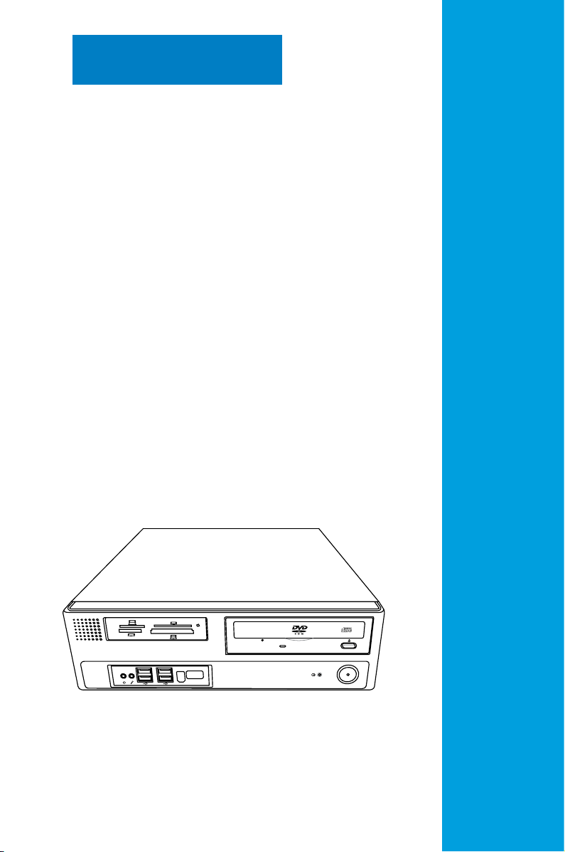
Chapter 1
This chapter gives a general
description of the desktop PC. The
chapter lists the system features
including introduction on the front and
rear panel, and internal components.
System introduction
Page 14

Chapter summary
1
1.1 Front panel .................................................................................... 1-1
1.2 Rear panel .....................................................................................
1.3 Connecting the keyboard and the mouse ..................................
1.4 Connecting other peripheral devices .........................................
1.5 Internal components ....................................................................
1-2
1-4
1-4
1-5
ASUS BP5120
Page 15
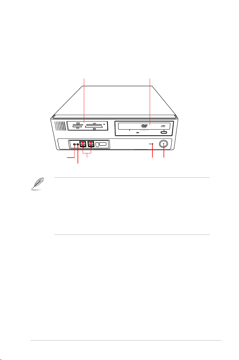
1.1 Front panel
SD
MMC
CF
MD
MS
SMC
The ASUS BP5120 Desktop PC is made up of an ASUS motherboard, a power
supply unit, a front panel, and a rear panel, etc. All of these components are
integrated in a system casing elaborately designed by ASUS.
The illustration below shows the front panel and the components on it.
1 x Storage card reader*
1 x Headphone port
1 x Microphone port
• The storage card reader, optical disk drive, and oppy disk drive are
optional items which are not included in the system package. They are
purchased separately.
• The information provided is intended as a general guide for reference.
Specications are subject to the Desktop PC you purchased.
• The storage card reader is used for Secure Digital™ / MultimediaCard /
Memory Stick® / CompactFlash® / Microdrive™ / SmartMedia® storage
cards.
4 x USB 2.0 ports
1 x Optical disk drive (ODD)*
ODD LED
Power button / Power LED
1-1ASUS BP5120
Page 16
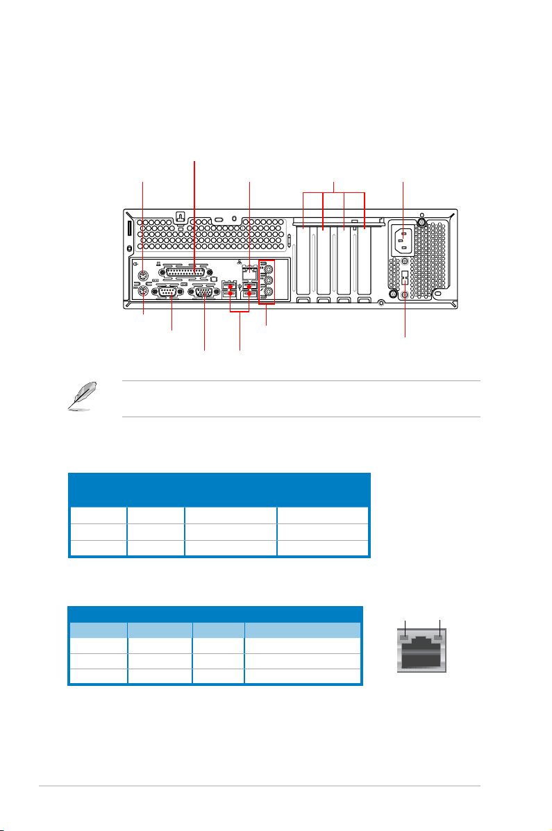
1.2 Rear panel
LINE
IN
MIC IN
15
The system rear panel includes the power connector and several I/O ports that
allow convenient connection of devices.
The illustration below shows the rear panel and the components on it.
1 x PS/2 Mouse port
1 x PS/2 Keyboard port
1 x COM port
1 x Parallel port
1 x RJ-45 port
1 x VGA port
6-Channel audio ports
4 x USB 2.0 ports
4 x low prole
Expansion slots*
The system only supports low prole PCI, PCI Express x1, and
PCI Express x16 slots.
Audio 2, 4, or 6-channel conguration
Port
Light Blue Line In Rear Speaker Out
Lime Line Out Front Speaker Out Front Speaker Out
Pink Mic In Mic In
Headset
2-channel
4-channel 6-channel
Rear Speaker Out
Bass/Center
1 x Power connector
Voltage selector
LAN port LED indications
ACT/LINK
Activity/Link Speed LED
LED
Status Description Status Description
OFF No link OFF 10 Mbps connection
ORANGE Linked ORANGE 100 Mbps connection
BLINKING Data activity GREEN 1 Gbps connection
1-2 Chapter 1: System introduction
SPEED
LED
LAN port
Page 17
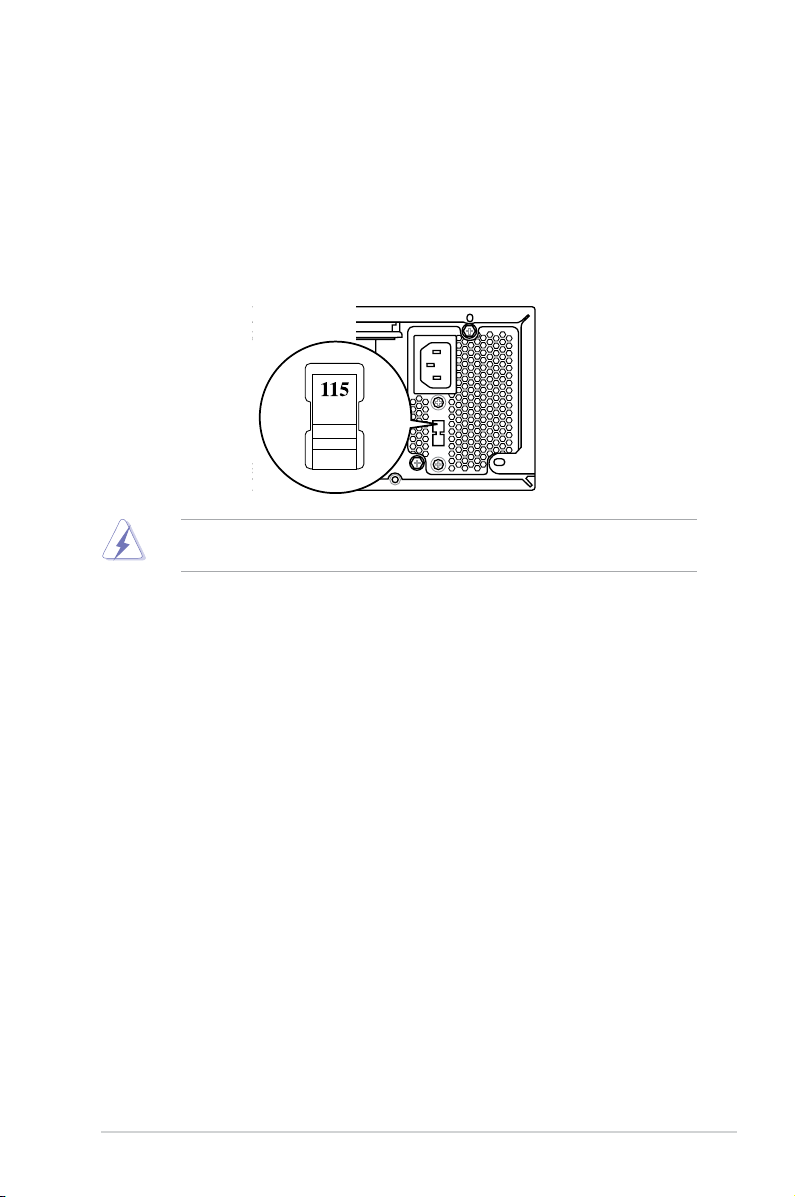
15
Selecting the voltage
The system’s power supply unit has a 115V / 230V voltage selector switch located
below the power connector. Use this switch to select the appropriate system input
voltage according to the voltage supply in your area.
If the voltage supply in your area is 100-127V, set the switch to 115V.
If the voltage supply in your area is 200-240V, set the swith to 230V.
Setting the switch to 115V in a 230V environment will seriously damage the
system!
1-3ASUS BP5120
Page 18

1.3 Connecting the keyboard and the
LINE
IN
MIC IN
15
mouse
The ASUS BP5120 Desktop PC is equipped with a PS/2 keyboard and a USB
mouse. Connect the PS/2 keyboard to the PS/2 keyboard port at the rear panel
and the USB mouse to a USB port at the rear panel or front panel as you like.
1.4 Connecting other peripheral devices
The ASUS BP5120 Desktop PC is equipped with a number of ports at the rear and
the front panels where you can connect peripheral devices to the system.
Refer to the illustration below for details.
PS/2 keyboard
PS/2 mouse
Serial port
Parallel port
VGA
RJ-45 port
USB
Line-out port
Line-in port
Expansion slots
Microphone port
Power supply
• The system only supports low prole PCI, PCI Express x16, and
PCI Express x1 cards. You can only install low prole expansion cards on
this system.
• Before you connect a peripheral device to the system, refer to the
documentation that comes with the device or contact your supplier directly
for information on how to install it.
1-4 Chapter 1: System introduction
Page 19

1.5 Internal components
The illustration below is the internal view of the system when you remove the top
cover and the chassis support bracket. The installed components are labeled
for your reference. Proceed to Chapter 2 for instructions on installing additional
system components.
8
7
6
5
4
3
1. 5.25-inch empty optical drive bay
2. Front panel cover (Removed)
3. Power supply unit
4. Expansion slots
5. ASUS motherboard
6. DIMM slots
• The optical disk drive, oppy disk drive, and storage card reader are
optional items which are not included in the system package. They are
purchased separately.
• The 5.25-inch empty optical drive bay is for a DVD-ROM / CD-RW /
DVD-RW device.
• The 3.5-inch empty optical drive bay is for a 3.5-inch hard disk drive / oppy
disk drive / USB storage card reader.
1
2
10
9
7. LGA775 socket (under the CPU
fan)
8. CPU fan and heatsink assembly
9. Storage card reader / Floppy disk
drive
10. 3.5-inch empty optical drive bay
1-5ASUS BP5120
Page 20

1-6 Chapter 1: System introduction
Page 21

SD
MMC
CF
MD
MS
SMC
Chapter 2
This chapter provides step-bystep instructions on how to install
components in the system.
Basic installation
Page 22

Chapter summary
2
2.1 Removing the covers ................................................................... 2-1
2.2 Preparation ...................................................................................
2.3 Installing a CPU ............................................................................
2.4 Installing a DIMM ..........................................................................
2.5 Installing an expansion card .......................................................
2.6 Installing a storage device ........................................................
2.7 Replacing the supporting stand and the covers .....................
2-3
2-4
2-8
2-9
2-13
2-20
ASUS BP5120
Page 23

2.1 Removing the covers
11 1
2
3
1
2.1.1 Removing the system cover
The system panel is secured with four screws on the rear panel. Before you
remove it, place the system horizontally.
To remove the system panel:
1. On the rear panel, locate the four screws that secure the cover to the
chassis. Use a Philips screw driver to remove the screws and keep them for
later use.
2. Slightly push the cover toward the rear panel until the side tabs are
disengaged from the chassis.
3. Lift the cover, then set aside.
2-1ASUS BP5120
Page 24

2.1.2 Removing the front panel assembly
S
D
M
M
C
C
F
M
D
M
S
S
M
C
1
1
2
To remove the front panel assembly:
1. Place the system vertically. Locate the front panel assembly hooks and pull
the hooks outward to release the front panel assembly.
2. Swing the left edge of the front panel assembly outward and unhook the
hinge-like tabs from the holes on the right side of the chassis to detach.
Do not use too much force when removing the front panel assembly.
2-2 Chapter 2: Basic installation
Page 25

2.2 Preparation
P5KPL-VM
R
P5KPL-VM Onboard LED
SB_PWR
ON
Standby
Power
OFF
Powered
Off
Take note of the following precautions before you install components into the
system.
• Unplug the power cables before you touch any component in the system.
•
Use a grounded wrist strap or touch a safely grounded object or a metal
object, such as the power supply case, before handling components to
avoid damaging them due to static electricity.
•
Hold components by the edges to avoid touching the ICs on them.
•
Whenever you uninstall any component, place it on a grounded antistatic
pad or in the bag that came with the component.
• Before you install or remove any component, ensure that the ATX power
supply is switched off or the power cable is detached from the power
supply. Failure to do so may cause severe damage to the motherboard,
peripherals, and components.
The system motherboard comes with an onboard standby power LED. This LED
lights up to indicate that the system is ON, in sleep mode or in soft-off mode, and
not powered OFF. Unplug the power cable from the power outlet and ensure that
the standby power LED is OFF before installing any system component.
2-3ASUS BP5120
Page 26

2.3 Installing a CPU
P5KPL-VM
R
P5KPL-VM CPU Socket 775
The motherboard comes with a surface mount LGA775 socket designed for the
Intel® Core™2 Duo / Pentium® D/ Pentium® 4 / Celeron® D processors.
• Your boxed Intel® LGA775 processor package should come with installation
instructions for the CPU, heatsink, and retention mechanism. If the
instructions in this section do not match the CPU documentation, follow the
latter.
•
Check your motherboard to ensure that the PnP cap is on the socket and
the socket contacts are not bent. Contact your retailer immediately if the
PnP cap is missing, or if you see any damage to the socket contacts/
motherboard components. ASUS will shoulder the cost of repair only if the
damage is shipment/transit-related.
• The product warranty does not cover damage to the socket contacts
resulting from incorrect CPU installation or removal.
2.3.1 CPU installation
Installing the CPU
To install a CPU:
1. Locate the CPU socket on the motherboard.
Before installing the CPU, ensure that the socket box is facing towards you and
the load lever is on your left.
2-4 Chapter 2: Basic installation
Page 27

2. Press the load lever with your thumb
(A), then move it to the left (B) until it
is released from the retention tab.
To prevent damage to the
socket pins, do not remove
the PnP cap unless you are
installing a CPU.
Retention tab
A
B
Load lever
3. Lift the load lever in the direction of
the arrow to a 135º angle.
4. Lift the load plate with your thumb
and forenger to a 100º angle (4A),
then push the PnP cap from the
load plate window to remove (4B).
5. Position the CPU over the socket,
ensuring that the gold triangle is on
the bottom-left corner of the socket
then t the socket alignment key
into the CPU notch.
PnP cap
Load plate
4B
4A
3
CPU notch
Gold
triangle
mark
Alignment key
2-5ASUS BP5120
Page 28

6. Apply Thermal Interface Material
on the CPU before closing the load
plate.
DO NOT eat the Thermal Interface
Material. If it gets into your eyes or
touches your skin, ensure that you
wash it off immediately, and seek
professional medical help.
7. Close the load plate (A), then push
the load lever (B) until it snaps into
the retention tab.
A
B
Intel® Hyper-Threading Technology
• The motherboard supports Intel® Pentium® 4 / Core™2 Duo LGA775
processors with Hyper-Threading Technology.
• Hyper-Threading Technology is supported under Windows® XP / Vista
and Linux 2.4.x (kernel) and later versions only. Under Linux, use the
Hyper-Threading compiler to compile the code. If you are using any other
operation systems, disable the Hyper-Threading Technology in the BIOS to
ensure system stability and performance.
• Installing Windows® XP Service Pack 1 or later version is recommended.
• Ensure that you enable the Hyper-Threading Technology item in the BIOS
before installing a supported operating system.
• For more information on Hyper-Threading Technology, visit www.intel.
com/info/hyperthreading.
2-6 Chapter 2: Basic installation
Page 29

2.3.2 Installing the CPU fan and heatsink assembly
The Intel® LGA775 processor requires a specially designed heatsink and fan
assembly to ensure optimum thermal condition and performance.
Ensure that the Thermal Interface Material is properly applied to the CPU
heatsink or CPU before you install the heatsink and fan assembly.
To install the CPU heatsink and fan:
1. Place the heatsink on top of the installed CPU,
ensuring that the four fasteners match the holes on the
motherboard.
2. Push down two fasteners at a time in a diagonal
sequence to secure the heatsink and fan assembly in
place.
Installing the CPU fan and heatsink assembly 1
Installing the CPU fan and heatsink assembly 2
A
B
B
A
Both kinds of fan and heatsink assemblies above apply to this motherboard.
2-7ASUS BP5120
Page 30

3. When the fan and heatsink assembly is in place, connect the CPU fan cable
P5KPL-VM
R
P5KPL-VM
Fan Connectors
GND
CPU FAN PWR
CPU FAN IN
CPU FAN PWM
CPU_FAN
CHA_FAN
GND
Rotation
+12V
PWR_FAN
GND
Rotation
+12V
to the connector on the motherboard.
Do not forget to connect the CPU fan connector! Hardware monitoring errors
can occur if you fail to plug this connector.
2.4 Installing a DIMM
To install a DDR2 DIMM:
1. Locate the two DIMM slots on the motherboard.
2. Unlock a slot by pressing the retaining clips outward.
3. Align a DIMM on the slot such that the notch on the DIMM matches the break
on the slot.
4. Firmly insert the DIMM into the slot until the retaining clips snap back in
place and the DIMM is properly seated.
• Unplug the power cables before installing a DIMM or any other component.
Failure to do so may cause damage to the motherboard and the
components on it.
• A DDR2 DIMM is keyed with a notch so that it ts in only one direction. DO
NOT force a DIMM into a slot to avoid damaging the DIMM!
2-8 Chapter 2: Basic installation
Page 31

2.5 Installing an expansion card
In the future, you may need to install expansion cards. The motherboard has
two PCI slots, one PCI Express™ x1 slot, and one PCI Express™ x16 slot. The
following subsections describe the slots and the expansion cards that they support.
The system only supports low prole PCI, PCI Express x16, and PCI Express
x1 cards. You can only install low prole expansion cards on this system.
2.5.1 Expansion card installation
Ensure that you unplug the power cord before adding or removing expansion
cards. Failure to do so may cause you physical injury and damage the
motherboard.
To install an expansion card:
1. Remove one metal bracket lock
screw with a Philips screw driver.
2. Remove the metal bracket lock
and the metal cover opposite the
slot that you intend to use.
2-9ASUS BP5120
Page 32

3. Align the card connector with the
slot and press rmly until the card
is completely seated on the slot.
Replace the metal bracket lock.
This system only supports low prole PCI, PCI Express x1, and PCI Express
x16 cards. You can only install low prole expansion cards on this system.
4. Replace the metal bracket lock
screw to secure the card.
2-10 Chapter 2: Basic installation
Page 33

2.5.2 Expansion cards
PCI slots
The PCI slots support cards such as LAN
card, SCSI card, audio card, USB card
and other cards that comply with PCI
specications. The gure shows a LAN
card installed on a PCI slot.
PCI Express x1 slot
This motherboard supports PCI Express
x1 network cards, SCSI cards and other
cards that comply with PCI Express
specications. The gure shows a
network card installed on a PCI Express
x 1 slot.
PCI Express x16 slot
This motherboard supports PCI Express
x16 graphics cards that comply with
PCI Express specications. The gure
shows a graphics card installed on a PCI
Express x16 slot.
The system only supports low prole PCI, PCI Express x16, and PCI Express
x1 cards. You can only install low prole expansion cards on this system.
2-11ASUS BP5120
Page 34

2.5.3 Standard interrupt assignments
Standard interrupt assignments
IRQ Priority Standard Function
0 1 System Timer
1 2 Keyboard Controller
2 — Redirect to IRQ#9
3 10 Communications Port (COM1)
4 11 IRQ holder for PCI steering*
5 12 Standard Floppy Disk Controller
6 13 Printer Port (LPT1)*
7 3 System CMOS/Real Time Clock
8 4 IRQ holder for PCI steering*
9 5 IRQ holder for PCI steering*
10 6 IRQ holder for PCI steering*
11 7 PS/2 Compatible Mouse Port*
12 8 Numeric Data Processor
13 9 Primary IDE Channel
* These IRQs are usually available for ISA or PCI devices.
IRQ assignments for this motherboard
A B C D E F G H
PCI1 — — — shared — — — —
PCI2 shared — — — — — — —
PCIEX16_1 shared — — — — — — —
PCIEX1_1 shared — — — — — — —
Onboard USB controller 1 — — — — — — — shared
Onboard USB controller 2 — — — shared — — — —
Onboard USB controller 3 — — shared — — — — —
Onboard USB controller 4 shared — — — — — — —
Onboard USB 2.0 controller — — — — — — — shared
Onboard HD audio shared — — — — — — —
Onboard LAN — shared — — — — — —
When using a PCI card on shared slots, ensure that the drivers support “Share
IRQ” or that the cards do not need IRQ assignments. Otherwise, conicts will
arise between the two PCI groups, making the system unstable and the card
inoperable.
2-12 Chapter 2: Basic installation
Page 35

2.6 Installing a storage device
S
D
M
M
C
C
F
M
D
M
S
S
M
C
1
1
2
Before you install a storage device to the system, remove the system cover and
front panel assembly rst.
To remove the front panel assembly:
1. Place the system vertically. Locate
the front panel assembly hooks and
pull the hooks outward to release the
front panel assembly.
2. Swing the left edge of the front
panel assembly outward and
unhook the hinge-like tabs from
the holes on the right side of the
chassis to detach.
3. Place the system horizontally. Push
the retention bracket locks (A) on
both sides toward the front panel
and disengage the supporting stand
from the tenons (B).
A
4. Remove the supporting stand and
lay it on a at and stable surface.
B
A
B
2-13ASUS BP5120
Page 36

2.6.1 Installing / Uninstalling a hard disk drive
1
2
3
2
3
Installing a hard disk drive
To install a hard disk drive:
1. Insert the hard disk to the 3.5
inch drive bay and carefully
push the disk until its screw
holes are aligned with the holes
on the supporting stand.
2. Pull the retention brackets on
both sides of the bay outward
and align the hard disk to the
retention brackets.
3. Press the retention bracket
locks until the they are parallel
to the hard disk.
4. Connect the power cable and the signal cable.
• You can install an IDE hard disk drive with an IDE power cable and an IDE
cable (A) into the drive bay.
• You can installl a Serial ATA hard disk drive with a Serial ATA power cable
and a Serial ATA cable (B) into the drive bay.
A
IDE ribbon cable
Power cable
Do not place the IDE ribbon cable too close to the power fan in case it interferes
with the system ventilation.
2-14 Chapter 2: Basic installation
B
SATA power cable
SATA cable
Page 37

Uninstalling a hard disk drive
3
2
1
2
1
To uninstall a hard disk drive:
1. Pull the retention bracket locks
upward until they are vertical to
the hard disk.
2. Push the retention brackets
inward to disengage the hard
disk.
3. Remove the hard disk from the
back of the supporting stand.
Before you uninstalll a hard disk drive, be certain to unplug the cables.
2-15ASUS BP5120
Page 38

2.6.2 Installing / Uninstalling a card reader / a oppy disk
2
1
3
2
3
drive
Installing a card reader
To install a card reader:
1. Insert the card reader to the 3.5 inch drive bay and carefully push the card
reader until its screw holes are aligned with the holes on the supporting
stand.
2. Pull the retention brackets on both sides of the bay outward and align the
hard disk to the retention brackets.
3. Press the retention bracket locks until they are parallel to the card reader.
4. Connect the power cable and the signal cable..
Installing a oppy disk drive
Follow the same instructions as shown in the section of “Installing a card reader“ to
install a oppy disk drive.
2-16 Chapter 2: Basic installation
Page 39

Uninstalling a card reader / oppy disk drive
2
1
2
1
3
To uninstall a card reader:
1. Pull the retention bracket locks upward until they are vertical to the hard disk.
2. Push the retention brackets inward to disengage the card reader.
3. Remove the card reader from the back of the supporting stand.
Before you uninstall a card reader, be certain to unplug the cables.
UnInstalling a oppy disk drive
Follow the same instructions as shown in the section of “Uninstalling a card reader“
to uninstall a oppy disk drive.
2-17ASUS BP5120
Page 40

2.6.3 Installing / Uninstalling an optical disk drive
2
3
1
3
1
Installing an optical disk drive
To install an optical disk drive:
1. Insert the optical disk to the 5.25 inch drive bay and carefully push the disk
until its screws holes align with the holes on the supporting stand.
2. Pull the retention brackets on both sides of the bay outward and align the
optical disk to the retention brackets.
3. Press the retention bracket locks until they are parallel to the hard disk.
• You can install an IDE optical disk drive with an IDE power cable and
an IDE cable (A) into the drive bay.
• You can installl a Serial ATA optical disk drive with a Serial ATA power
cable and a Serial ATA cable (B) into the drive bay.
A
IDE
Power cable
IDE cable
Connect the audio plug on the optical disk to the 4-pin CD connector on the
motherboard to receive audio input.
B
SATA cable
SATA power cable
2-18 Chapter 2: Basic installation
Page 41

Uninstalling an optical disk drive
2
3
1
3
1
To uninstall an optical disk drive:
1. Pull the retention bracket locks upward until they are vertical to the hard disk.
2. Push the retention brackets inward to disengage the hard disk.
3. Remove the optical disk from the back of the supporting stand.
Before you uninstall an optical disk drive, be certain to unplug the cables.
2-19ASUS BP5120
Page 42

2.7 Replacing the supporting stand and
S
D
M
M
C
C
F
M
D
M
S
S
M
C
1
1
2
the covers
After you have installed all the necessary components on the system, replace the
supporting stand and the covers following the instructions in this section.
2.7.1 Replace the supporting stand
To replace the supporting stand:
1. Insert the supporting stand into the
tenons (A).
2. Push down the retention bracket
locks (B) to secure the supporting
stand to the system.
2.7.2 Replace the front panel assembly
To replace the front panel assembly:
1. Place the system vertically. Insert
the hinge-like tabs on the right edge
of the front panel assembly into
the holes on the right side of the
chassis.
2. Swing the front panel assembly
to the left, then insert the hooks
to the chassis until the front panel
assembly ts in place.
B
A
B
A
2-20 Chapter 2: Basic installation
Page 43

2.7.3 Replacing the system cover
2
1
2
2
2
To replace the system cover:
1. Place the system horizontally. Slightly push the cover toward the front panel
until the side tabs are engaged into the chassis.
2. Secure the cover with the four screws that you removed earlier.
2-21ASUS BP5120
Page 44

2-22 Chapter 2: Basic installation
Page 45

SD
MMC
CF
MD
MS
SMC
Chapter 3
This chapter helps you to power up the
system and install drivers and utilities
from the support CD.
Getting started
Page 46

Chapter summary
3
3.1 Installing an operating system ................................................... 3-1
3.2 Powering your system .................................................................
3.3 Support CD information ..............................................................
3.4 Recovery CD .................................................................................
3-1
3-2
3-8
ASUS BP5120
Page 47

3.1 Installing an operating system
This motherboard supports Windows® 2000 / XP / Vista operating systems (OS).
Always install the latest OS version and corresponding updates to maximize the
features of your hardware. When you start the system for the rst time, the system
automatically detects the built-in audio and graphics chips and attempts to install
the drivers. Select NO when a window appears asking if you want to restart the
system. Install drivers according to the instructions in the following sections.
• To ensure the OS can work properly, install the VGA drivers from the
bundled Support CD.
• Motherboard settings and hardware options vary. Use the setup
procedures presented in this chapter for reference only. Refer to your OS
documentation for detailed information.
3.2 Powering your system
Press the Power button to power up the system, then the Power LED turns on.
ASUS BP5120 3-1
Page 48

3.3 Support CD information
The support CD that comes with the system package contains the drivers, software
applications, and utilities that you can install to avail all system features.
The contents of the support CD are subject to change at any time without
notice. Visit the ASUS website at http://www.asus.com for updates.
3.3.1 Running the support CD
Place the support CD to the optical drive. The CD automatically displays the
Drivers menu if Autorun is enabled in your computer.
Click an icon to
display support
CD/motherboard
information
Click an item to install
If Autorun is NOT enabled in your computer, browse the contents of the support
CD to locate the le ASSETUP.EXE from the BIN folder. Double-click the
ASSETUP.EXE to run the CD.
3-2 Chapter 3: Getting started
Page 49

3.3.2 Drivers menu
The drivers menu shows the available device drivers if the system detects installed
devices. Install the necessary drivers to activate the devices.
ASUS InstAll-Drivers Installation Wizard
Installs the ASUS InstAll-Drivers Installation Wizard.
Intel(R) Chipset Inf Update Program
Installs the Intel® chipset Inf update program.
Realtek Audio Driver
Installs the Realtek® ALC883 audio driver and application.
Intel(R) Graphics Accelerator Driver
Installs the Intel® graphics accelerator driver.
Atheros L1 Gigabit Ethernet Driver
Installs the Atheros L1 Gigabit Ethernet driver.
USB 2.0 Driver
Installs the Universal Serial Bus 2.0 (USB 2.0) driver.
ASUS BP5120 3-3
Page 50

3.3.3 Utilities menu
The Utilities menu shows the applications and other software that the motherboard
supports. Tap an item from the screen to install.
ASUS InstAll-Installation Wizard for Utilities
Installs all of the utilities through the Installation Wizard.
ASUS Update
Allows you to download the latest version of the BIOS from the ASUS website.
Before using the ASUS Update, ensure that you have an Internet connection so
that you can connect to the ASUS website.
ASUS PC Probe II
This smart utility monitors the fan speed, CPU temperature, and system voltage,
and alerts you of any detected problems. This utility helps you keep your computer
in healthy operating condition.
Adobe Acrobat Reader 7.0
Installs the Adobe Acrobat Reader 7.0.
The manuals in the Support CD are in PDF (Portable Document Format) format,
which can be opened with Adobe Acrobat Reader. Refer to the additional
instruction for details.
Athero Ethernet utility
Installs the Athero Ethernet utility.
3-4 Chapter 3: Getting started
Page 51

3.3.4 Manuals menu
The Support CD includes the manual of Realtek HD Audio.
The manual is in PDF format. To open it, install the Adobe Acrobat Reader from
the Utilities menu.
3.3.5 ASUS contact information
Click the Contact tab to display the ASUS contact information.
ASUS BP5120 3-5
Page 52

3.3.6 Other information
The icons on the top right corner of the screen give additional information on the
motherboard and the contents of the support CD. Click an icon to display the
specied information.
Motherboard Info
Displays the general specications of the motherboard.
Browse this CD
Displays the support CD contents in graphical format.
3-6 Chapter 3: Getting started
Page 53

Technical support Form
Displays the ASUS Technical Support Request Form that you have to ll out when
requesting technical support.
Filelist
Displays the contents of the support CD and a brief description of each in text
format.
ASUS BP5120 3-7
Page 54

3.4 Recovery CD
The ASUS PC Recovery CD assists you in reinstalling the OS and restoring it to
its original working state. Before using the recovery CD, copy your data les to a
USB device or to a network drive and make note of any customized conguration
settings such as network settings.
To recover a Windows XP OS:
1. Insert the rst Recovery CD into the Optical Disk Drive. Press
ASUS logo appears . Select the optical drive as the boot device.
2. Select
3. A conrmation screen pops up. Click
4. Check
5. A list displays the contents you are going to recover. Click
6. Insert the second CD, then click
7. Insert the Support CD, then click
8. After the system reboots, the Window XP will begin system congurations.
Recover system to a partition or Recovery system to entire HD.
Click Next.
Next to conrm.
I accept from the succeeding screen and click Next.
The recovery process starts.
OK.
OK. The system restarts.
Follow the onscreen instructions to complete the process, and then restarts
the system. Adjust the screen to a suitable display resolution.
The ASUS PC Recovery CD is for ASUS Desktop PC only. DO NOT use it on
other systems. Visit the ASUS website at www.asus.com for any updates.
<F8> when the
Yes to conrm.
3-8 Chapter 3: Getting started
Page 55

To recover a Windows Vista OS:
1. Turn on your ASUS Desktop PC and press
2. Insert the recovery CD into the optical drive when a
F8 when the ASUS logo appears.
Please select boot
device menu appears. Select the optical drive as the boot device and then
press Enter to continue.
If you want to recover the system from the hidden partition, press F9 when the
ASUS logo appears. Then follow the instructions 3-6 below.
3. After the system reboots, an ASUS Preload window appears. Press
Next to
continue.
4. Select where to install a new system. Options are:
Recover Windows to rst partition only:
This option will delete only the rst partition, allowing you to keep other
partitions, and create a new system partition as drive “C”.
Recover Windows to entire HD:
This option will delete all partitions from your hard disk and create a new
system partition as drive “C”.
Recover Windows to entire HD with 2 partitions:
This option will delete all partitions from your hard disk and create two
new system partitions. The rst partition takes up 60% of the whole hard
disk size and the second partition takes up 40%. The new system will be
installed in the rst partition. You can back up your data in the second
partition.
5. When a window appears querying
Are you sure you want to recover
now, click Finish. The process percentage nished will be displayed on the
screen.
6. When
Recovery nish message appears, click OK and the system restarts.
After it restarts, follow the onscreen instructions to complete system
congurations.
The ASUS PC Recovery CD is for ASUS Desktop PC only. DO NOT use it on
other systems. Visit the ASUS website at www.asus.com for any updates.
ASUS BP5120 3-9
Page 56

3-10 Chapter 3: Getting started
 Loading...