

ASUS BM6360, BM6660, BP6260, MD710, SD710 User Manual
ASUS Desktop PC
BM6660/MD710
BP6260/SD710
BM6360
BM6660/MD710
User Manual
BM6360
BP6260/SD710

ENGLISH
E6310
First Edition
January 2011
Copyright © 2011 ASUSTeK Computer Inc. All Rights Reserved.
No part of this manual, including the products and software described in it, may be reproduced,
transmitted, transcribed, stored in a retrieval system, or translated into any language in any form or by any
means, except documentation kept by the purchaser for backup purposes, without the express written
permission of ASUSTeK Computer Inc. (“ASUS”).
Product warranty or service will not be extended if: (1) the product is repaired, modifi ed or altered, unless
such repair, modifi cation of alteration is authorized in writing by ASUS; or (2) the serial number of the
product is defaced or missing.
ASUS PROVIDES THIS MANUAL “AS IS” WITHOUT WARRANTY OF ANY KIND, EITHER EXPRESS
OR IMPLIED, INCLUDING BUT NOT LIMITED TO THE IMPLIED WARRANTIES OR CONDITIONS OF
MERCHANTABILITY OR FITNESS FOR A PARTICULAR PURPOSE. IN NO EVENT SHALL ASUS, ITS
DIRECTORS, OFFICERS, EMPLOYEES OR AGENTS BE LIABLE FOR ANY INDIRECT, SPECIAL,
INCIDENTAL, OR CONSEQUENTIAL DAMAGES (INCLUDING DAMAGES FOR LOSS OF PROFITS,
LOSS OF BUSINESS, LOSS OF USE OR DATA, INTERRUPTION OF BUSINESS AND THE LIKE),
EVEN IF ASUS HAS BEEN ADVISED OF THE POSSIBILITY OF SUCH DAMAGES ARISING FROM ANY
DEFECT OR ERROR IN THIS MANUAL OR PRODUCT.
SPECIFICATIONS AND INFORMATION CONTAINED IN THIS MANUAL ARE FURNISHED FOR
INFORMATIONAL USE ONLY, AND ARE SUBJECT TO CHANGE AT ANY TIME WITHOUT NOTICE,
AND SHOULD NOT BE CONSTRUED AS A COMMITMENT BY ASUS. ASUS ASSUMES NO
RESPONSIBILITY OR LIABILITY FOR ANY ERRORS OR INACCURACIES THAT MAY APPEAR IN THIS
MANUAL, INCLUDING THE PRODUCTS AND SOFTWARE DESCRIBED IN IT.
Products and corporate names appearing in this manual may or may not be registered trademarks or
copyrights of their respective companies, and are used only for identifi cation or explanation and to the
ownersʼ benefi t, without intent to infringe.
ii

Contents
Notices .......................................................................................................... iv
Safety information ..........................................................................................vi
Conventions used in this guide ..................................................................... vii
Where to fi nd more information .................................................................... vii
Package contents ........................................................................................ viii
Chapter 1: Getting started
Welcome! .................................................................................................... 1-1
Getting to know your computer ................................................................... 1-1
Setting up your computer .......................................................................... 1-10
Turning your computer ON/OFF ............................................................... 1-15
Chapter 2: Using Windows® 7
Starting for the fi rst time .............................................................................. 2-1
®
Using Windows
Managing your fi les and folders .................................................................. 2-5
Restoring your system ................................................................................ 2-7
Protecting your computer ............................................................................ 2-7
Getting Windows
Chapter 3: Connecting devices to your computer
Connecting a USB storage device .............................................................. 3-1
Connecting microphone and speakers ....................................................... 3-2
7 desktop ......................................................................... 2-2
®
Help and Support .......................................................... 2-9
ENGLISH
Chapter 4: Using your computer
Proper posture when using your Desktop PC............................................. 4-1
Using the optical drive (on selected models only) ...................................... 4-2
Chapter 5: Connecting to the Internet
Wired connection ........................................................................................ 5-1
Chapter 6: Using the utilities
ASUS AI Suite II .......................................................................................... 6-1
ASUS AI Manager ....................................................................................... 6-7
Recovering your system ............................................................................. 6-9
Chapter 7: Troubleshooting
Troubleshooting .......................................................................................... 7-1
iii

Notices
ENGLISH
REACH
Complying with the REACH (Registration, Evaluation, Authorisation, and Restriction of
Chemicals) regulatory framework, we published the chemical substances in our products at
ASUS REACH website at http://csr.asus.com/english/REACH.htm
Federal Communications Commission Statement
This device complies with Part 15 of the FCC Rules. Operation is subject to the following two
conditions:
• This device may not cause harmful interference; and
• This device must accept any interference received including interference that may cause
undesired operation.
This equipment has been tested and found to comply with the limits for a Class B digital
device, pursuant to Part 15 of the FCC Rules. These limits are designed to provide
reasonable protection against harmful interference in a residential installation. This
equipment generates, uses and can radiate radio frequency energy and, if not installed
and used in accordance with manufacturerʼs instructions, may cause harmful interference
to radio communications. However, there is no guarantee that interference will not occur
in a particular installation. If this equipment does cause harmful interference to radio or
television reception, which can be determined by turning the equipment off and on, the user
is encouraged to try to correct the interference by one or more of the following measures:
• Reorient or relocate the receiving antenna.
• Increase the separation between the equipment and receiver.
• Connect the equipment to an outlet on a circuit different from that to which the receiver is
connected.
• Consult the dealer or an experienced radio/TV technician for help.
The use of shielded cables for connection of the monitor to the graphics card is required
to assure compliance with FCC regulations. Changes or modifi cations to this unit not
expressly approved by the party responsible for compliance could void the userʼs authority
to operate this equipment.
iv

RF exposure warning
This equipment must be installed and operated in accordance with provided instructions and
the antenna(s) used for this transmitter must be installed to provide a separation distance of
at least 20 cm from all persons and must not be co-located or operating in conjunction with
any other antenna or transmitter. End-users and installers must be provide with antenna
installation instructions and transmitter operating conditions for satisfying RF exposure
compliance.
Canadian Department of Communications Statement
This digital apparatus does not exceed the Class B limits for radio noise emissions from
digital apparatus set out in the Radio Interference Regulations of the Canadian Department of
Communications.
This class B digital apparatus complies with Canadian ICES-003.
Macrovision Corporation Product Notice
This product incorporates copyright protection technology that is protected by method
claims of certain U.S. patents and other intellectual property rights owned by Macrovision
Corporation and other rights owners. Use of this copyright protection technology must be
authorized by Macrovision Corporation, and is intended for home and other limited viewing
uses only unless otherwise authorized by Macrovision Corporation. Reverse engineering
or disassembly is prohibited.
Lithium-Ion Battery Warning
CAUTION: Danger of explosion if battery is incorrectly replaced. Replace only with the
same or equivalent type recommended by the manufacturer. Dispose of used batteries
according to the manufacturerʼs instructions.
ENGLISH
v

Safety information
ENGLISH
• DO NOT place on uneven or unstable work surfaces. Seek servicing if the casing has
been damaged.
• DO NOT expose to dirty or dusty environments. DO NOT operate during a gas leak.
• DO NOT place or drop objects on top and do not shove any foreign objects into the
Desktop PC.
• DO NOT expose to strong magnetic or electrical fi elds.
• DO NOT expose to or use near liquids, rain, or moisture. DO NOT use the modem during
electrical storms.
• Battery safety warning: DO NOT throw the battery in fi re. DO NOT short circuit the
contacts. DO NOT disassemble the battery.
• Use this product in environments with ambient temperatures between 5˚C (41F)and
40˚C (104F).
• DO NOT cover the vents on the Desktop PC to prevent the system from getting
overheated.
• DO NOT use damaged power cords, accessories, or other peripherals.
•
To prevent electrical shock hazard, disconnect the power cable from the electrical outlet
before relocating the system.
•
Seek professional assistance before using an adapter or extension cord. These devices
could interrupt the grounding circuit.
•
Ensure that your power supply is set to the correct voltage in your area. If you are not
sure about the voltage of the electrical outlet you are using, contact your local power
company.
•
If the power supply is broken, do not try to fi x it by yourself. Contact a qualifi ed service
technician or your retailer.
Disconnect the AC power and peripherals before cleaning. Wipe the Desktop PC using a
clean cellulose sponge or chamois cloth dampened with solution of nonabrasive detergent
and a few drops of warm water then remove any extra moisture with a dry cloth.
vi

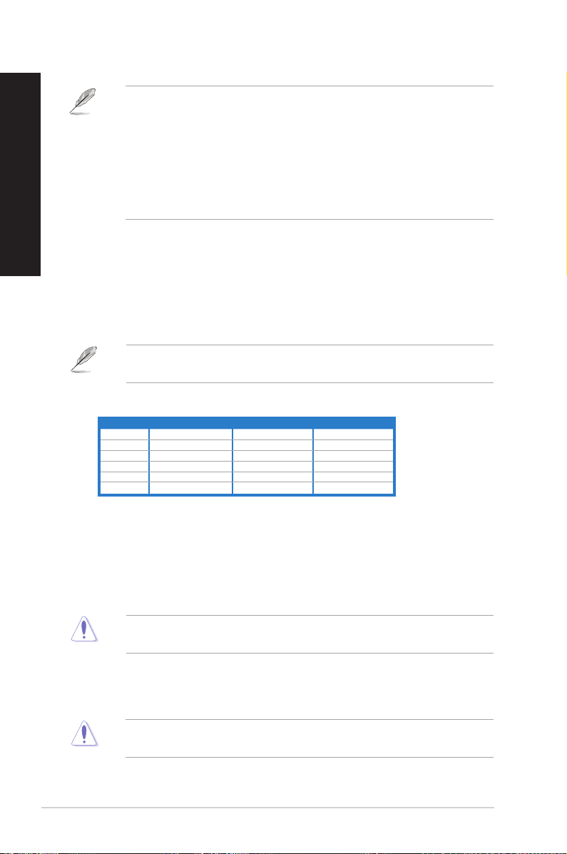
Conventions used in this guide
To ensure that you perform certain tasks properly, take note of the following symbols used
throughout this manual.
DANGER/WARNING
when trying to complete a task.
CAUTION: Information to prevent damage to the components
when trying to complete a task.
IMPORTANT: Instructions that you MUST follow to complete a
task.
NOTE: Tips and additional information to help you complete a
task.
: Information to prevent injury to yourself
Where to fi nd more information
Refer to the following sources for additional information and for product and software
updates.
ASUS websites
The ASUS website provides updated information on ASUS hardware and software
products. Refer to the ASUS website www.asus.com.
ASUS Local Technical Support
Visit ASUS website at http://support.asus.com/contact for the contact information of
local Technical Support Engineer.
ENGLISH
vii
Package contents
ENGLISH
Check your system package for the following items.
Standard items
1. ASUS Desktop PC with
• ASUS Desktop x1
• Mouse x1
• Keyboard x1
2. Cables
• Power cord x1
3. Accessories
• Mouse pad x1
4. DVD
• Support DVD x1
5. Documentation
• User Manual x1
• Warranty card x1
Optional items
1. Optical disk drive (ODD)
2. Memory card reader
3. LAN cable
4. Power strip
If any of the above items is damaged or missing, contact your retailer immediately.
viii
Specifi cations depend on the desktop PC you purchased. Check with your supplier for the
exact specifi cations.

Chapter 1
Getting started
Welcome!
Thank you for purchasing the ASUS Desktop PC!
The ASUS Desktop PC provides cutting-edge performance, uncompromised reliability, and
user-centric utilities. All these values are encapsulated in a stunningly futuristic and stylish
system casing.
Read the ASUS Warranty Card before setting up your ASUS Desktop PC.
Getting to know your computer
Illustrations are for reference only. The ports and their locations, and the chassis color vary
with different models.
ASUS BM6660/MD710, BP6260/SD710, BM6360 1-1
ENGLISH
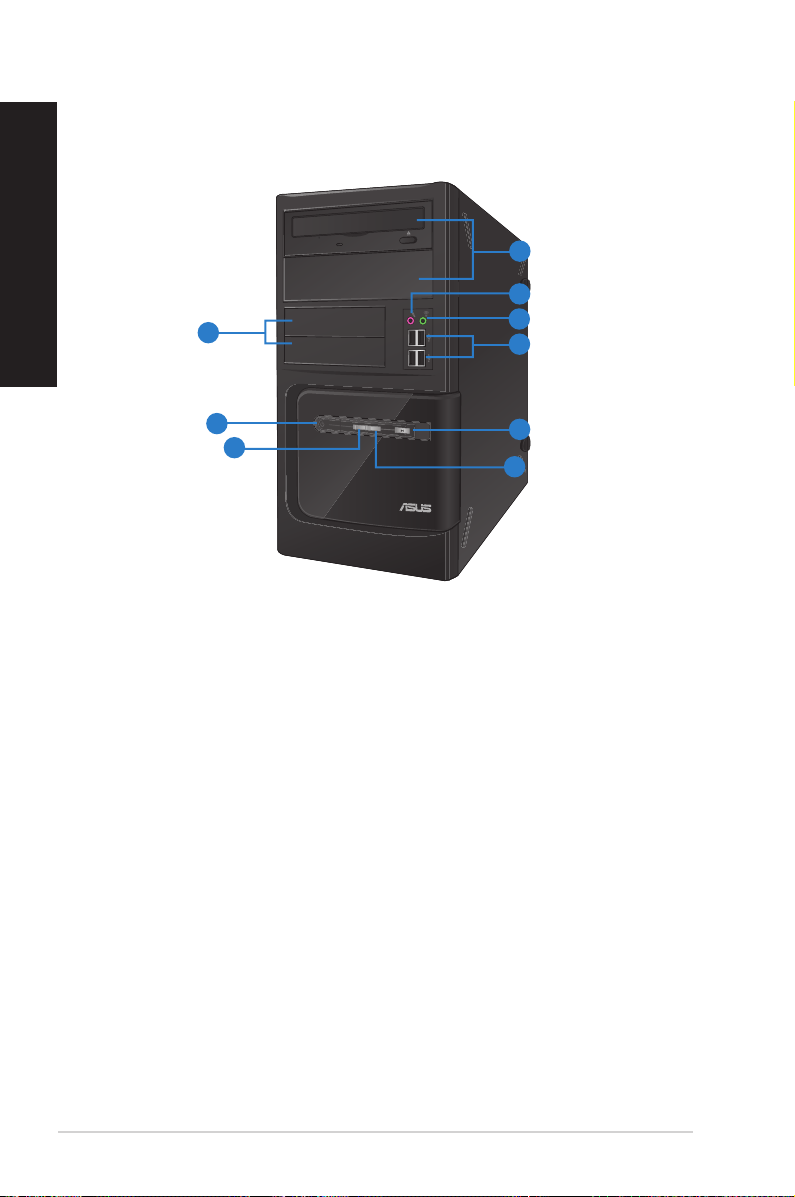
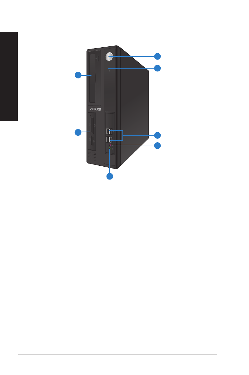
Front panel
1
2
9
3
4
8
7
5
6
BM6660/MD710
1. 2 x 5.25 inch optical disk drive bays. The 5.25 inch optical disk drive bays are for
5.25 inch DVD-ROM / CD-RW / DVD-RW devices.
2. Microphone port (pink). This port connects to a microphone.
3. Headphone port (lime). This port connects to a headphone or speaker.
4. USB 2.0 ports. These Universal Serial Bus 2.0 (USB 2.0) ports connect to USB 2.0
devices such as a mouse, printer, scanner, camera, PDA, and others.
5. Reset button. Press this button to reboot your computer.
6. HDD LED. This LED lights up when the hard disk drive operates.
7. Power LED. This LED lights up when you turn on your computer.
8. Power button. Press this button to turn on your computer.
9. 2 x 3.5 inch drive bays. The 3.5 inch drive bays are for 3.5 inch hard disk drives /
memory card readers.
1-2 Chapter 1: Getting started
1
9
8
7
6
2
3
4
5
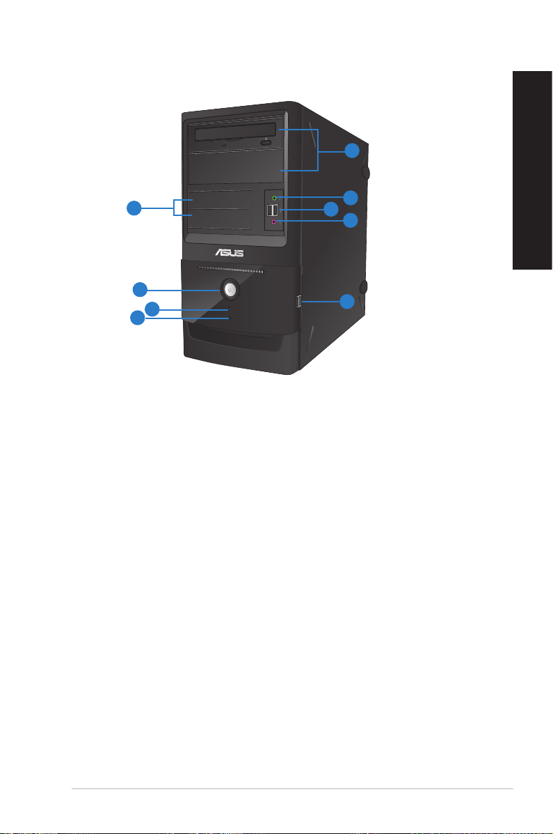
BM6360
1. 2 x 5.25 inch optical disk drive bays. The 5.25 inch optical disk drive bays are for
5.25 inch DVD-ROM / CD-RW / DVD-RW devices.
2. Headphone port (lime). This port connects to a headphone or speaker.
3. USB 2.0 ports. These Universal Serial Bus 2.0 (USB 2.0) ports connect to USB 2.0
devices such as a mouse, printer, scanner, camera, PDA, and others.
4. Microphone port (pink). This port connects to a microphone.
5. USB 2.0 ports. These Universal Serial Bus 2.0 (USB 2.0) ports connect to USB 2.0
devices such as a mouse, printer, scanner, camera, PDA, and others.
6. HDD LED. This LED lights up when the hard disk drive operates.
7. Reset button. Press this button to reboot your computer.
8. Power button. Press this button to turn on your computer.
9. 2 x 3.5 inch drive bays. The 3.5 inch drive bays are for 3.5 inch hard disk drives /
memory card readers.
ENGLISH
ASUS BM6660/MD710, BP6260/SD710, BM6360 1-3
ENGLISH
7
6
1
2
3
5
4
BP6260
1. 5.25 inch optical disk drive bay. The 5.25 inch optical disk drive bay is for 5.25 inch
DVD-ROM / CD-RW / DVD-RW devices.
2. 3.5 inch drive bays. The 3.5 inch drive bays are for 3.5 inch hard disk drives / memory
card readers.
3. Headphone port (lime). This port connects to a headphone or speaker.
4. Microphone port (pink). This port connects to a microphone.
5. USB 2.0 ports. These Universal Serial Bus 2.0 (USB 2.0) ports connect to USB 2.0
devices such as a mouse, printer, scanner, camera, PDA, and others.
6. HDD LED. This LED lights up when the hard disk drive operates.
7. Power button. Press this button to turn on your computer.
1-4 Chapter 1: Getting started
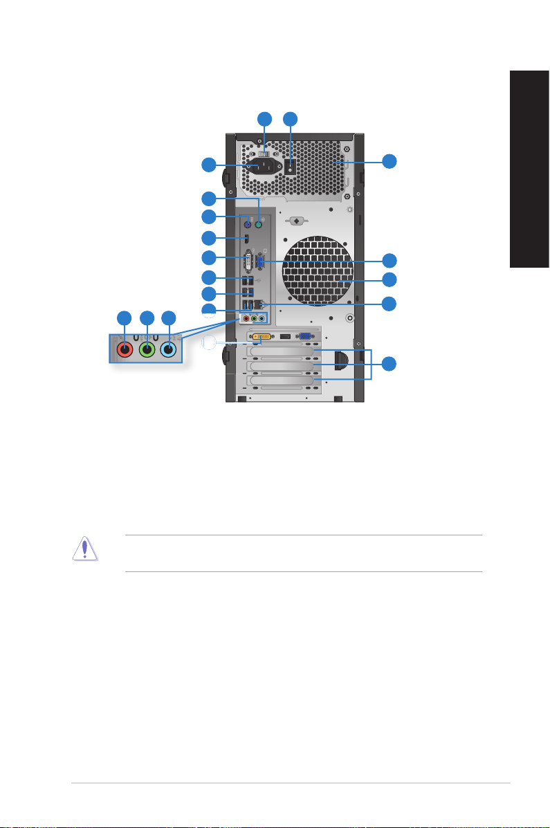
Rear panel
12
16
17
16
15
14
10
11 12
3
4
5
6
7
8
9
8
13
BM6660/MD710 and BM6360
1. Power switch. Switch to turn ON/OFF the power supply to your computer.
2. Voltage selector. Use this switch to select the appropriate system input voltage
according to the voltage supply in your area. If the voltage supply in your area is 100127V, set the switch to 115V. If the voltage supply in your area is 200-240V, set the
switch to 230V.
Setting the switch to 115V in a 230V environment or 230V in a 115V environment will
seriously damage the system!
ENGLISH
3 . Power connector. Plug the power cord to this connector.
4. PS/2 mouse port (green). This port is for a PS/2 mouse.
5. PS/2 keyboard port (purple). This port is for a PS/2 keyboard.
6. Display port. This port connects to a display monitor.
7. DVI-D port. This port is for any DVI-D compatible device and is HDCP compliant
allowing playback of HD DVD, Blu-ray, and other protected content.
ASUS BM6660/MD710, BP6260/SD710, BM6360 1-5
8. USB 2.0 ports. These Universal Serial Bus 2.0 (USB 2.0) ports connect to USB 2.0
ENGLISH
9. USB 3.0 ports. These Universal Serial Bus 3.0 (USB 3.0) ports connect to USB 3.0
devices such as a mouse, printer, scanner, camera, PDA, and others.
devices such as a mouse, printer, scanner, camera, PDA, and others.
• DO NOT connect a keyboard / mouse to any USB 3.0 port when installing Windows
operating system.
• Due to USB 3.0 controller limitation, USB 3.0 devices can only be used under Windows
OS environment and after the USB 3.0 driver installation.
• USB 3.0 devices can only be used as data storage only.
• We strongly recommend that you connect USB 3.0 devices to USB 3.0 ports for faster
and better performance for your USB 3.0 devices.
®
10. Microphone port (pink). This port connects to a microphone.
11. Line Out port (lime). This port connects to a headphone or speaker. In a 4, 6, or
8-channel confi guration, the function of this port becomes Front Speaker Out.
12. Line In port (light blue). This port connects to a tape, CD, DVD player, or other audio
sources.
Refer to the audio confi guration table below for the function of the audio ports in a 2, 4, or
6-channel confi guration.
Audio 2, 4, or 6-channel confi guration
Port Headset 2-channel 4-channel 6-channel
Light Blue Line In Line In Line In
Lime Line Out Front Speaker Out Front Speaker Out
Pink Mic In Mic In Mic In
Orange – – Center/Subwoofer
Black – Rear Speaker Out Rear Speaker Out
Gray – – –
®
13. Expansion slot brackets. Remove the expansion slot bracket when installing an
expansion card.
14. ASUS Graphics Card (on selected models only). The display output ports on this
optional ASUS Graphics Card may vary with different models.
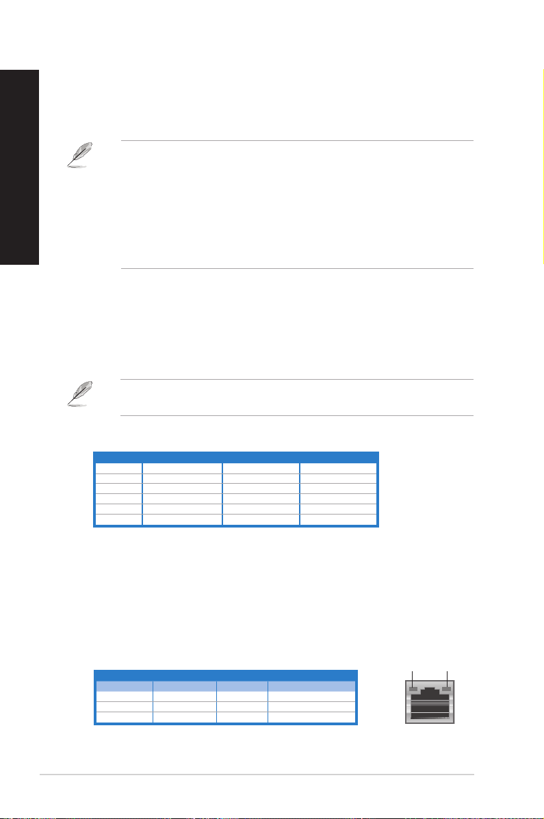
15. LAN (RJ-45) port. This port allows Gigabit connection to a Local Area Network (LAN)
through a network hub.
LAN port LED indications
Activity/Link LED Speed LED
Status Description Status Description
OFF No link OFF 10Mbps connection
ORANGE Linked ORANGE 100Mbps connection
BLINKING Data activity GREEN 1Gbps connection
1-6 Chapter 1: Getting started
ACT/LINK
LED
LAN port
SPEED
LED
16. Air vents. These vents allow air ventilation.
DO NOT block the air vents on the chassis. Always provide proper ventilation for your
computer.
17. VGA port. This port is for VGA-compatible devices such as a VGA monitor.
1
2
3
ENGLISH
4
5
6
5
7 8 9
10
11
15
14
13
12
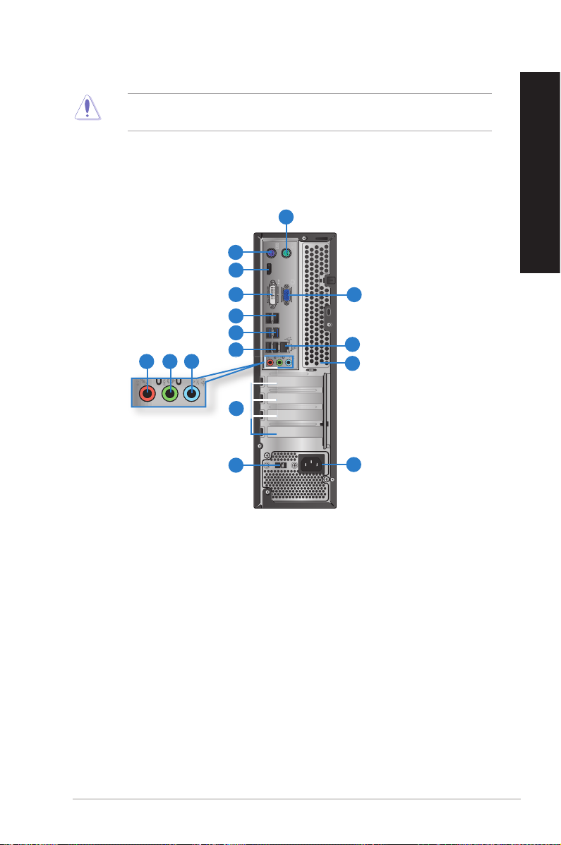
BP6260
1. PS/2 mouse port (green). This port is for a PS/2 mouse.
2. PS/2 keyboard port (purple). This port is for a PS/2 keyboard.
3. Display port. This port connects to a display monitor.
4. DVI-D port. This port is for any DVI-D compatible device and is HDCP compliant
allowing playback of HD DVD, Blu-ray, and other protected content.
5. USB 2.0 ports. These Universal Serial Bus 2.0 (USB 2.0) ports connect to USB 2.0
devices such as a mouse, printer, scanner, camera, PDA, and others.
6. USB 3.0 ports. These Universal Serial Bus 3.0 (USB 3.0) ports connect to USB 3.0
devices such as a mouse, printer, scanner, camera, PDA, and others.
ASUS BM6660/MD710, BP6260/SD710, BM6360 1-7
ENGLISH
7. Microphone port (pink). This port connects to a microphone.
8. Line Out port (lime). This port connects to a headphone or speaker. In a 4, 6, or
9. Line In port (light blue). This port connects to a tape, CD, DVD player, or other audio
Audio 2, 4, or 6-channel confi guration
• DO NOT connect a keyboard / mouse to any USB 3.0 port when installing Windows®
operating system.
• Due to USB 3.0 controller limitation, USB 3.0 devices can only be used under Windows
OS environment and after the USB 3.0 driver installation.
• USB 3.0 devices can only be used as data storage only.
• We strongly recommend that you connect USB 3.0 devices to USB 3.0 ports for faster
and better performance for your USB 3.0 devices.
8-channel confi guration, the function of this port becomes Front Speaker Out.
sources.
Refer to the audio confi guration table below for the function of the audio ports in a 2, 4, or
6-channel confi guration.
Port Headset 2-channel 4-channel 6-channel
Light Blue Line In Line In Line In
Lime Line Out Front Speaker Out Front Speaker Out
Pink Mic In Mic In Mic In
Orange – – Center/Subwoofer
Black – Rear Speaker Out Rear Speaker Out
Gray – – –
®
10. Expansion slot brackets. Remove the expansion slot bracket when installing an
expansion card.
11. Voltage selector. Use this switch to select the appropriate system input voltage
according to the voltage supply in your area. If the voltage supply in your area is 100127V, set the switch to 115V. If the voltage supply in your area is 200-240V, set the
switch to 230V.
Setting the switch to 115V in a 230V environment or 230V in a 115V environment will
seriously damage the system!
12. Power connector. Plug the power cord to this connector.
13. Air vents. These vents allow air ventilation
DO NOT block the air vents on the chassis. Always provide proper ventilation for your
computer.
1-8 Chapter 1: Getting started

14. LAN (RJ-45) port. This port allows Gigabit connection to a Local Area Network (LAN)
through a network hub.
LAN port LED indications
Activity/Link LED Speed LED
Status Description Status Description
OFF No link OFF 10Mbps connection
ORANGE Linked ORANGE 100Mbps connection
BLINKING Data activity GREEN 1Gbps connection
ACT/LINK
LED
LAN port
SPEED
LED
15. VGA port. This port is for VGA-compatible devices such as a VGA monitor.
ENGLISH
ASUS BM6660/MD710, BP6260/SD710, BM6360 1-9
Setting up your computer
ENGLISH
This section guides you through connecting the main hardware devices, such as the external
monitor, keyboard, mouse, and power cord, to your computer.
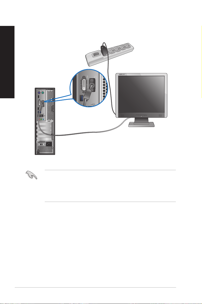
Connecting an external monitor
Using the ASUS Graphics Card (on selected models only)
Connect your monitor to the display output port on the discrete ASUS Graphics Card.
To connect an external monitor using the ASUS Graphics Card:
1. Connect your monitor to a display output port on the ASUS Graphics Card.
2. Plug your monitor to a power source.
The display output ports on the ASUS Graphics Card may vary with different models.
1-10 Chapter 1: Getting started
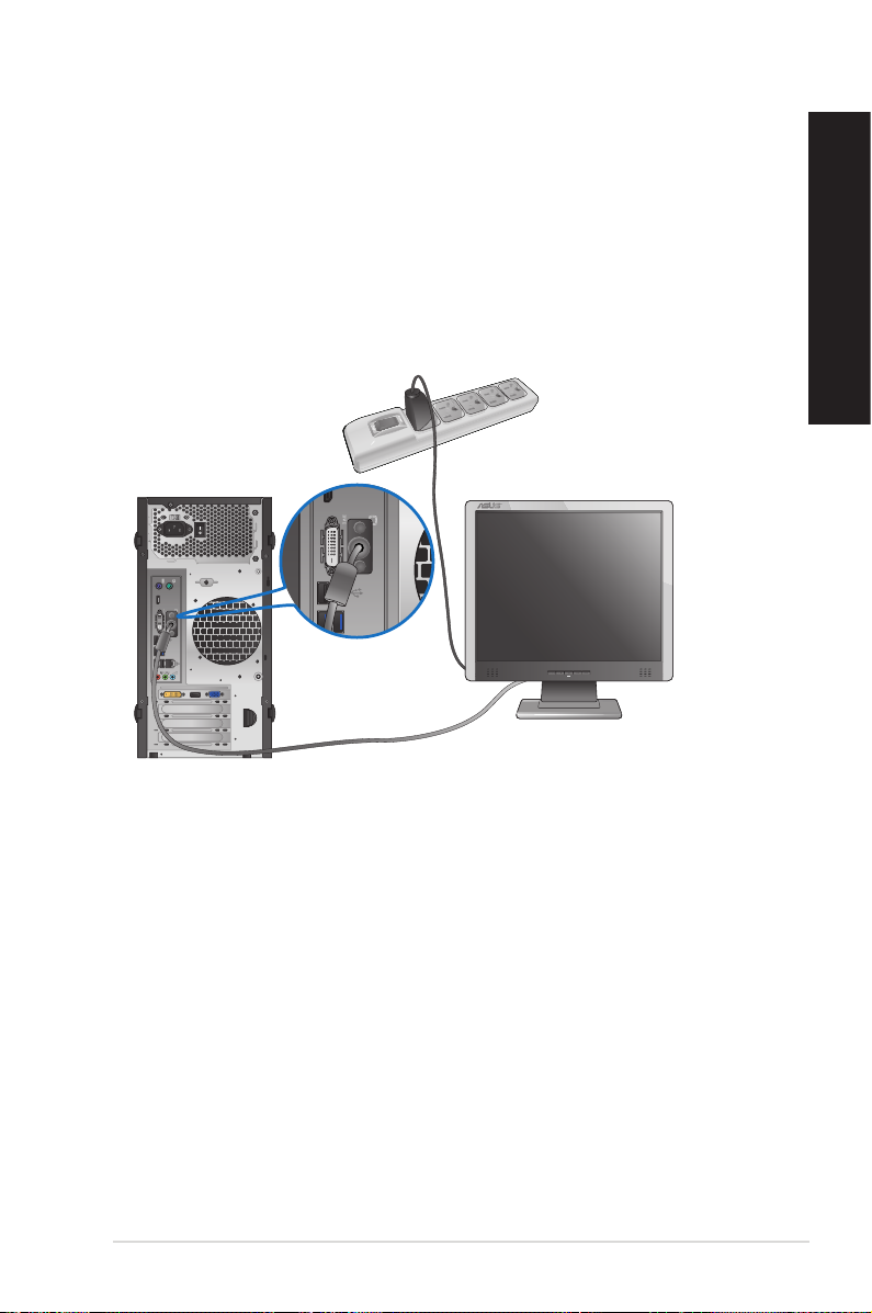
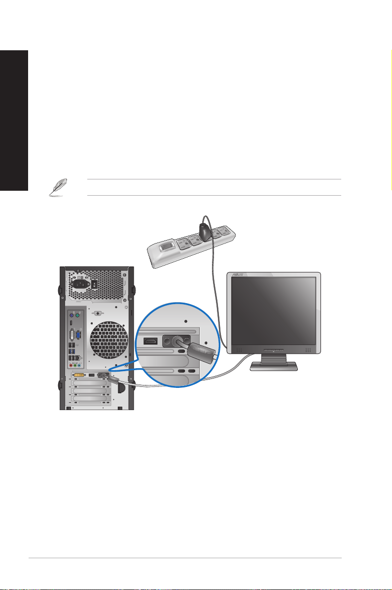
Using the onboard display output ports
Connect your monitor to the onboard display output port.
To connect an external monitor using the onboard display output ports:
1. Connect your monitor to the VGA port, DVI-D port, or display port of your computer.
2. Plug your monitor to a power source.
BM6660/MD710 and BM6360
ENGLISH
ASUS BM6660/MD710, BP6260/SD710, BM6360 1-11
ENGLISH
BP6260
• If your computer comes with an ASUS Graphics Card, the graphics card is set as the
primary display device in the BIOS. Hence, connect your monitor to a display output port
on the graphics card.
• To connect multiple external monitors to your computer, refer to Connecting multiple
external monitors in Chapter 3 of this user manual for details.
1-12 Chapter 1: Getting started
 Loading...