

Page 1

p
p
e
A
A
ollo
ollo
UUsseerr’’ss
GGuuiid
d
e
47-060023-005
Page 2

47-060023-005
Table of Contents
Congratulations! ................................................................................................ 1
Step 1 – Know Your PC’s Operating System .................................................. 1
Step 2 – Determine Your Connection Settings ................................................ 2
Step 3 – Install the ADSL Modem Card .......................................................... 3
Step 4 – Install the Drivers and Make a Connection ...................................... 5
Windows 95A ...................................................................................................... 6
Windows 95B ...................................................................................................... 9
Windows 98, 98SE ............................................................................................ 12
Windows Millennium ........................................................................................ 14
Windows NT4.0 - RFC1483 or RFC1577 ......................................................... 21
Windows NT4.0 - RFC2364 or RFC2516 ......................................................... 23
Windows 2000 ................................................................................................... 29
Windows XP...................................................................................................... 36
Appendix
Standard Utility.................................................................................................. 41
Un-Installer ............................................................................................... 41
Diagnostic Tools ....................................................................................... 43
XP Utility (for Windows XP only) .................................................................... 44
Un-installer ............................................................................................... 45
Diagnostic Tools ....................................................................................... 46
Connection Guide .............................................................................................. 51
Common Problems and Solutions...................................................................... 53
Connector & Jumper-pin Configuration Guide.................................................. 55
System Requirements & Compliance Information ............................................ 56
Copyright & Regulatory Information ................................................................ 56
Safety Instructions ............................................................................................. 56
FCC Statement................................................................................................... 57
User License Agreement.................................................................................... 58
Apollo ADSL Modem
Page 3

47-060023-004
Apollo ADSL Modem
1
Page 4
47-060023-005
Congratulations!
You are about to accelerate into ADSL technology. Your
new ADSL modem card is an internal Asymmetric Digital
Subscriber Line (ADSL) PCI modem card, which
conveniently plugs into your computer system. The modem
connects directly to your telephone line via a standard
connector.
This guide is designed to walk you through installation of
your ADSL Modem card in the easiest and quickest way possible. Please follow the
instructions carefully.
Step 1 – Know Your PC’s Operating System
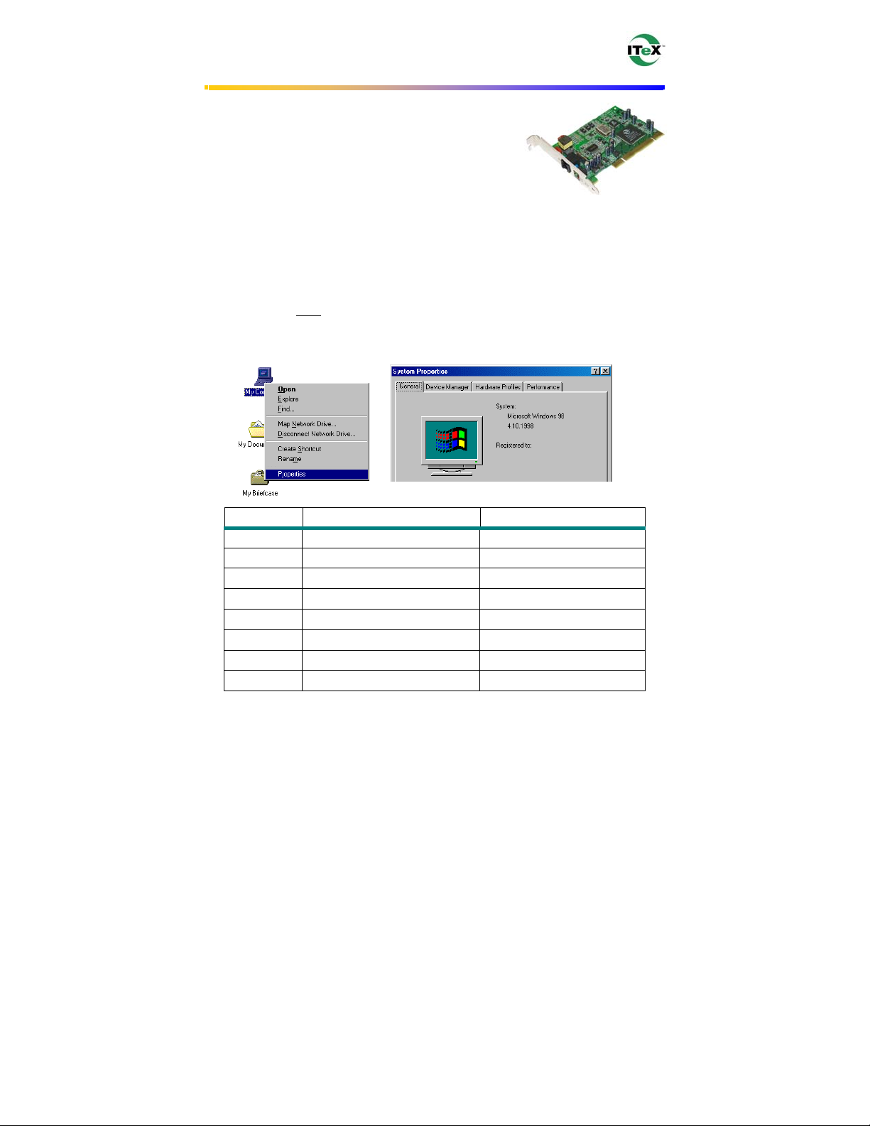
You will need to know the exact version of Microsoft Windows installed in your
computer. If you do not know or are unsure, please proceed as follows to determine your
version of the Microsoft Operating System.
On your desktop, right-click on My Computer, and select Properties. The version
number of the Microsoft Windows Operating System installed in your computer will be
displayed on the General tab. Refer to the following table for more detailed information.
Windows OS System Properties Description Release (Microsoft Web)
Win 95A 4.00.950A Windows 95 OSR1
Win 95B 4.00.950B Windows 95 OSR2
Win 98 4.10.1998 Window 98
Win 98SE 4.10.2222A Windows 98 2nd Edition
Win Me 4.90.3000 Windows Millennium
Win NT 4.00.1381 Windows NT 4.0
Win 2000 5.00.2195 Windows 2000
Win XP Version 2002 Windows XP
If you have questions regarding your PC system and the Microsoft Windows Operating
System, please contact your original PC manufacturer or Microsoft for assistance.
Before installing the ADSL PCI Modem Card, it is important to verify that the ADSL
data port RJ-11 jack is configured so that the center two pins, pins 3 and 4, are used for
ADSL data. If the ADSL data port installation uses pins 2 and 5 for data, consult the
Connector & Jumper-pin Configuration Guide located in the Appendix.
Apollo ADSL Modem
1
Page 5

47-060023-005
Step 2 – Determine Your Connection Settings
You need to know your PC system’s Windows OS and Internet Protocol supplied by
your ADSL service provider. Refer to the following chart for your ADSL Driver.
RFC1483
RFC1577
RFC2364
RFC2516
ADSL Driver Selection RFC1483 RFC1577 RFC2364 RFC2516
Win 95A & 95B 1483w95 1577w95 2364w95 2516w95
Win 98 & 98SE 1483w98 1577w98 2364w98 2516w98
Win 2000 1483w2K 1577w2K 2364w2K 2516w2K
Windows Millennium 1483wMe 1577wMe 2364wMe 2516wMe
Win NT 4.0 1483wNT 1577wNT 2364wNT 2516wNT
Win XP 1483wXP 1577wXP 2364wXP 2516wXP
Having determined the ADSL Driver you will be installing, you now need to gather the
connection information supplied by your ADSL service provider.
VPI value: _________
VCI value: _________
Framing: VC/MUX LLC/SNAP
Mode:
For
Host: User Name:
Domain: Password:
Gateway: Host or IP Address:
IP Address:
Subnet Mask:
DNS or server address:
ANSI T1.413 ITU G.lite ITU G.dmt
RFC1483 or RFC1577 For RFC2364 or RFC2516
Protocol Selection
Bridged Ethernet over ATM
Classical Internet Protocol over ATM
Point-to-Point Protocol over ATM
Point-to-Point Protocol over Ethernet
Apollo ADSL Modem
2
Page 6

47-060023-005
Step 3 – Install the ADSL Modem Card
Caution: To avoid possible damage to your modem card, touch the metal chassis of your
PC system to remove any static charge that may exist from your fingers, and then remove
your ADSL modem card from the protective anti-static bag.
1. Shut down your computer and
switch the power off.
2. Unplug the power cord for your
computer from the electrical
outlet.
3. Remove the cover from your
systems chassis (see your PC
manufacturer’s manual).
4. Unscrew “metal slot cover
bracket” from an unused PC
motherboard PCI connector (a
PCI connector is usually white
in color).
Apollo ADSL Modem
3
Page 7

47-060023-005
5. Gently and evenly insert the
PCI modem card into your
empty PCI slot.
6. Make sure the card is firmly
seated, and then secure the card
with the bracket screw.
7. Replace the cover of your
computer system and connect
your ADSL phone line to the
connector port on the modem
card. Then plug the other end of
the cable into your ADSL -phone
service.
Apollo ADSL Modem
4
Page 8

47-060023-005
Step 4 – Install the Drivers and Make a Connection
You will be installing drivers and then proceeding to make an Internet connection. This
process requires you to enter information as prompted by the Microsoft Installation
Wizard.
NOTE: You may need the Microsoft Windows Operating System installation files (CAB
files) to complete the installation. The CAB files are contained in the Microsoft’s system
CD-ROM. Some systems may have already installed the CAB files to the hard drive, but
you should have the Microsoft Windows CD-ROM handy just in case.
Proceed now to the installation procedure for the Windows Operating
System installed in your computer.
Windows 95A...................................................................................................... 6
Windows 95B...................................................................................................... 9
Windows 98, 98SE............................................................................................ 12
Windows Millennium....................................................................................... 14
Windows NT – RFC1483 and RFC1577 ........................................................ 21
Windows NT – RFC2364 and RFC2516 ........................................................ 23
Windows 2000 .................................................................................................. 29
Windows XP ..................................................................................................... 36
Apollo ADSL Modem
5
Page 9

47-060023-005
Windows 95A
After installing the ADSL modem card, plug the power cable back into the PC system
and turn the power on.
Before you proceed to install drivers, you may need to upgrade your Dial-Up Networking
(DUN) application to version 1.3 or above. The Microsoft DUN is conveniently
contained on your ADSL Driver CD-ROM.
1. After restart, the New Hardware Found
window will detect the ADSL modem as a
PCI Network Controller. At this time,
CANCEL the New hardware found
window.
2. At your desktop, click Start, and then
select Run.
3. The Run window appears. Click on
Browse and locate the drive that contains
your ADSL CD-ROM. Then locate and
select the MSDUN13.EXE file. The
MSDUN13.EXE appears in the Open box.
Click OK.
4. The Microsoft Dial-Up Networking 1.3
window appears with the message This
will install Microsoft Dial-Up
Networking 1.3 for Windows 95. Do you
wish to continue? Click Yes.
5. An End-User License Agreement will
appear. To accept, click Yes.
6. Again in the Microsoft Dial-Up
Networking 1.3 window, you will be
asked: Do you want to restart your
computer now? Click Yes.
Apollo ADSL Modem
6
Page 10
47-060023-005
NOTE: You may need the Microsoft Windows Operating System installation files (CAB
files) to complete the installation. The CAB files are contained in the Microsoft’s system
CD-ROM. Some systems may have already installed the CAB files to the hard drive, but
you should have the CD-ROM handy just in case.
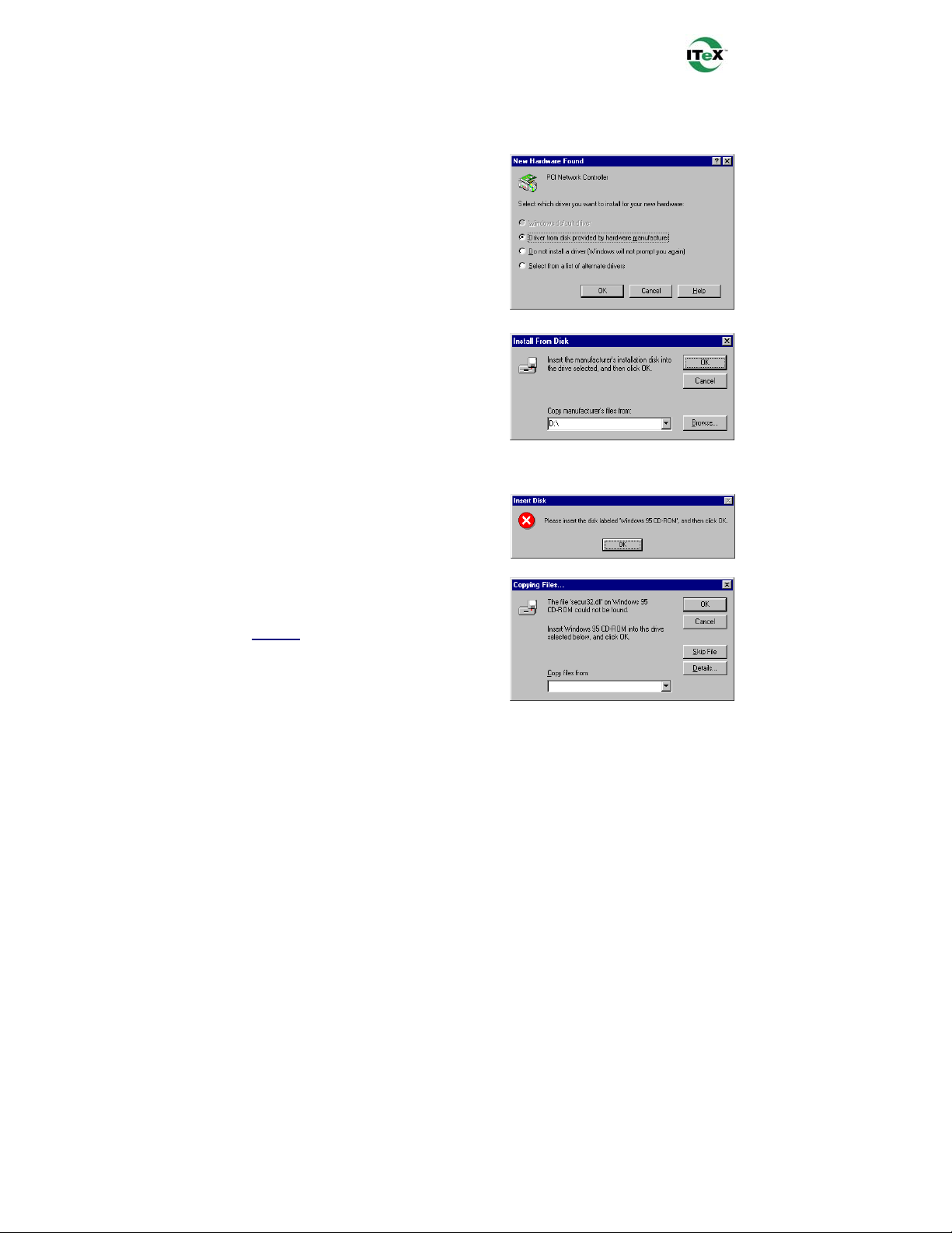
7. The New Hardware Found window will
again detect the ADSL modem card as a
PCI Network Controller. This time,
select the Driver from disk provided by
hardware manufacturer option. Click
OK.
Insert the ADSL Driver CD-ROM into your
systems CD drive now.
8. The Install From Disk window appears.
Click Browse to locate the driver on your
CD-ROM for the protocol supported by
your ADSL provider: 1483w95,
1577w95, 2516w95 or 2364w95. (The
example uses “D” as the CD-ROM drive
letter. Your drive letter may differ.) Then
click OK.
NOTE: During the installation process
you may be asked to insert your
Windows 95 CD. Insert the Windows 95
CD into the CD drive and click OK.
NOTE: If during the file copying process
a file is reported as “not found” enter the
path with the CD Drive letter and
:\Win95
(Ex: D:\Win95).
Apollo ADSL Modem
7
Page 11

47-060023-005
10. At the conclusion of the ADSL modem
driver installation, the Add New
Hardware Wizard window appears and
displays your newly installed ITeX
ADSL PCI NIC software. Click Finish.
11. The System Settings Change window
appears. For the PC system to set up the
ITeX ADSL PCI NIC, a system Restart is
required. Click Yes.
NOTE: After restarting the system, the
Diagnostic Tool icon (See Appendix) is
active and monitoring connectivity.
12. You must now set the ADSL Configuration. Go to page 15.
Apollo ADSL Modem
8
Page 12

47-060023-005
Windows 95B
After installing the ADSL modem card, plug the power cable back into the PC system
and turn the power on. Before you proceed to install the driver you may need to upgrade
your Dial-Up Networking (DUN) application to version 1.3 or above. The Microsoft
DUN is conveniently contained on your ADSL Driver CD-ROM.
1. After restart, the Update Device Driver
Wizard will detect the ADSL modem card
as a PCI Network Controller. At this
time, CANCEL the Update Device Driver
Wizard window.
2. At your desktop, click Start, and then
select Run.
3. The Run window appears. Click on
Browse and locate the drive that contains
your ADSL CD-ROM. Then locate and
select the MSDUN13.EXE file. The
MSDUN13.EXE then appears in the Open
box. Click OK.
4. The Microsoft Dial-Up Networking 1.3
window appears with the message This
will install Microsoft Dial-Up
Networking 1.3 for Windows 95. Do you
wish to continue? Click Yes.
5. An End-User License Agreement will
appear. To accept, click Yes.
6. Again back in the Microsoft Dial-Up
Networking 1.3 window, you will be
asked Do you want to restart your
computer now? Click Yes.
Apollo ADSL Modem
9
Page 13

47-060023-005
NOTE: You may need the Microsoft Windows Operating System installation files (CAB
files) to complete the installation. The CAB files are contained in the Microsoft’s system
CD-ROM. Some systems may have already installed the CAB files to the hard drive, but
you should have the CD-ROM handy just in case.
7. The Update Device Driver Wizard will
again detect the ADSL modem card as a
PCI Network Controller, click Next.
Insert the ADSL Driver CD-ROM into
your systems CD drive now.
8. The Update Device Driver Wizard will
appear and indicate that Windows was
unable to locate a driver for this device.
Click Other Locations.
9. The Select Other Location window
appears. Click Browse to locate the driver
on your CD-ROM for the protocol
supported by your ADSL provider:
1483w95, 1577w95, 2364w95 or
2516w95. (The example uses “E” as the
CD-ROM drive letter. Your drive may
have a different letter.) Then click OK.
10. The Update Device Driver Wizard will
then find the ITeX ADSL PCI NIC.
Click Finish.
NOTE: During the installation process
you may be asked to insert your Windows
95 CD-ROM. Insert the CD-ROM into
the drive. Click OK.
Apollo ADSL Modem
10
Page 14

47-060023-005
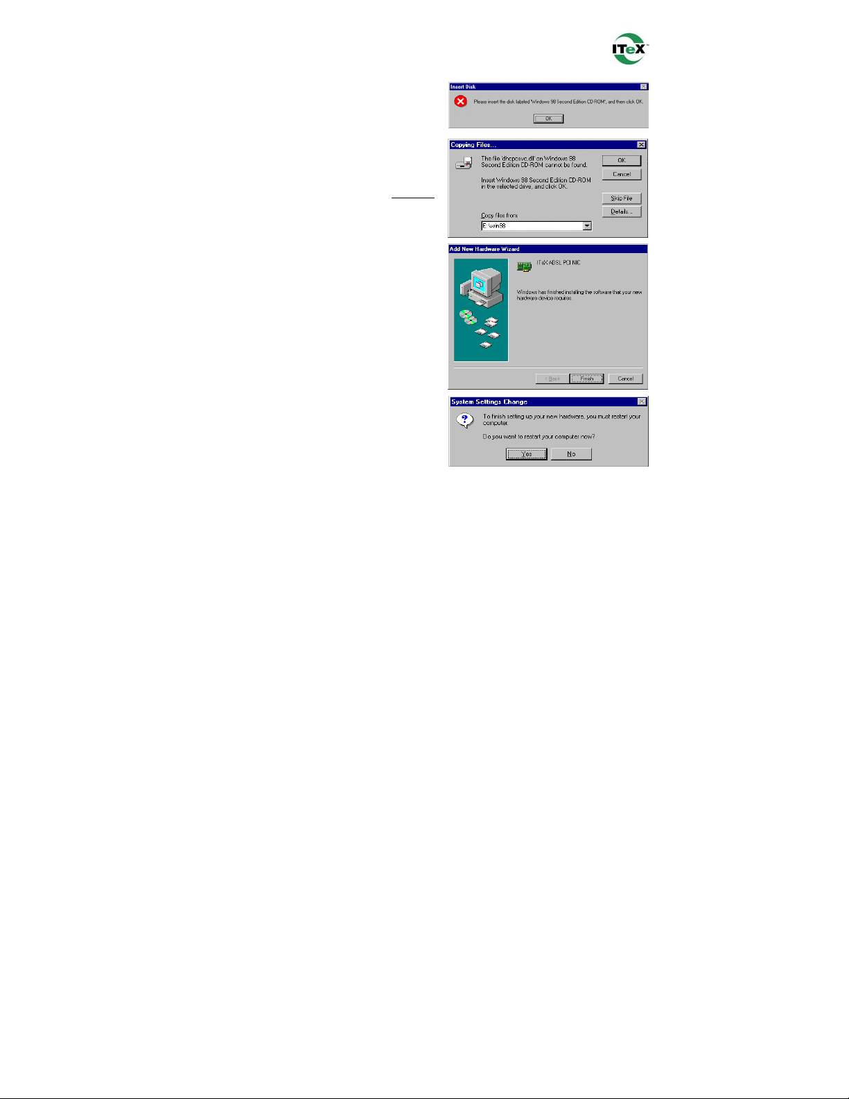
NOTE: If during the file copying process
a file is reported as not found, enter the
path (this example uses “E” as the CDROM drive letter, your drive letter may
differ) and: \Win95
(Ex: E:\Win95).
12. At the conclusion of the ADSL modem
driver installation, the Add New
Hardware Wizard window appears and
displays your newly installed ITeX
ADSL PCI NIC software. Click Finish.
13. The System Settings Change window
appears. For the PC system to set up the
ITeX ADSL PCI NIC driver, a system
Restart is required. Click Yes.
NOTE: After restarting the system, the
Diagnostic Tool icon (See Appendix) is
active and monitoring connectivity.
14. You must now set the ADSL Configuration. Go to page 15.
Apollo ADSL Modem
11
Page 15

47-060023-005
Windows 98, 98SE
After installing the ADSL modem card, plug the power cable back into the PC system
and turn the power on.
1. The Add New Hardware Wizard window
will automatically appear to indicate that a
new PCI Network Controller has been
found. Click Next.
Insert the ADSL Driver CD-ROM into your
systems CD-ROM drive now.
2. Still in the Add New Hardware Wizard,
you will be asked What do you want
Windows to do? Select the Search for the
best driver for your device option, then
click Next.
3. Select Specify a location and click Browse
to locate the driver on your CD-ROM for
the protocol supported by your ADSL
provider: 1483w98, 1577w98, 2364w98 or
2516w98. Click Next.
4. The Add New Hardware Wizard will
appear and indicate the ITeX ADSL PCI
NIC has been recognized and will install a
new driver. Click Next.
Apollo ADSL Modem
12
Page 16
47-060023-005
5. If prompted to insert your Windows CD,
do so at this time, then click OK.
6. Enter the CD drive letter (the example uses
“E” as the CD-ROM drive letter, your
drive letter may differ) and then :\Win98
(Ex: E:\Win98) and click OK.
7. At the conclusion of the ADSL modem
driver installation, the Add New
Hardware Wizard window appears again
and displays your newly installed ITeX
ADSL PCI NIC software. Click Finish
8. The System Settings Change window
appears. For the PC system to set up the
ITeX ADSL PCI NIC driver, a system
Restart is required. Click Yes.
NOTE: After restarting the system, the
Diagnostic Tool icon (See Appendix) is
active and monitoring connectivity.
9. You must now set the ADSL configuration. Go to page 15.
Apollo ADSL Modem
13
Page 17

47-060023-005
Windows Millennium
NOTE: After installing the ADSL modem card, plug the power cable back into the PC
system and turn the power on.
1. The Add New Hardware Wizard window
will automatically appear to indicate that a
new PCI Network Controller has been
found. Select the Specify the location of
the driver option. Click Next.
Insert the ADSL Driver CD-ROM into your
systems CD-ROM drive now.
2. Still in the Add New Hardware Wizard,
click the scroll arrow to locate the driver on
your CD-ROM for the protocol supported
by your ADSL provider: 1483wMe,
1577wMe, 2364wMe or 2516wMe. (The
example uses “D” as the CD-ROM drive
letter. Drive letters may vary.) Then click
Next.
3. The Add New Hardware Wizard has now
finished installing the new hardware
device. Click Finish
4. The System Setting Change window
appears. Click Yes to restart your PC
system to allow the new changes to take
effect.
5. You must now set the ADSL configuration. Go to page 15.
Apollo ADSL Modem
14
Page 18
47-060023-005
Setting the ADSL Configuration Win95, Win98, WinMe
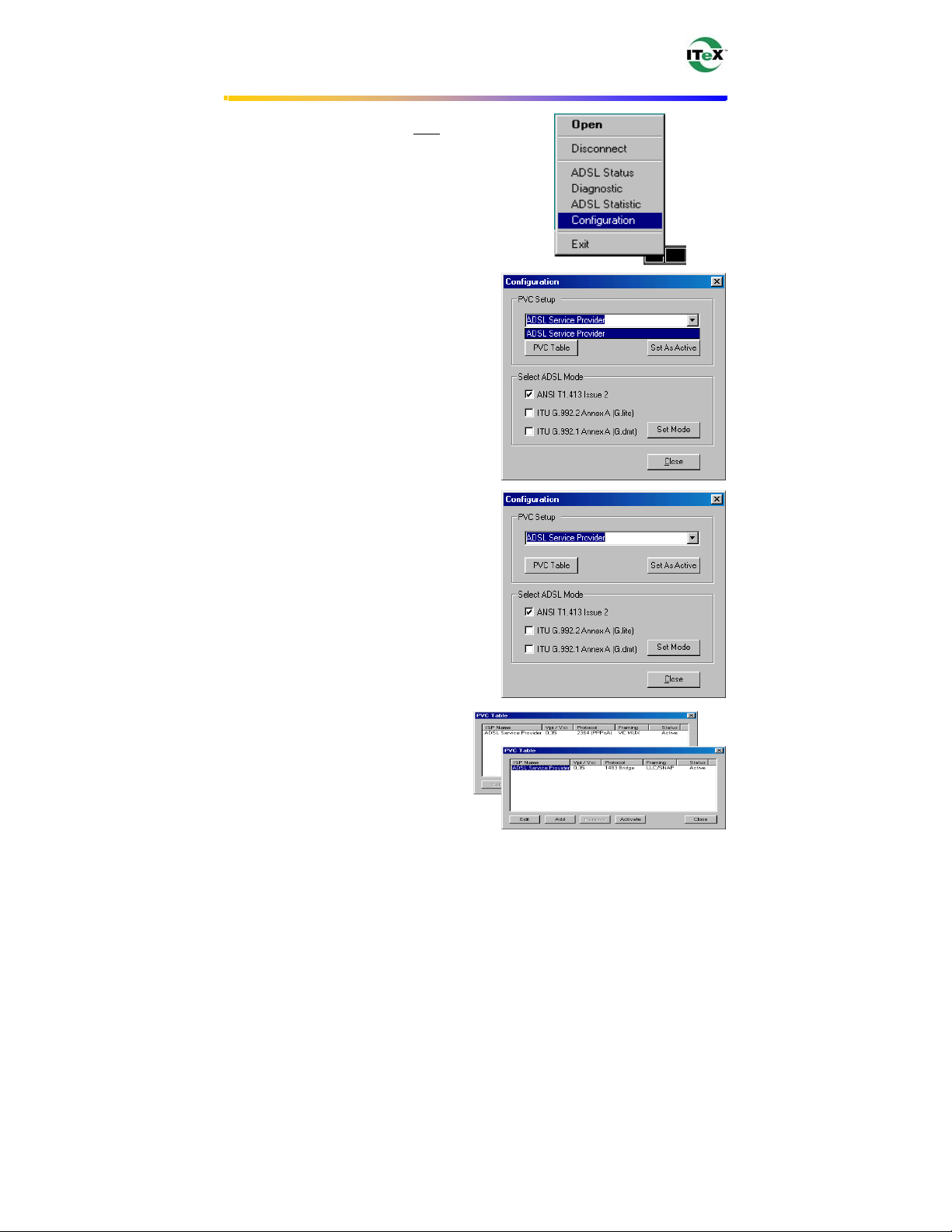
After your PC has rebooted, right-click on
1.
the Diagnostic Tool Icon (see Appendix),
and select the Configuration option.
2. When the Configuration window appears,
scroll through the PVC setup section to
locate the service you will be connecting
to. Then click Set As Active.
3. In the Select ADSL Mode section,
select the mode(s) recommended by
your ADSL service provider. Then
click Set Mode.
4. When you have set both the PVC
Setup and ADSL Mode, click Close.
NOTE: To modify, add, or remove ISP
settings from the Configuration
window, in the PVC Setup section,
click on the PVC Table button. The
PVC Table window then appears for
the Protocol you are using.
Apollo ADSL Modem
15
Page 19

47-060023-005
5. The PVC Setup window appears. Click
Yes to restart your PC system and to
allow the new changes to take effect.
6. You must now make an ADSL connection, proceed to the section for the protocol
you are using as follows:
RFC1483 and RFC1577 Go to page 17.
RFC2364 and RFC2516 Go to page 20.
Apollo ADSL Modem
16
Page 20

47-060023-005
Making an ADSL connection
RFC1483 or RFC1577 - Win95, Win98, WinMe
1. From the Start menu on the tool bar, select
Settings, Control Panel, and then double-
click on the Network icon.
2. The Network window appears. Select the
component window and verify that ITeX
ADSL PCI NIC is present.
3. Scroll the installed network component
window and select TCP/IP ITeX ADSL
PCI NIC. Then click the Properties
button.
Apollo ADSL Modem
17
Page 21

47-060023-005
4. The TCP/IP Properties window will
appear. Select the IP Address tab and then
select the Specify an IP Address option.
Enter the IP Address and Subnet Mask
settings supplied by your ADSL provider.
5. To setup a new gateway, select the
Gateway tab, and then enter the setting in
the New Gateway section. Click Add.
Apollo ADSL Modem
18
Page 22

47-060023-005
6. Select the DNS Configuration tab. Select
the Enable DNS option.
NOTE: You now need to have available the
Host, Domain and DNS settings supplied
by your ADSL service provider.
7. Enter your host name into Host: box.
8. Enter your domain name into Domain: box.
9. Enter DNS number into DNS Server
Search Order box and click Add. If you
have more than one DNS number, repeat
this step.
10. After setting all the necessary TCP/IP
properties, click OK.
11. The Network window appears (not shown).
Click OK.
12. The System Setting Change window
appears. You will be asked if you want to
restart your computer. Click Yes.
Congratulations, you are done. Your ADSL Internet connection is established!
Apollo ADSL Modem
19
Page 23

47-060023-005
Making an ADSL Connection
RFC2364 or RFC2516 – Win95, Win98, WinMe
1. After your PC restarts, the Location
Information window may appear (See
NOTE below). Enter the area code and
phone number given to you by your
ADSL service provider.
NOTE: This screen may not appear on
Windows operating systems 95 or 98.
2. Double
-click on the ADSL Connect
icon that appears on your desktop.
3. The Connect To window appears. Enter
the User Name, Password and Phone
number supplied by your Internet
service provider (ISP). Then click
Connect.
4. The Connecting to My Connection
window appears. The message Logging
on to network confirms a valid
connecting process.
5. The Connection Established window
appears. Internet service is now
established. Click Close and then the
Diagnostic tool icon will appear on the
task bar.
ADSL Connect
Apollo ADSL Modem
20
Page 24

47-060023-005
Windows NT4.0 - RFC1483 or RFC1577
1. Right-Click on the Network
Neighborhood icon, and select
Properties.
2. The Network window appears. Select the
Adapters tab and then click Add.
Insert ADSL Driver CD-ROM into your
system’s CD drive now.
3. The Select Network Adapter window
appears. Click Have Disk.
4. The Insert Disk window appears. In the
driver folder location, type in the protocol
supported by your ADSL provider: Ex.
1483wNT or 1577wNT. (The example
uses “d” as the CD-ROM drive letter.
Your drive may have a different letter.)
Click OK.
5. The Select OEM Option window will
find ITeX ADSL PCI NIC. Click OK.
Apollo ADSL Modem
21
Page 25

47-060023-005
6. The Network window will appear.
Click the Adapters tab to verify that
ITeX ADSL PCI NIC has been found.
Click on the Protocols tab and verify
that ADSL Management and Monitor
Interface is present. When you have
verified these items, click Close.
NOTE: To review the Network window
properties at any time, right
Network Neighborhood icon and select
Properties.
7. The Microsoft TCP/IP Properties
window appears. Select Specify an IP
address. Enter in the IP Address,
Subnet Mask, and Default Gateway
supplied by your ADSL service
provider. Click OK.
8. The Network Settings Change
window appears. You must now re-start
your computer for the settings to take
effect. Click Yes.
9.
You must now set the ADSL configuration. Go to page 26.
-click the
Apollo ADSL Modem
22
Page 26

47-060023-005
Windows NT4.0 - RFC2364 and RFC2516
1. Right-click on the Network
Neighborhood icon, and select
Properties.
2. The Network window appears. Select the
Adapters tab and then click Add.
Insert the ADSL Driver CD-ROM into your
system’s CD drive now
3. The Select Network Adapter window
appears. Click Have Disk.
4. The Insert Disk window appears. In the
driver folder location, type in the protocol
supported by your ADSL provider:
2364wNT or 2516wNT. (The example
uses “d” as the CD-ROM drive letter.
Your drive may have a different letter.)
Click OK.
5. The Select OEM Option window will
find ITeX ADSL PCI NIC. Click OK.
Apollo ADSL Modem
23
Page 27

47-060023-005
6. The Setup Message window appears.
Click OK.
7. The Windows NT Setup window
appears. Insert your NT4.0 CD-ROM into
the PC system CD drive, and type in
“D:\i386”. Click Continue.
8. The Remote Access Setup window
appears. Click Add.
9. The Add RAS Device window appears.
Scroll to locate and select IDSN1-
itexwana. Then Click OK.
10. The Remote Access Setup window
appears. Click Continue.
Apollo ADSL Modem
24
Page 28

47-060023-005
11. The Network window will appear. Click
the Adapters tab to verify that ITeX
ADSL PCI NIC has been found. Click on
the Protocols tab and verify that the ADSL
Management and Monitor Interface is
present. Then click Close.
NOTE: To review the Network window
properties at any time, right-click the
Network
Properties.
12. The Network Settings Change window
appears. You must now re-start your
computer for the settings to take effect.
Click Yes.
13. You must now set the ADSL configuration. Go to page 26.
Neighborhood icon and select
Apollo ADSL Modem
25
Page 29

47-060023-005
Setting the ADSL Configuration – Win NT4.0
1. After your PC has rebooted, right-click on
the Diagnostic Tool Icon (see Appendix),
and select the Configuration option.
2. When the Configuration window appears,
scroll through the PVC setup section to
locate the service you will be connecting
to. Then click Set as Active.
3. In the Select ADSL Mode section, select
the mode(s) recommended by you ADSL
service provider. Then click Set Mode.
4. When you have set both the PVC Setup
and ADSL Mode, click Close.
NOTE: To modify, add, or remove
ISP settings from the Configuration
window, in the PVC Setup section,
click on the PVC Table button. The
PVC Table window then appears for
the Protocol you are using.
Apollo ADSL Modem
26
Page 30

47-060023-005
5. The PVC Setup window appears. Click
Yes to restart your PC system and to
allow the new changes to take effect.
6. You must now make an ADSL connection. Go to page 28.
Apollo ADSL Modem
27
Page 31

47-060023-005
Windows NT4.0
Creating a Dial-up Network Connection
1. Double-click on the ADSL Connect icon
that appears on your desktop.
2. The Dial-Up Networking window appears
and prompts for the phone number of the
dial-up server. Unless instructed to enter a
phone number by the ADSL service
provider, enter zero “0”. Click Dial.
3. The Connect to MyDialUpServer
window appears. Enter the User name,
Password and Domain supplied by your
ADSL service provider. Click OK.
Note: If this screen persists and a
connection logon error is reported,
confirm that the correct User name and
Password are entered and try the
connection again. Also verify that the
connection address is correct.
4. The Connection Complete window is
displayed at the completion of a
successful Dial-Up logon. Choose a
display behavior and click OK to close.
Congratulations, you are done. Your ADSL connection is established!
ADSL Connect
Apollo ADSL Modem
28
Page 32

47-060023-005
Windows 2000
After installing the ADSL modem card, plug the power cable back into the PC system
and turn the power on.
1. After installing the ADSL modem card,
power on the PC system. After start-up, the
Found New Hardware Wizard will
appear. Click Next.
Insert the ADSL Driver CD-ROM into your
system’s CD drive now
2. Still in the Found New Hardware
Wizard, select the Search for a suitable
driver for my device option. Click Next.
3. Next you will be prompted for software
drivers. Select Specify a location. Click
Next.
4. Click Browse to locate the driver on your
CD-ROM for the protocol supported by
your ADSL provider: 1483w2K,
1577w2K, 2364w2K or 2516w2K. (The
example uses “D” as the CD-ROM drive
letter. Your drive may have a different
letter.) Click OK
Apollo ADSL Modem
29
Page 33

47-060023-005
5. The Found New Hardware Wizard will
then display the driver you selected, click
Next.
6. The Digital Signature Not Found window
appears, and shows ITeX ADSL PCI NIC.
You will be asked; Do you want to
continue installation? Click Yes.
7. The Found New Hardware Wizard will
prompt that Windows has finished
installing the software for this device.
Click Finish.
NOTE: You may be asked if you want to
restart your computer, if so click Yes. If
you are not asked, you need to restart your
computer manually at this time.
8. You must now set the ADSL configuration. Go to page 31.
Apollo ADSL Modem
30
Page 34

47-060023-005
Setting the ADSL Configuration – Win 2000
1. After your PC has rebooted, right
the Diagnostic Tool Icon (see Appendix),
and select the Configuration option.
-click on
2. When the Configuration window appears,
scroll through the PVC setup section to
locate the service you will be connecting to.
Then click Set As Active.
3. In the Select ADSL Mode section, select
the mode(s) recommended by you ADSL
service provider. Then click Set Mode.
4. When you have set both the PVC Setup
and ADSL Mode, click Close.
NOTE: To modify, add, or remove
ISP settings from the Configuration
window, in the PVC Setup section,
click on the PVC Table button. The
PVC Table window then appears for
the Protocol you are using.
Apollo ADSL Modem
31
Page 35

47-060023-005
5. The PVC Setup window appears. Click
Yes to restart your PC system and to allow
the new changes to take effect.
6. You must now make an ADSL connection, proceed to the section for the protocol
you are using as follows:
RFC1483 or RFC1577 Go to page 33.
RFC2364 or RFC2516 Go to page 35.
Apollo ADSL Modem
32
Page 36

47-060023-005
Making an ADSL Connection - RFC1483 or RFC1577
1. Right – click My Network Places and
select Properties.
2. The Network and Dial-up Connections
window appears. Right
Area Connection, and then click on
Properties.
-click on the Local
3. The Local Area Connection Properties
window appears. Click on Internet
Protocol (TCP/IP), then click on
Properties.
Apollo ADSL Modem
33
Page 37

47-060023-005
4. The Internet Protocol (TCP/IP)
Properties window appears. Under the
General tab, enable Use the following IP
address. The default settings for IP
configurations will turn from gray to
white. Enter in the IP address, Subnet
Mask, and Default Gateway supplied by
your ADSL service provider. Click OK.
5. The previous General Tab window
appears. Click OK.
6. The Network and Dial-up Connections
window appears. Close this window and
your connection is complete.
Congratulations, you are done. Your ADSL Internet connection is established!
Apollo ADSL Modem
34
Page 38

47-060023-005
Making an ADSL Connection - RFC2364 or RFC2516
1. Double-click on the ADSL Connect icon
that appears on your desktop.
ADSL Connect
2. The Connect My connection window
will appear. Enter your User Name,
Password and Phone Number supplied
by your ADSL service provider. You are
now ready to make a network connection.
Click Dial.
3. The Connection complete window
appears, click OK.
Congratulations, you are done. Your ADSL connection is established!
Apollo ADSL Modem
35
Page 39

47-060023-005
Windows XP
After installing the ADSL modem card, plug the power cable back into the PC system
and turn the power on.
Insert the ADSL Driver CD-ROM into your
system’s CD drive now
1. Upon your system’s reboot, the Found
New Hardware Wizard appears. Click
Next.
2. Select the correct protocol, for Windows
XP, given to you by your ADSL service
provider. Click Next.
A Microsoft window may appear at this time.
Click “Continue Anyway”.
3. Completing the Found New Hardware
Wizard appears. Click Next to complete
the installation of your ITeX Apollo
Modem.
4. You must now set the ADSL configuration.
Go to page 37.
Apollo ADSL Modem
36
Page 40

47-060023-005
Setting the ADSL Configuration – Windows XP
1. Right
-click on the Diagnostic Tool Icon
(see Appendix), and select
Configuration.
2. When the Configuration window
appears, scroll through the PVC setup
section to locate the service you will be
connecting to. Then click Set As Active.
3. In the Select ADSL Mode section, select
the mode(s) recommended by you ADSL
service provider. Then click Set Mode.
4. When you have set both the PVC Setup
and ADSL Mode, click Close.
NOTE: To modify, add, or remove ISP
settings from the Configuration
window, in the PVC Setup section,
click on the PVC Table button. The
PVC Table window then appears for
the Protocol you are using.
2364 PPPoA VC MUX
5. You must now make an ADSL connection, proceed to the section for the protocol
you are using as follows:
RFC1483 or RFC1577 Go to page 38.
RFC2364 or RFC2516 Go to page 40.
Apollo ADSL Modem
37
Page 41

47-060023-005
Making an ADSL Connection - RFC1483 or RFC1577
1. Right – click on My Network Places and
select Properties.
2. Right
– click the Local Area Connection
that contains the ITeX ADSL PCI NIC.
Select Properties.
3. The Local Area Connections Properties
window appears. Click Internet Protocol
(TCP/IP). Click Properties.
Apollo ADSL Modem
38
Page 42

47-060023-005
4. Select “Use the following IP address:”
Enter the IP Address, Subnet mask, and
Default gateway given to you by your
ADSL service provider.
5. After you have entered the information,
click OK and Close any remaining
connection windows.
Congratulations, you are done. Your ADSL connection is established!
Apollo ADSL Modem
39
Page 43

47-060023-005
Making a Connection - RFC2364 or RFC2516
1. Double – click the ADSL connection icon
that appears on the desktop.
2. Enter the User name, Password, and Dial-
up number given to you by your ADSL
service provider. Click Dial.
Congratulations, you are done. Your ADSL connection is established!
Apollo ADSL Modem
40
Page 44

47-060023-005
Standard ADSL Utility
Win 98, Win Me, Win 2000, Win NT 4.0
To access the ADSL Utility window:
1. Click on the Start menu and select Programs.
2. Select the ITeX option.
3. Four options appear if you have installed protocols RFC2364 or RFC2516: ADSL
Diagnostic Tools, Dial-Up Connection, Read Me, and Un-Installer (protocols
RFC1483 and RFC1577 display Diagnostic Tools, Read Me, and Un-installer
only).
Un-Installer – This option un-installs the modem from your PC. For the correct
instructions on how to use this utility, see the Standard Un-Installer section.
ADSL Diagnostic Tools – If, in the event you have deleted the Diagnostic Tools icon on
the taskbar, this option launches the Diagnostic Tools utility icon back onto the taskbar.
For the correct instructions on how to operate the Diagnostic Tools, see the Diagnostic
Tools section.
Read Me – The Read-Me file supplies more information about ITeX and the Apollo
driver.
Dial-Up Connection (RFC2364 and RFC2516 only) – If, in the event you have deleted
the Dial-up connection icon on your desktop, this option launches the Dial-Up connection
application.
Apollo ADSL Modem
41
Page 45

47-060023-005
Standard Un-Installer
Win 98, Win Me, Win 2000, Win NT 4.0
1. On the desktop, click the START Menu on the Task Bar.
2. Select Programs. The programs window appears.
3. Select the ITeX tab, and then click on the Un-Installer Tab.
A Warning window appears. Click
4.
Yes to proceed.
5. The Uninstall Finished window
appears. Click Yes to restart your
computer and allow the changes to
take effect.
Apollo ADSL Modem
42
Page 46

47-060023-005
Standard Diagnostic Tools
Win 98, Win Me, Win 2000, Win NT 4.0
The Diagnostic Tool icon allows the user to monitor the ADSL connectivity and run
diagnostic tests. The Diagnostic Tool icon is displayed on the task bar as shown.
1. Right - click the ADSL modem diagnostic tool
icon, and then select Open.
The ADSL Diagnostic Tool window appears
on your desktop. The three tabs of the
Diagnostic Tool appear: ADSL Status,
Diagnostic, and ADSL Statistics.
The ADSL Status tab displays the current
status of the ADSL connection, including the
current ADSL State, ADSL Protocol in use,
and the Transmit/Receive Rate for upstream
and downstream data.
Apollo ADSL Modem
43
Page 47

47-060023-005
2. To run diagnostics click on the Diagnostic
tab. The blank Diagnostic window appears.
3.
Click Run Diagnostics to begin the
diagnostic test.
4. A Warning Message appears. Click Yes to
run the test and disconnect your modem.
Click No if you do not wish to disconnect
or run the test.
5. The Diagnostic Report appears with the
test results. All tests must “pass” for a
functional test of the Apollo modem card.
6. You may obtain driver information as well
by clicking the Product Info tab.
NOTE: To reconnect your modem right
the Diagnostic Tool icon on the task bar, and
select Connect.
- click
Apollo ADSL Modem
44
Page 48

47-060023-005
7. The ADSL Statistic tab provides you with
detailed information on your ADSL
modem connection.
Re-training Count tracks the number of
ADSL connections performed.
FEC Count tracks the forward error correction
count.
CRC Count tracks the number of CRC errors.
ATM HEC Count (Header Error Control)
errors are recorded as an indication of ATM
packet accuracy.
As a measure of packet transfer performance,
the ATM Receive Side and ATM
Transmission Side Statistics (Packet Errors)
are counted.
Apollo ADSL Modem
45
Page 49

47-060023-005
XP Utility
To access the ADSL Utility window:
1. Click on the Start menu and select All Programs.
2. Select the ITeX option.
3. Four options appear if you have installed protocols RFC2516 or RFC2364: ADSL
Diagnostic Tools, Dial-Up Connection, Read Me, and Un-Installer (protocols
RFC1483 and RFC1577 display Diagnostic Tools, Read Me, and Un-installer
only).
ADSL Diagnostic Tools – If, in the event you have deleted the Diagnostic Tools icon on
the taskbar, this option launches the Diagnostic Tools utility icon back onto the taskbar.
For the correct instructions on how to operate the Diagnostic Tools, see the XP
Diagnostic Tools section.
Dial-Up Connection (for RFC2364 or RFC2516 only)– In the event you have deleted
the Dial-up connection icon on your desktop, this option launches the Dial-up connection
application.
Read Me – The Read-Me file supplies more information about ITeX and the Apollo
driver.
Un-Installer - This option un-installs the modem from your PC. For the correct
instructions on how to use this utility, see the XP Un-Installer section.
Apollo ADSL Modem
46
Page 50

47-060023-005
XP Un-Installer
1. On the desktop, click the START Menu on
the Task Bar.
2. Select All Programs. The programs window
appears.
3. Select the ITeX tab, and then click on the
Un-Installer Tab.
4. A Warning message may appear. Click
Yes to un-install your Apollo modem and
allow the changes to take effect.
Apollo ADSL Modem
47
Page 51

47-060023-005
XP Diagnostic Tools
The Diagnostic Tool icon allows the user to monitor the ADSL connectivity and run
diagnostic tests. The Diagnostic Tool icon is displayed on the task bar as shown.
- click the ADSL modem diagnostic tool icon, and then select Open.
1. Right
The ADSL Diagnostic Tool window appears
on your desktop. The three tabs of the
Diagnostic Tool appear: ADSL Status,
Diagnostic, and ADSL Statistics.
The ADSL Status tab displays the current
status of the ADSL connection, including the
current ADSL State, ADSL Protocol in use,
and the Transmit/Receive Rate for upstream
and downstream data.
2. To run diagnostics click on the Diagnostic
tab. The blank Diagnostic window
appears.
3. Click Run Diagnostics to begin the
diagnostic test.
Apollo ADSL Modem
48
Page 52

47-060023-005
4. A Warning Message appears. Click Yes to
run the test and disconnect your modem.
Click No if you do not wish to disconnect
or run the test.
5. The Diagnostic Report appears with the
test results.
to disconnect or run the test.
6. You may obtain driver information as well
by clicking the Product Info tab.
Click No if you do not wish
NOTE: (to reconnect your modem right
the Diagnostic Tool icon on the task bar, and
select Connect).
click
Apollo ADSL Modem
49
Page 53

47-060023-005
7. The ADSL Statistic tab provides you with detailed information on your ADSL modem
connection.
Re-training Count tracks the number of
ADSL connections performed.
FEC Count tracks the forward error correction
count.
CRC Count tracks the number of CRC errors.
ATM HEC Count (Header Error Control)
errors are recorded as an indication of ATM
packet accuracy.
As a measure of packet transfer performance,
the ATM Receive Side and ATM
Transmission Side Statistics (Packet Errors)
are counted.
Apollo ADSL Modem
50
Page 54

47-060023-005
p
ADSL Connection Guide
The A in ADSL stands for Asymmetric.
Since most home users tend to be more of a
consumer of data than a producer, a slower
upstream (upload) speed can be traded off
for a faster downstream (download) speed.
ADSL is designed to run on your standard
telephone line or POTS (Plane Old
Telephone System) by squeezing the voice
band into the low end of the frequency
spectrum, and running the ADSL digital on
the high end of the frequency spectrum.
ADSL therefore needs a splitter to be placed
during installation to separate the two.
Line Splitter: A splitter is a small device that captures the first 4khz of frequency and
splits them off for phone use. The rest of the data is passed onto the ADSL equipment.
The splitter is the first device an ADSL line meets when it arrives at the user’s premises.
Splitters are usually employed at the time when ADSL lines are provisioned.
This diagram is of a basic ADSL in a home. The splitter depicted here is a small box that
strips off the phone signal from the line from the ADSL Service Provider, and leaves the
data (indicated by the orange line), to be routed to the data equipment, on RJ11 (phone)
inside wires.
S
litter
Internet Service Provider
Line Filter: A separate filter may be required if an ADSL setup does not use splitters.
For a splitter setup, the filter is built into the splitter. The filter is to protect the ADSL
signal from being contaminated by high frequency noise added by analog phone devices,
answering machines, faxes and so on. An ADSL setup, with a filter instead of a splitter,
allows the data and voice signal to flow through the house phone wires, but filters it from
the telephone or fax machines.
Internet Service
Provider
Apollo ADSL Modem
51
Page 55

47-060023-005
TIP: Radio frequency interference, such as a television or a cordless telephone
may effect you ADSL connection. If you have such a device close to the telephone line of
your computer, you should move the device.
NOTE: ADSL service may introduce audible interference on some phone
equipment.
Apollo ADSL Modem
52
Page 56

47-060023-005
Common Problems and Solutions
The Diagnostic Tool icon consists of two lights side by side. The left light indicates data
is being transmitted whereas the right
light indicates data is being received. Some
common problems with the connection can be determined as follows:
Color Code Description
Red, Red No ADSL connection or handshaking. Check your cable.
Black, Yellow Handshaking (flashing yellow alternating position).
Black, Black No data traffic or idle connection.
Black, Green Modem card is receiving data (TX/off, RX/on).
Green, Black Modem card is transmitting data (TX/on, RX/off).
Green, Green Modem card is transmitting and receiving data. (TX/on, RX/on).
Driver installation problem exists. Un-Install driver.
Problem
The ADSL modem
diagnostic icon is not
on the taskbar.
Restart the computer:
1. Save and close any open files and exit any open programs.
2. Click the Start button, and then click Shut Down.
3. In the Shut Down Windows window, click Restart and then
click OK.
If the ADSL modem diagnostic icon does not appear after you
restart the computer, uninstall and reinstall the driver.
Solution
There are 2 ADSL
modem diagnostic
icons on the taskbar.
The ADSL modem
diagnostic icon lights
are black and flashing
yellow:
Apollo ADSL Modem
You may have inadvertently installed the driver twice without
performing the ITeX Un-Installer procedure. Contact your ADSL
Internet service provider before you uninstall any ADSL modem
driver to ensure that you uninstall the appropriate driver.
The ADSL modem is trying to connect to the Internet. If the
modem fails to connect, ensure that the modem is connected to
the telephone wall jack.
You may have inadvertently or incorrectly installed a filter or line
conditioner on the telephone cord that connects the modem to
the telephone wall jack.
Your ADSL service may be temporarily down. Contact your
ADSL Internet service provider.
53
Page 57

47-060023-005
Both ADSL modem
diagnostic icon lights
are red.
You cannot connect to
the Internet.
You can connect to
the Internet but the
connection
unexpectedly
terminates.
You hear noise or
static when you use
the telephone.
Ensure that the modem is connected to the telephone line, and
that your telephone line is connected to the wall jack. Verify that
the ADSL Modes selected are ANSI and G.dmt.
Your ADSL service may be temporarily down. Contact your
ADSL Internet service provider.
Right-click the modem diagnostic icon and then click Diagnostic
to run the modem diagnostics.
If all tests pass, the digital circuit is functioning properly, but the
analog circuit may be defective. Contact your ADSL Internet
service provider.
If any of the tests fail, the digital circuit is defective. Contact your
ADSL Internet service provider.
There may be a problem with the PPPoE installation. The
service is configured for Static IP. Verify that the TCP/IP Entries,
gateway, and DNS are correct. Contact your ADSL service
provider for further assistance. Reboot the system and make a
new connection.
The telephone line that connects the ADSL modem to the
telephone wall jack may be too close to a device that emits
radio frequency interference, such as a television or a cordless
telephone. If you have such a device close to the telephone line
or your computer, try moving the device.
Contact your ADSL Internet service provider.
Ensure that you have installed the wall-mount filter or a line
conditioner.
A problem with the driver installation. Un-Install the drivers and
reload them.
Apollo ADSL Modem
54
Page 58

47-060023-005
Connector & Jumper-pin Configuration Guide
It is important to verify that the ADSL data port RJ-11 jack is configured so that the
center two pins, pins 3 and 4, are used for ADSL data. Otherwise, the ADSL PCI modem
card will not make a proper connection. Your ADSL modem card features pin jumpers
that enable the user to set the configuration to make the proper connection. The modem
card is default set to 3 and 4.
If the ADSL data port installation uses pins 2 and 5 for data, then the jumper settings on
your board will need to be reconfigured. To do this, orient your board per the diagram
below (the RJ-11 connector should be facing towards you) and simply lift the jumper off
of the pin setting for 3 and 4, and place it onto the pin setting for 2 and 5, or visa versa.
2
3
4
5
RJ-11 Jumper
3 & 4 1 & 2
2 & 5 2 & 3
Jumper (s) setting
for 3&4 data pins
3 2 1
ADSL Modem Card LED Indicators
LED Status Signal Description
Green Bottom
Green Top
Yellow Top
Red Bottom
All four
PWR Flashing
On
SYNC Flashing fast
Flashing slow
DATA On: TX or RX
Off: no data
ERR Flash on CRC error ATM data transmission
All On Driver not installed or
ADSL Modem Card Bracket
3 2 1
Initialized, idle mode (disconnect)
Power Supply OK
Modem Connecting
Modem Connected
ATM data transmission
modem card is defective
Apollo ADSL Modem
55
Page 59

47-060023-005
System Requirements & Compliance Certification
System Requirements
√ IBM PC/AT or compatible
√ Pentium 500Mhz or faster
√ 30Mbytes or more available hard disk space
√ 2x CD-ROM drive or better
√ 32Mbyte or more available system memory
Power Requirements
√ 0.75A Max @ +5V ± 5%, 0.1A max @ ± 12V, ± 5%
Environmental Requirements
√ Operating Temperature: 0 °C to 70°C with airflow
√ Non-operating Temperature: -10 °C to 85 °C
√ Operating Humidity: 10% to 90% non-condensing
√ Non-operating storage humidity: 5% to 95% non-condensing
Compliance Certification
√ UL 1950
√ CE approved
√ FCC Part 15 Class B
Copyright & Regulatory Information
Driver software and manual Copyright 2001, Integrated Telecom Express, Inc.
This manual and software described in it are copyrighted with all rights reserved. This
manual may not be copied, in whole or in part, without written consent. All product
names are trademarks and or registered trademarks of their respective companies.
Safety Instructions
Use the following instructions to help protect yourself and your computer.
• For use in UL – listed Personal Computers
• Caution – To reduce the risk of fire, use only No. 26 AWG or larger telecommunication line cord.
• Disconnect telecommunication line during an electrical storm to avoid the remote risk of electric shock from
lightning via the telephone line.
• To remove power from the computer, turn it off, and disconnect power cable from electrical outlet.
• To help avoid the potential hazard of electrical shock, do not connect or disconnect cable or perform
installation and un-installation of this product.
• Handle this product with care. Holding it by the metal bracket.
• Important Safety Instructions- When using your telephone equipment, basic safety precautions should be
always followed to reduce the risk of fire, electric shock and injury to persons, including the following:
1. Do not use this product near water. For example: near a bathtub, washbowl, kitchen sink or laundry tub,
in a wet basement, or near a swimming pool.
2. Avoid using a telephone (other than a cordless type) during an electrical storm. There may be a remote
risk of electric shock from lighting.
3. Do not use the telephone to report a gas leak in the vicinity of the leak.
4. Using only the telephone line cord indicated in this manual.
Apollo ADSL Modem
56
Page 60

47-060023-005
FCC Statement
FCC Part 15 Notice
WARNING: This equipment has been tested and found to comply with the limits for a Class B digital device,
pursuant to Part 15 of the FCC Rules. These limits are designed to provide reasonable protection against harmful
interference in a residential installation. This equipment generates, uses, and can radiate radio frequency energy
and, if not installed and used in accordance with the instructions, may cause harmful interference to radio
communications. However, there is no guarantee that interference will not occur in a particular installation. If this
equipment does cause harmful interference to radio or television reception, which can be determined by turning the
equipment off and on, the user is encouraged to try to correct the interference by one or more of the following
measures:
• Reorient or relocate receiving antenna.
• Increase the separation between the equipment and receiver.
• Connect the equipment into an outlet on a circuit different from that to which the receiver is connected.
• Consult the dealer or an experienced radio/TV technician for help.
This device complies with Part 15 of the FCC rules. Operation is subject to the following two conditions:
• This device may not cause harmful interference.
• This device must accept any interference received including interference that may cause undesired
operation.
FCC Part 68 Notice
This equipment complies with Part 68 of the FCC rules. On the bottom of your computer is a label that contains,
among other information, the FCC registration number and ringer equivalence number (REN) for your equipment.
If requested, you must provide this information to the telephone company.
The REN is used to determine the quantity of devices that may be connected to the telephone line. Excessive RENs
on the telephone line may result in the devices not ringing in response to an incoming call. In most areas, the sum
of all the RENs on your telephone line should be less than five to ensure proper service from the telephone
company. To be certain of the number of devices that you may connect to a line, as determined by the total RENs,
contact your local telephone company.
The registration jack Universal Service Order Code (USOC) used by this equipment is RJ-11C. An FCC compliant
telephone cord and modular plug is provided with this equipment. This equipment is designed to be connected to
the telephone network or premises wiring using a compatible modular jack that is Part 68 compliant.
This equipment cannot be used on public coin-phone service provided by the telephone company. Connection to
party line service is subject to state tariffs.
There are no user serviceable parts on the modem contained in your computer.
If your telephone equipment causes harm to the telephone network, the telephone company will notify you in
advance that service may be temporarily discontinued. If advance notice is not practical, the telephone company
will notify you as soon as possible. Also, you will be advised of your right to file a complaint with the FCC if you
believe it is necessary.
The telephone company may make changes in its facilities, equipment, operations, or procedures that could affect
the operation of this equipment. If this happens, the telephone company will provide advance notice in order for
you to make necessary modifications to maintain uninterrupted service.
If you experience trouble with this telephone equipment, refer to the chapter titled "Getting Help" in your
computer's troubleshooting documentation or, for some computers, the section titled "Contacting Dell" in your
computer's online guide to find the appropriate telephone number for obtaining customer assistance. If the
equipment is causing harm to the telephone network, the telephone company may request that you disconnect the
equipment until the problem is resolved.
Fax Branding
The Telephone Consumer Protection Act of 1991 makes it unlawful for any person to use a computer or other
electronic device, including fax machines, to send any message unless such message clearly contains in a margin at
the top or bottom of each transmitted page or on the first page of the transmission, the date and time it is sent,
identification of the business, other entity, or individual sending the message, and the telephone number of the
sending machine or such business, other entity, or individual. The telephone number provided may not be a 900
number or any other number for which charges exceed local or long-distance transmission charges.
Apollo ADSL Modem
57
Page 61

47-060023-005
User License Agreement
INTEGRATED TELECOM EXPRESS INCORPORATED
USER LICENSE AGREEMENT
FOR APOLLO ADSL DRIVERS
NOTICE TO USER:
THIS IS A CONTRACT. BY INSTALLING THIS SOFTWARE YOU ACCEPT ALL THE TERMS AND CONDITIONS OF THIS
AGREEMENT.
This Integrated Telecom Express Incorporated ("ITeX") End User License Agreement accompanies the ITeX(tm) APOLLO(tm)
product and related explanatory materials ("Software"). The term "Software" also shall include any upgrades, modified versions or
updates of the Software licensed to you by ITeX. Please read this Agreement carefully. Upon your acceptance of this Agreement,
ITeX grants to you a nonexclusive license to use the Software, provided that you agree to the following:
1. Use of the Software.
- You may install the Software on a hard disk or other storage device; install and use the Software on a file server for use on a network
for the purposes of (i) permanent installation onto hard disks or other storage devices or (ii) use of the Software over such network;
and make backup copies of the Software.
- You may make and distribute unlimited copies of the Software, including copies for commercial distribution, as long as each copy
that you make and distribute contains this Agreement and the Apollo copyright and other proprietary notices pertaining to this
Software that appear in the Software. If you download the Software from the Internet or similar on-line source, you must include the
ITeX copyright notice for the Software with any on-line distribution and on any media you distribute that includes the Software.
2. Copyright and Trademark Rights. The Software is owned by ITeX and its suppliers, its structure, organization and code, are the
valuable trade secrets of ITeX and its suppliers. United States Copyright Law and International Treaty provisions also protect the
Software. You may use trademarks only insofar as required to comply with Section 1 of this Agreement and to identify printed output
produced by the Software, in accordance with accepted trademark practice, including identification of trademark owner's name. Such
use of any trademark does not give you any rights of ownership in that trademark. Except as stated above, this Agreement does not
grant you any intellectual property rights in the Software.
3. Restrictions. You agree not to modify, adapt, translate, reverse engineer, de-compile, disassemble or otherwise attempt to discover
the source code of the Software.
4. No Warranty. The Software is being delivered to you AS IS and ITeX makes no warranty as to its use or performance. ITeX AND
ITS SUPPLIERS DO NOT AND CANNOT WARRANT THE PERFORMANCE OR RESULTS YOU MAY OBTAIN BY USING
THE SOFTWARE OR DOCUMENTATION. ITeX AND ITS SUPPLIERS MAKE NO WARRANTIES, EXPRESS OR IMPLIED,
AS TO NONINFRINGEMENT OF THIRD PARTY RIGHTS, MERCHANTABILITY, OR FITNESS FOR ANY PARTICULAR
PURPOSE. IN NO EVENT WILL ITeX OR ITS SUPPLIERS BE LIABLE TO YOU FOR ANY CONSEQUENTIAL,
INCIDENTAL OR SPECIAL DAMAGES, INCLUDING ANY LOST PROFITS OR LOST SAVINGS, EVEN IF AN ITeX
REPRESENTATIVE HAS BEEN ADVISED OF THE POSSIBILITY OF SUCH DAMAGES, OR FOR ANY CLAIM BY ANY
THIRD PARTY. Some states or jurisdictions do not allow the exclusion or limitation of incidental, consequential or special damages,
or the exclusion of implied warranties or limitations on how long an implied warranty may last, so the above limitations may not apply
to you.
5. Governing Law and General Provisions. This Agreement will be governed by the laws of the State of California, U.S.A., excluding
the application of its conflicts of law rules. The United Nations Convention on Contracts for the International Sale of Goods, the
application of which is expressly excluded, will not govern this Agreement. If any part of this Agreement is found void and
unenforceable, it will not affect the validity of the balance of the Agreement, which shall remain valid and enforceable according to its
terms. You agree that the Software will not be shipped, transferred or exported into any country or used in any manner prohibited by
the United States Export Administration Act or any other export laws, restrictions or regulations. This Agreement shall automatically
terminate upon failure by you to comply with its terms. This Agreement may only be modified in writing signed by an authorized
officer of ITeX.
6. Notice to Government End Users. The Software and Documentation are "Commercial Items," as that term is defined at 48 C.F.R.
§2.101, consisting of "Commercial Computer Software" and "Commercial Computer Software Documentation," as such terms are
used in 48 C.F.R. §12.212 or 48 C.F.R. §227.7202, as applicable. Consistent with 48 C.F.R. §12.212 or 48 C.F.R. §§227.7202-1
through 227.7202-4, as applicable, the Commercial Computer Software and Commercial Computer Software Documentation are
being licensed to U.S. Government end users (A) only as Commercial Items and (B) with only those rights as are granted to all other
end users pursuant to the terms and conditions herein.
Unpublished-rights reserved under the copyright laws of the United States.
Integrated Telecom Express, San Jose, CA 95126.
ITeX, Apollo and APOLLO are trademarks of Integrated Telecom Express, Inc.
Apollo ADSL Modem
58
Page 62

47-060023-005
USA
400 Race Street
San Jose, CA 95126 USA
1-408-792-0797
¬ 1-408-792-0798
Taiwan
7F, No 437 Jui Kuaug Rd.
Taipei 114, Taiwan R.O.C.
886-2-26-591256
¬ 886-2-26-573768
www.itexinc.com
All product names are trademarks or registered trademarks of their respective companies.
Apollo ADSL Modem
Copyright © 2001 Integrated Telecom Express, Inc.
Specifications subject to change without notice.
59
 Loading...