

Page 1

R
P/I-AP6N
All-In-One Pentium Pro Motherboard
USER'S MANUAL
Page 2

USER'S NOTICE
No part of this product, including the product and software may be reproduced,
transmitted, transcribed, stored in a retrieval system, or translated into any language in any form by any means without the express written permission of ASUSTeK COMPUTER INC. (hereinafter referred to as ASUS) except documentation
kept by the purchaser for backup purposes.
Specifications are subject to change without notice. ASUS provides this manual
"as is" without warranty of any kind, either express or implied, including but not
limited to the implied warranties or conditions of merchantability or fitness for a
particular purpose. In no event shall ASUS be liable for any loss or profits, loss of
business, loss of use or data, interruption of business, or for indirect, special, incidental, or consequential damages of any kind, even if ASUS has been advised of
the possibility of such damages arising from any defect or error in this manual or
product. ASUS may revise this manual from time to time without notice.
Products mentioned in this manual are mentioned for identification purposes only.
Product names appearing in this manual may or may not be registered trademarks
or copyrights of their respective companies.
• Intel, LanDesk, and Pentium are registered trademarks of Intel Corporation.
• Symbios is a registered trademark of Symbios Logic Corporation.
• Windows and MS-DOS are registered trademarks of Microsoft Corporation.
• Sound Blaster AWE32 and SB16 are trademarks of Creative Technology Ltd.
• Adobe and Acrobat are registered trademarks of Adobe Systems Incorporated.
The product name and revision number are both printed on the board itself. Manual
revisions are released for each board design represented by the digit before and
after the period of the manual revision number . Manual updates are represented by
the third digit in the manual revision number. For previous or updated manuals,
BIOS, drivers, or product release information you may visit ASUS' home page at:
http://www.asus.com.tw/ or contact ASUS from the following page.
© Copyright 1997 ASUSTeK COMPUTER INC. All rights reserved.
Product Name: ASUS P/I-AP6N
Manual Revision: 1.03
Release Date: April 1997
2
ASUS P/I-AP6N User's Manual
Page 3

ASUS CONTACT INFORMATION
ASUSTeK COMPUTER INC.
Marketing Info:
Address: 150 Li-Te Road, Peitou, Taipei, Taiwan, ROC
Telephone: 886-2-894-3447
Fax: 886-2-894-3449
Email: info@asus.com.tw
Technical Support:
Fax: 886-2-895-9254
BBS: 886-2-896-4667
Email: tsd@asus.com.tw
WWW: http://www.asus.com.tw/
Gopher: gopher.asus.com.tw
FTP: ftp.asus.com.tw/pub/ASUS
ASUS COMPUTER INTERNATIONAL
Marketing Info:
Address: 721 Charcot Avenue, San Jose, CA 95131, USA
Telephone: 1-408-474-0567
Fax: 1-408-474-0568
Email: info-usa@asus.com.tw
Technical Support:
BBS: 1-408-474-0555
Email: tsd-usa@asus.com.tw
ASUS COMPUTER GmbH
Marketing Info:
Address: Harkort Str. 25, 40880 Ratingen, BRD, Germany
Telephone: 49-2102-445011
Fax: 49-2102-442066
Email: info-ger@asus.com.tw
Technical Support:
BBS: 49-2102-448690
Email: tsd-ger@asus.com.tw
ASUS P/I-AP6N User's Manual 3
Page 4

CONTENTS
I. INTRODUCTION...........................................................................7
How this manual is organized ..................................................................... 7
Item Checklist ............................................................................................. 7
II. FEATURES ....................................................................................8
Features of the ASUS Motherboard ............................................................ 8
Parts of the ASUS Motherboard ........................................................... 9
III. INSTALLATION ........................................................................10
Map of the ASUS Motherboard ................................................................ 10
Installation Steps ....................................................................................... 12
1. Jumpers ................................................................................................. 12
Jumper Settings ............................................................................ 13
2. System Memory ................................................................................... 18
SIMM Memory Installation Procedures: ...................................... 19
VGA Memory Upgrade ................................................................ 20
3. Central Processing Unit (CPU) ............................................................ 21
4. Expansion Cards................................................................................... 22
Expansion Card Installation Procedure: ....................................... 22
Assigning IRQs for Expansion Cards........................................... 22
Assigning DMA Channels for ISA Cards..................................... 23
5. External Connectors ............................................................................. 24
Power Connection Procedures ............................................................ 31
IV. BIOS SOFTWARE .....................................................................32
Support Software....................................................................................... 32
Flash Memory Writer Utility..................................................................... 32
Main Menu ................................................................................... 32
Advanced Features Menu ............................................................. 33
Managing & Updating your Motherboard's BIOS.............................. 34
6. BIOS Setup........................................................................................... 35
Load Defaults ............................................................................... 36
Standard CMOS Setup ........................................................................ 36
Details of Standard CMOS Setup:................................................ 37
BIOS Features Setup........................................................................... 40
Details of BIOS Features Setup.................................................... 40
Chipset Features Setup........................................................................ 43
Details of Chipset Features Setup................................................. 43
Power Management Setup .................................................................. 46
Details of Power Management Setup ........................................... 46
PNP and PCI Setup ............................................................................. 48
Details of PNP and PCI Setup ...................................................... 48
Load BIOS Defaults............................................................................ 50
Load Setup Defaults............................................................................ 50
Supervisor Password and User Password ........................................... 51
IDE HDD Auto Detection ................................................................... 52
Save and Exit Setup ............................................................................ 53
Exit Without Saving............................................................................ 53
V. DESKTOP MANAGEMENT......................................................55
Desktop Management Interface (DMI) ..................................................... 55
Introducing the ASUS DMI Configuration Utility ....................... 55
System Requirements ................................................................... 55
Using the ASUS DMI Configuration Utility ................................ 56
Notes:............................................................................................ 56
4
ASUS P/I-AP6N User's Manual
Page 5

CONTENTS
R
A TI VGA Series .................................................................59
VI. Microsoft Windows 95 ................................................................61
Video Driver Installation ........................................................................... 61
Software MPEG & Video Player ........................................................ 65
Windows 95 Display Settings ................................................................... 66
VII. Microsoft Windows 3.x..............................................................67
Video Driver Installation ........................................................................... 67
Software MPEG & Video Player .............................................................. 69
ATI Desktop Control Panel ................................................................. 70
ATI Desktop Features ......................................................................... 70
FlexDesk+ ................................................................................................. 71
FlexDesk+ Basic Settings ................................................................... 71
FlexDesk+ Advanced Settings ............................................................ 73
DPMS (for Windows) ............................................................................... 74
Timer Settings..................................................................................... 74
Buttons ................................................................................................ 74
DeskScape ................................................................................................. 75
DeskScape Functions .......................................................................... 75
Buttons ................................................................................................ 76
WinSwitch................................................................................................. 76
Screen Adjustment .............................................................................. 77
DPMS Parameters ............................................................................... 79
VIII. Windows V ideo Player.............................................................80
ATI Player and control panel (Win3.1x and Win95) .......................... 80
Features ............................................................................................... 80
V ideo Acceleration Performance ........................................................ 81
Playing V ideo Clips ............................................................................ 81
Sizing Windows .................................................................................. 81
IX. Microsoft Windows NT...............................................................82
Video Driver Installation ........................................................................... 82
X. IBM OS/2 & OS/2 Warp ..............................................................86
Video Driver Installation ........................................................................... 86
XI. Other Video Drivers....................................................................87
AutoCAD Video Driver Installation ......................................................... 87
Microstation Video Driver Installation ..................................................... 88
Select System Information (optional) ....................................................... 89
Quick Setup (optional) .............................................................................. 89
VDIF Files (optional).......................................................................... 90
Advanced Setup (optional)........................................................................ 91
A. Troubleshooting ............................................................................93
Diagnostics ................................................................................................ 93
Troubleshooting ........................................................................................ 93
System Lockup.......................................................................................... 93
ASUS P/I-AP6N User's Manual 5
Page 6

FCC & DOC COMPLIANCE
Federal Communications Commission Statement
This device complies with FCC Rules Part 15. Operation is subject to the following
two conditions:
• This device may not cause harmful interference, and
• This device must accept any interference received, including interference that
may cause undesired operation.
This equipment has been tested and found to comply with the limits for a Class B
digital device, pursuant to Part 15 of the FCC Rules. These limits are designed to
provide reasonable protection against harmful interference in a residential installation. This equipment generates, uses and can radiate radio frequency energy and, if
not installed and used in accordance with manufacturer's instructions, may cause
harmful interference to radio communications. However, there is no guarantee that
interference will not occur in a particular installation. If this equipment does cause
harmful interference to radio or television reception, which can be determined by
turning the equipment off and on, the user is encouraged to try to correct the interference by one or more of the following measures:
• Re-orient or relocate the receiving antenna.
• Increase the separation between the equipment and receiver.
• Connect the equipment to an outlet on a circuit different from that to which
the receiver is connected.
• Consult the dealer or an experienced radio/TV technician for help.
WARNING: The use of shielded cables for connection of the monitor to the graphics
card is required to assure compliance with FCC regulations. Changes or modifications to this unit not expressly approved by the party responsible for compliance
could void the user's authority to operate this equipment.
Canadian Department of Communications Statement
This digital apparatus does not exceed the Class B limits for radio noise emissions
from digital apparatus set out in the Radio Interference Regulations of the Canadian Department of Communications.
6
ASUS P/I-AP6N User's Manual
Page 7

I. INTRODUCTION
How this manual is organized
This manual is divided into the following sections:
I. Introduction: Manual information and checklist
II. Features: Information and specifications concerning this product
III. Installation: Instructions on setting up the motherboard.
IV. BIOS Setup: BIOS software setup information.
V. DMI Utility: BIOS supported Desktop Management Interface
VI. VGA Drivers: ATI VGA Drivers and Utilities
Item Checklist
Please check that your package is complete. If you discover damaged or missing
items, please contact your retailer.
√ The ASUS P/I-AP6N motherboard
√ 1 IDE ribbon cable
I. INTRODUCTION
(Manual / Checklist)
√ 1 floppy ribbon cable
√ Support drivers and utilities as follows (view FILELIST.TXT for details)
• Flash Memory Writer utility to update the FLASH BIOS
• Desktop Management Interface (DMI) utility
• Bus Master IDE Drivers for various operating systems
• Readme files for descriptions and use of the files
• Technical Support Form
• ATI Video drivers and utilities (CD)
• Creative Labs Audio drivers and utilities (CD)
√ This user's manual with VGA driver installation
√ Creative Labs ViBRA 16C Series Audio Manual
Optional infrared module
Optional ASUS PCI-SC200 Fast-SCSI card
ASUS P/I-AP6N User’s Manual 7
Page 8

II. FEATURES
Features of the ASUS Motherboard
The ASUS P/I-AP6N is specially designed for the demanding PC user who wants a
high-performance multi-media motherboard in a single package. This motherboard:
• Multi-Speed Support: Supports one 150-200MHz Pentium Pro CPU on a
ZIF Socket 8.
• Intel Chipset: Features Intel's 440FX PCIset with I/O subsystems.
II. FEATURES
(Features)
• Easy Installation: Is equipped with BIOS that supports auto detection of hard
drives, PS/2 mouse, and Plug and Play devices to make setup of hard drives,
expansion cards, and other devices virtually automatic.
• Error Checking and Correcting (ECC): Using Intel’s 440FX PCIset to-
gether with parity DRAM modules can detect multi-bit memory errors and
correct 1-bit memory errors.
• Desktop Management Interface (DMI): Supports DMI through BIOS which
allows hardware to communicate within a standard protocol creating a higher
level of compatibility . (Requires DMI-enabled components.) (See section V)
• Internal L2 Cache Support: Supports Intel CPU’s built in 256KB/512KB
(depending on CPU) Level 2 cache so that no external SRAM chips are needed.
• V ersatile DRAM Memory Support: Supports 72-pin SIMMs of 4MB, 8MB,
16MB, 32MB or 64MB to form a memory size between 8MB to 384MB. Supports both Fast Page Mode (FPM) and Extended Data Output (EDO) SIMMs.
• Riser Expansion Slot: Supports slot expansion through a daughter card (called
a Riser card) with ISA and/or PCI slots (provided by retailer)
• Super Multi-I/O: Provides two high-speed UART compatible serial ports
and one parallel port with EPP and ECP capabilities. UART2 can also be
directed from COM2 to the Infrared Module for wireless connections. Two
floppy drives of either 5.25" or 3.5" (1.44MB or 2.88MB) are also supported
without an external card. The Japanese "Floppy 3 mode" (3.5" 1.2MB)
floppy standard is also supported.
• PCI Bus Master IDE Controller: Comes with an onboard PCI Bus Master
IDE controller with two connectors that supports four IDE devices in two channels, provides faster data transfer rates, and supports Enhanced IDE devices
such as T ape Backup and CD-ROM drives. This controller supports PIO Modes
3 and 4 and Bus Master IDE DMA Mode 2. BIOS now supports IDE CD-
ROM or SCSI bootup.
• Ready-to-Use Connectors: Is equipped with onboard Monitor, Parallel
(Printer) Port, Serial Ports (COM1&2), PS/2 Mouse, and PS/2 Keyboard connectors without the need for extra cables and brackets.
• Multi-Media Ready: Includes Creative Labs 16CL Audio and ATI Mach64
3D RAGE II VGA with 3D enhancement onboard.
8 ASUS P/I-AP6N User’s Manual
Page 9
II. FEATURES
• Upgradeable Video Memory: Includes 2MB DRAM onboard and upgradeable
to 4MB DRAM.
• Optional IrDA Connector: Supports an optional infrared port module for
wireless interface.
• SCSI BIOS: Has firmware that supports optional ASUS SCSI controller cards.
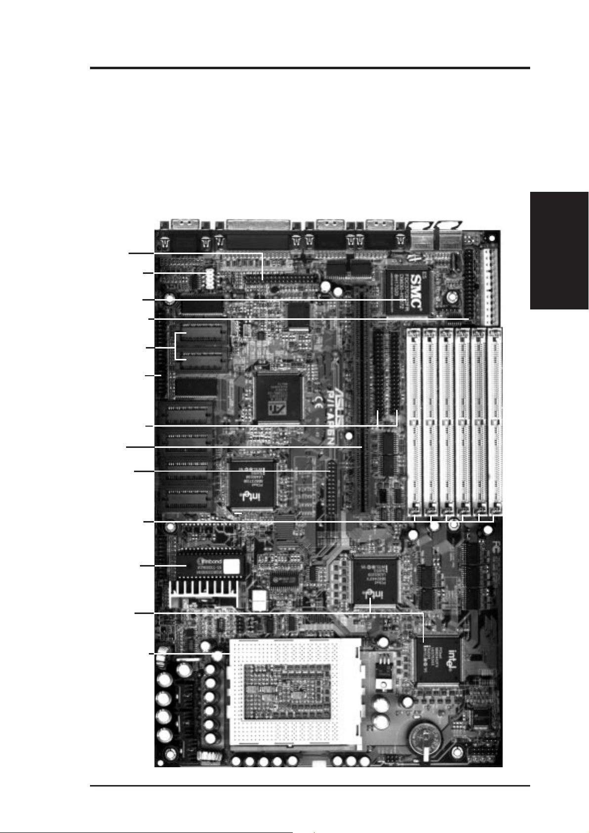
Parts of the ASUS Motherboard
PS/2
Mouse
PS/2
Keyboard
Audio Port
USB Connector
(Reserved)
Multi-I/O & RTC
Floppy Connector
VGA Memory
Upgrade Sockets
Monitor
Parallel COM 2
COM 1
II. FEATURES
(Parts of Board)
AMC Connector
IDE Connectors
Riser Slot
Audio Wave
Table Upgrade
(6) 72-pin SIMM
DRAM Sockets
Programmable
Flash ROM
Intel's 440FX
PCIset
CPU ZIF Socket 8
ASUS P/I-AP6N User’s Manual 9
Page 10

III. INSTALLATION
Map of the ASUS Motherboard
III. INSTALLATION
(Map of Board)
VGA Output
512KB DRAM
512KB DRAM
AMC Connector
512KB DRAM
Upgrade Socket
512KB DRAM
Upgrade Socket
512KB DRAM
512KB DRAM
512KB DRAM
512KB DRAM
Upgrade Socket
512KB DRAM
512KB DRAM
Upgrade Socket
Parallel Connector
USB
Audio Connector
Sony CD In
Panasonic CD In
Mitsumi CD In
ATI 3D Rage II
Video Chipset
Intel PIIX3
PCIset
Serial COM2
Audio (En/Dis)
Creative
Labs
ViBRA
Audio
Serial COM1
Raiser Card Connector
Secondary IDE
R
Wave Table Upgrade
PS/2
Mouse
PS/2
Keyboard
Super
Multi-I/O
JP2
JP3
Primary IDE
SIMM Socket 1 (Bank 0)
SIMM Socket 2 (Bank 0)
SIMM Socket 3 (Bank 1)
Floppy Drives
Board Power Input
P8
P9
SIMM Socket 4 (Bank 1)
SIMM Socket 5 (Bank 2)
SIMM Socket 6 (Bank 2)
IDE LED
Panel Connectors
Volume Control
Infrared
Gnd
Up
Gnd
Down
Gnd
BBLKW
Flash ROM
for BIOS
VID0
VID1
VID2
VID3
CPU Voltage
BF0
BF1
BF2
BF3
Freq. Ratio
Intel 440FX
PCIset
BUS FREQ
FS0
FS1
CPU ZIF Socket 8
FANPWR1
Intel 440FX
PCIset
CR2032
3 Volts
Lithium
Button Cell
RTCLR
FANPWR2
CHASSIS
FANPWR3
10 ASUS P/I-AP6N User’s Manual
Page 11

III. INSTALLATION
Jumpers
1) BBLKW p. 13 Flash ROM Boot Block Program (Enable/Disable)
2) RTCLR p. 14 Real Time Clock RAM (Operation/Clear CMOS Data)
3) AUDIO_JP p. 15 Audio Selection (Enabled/Disabled)
4) FS0, FS1 p. 16 CPU External Clock (BUS) Frequency Selection
5) BF0, BF1, BF2, BF3 p. 16 CPU:BUS Frequency Ratio
6) VID0 - VID3 p. 17 Voltage Regulator Output Selection
Expansion Slots
1) SIMM Sockets p. 18 DRAM Memory Expansion Sockets
2) CPU ZIF Socket 8 p. 21 Central Processing Unit (CPU) Socket
3) Riser Slot p. 22 Slot for a Riser Expansion Slot Card
Connectors
1) PS2KB p. 24 PS/2 Keyboard Connector (6-pin Female)
2) PS2MOUSE p. 24 PS/2 Mouse Connector (6-pin Female)
3) COM1, COM2 p. 24 Serial Port COM1 & COM2 (9-pin Male)
4) PRINTER p. 25 Parallel (Printer) Port Connector (25-pin Female)
5) Video Monitor Output p. 25 Video Connector for Video Monitor (15-pin Female)
6) FLOPPY p. 25 Floppy Drive Connector (34-pin Block)
7) IDE1, IDE2 p. 26 Primary / Secondary IDE Connector (40-pin Blocks)
8) IDELED p. 26 IDE LED Activity Light
9) TB LED (PANEL) p. 27 Turbo LED/Power LED (2-pins)
10) SMI (PANEL) p. 27 SMI Switch Lead (2-pins)
11) RESET (PANEL) p. 27 Reset Switch Lead (2-pins)
12) KEYLOCK (PANEL) p. 27 Keyboard Lock Switch Lead (5-pins)
13) SPEAKER (PANEL) p. 27 Speaker Connector (4-pins)
14) IR p. 28 Infrared Port Module Connector
15) VOL_CON p. 28 Digital Volume Control (Up/Down)
16) FANPWR1, 2, 3 p. 29 1 CPU, 2 Power Supply, 3 Chassis Fan Power Leads (6-pin Block)
17) CHASSIS p. 29 Chassis Open Alarm Lead (3-pin Block)
18) Power Input p. 30 Motherboard Power Connector (12-pin Block)
(Map of Board)
III. INSTALLATION
ASUS P/I-AP6N User’s Manual 11
Page 12
III. INSTALLATION
Installation Steps
Before using your computer, you must follow the six steps as follows:
1. Set Jumpers on the Motherboard
2. Install DRAM Modules
3. Install the CPU
4. Install Expansion Cards
5. Connect Cables, Wires, and Power Supply
6. Setup the BIOS Software
1. Jumpers
Several hardware settings are made through the use of jumper caps to connect jumper
pins (JP) on the motherboard. See "Map of the Motherboard" on page 4 for loca-
III. INSTALLATION
(Jumpers)
tions of jumpers. The jumper settings will be described numerically such as [----],
[1-2], [2-3] for no connection, connect pins 1&2, and connect pins 2&3 respectively. Pin 1 for our motherboards is always on top
holding the motherboard with the keyboard connector away from yourself. A "1" is
written besides pin 1 on jumpers with three pins. The jumpers will also be shown
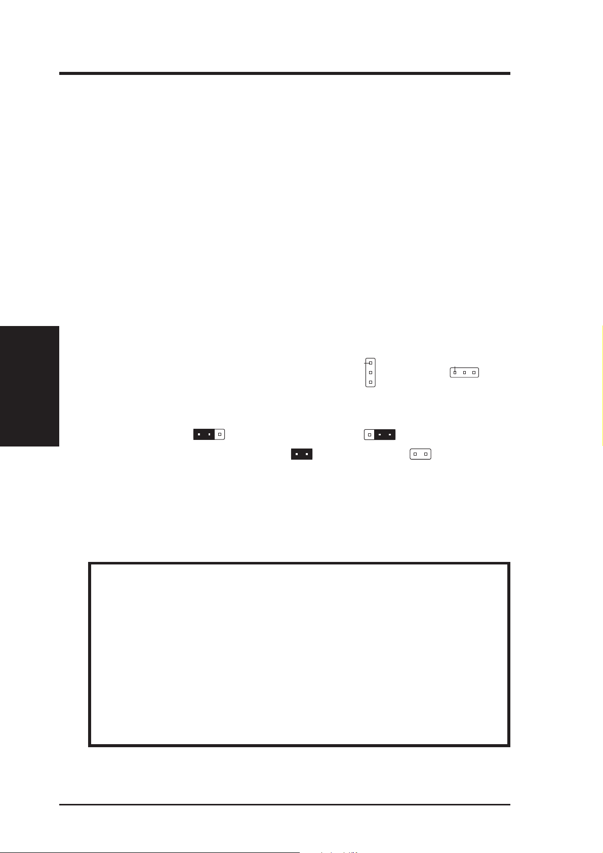
graphically such as
Jumpers with two pins will be shown as
For manufacturing simplicity, the jumpers may be sharing pins from other groups.
Use the diagrams in this manual instead of following the pin layout on the board.
Settings with two jumper numbers require that both jumpers be moved together . To
connect the pins, simply place a plastic jumper cap over the two pins as diagramed.
WARNING: Computer motheboards and components contain very delicate
Integrated Circuit (IC) chips. To protect the motherboard and other components against damage from static electricity, you should follow some precautions whenever you work on your computer.
1. Unplug your computer when working on the inside.
2. Hold components by the edges and try not to touch the IC chips, leads, or
circuitry.
3. Use a grounded wrist strap before handling computer components.
4. Place components on a grounded antistatic pad or on the bag that came with
the component whenever the components are separated from the system.
to connect pins 1&2 and to connect pins 2&3.
for short (On) and for open (Off).
Pin 1
or on the left
Pin 1
when
12 ASUS P/I-AP6N User’s Manual
Page 13

III. INSTALLATION
Jumper Settings
1. Flash ROM Boot Block Programming (BBLKW)
This sets the operation mode of the boot block area of the BIOS Flash ROM to
allow programming in the Enabled position.
Programming BBLKW
Disabled [1-2] (Default)
Enabled [2-3]
BBLKW
1
2
3
R
Disabled / Protected
(Default)
Boot Block Programming (Disable / Enable)
BBLKW
1
2
3
Enabled
(Jumpers)
III. INSTALLATION
ASUS P/I-AP6N User’s Manual 13
Page 14

III. INSTALLATION
(Jumpers)
III. INSTALLATION
2. Real Time Clock (RTC) RAM (RTCLR)
The CMOS RAM is powered by the onboard button cell battery. To clear the
RTC data: (1) Turn off your computer, (2) Move this jumper to “Clear Data,”
(3) Power on your computer, (4) Turn off your computer, (5) Move the jumper
back to “Operation,” (6) T urn on your computer, (7) Hold down <Delete> during
bootup and enter BIOS setup to re-enter user preferences.
Battery Test Jumper (RTCLR)
You can test the battery’s current by removing this jumper and attaching a current meter to pins 2&3. WARNING: You must unplug the power cord to
your power supply to ensure that there is no power to your motherboard.
The CMOS RAM containing BIOS setup information may be cleared by
this action. You should enter BIOS to “Load Setup Defaults” and r e-enter
any user information after removing and reapplying this jumper.
RTC RAM RTCLR
Operation [2-3] (Default)
Clear Data [1-2] (momentarily)
R
RTCLR
1
2
3
(Default)
Real Time Clock RAM (Operation / Clear CMOS Data)
RTCLR
1
2
3
Clear CMOS DataOperation
14 ASUS P/I-AP6N User’s Manual
Page 15

III. INSTALLATION
3. Onboard Audio Selection (AUDIO_JP)
This jumper allows you to Disable the onboard audio chipset in order to use
your own audio card. Otherwise, leave on default of Enabled.
Onboard Audio AUDIO_JP
Enabled [1-2] (Default)
Disabled [2-3]
AUDIO_JP
1
2
3
R
Enabled
(Default)
Onboard Audio Selection (Enable / Disabled)
AUDIO_JP
1
2
3
Disabled
(Jumpers)
III. INSTALLATION
ASUS P/I-AP6N User’s Manual 15
Page 16

III. INSTALLATION
4. CPU External (BUS) Frequency Selection (FS0, FS1)
These jumpers tell the clock generator what frequency to send to the CPU. These
allow the selection of the CPU’ s External frequency (or BUS Clock). The BUS
Clock times the BUS Ratio equals the CPU's Internal frequency (the advertised
CPU speed).
5. CPU to BUS Frequency Ratio (BF0, BF1, BF2, BF3)
These jumpers set the frequency ratio between the Internal frequency of the
CPU and the External frequency (called the BUS Clock) within the CPU. These
must be set together with the above jumpers CPU External (BUS) Frequency
Selection.
FS1
FS0
FS1
FS0
FS1
FS0
FS1
FS0
III. INSTALLATION
(Jumpers)
R
CPU External Clock (BUS) Frequency Selection
BF0
BF1
BF2
BF3
CPU : BUS Frequency Ratio (2.0x, 2.5x, 3.0x, 3.5x, 4.0x)
60MHz 66MHzReserved Reserved
BF0
BF1
BF2
BF3
BF0
BF1
BF2
BF3
BF0
BF1
BF2
BF3
3.5 x2.0 x 2.5 x 3.0 x 4.0 x
BF0
BF1
BF2
BF3
Set the jumpers by the Internal speed of the Intel CPU as follows:
(BUS Freq.) (CPU to BUS Freq. Ratio)
Freq. Ratio BUS Freq. FS1 FS0 BF0 BF1 BF2 BF3
200MHz 3.0x 66MHz [1-2] [2-3] [ON] [OFF] [ON] [ON]
180MHz 3.0x 60MHz [2-3] [1-2] [ON] [OFF] [ON] [ON]
166MHz 2.5x 66MHz [1-2] [2-3] [OFF] [ON] [ON] [ON]
150MHz 2.5x 60MHz [2-3] [1-2] [OFF] [ON] [ON] [ON]
16 ASUS P/I-AP6N User’s Manual
Page 17
III. INSTALLATION
6. Voltage Regulator Output Selection (VID0 -VID3)
Pentium Pro Processors may require different voltages. Current processors
(marked “Pentium Pro”) support VID and will automatically adjust the voltage
regulator so that no jumper settings are needed (leave these jumpers open in this
case). Older processors without VID support require manual voltage ID setting.
Use [S] for Short and [O] for Open.
Voltage 3.5 3.4 3.3 3.2 3.1 3.0 2.9 2.8 2.7 2.6 2.5 2.4 2.3 2.2 2.1 Auto
VID 0 [S] [O] [S] [O] [S] [O] [S] [O] [S] [O] [S] [O] [S] [O] [S] [O]
VID 1 [S] [S] [O] [O] [S] [S] [O] [O] [S] [S] [O] [O] [S] [S] [O] [O]
VID 2 [S] [S] [S] [S] [O] [O] [O] [O] [S] [S] [S] [S] [O] [O] [O] [O]
VID 3 [S] [S] [S] [S] [S] [S] [S] [S] [O] [O] [O] [O] [O] [O] [O] [O]
AUTO
R
VID0
VID1
VID2
VID3
(Default)
(Jumpers)
Voltage Regulator Output Selection
III. INSTALLATION
ASUS P/I-AP6N User’s Manual 17
Page 18

2. System Memory
This motherboard supports six 72-pin SIMMs (Single Inline Memory Modules) of
4MB, 8MB, 16MB, 32MB, or 64MB to form a memory size between 8MB to 384MB.
The DRAM can be either 60ns or 70ns Fast Page Mode (FPM) (Asymmetric or
Symmetric), Extended Data Out (EDO), or Burst Extended Data Out (BEDO).
SIMMs must be installed in pairs so that each bank contains two of the same size
memory modules. Maximum memory size of each memory bank must be 128MB
or less. To support Error Checking and Correcting (ECC), you must use true (opposed to phantom parity generated by TTL chips) 36-bit parity-type SIMM (e.g. 8
chips + 4 parity chips ) in pairs for all modules. Mixing 32-bit non-parity SIMM (e.
g. 8 chips) and 36-bit SIMM (e.g. 12 chips) will work minus the ECC feature.
IMPORTANT: Memory speed setup is r equir ed in BIOS Chipset Setup "Auto
III. INSTALLATION
(System Memory)
Configuration."
Install memory in any or all of the banks in any combination as follows:
III. INSTALLATION
Bank Memory Module Total Memory
Bank 0 4MB, 8MB, 16MB, 32MB, 64MB x2
SIMM Sockets 1&2 72-pin FPM, EDO, BEDO SIMM
Bank 1 4MB, 8MB, 16MB, 32MB, 64MB x2
SIMM Sockets 3&4 72-pin FPM, EDO, BEDO SIMM
Bank 2 4MB, 8MB, 16MB, 32MB, 64MB x2
SIMM Sockets 5&6 72-pin FPM, EDO, BEDO SIMM
Total System Memory (Max 384MB) =
IMPORTANT: The same size and type (FPM, EDO, BEDO) of memory must
be installed in pairs so that memory modules are not mixed in each bank. Do
not use memory modules with more than 24 chips per module. Modules with
more than 24 chips exceed the design specifications of the memory subsystem
and will be unstable.
18 ASUS P/I-AP6N User’s Manual
Page 19

III. INSTALLATION
DRAM in SIMM Sock
SIMM Memory Installation Procedures:
1. The SIMM memory modules will only fit in one orientation as shown because
of a "Plastic Safety Tab" on one end of the SIMM slots which requires the
"Notched End" of the SIMM memory modules.
1234
R
Bank 0 Bank 1
65
Bank 2
Notched End
72 Pin SIMM DRAM Sockets
2. Press the memory module firmly into place starting from a 45 degree angle
making sure that all the contacts are aligned with the socket.
(System Memory)
III. INSTALLATION
3. W ith your finger tips, rock the memory module into a vertical position so that it
clicks into place.
72 Pin
Metal Clip
Plastic Safety Tab (This Side Only)
et
Mounting Hole
4. The plastic guides should go through the two "Mounting Holes" on the sides and
the "Metal Clips" should snap on the other side.
5. To release the memory module, squeeze both "Metal Clips" outwards and rock
the module out of the "Metal Clips".
ASUS P/I-AP6N User’s Manual 19
Page 20

III. INSTALLATION
VGA Memory Upgrade
The ASUS P/I-AP6N motherboard comes with 2MB DRAM for the onboard VGA.
Four sockets are available to upgrade the VGA memory to 4MB by adding four
512KB DRAM chips. 3MB is not supported on this product. Specifications may
change without notice.
Onboard VGA DRAM Specification:
40 pins SOJ, 256Kx16, DUAL CAS EDO DRAM 40ns
Suggested VGA DRAM for P/I-AP6N:
1. TM T224162A-40JE
2. EtronTech Em614163A-40
III. INSTALLATION
(System Memory)
This is an example of an installed DRAM. The indentation is made white for visibility, it is normally black.
1. Match the small indentation on the chip’s sloped edge with the socket’ s cut corner .
2. Place the chip flat and evenly into the socket and press firmly but carefully so that
the chip enters evenly. When installed, the chip should be flush with the socket.
WARNING: Installing the memory chip incorrectly may damage the memory
and the product itself.
IMPORTANT: Make sure that all VGA memory are of the same type and speed to
ensure reliable operation.
Small indentation on the chip's sloped edge
Socket's cut corner
20 ASUS P/I-AP6N User’s Manual
Page 21

III. INSTALLATION
3. Central Processing Unit (CPU)
The motherboard provides a 387-pin ZIF Socket 8. The CPU that came with the
motherboard should have a fan attached to it to prevent overheating. If this is not the
case then purchase a fan before you turn on your system. Apply thermal jelly to the
CPU top and then install the fan onto the CPU.
WARNING: Without a fan circulating air on the CPU and heat sinks, the
CPU and/or heat sinks can overheat and cause damage to both the CPU and the
motherboard. (See "CPU Cooling Fan Connector” at the end of this section.)
To install a CPU, first turn off your system and remove its cover. Locate the ZIF
socket and open it by first pulling the lever sideways away from the socket then
upwards to a 90-degree right angle. Insert the CPU with the correct orientation as
shown. Use the notched corner of the CPU with the white dot as your guide. The
white dot should point towards the end the of the lever . Notice that there is a blank
area where one hole is missing from that corner of the square array of pin holes and
a "1" printed on the motherboard next to that corner . Because the CPU has a corner
pin for three of the four corners, the CPU will only fit in the one orientation as
shown. The picture is for reference only; you should have a CPU fan that will cover
the face of the CPU. W ith the added weight of the CPU fan, no force is required to
insert the CPU. Once completely inserted, hold down on the fan and close the
socket's lever.
(CPU)
III. INSTALLATION
IMPORTANT: You must set jumpers for "CPU to BUS Frequency Ratio" and
jumpers for "BUS Frequency Selection" depending on the CPU that you install.
R
ZIF Socket 8 with Pentium Pro Processor
ASUS P/I-AP6N User’s Manual 21
Page 22

4. Expansion Cards
WARNING: Make sure that you unplug your power supply when adding or
removing expansion cards or other system components. Failure to do so may
cause severe damage to both your motherboard and expansion cards.
IMPORTANT: This motherboard requires a Riser card in order to add expansion
cards. Insert the Riser card provided by your retailer into the Riser slot with the
notch over the safety tab. The Riser card cannot be inserted in the wrong orientation
because of the safety tab. The following is an example only. Your riser card may
look different. Check your system manual for specific settings that may be needed.
III. INSTALLATION
(Expansion Cards)
III. INSTALLATION
Expansion Card Installation Procedure:
1. Read the documentation for your expansion card.
2. Set any necessary jumpers on your expansion card.
3. Remove your computer system's cover.
4. Remove the bracket on the slot you intend to use. Keep the bracket for
possible future use.
5. Carefully align the card’s connectors and press firmly.
6. Secure the card on the slot with the screw you removed in step 4.
7. Replace the computer system's cover.
8. Setup the BIOS if necessary (such as "IRQ xx Used By ISA: Yes" in PNP AND
PCI SETUP)
9. Install the necessary software drivers for your expansion card.
Assigning IRQs for Expansion Cards
Some expansion cards need to use an IRQ to operate. Generally an IRQ must be
exclusively assigned to one use. In an standard design there are 16 IRQs available
but most of them are already in use by parts of the system which leaves 6 free for
expansion cards.
22 ASUS P/I-AP6N User’s Manual
Page 23

III. INSTALLATION
Both ISA and PCI expansion cards may need to use IRQs. System IRQs are available to cards installed in the ISA expansion bus first, and any remaining IRQs are
then used by PCI cards. Currently, there are two types of ISA cards. The original
ISA expansion card design, now referred to as “Legacy” ISA cards, requires that
you configure the card’ s jumpers manually and then install it in any available slot on
the ISA bus. You may use Microsoft's Diagnostic (MSD.EXE) utility included in
the Windows directory to see a map of your used and free IRQs. For Windows 95
users, the "Control Panel" icon in "My Computer," contains a "System" icon which
gives you a "Device Manager" tab. Double clicking on a specific device give you
"Resources" tab which shows the Interrupt number and address. Make sure that no
two devices use the same IRQs or your computer will experience problems when
those two devices are in use at the same time.
T o simplify this process this motherboard has complied with the Plug and Play (PNP)
specification which was developed to allow automatic system configuration whenever a PNP-compliant card is added to the system. For PNP cards, IRQs are assigned automatically from those available.
If the system has both Legacy and PNP ISA cards installed, IRQs are
assigned to PNP cards from those not used by Legacy cards. The PCI and PNP
configuration of the BIOS setup utility can be used to indicate which IRQs are being
used by Legacy cards. For older Legacy cards that does not work with the BIOS,
you can contact your vendor for an ISA Configuration Utility.
An IRQ number is automatically assigned to PCI expansion cards after those used
by Legacy and PNP ISA cards. In the PCI bus design, the BIOS automatically
assigns an IRQ to a PCI slot that has a card in it that requires an IRQ. To install a
PCI card, you need to set something called the INT (interrupt) assignment. Since all
the PCI slots on this motherboard use an INTA #, be sure that the jumpers on your
PCI cards are set to INT A.
Assigning DMA Channels for ISA Cards
Some ISA cards, both Legacy and PNP may also need to use a DMA (Direct Memory
Access) channel. DMA assignments for this motherboard are handled the same way
as the IRQ assignment process described above. You can select a DMA channel in
the PCI and PNP configuration section of the BIOS Setup utility.
(DMA Channels)
III. INSTALLATION
IMPORTANT: Choose "Yes" for those IRQ's and DMA's you wish to r eserve
for Legacy (Non-PnP) ISA expansion cards in “IRQ xx Used By ISA” and “DMA
x Used By ISA” of the PNP and PCI Setup in the BIOS SOFTWARE section,
otherwise conflicts may occur.
ASUS P/I-AP6N User’s Manual 23
Page 24
III. INSTALLATION
5. External Connectors
WARNING: Some pins are used for connectors or power sources. These are
clearly separated from jumpers in "Map of the Motherboard". Placing jumper
caps over these will cause damage to your motherboard.
IMPORTANT: Ribbon cables should always be connected with the red stripe
on the Pin 1 side of the connector. The four corners of the connectors are labeled on the motherboard. Pin 1 is the side closest to the power connector on
hard drives and floppy drives. IDE ribbon cable must be less than 18in. (46cm),
with the second drive connector no more than 6in. (15cm) from the first connector.
III. INSTALLATION
(Connectors)
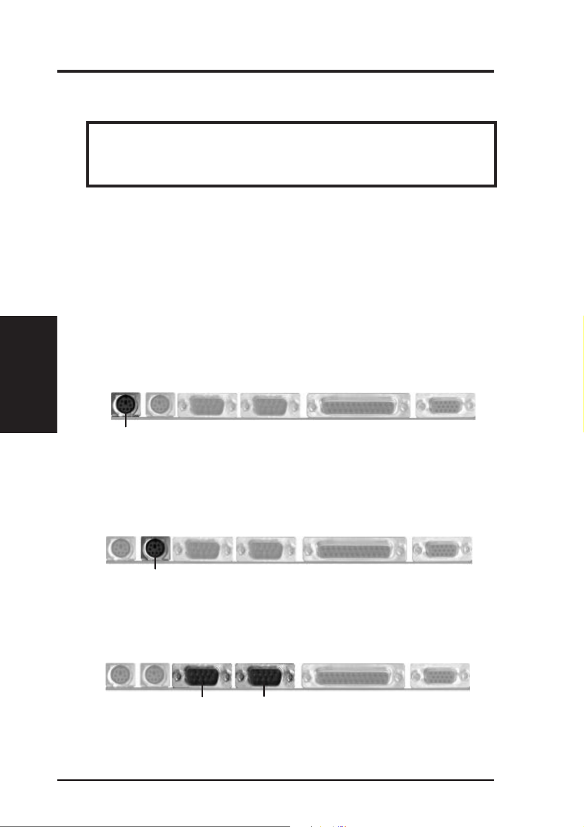
1. PS/2 Keyboard Connector (6-pin Female)
This connection is for a standard keyboard using a PS/2 plug (mini DIN). This
connector will not allow standard AT size (large DIN) keyboard plugs. You
may use a DIN to mini DIN adapter on standard AT keyboards.
PS/2 Keyboard (6-pin Female)
2. PS/2 Mouse Connector (6-pin Female)
The system will direct IRQ12 to the PS/2 mouse if one is detected. If not detected, expansion cards can use IRQ12. See "PS/2 Mouse Control" in BIOS
Features Setup of the BIOS SOFTWARE.
PS/2 Mouse (6-pin Female)
3. Serial Port COM1 and COM2 Connectors (Two 9-pin Male)
The two serial ports can be used for pointing devices or other serial devices. See
"Onboard Serial Port" in Chipset Features Setup of the BIOS SOFTWARE.
COM 1 COM 2
Serial Ports (9-pin Male)
24 ASUS P/I-AP6N User’s Manual
Page 25
III. INSTALLATION
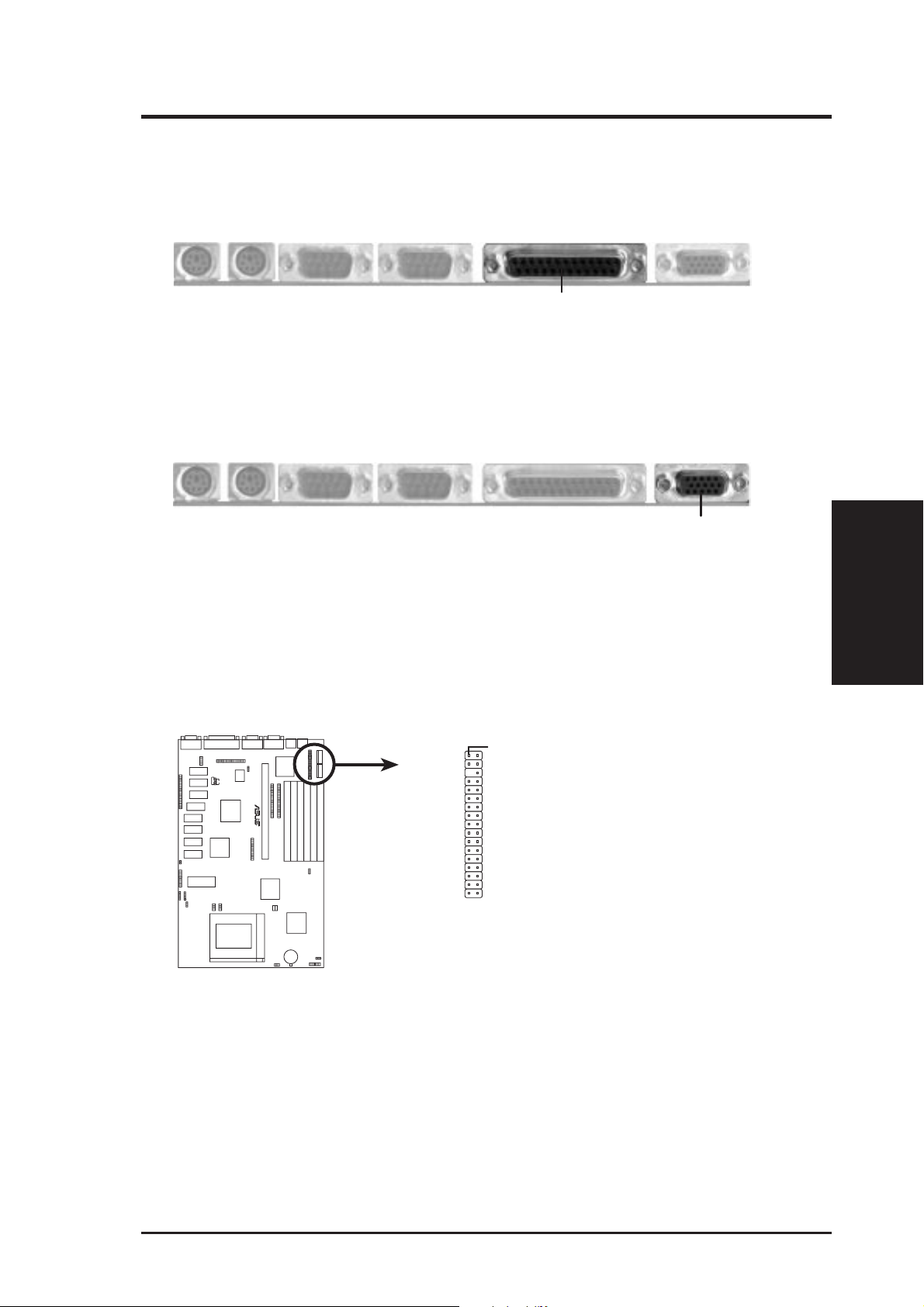
4. Parallel Printer Connector (25-pin Female)
You can enable the parallel port and choose the IRQ through "Onboard Parallel
Port" in Chipset Features Setup of the BIOS SOFTW ARE. NOTE: Serial printers
must be connected to the serial port.
Parallel (Printer) Port (25-pin Female)
5. Video Monitor Output (15-pin Female)
There is a built-in video chip on this motherboard so that a separate video card is
not necessary. Connect your monitor cable to the onboard monitor output
connector.
Video Monitor Output (15-pin Female)
6. Floppy Drive Connector (34-pin block )
This connector supports the provided floppy drive ribbon cable. After connecting the single end to the board, connect the two plugs on the other end to the
floppy drives. (Pin 5 is removed to prevent inserting in the wrong orienta-
tion when using ribbon cables with pin 5 plugged).
Pin 1
Connect the Red stripe to Pin 1
R
Floppy Drive Connector
(Connectors)
III. INSTALLATION
ASUS P/I-AP6N User’s Manual 25
Page 26

III. INSTALLATION
(Connectors)
III. INSTALLATION
7. Primary / Secondary IDE Connectors (Two 40-pin Block)
These connectors support the provided IDE hard disk ribbon cable.
After connecting the single end to the board, connect the two plugs at the other
end to your hard disk(s). If you install two hard disks, you must configure the
second drive to Slave mode by setting its jumper accordingly . Please refer to the
documentation of your hard disk for the jumper settings. BIOS now supports
SCSI device or IDE CD-ROM bootup (see "HDD Sequence SCSI/IDE First" &
"Boot Sequence" in the BIOS Features Setup of the BIOS SOFTWARE) (Pin
20 is removed to prevent inserting in the wrong orientation when using
ribbon cables with pin 20 plugged).
TIP: You may configure two hard disks to be both Masters using one ribbon
cable on the primary IDE connector and another ribbon cable on the secondary
IDE connector. You may install one operating system on an IDE drive and
another on a SCSI drive and select the boot disk through BIOS Features Setup.
Pin 1
R
Primary IDE Connector
Connect the Red stripe to Pin 1
Secondary IDE Connector
8. IDE Activity LED (IDE LED)
This connector supplies power to the cabinet’s IDE activity LED. Read and
write activity by devices connected to the Primary or Secondary IDE connectors
will cause the LED to light up.
R
TIP: If the case-mounted LED does not light,
try reversing the 2-Pin plug.
+
IDE (Hard Drive) Activity LED
26 ASUS P/I-AP6N User’s Manual
Page 27

III. INSTALLATION
9. System Power LED (TB LED)
The motherboard's turbo function is always on. The turbo LED connection is
labeled here but the LED will remain constantly lit while the system power is
on. You may wish to connect the Power LED from the system case to this lead.
See the figure below.
10. SMI Suspend Switch Lead (SMI)
This allows the user to manually place the system into a suspend mode or "Green"
mode where system activity will be instantly decreased to save electricity and
expand the life of certain components when the system is not in use. This 2-pin
connector (see the figure below) connects to the case-mounted suspend switch.
If you do not have a switch for the connector, you may use the "Turbo Switch"
since it does not have a function. SMI is activated when it detects a short to
open moment and therefore leaving it shorted will not cause any problems. May
require one or two pushes depending on the position of the switch. W ake-up can
be controlled by settings in the BIOS but the keyboard will always allow wakeup (the SMI lead cannot wake-up the system). If you want to use this connector,
"Suspend Switch" in the POWER MANAGEMENT SETUP of the BIOS software should be on the default setting of Enable. See the figure below.
11. Reset Switch Lead (RESET)
This 2-pin connector connects to the case-mounted reset switch for rebooting
your computer without having to turn off your power switch This is a preferred
method of rebooting in order to prolong the life of the system's power supply.
See the figure below.
12. Keyboard Lock Switch Lead & System Power LED (KEYLOCK)
This 5-pin connector connects to the case-mounted keyboard lock switch for
locking the keyboard and also to connect the system power LED. The system
power LED lights when the system is powered on. See the figure below.
13. Speaker Connector (SPEAKER)
This 4-pin connector connects to the case-mounted speaker.
System
Power LED
R
SMI Lead
Reset SW
+5V
GND
GND
GND
GND
+5V
System
NC
Power LED
GND
LOCK
Keyboard Lock
GND
+5V
Speaker
GND
GND
Connector
SPKR
(Connectors)
III. INSTALLATION
System Case Connections
ASUS P/I-AP6N User’s Manual 27
Page 28

III. INSTALLATION
14. IrDA-Compliant Infrared Module Connector (IR)
This connector supports the optional wireless transmitting and receiving infrared module. This module mounts to a small opening on system cases that support this feature. You must also configure the setting through "UART2 Use
Infrared" in Chipset Features Setup to select whether UART2 is directed for
use with COM2 or IrDA. Use the five pins as shown on the Back View and
connect a ribbon cable from the module to the motherboard according to the pin
definitions.
III. INSTALLATION
(Connectors)
NC
GND
R
Infrared Module Connector
+5V
IRRX
IRTX
Front View
Back View
IRTX
GND
+5V
NC
IRRX
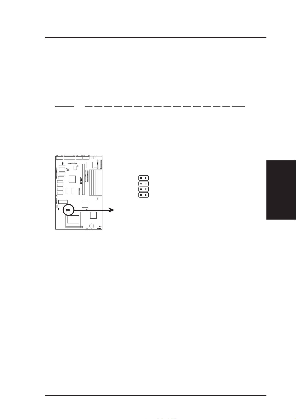
15. Onboard Digital Audio Control (VOL_CON)
This jumper allows you to adjust the audio volume digitally using case mounted
momentary buttons.
Audio Control VOL_CON
Volume Up [1-2] (momentary)
Volume Down [4-5] (momentary)
VOL_CON
Ground
1
Volume Up
2
Ground
3
Volume Down
R
4
Ground
5
Onboard Digital Audio Control
28 ASUS P/I-AP6N User’s Manual
Page 29

III. INSTALLATION
16. CPU Cooling Fan, Power Supply Fan, & Chassis Fan Power Connectors (F ANPWR)
These connectors support cooling fans of 500mAMP (6WATT) or less. Orientate the fans so that the heat sink fins allow airflow to go across the onboard heat
sink(s) instead of the expansion slots. Depending on the fan manufacturer, the
wiring and plug may be different. The red wire should be positive, while the
black should be ground. Connect the fan's plug to the board taking into consideration the polarity of the this connector . NOTE: The “Rotation” signal is to
be used only by a specially designed fan with rotation signal.
WARNING: The CPU and/or motherboard will overheat if there is no air-
flow across the CPU and onboard heatsinks. Damage may occur to the
motherboard and/or the CPU fan if these pins are incorrectly used. These
are not jumpers, do not place jumper caps over these pins.
CPU Fan Power
Power Supply Fan
Chassis Fan Power
+12V
R
GND
+12V
GND
12Volt CPU, Power Supply, & Chassis Fan Power
Air Flow
Orientate the fins so that air flow
runs across motherboard's heatsinks.
Air Flow
17. Chassis Open Alarm Lead (CHASSIS)
This lead is for an open chassis monitor. A high level signal to the CHASSIS
lead will indicate to the system that the chassis has been opened.
R
+5V GND
(Connectors)
III. INSTALLATION
CHASSIS
Chassis open alarm lead
ASUS P/I-AP6N User’s Manual 29
Page 30

III. INSTALLATION
18. Power Input Connector (12-pin block)
This connector connects to a standard 5 Volt power supply . To connect the leads
from the power supply, ensure first that the power supply is not plugged. Most
power supplies provide two plugs (P8 and P9), each containing six wires, two of
which are black. Orient the connectors so that the black wires are together.
III. INSTALLATION
(Connectors)
+5V
-12V
R
-5V
AT Power Connector
on Motherboard
PG
+12V
GND
+5V
P8
P9
Power Plugs from
Power Supply
ORG
RED
YLW
BLU
BLK
BLK
BLK
BLK
WHT
RED
RED
RED
Using a slight angle, align the plastic guide pins on the lead to their receptacles
on the connector . Once aligned, press the lead onto the connector until the lead
locks into place.
AT Power Connector with ATX Power Supply (3-pin JP2)
For ATX Power Switch, Soft Power Switch, and remote power on functions, an
ATX power supply and an ATX to AT power connector adapter are required.
The ATX to AT power connector adapter will allow an ATX power supply to be
used on this AT motherboard with additional ATX signals connected to this lead.
The ATX power switch button will be connected to JP3.
+5V Standby (Vlt)
Ground (Blk)
Power On (Grn)
R
JP2JP3
For ATX soft power features
on this AT motherboard, you
need an ATX power supply,
optional A TX to AT power
connector adapter, and a
momentary switch button.
ATX Power Switch Lead
To ATX Power Supply
To AT Power Connector
Optional ATX to A T Power
Connector Adapter
ATX Power Switch (2-pin JP3)
The system power can be controlled by a momentary switch connected to JP3.
Pushing the button once (push slowly) will switch the system between ON and
OFF. The system power LED shows the status of the system's power.
30 ASUS P/I-AP6N User’s Manual
To PWRATX
Page 31

III. INSTALLATION
Power Connection Procedures
1. After all jumpers and connections are made, close the system case cover.
2. Make sure that all switches are in the off position as marked by
3. Connect the power supply cord into the power supply located on the back of
your system case as instructed by your system user's manual.
4. Connect the power cord into a power outlet that is equipped by a surge protector .
5. You may then turn on your devices in the following order:
a. Your monitor
b. External SCSI devices (starting with the last device on the chain)
c. Your system power. For ATX power supplies, you need to switch
on the power supply as well as press the ATX power switch on the
front of the case.
6. The power LED on the front panel of the system case will light. For ATX power
supplies, the system LED will light when the ATX power switch is pressed. The
monitor LED may light up after the system's if it complies with "Green" standards or if it has a power standby feature. The system will then run power-on
tests. While the tests are running, additional messages will appear on the screen.
If you do not see anything within 30 seconds from the time you turn on the
power, the system may have failed a power-on test. Recheck your jumper settings and connections or call your retailer for assistance.
.
III. INSTALLATION
(Power Connections)
7. During power-on, hold down the <Delete> key to enter BIOS setup. Follow the
next section "BIOS SOFTWARE" for instructions.
* Powering Off your computer: You must first exit or shut down your operating
system before switching off the power switch. For ATX power supplies, you
can press the ATX power switch after exiting or shutting down your operating
system. For W indows 95 users, you can select shut down the computer from the
"Start" button and the system will give three quick beeps after about 30 seconds
and power off after windows shut down. NOTE: The message: "It's now safe to
turn off your computer" will not be shown in Windows 95 when using shut
down with ATX power supplies.
31ASUS P/I-AP6N User's Manual
Page 32

IV. BIOS SOFTWARE
Support Software
FILELIST.TXT - View this file to see the files included in the support software.
PFLASH.EXE - This is the Flash Memory Writer utility that updates the BIOS by
uploading a new BIOS file to the programmable flash ROM chip on the motherboard. To determine the BIOS version, check the last four numbers of the code
displayed on the upper left-hand corner of your screen during bootup. Larger numbers represent a newer BIOS file.
NOTE: A binary BIOS file is no longer included with the support software.
Save the motherboard's BIOS file to a floppy diskette as soon as your system is
operational. See "Flash Memory Writer Utility" below.
Flash Memory Writer Utility
ASUSTeK PNP BIOS
Copyright (C) 1995, ASUSTeK COMPUTER Inc.
FLASH MEMORY WRITER V1.5
(Flash Memory Writer)
IV. BIOS
Flash Type -- SST 29EE010
Current BIOS Revision: #401A0-xxxx
Choose one of the following:
1. Save Current BIOS To File
2. Update BIOS Main Block From File
3. Advanced Features
Enter Choice: [1]
Press ESC To Exit
xxxx denotes the current BIOS version stored in the Flash EPROM
IMPORTANT: Flash Type may also be "INTEL 28F001BXT." If "unknown"
is shown after "Flash type --," then this ROM chip is not programmable or not
supported with the PnP BIOS and therefore cannot be programmed by the
Flash Memory Writer.
Main Menu
1. Save Current BIOS to File (Perform as soon as system is operational)
This option allows you to copy the contents of the Flash memory chip onto a diskette. This gives you a backup copy of the original motherboard BIOS in case you
need to re-install it.
Create a bootable system floppy diskette by typing [FORMAT A:/S] from the
DOS environment without creating "AUTOEXEC.BAT" and "CONFIG.SYS"
files, then copy PFLASH.EXE to the newly formatted diskette and then save
your BIOS to the same diskette.
32 ASUS P/I-AP6N User's Manual
Page 33

IV. BIOS SOFTWARE
2. Update BIOS Main Block from File
This option updates the BIOS from a file on the disk. This can either be a new file
or a backup file created by the “Save Current BIOS to File” option. This will not
update the Boot Block if the Boot Block is different. You will be prompted with the
following if advanced features if necessary.
Boot Block of New BIOS is different from old one !!!
Please Use 'Advanced Feature' to flash whole bios !!!
3. Advanced Features
Selecting this option brings up the Advanced Features screen for clearing the PnP
configuration record and updating the motherboard BIOS.
Advanced Features Menu
Advanced Features
Flash Type -- SST 29EE010
Current BIOS Revision: #401A0-xxxx
Choose one of the following:
1. Clear PNP ESCD Parameter Block
2. Update BIOS Including Boot Block and ESCD
Enter Choice: [2]
Press ESC To Exit
xxxx denotes the current BIOS version stored in the Flash EPROM
1. Clear PNP ESCD Parameter Block
This option erases the Plug-and-Play (PnP) configuration record.
2. Update BIOS Including Boot Block and ESCD
This option updates the Boot Block, the motherboard BIOS and the PnP ESCD
Parameter Block from a new BIOS file.
IV. BIOS
(Flash Memory Writer)
NOTE: "Update BIOS Main Block from File" and "Update BIOS Including Boot
Block and ESCD" requires that the system is running in real mode. This utility will
not operate if the system is under protected mode or virtual mode. You should boot
from a system floppy diskette without "AUTOEXEC.BAT" and "CONFIG.SYS" files.
33ASUS P/I-AP6N User's Manual
Page 34

(Flash Memory Writer)
IV. BIOS
IV. BIOS SOFTWARE
Managing & Updating your Motherboard's BIOS
Upon first use of the computer system:
1. Create a bootable system floppy diskette by typing [FORMAT A:/S] from the
DOS prompt without creating "AUTOEXEC.BAT" and "CONFIG.SYS" files.
2. Copy PFLASH.EXE to your new diskette.
3. Run PFLASH.EXE from your new diskette and select option 1 "Save Current
BIOS to File." Enter the "Current BIOS Revision:" for the file name.
Updating BIOS procedures (only when necessary):
IMPORTANT: Flash type may be "SST" or "INTEL." If "unknown" is displayed after "Flash type --," then this ROM chip is not programmable or not
supported with the PnP BIOS and therefore cannot be programmed by the
Flash Memory Writer.
1. Download an updated ASUS BIOS file from the internet (WWW), FTP, or a
BBS (Bulletin Board Service) and save to the diskette you created above. See
ASUS CONT ACT INFORMATION on Page II of the User's Manual for details.
2. Turn off your computer and open the system cabinet to Enable "Boot Block
Programming" jumper as shown in section III of the User's Manual.
3. Boot from the floppy diskette you created above.
4. At the "A:\" prompt, type: [PFLASH] and then the <Enter> key.
5. Enter 2 "Update BIOS Main Block From File" from the Main Menu or option 2
"Update BIOS Including Boot Block and ESCD" from the Advanced Features
Menu if prompted by option 2 of the Main Menu.
6. The program displays a second screen prompting you for the name of the BIOS
file. Type in the complete file name and extension of the new BIOS, and then
press the <Enter> key. The utility then updates the BIOS file from disk.
WARNING: If you encounter problems while updating the new BIOS, DO
NOT turn off your system since this might prevent your system from booting
up. Just repeat the process, and if the problem still persists, update the original
BIOS file you saved to disk above. If the Flash Memory W riter utility was not
able to successfully update a complete BIOS file, your system may not be able
to boot up. If this happens, your system will need service.
7. After successfully updating the new BIOS file, exit the Flash Memory Writer
utility and then turn off your system. Set the jumper back to its default setting of
Programming "Disabled or Protected."
8. Turn on your computer and hold down the <Delete> key to enter BIOS setup.
You must select "Setup Default" to affect the new BIOS, then you may set other
items from the Main Menu.
34 ASUS P/I-AP6N User's Manual
Page 35

IV. BIOS SOFTWARE
6. BIOS Setup
The motherboard supports two programmable Flash ROM chips: 5 Volt and 12
Volt. Either of these memory chips can be updated when BIOS upgrades are released. Use the Flash Memory W riter utility to download the new BIOS file into the
ROM chip as described in detail in this section.
All computer motherboards provide a Setup utility program for specifying the system configuration and settings. If your motherboard came in a computer system, the
proper configuration entries may have already been made. If so, invoke the Setup
utility , as described later , and take note of the configuration settings for future refer ence; in particular, the hard disk specifications.
If you are installing the motherboard, reconfiguring your system or you receive a
Run Setup message, you will need to enter new setup information. This section
describes how to configure your system using this utility.
The BIOS ROM of the system stores the Setup utility. When you turn on the computer, the system provides you with the opportunity to run this program. This appears during the Power-On Self Test (POST). Press the <Delete> key to call up the
Setup utility. If you are a little bit late pressing the mentioned key(s), POST will
continue with its test routines, thus preventing you from calling up Setup. If you
still need to call Setup, reset the system by simultaneously pressing the <Ctrl>, <Alt>
and <Delete> keys, or by pushing the Reset button on the system case. You can also
restart by turning the system off and then back on again. But do so only if the first
two methods fail.
When you invoke Setup, the CMOS SETUP UTILITY main program screen will
appear with the following options:
IV. BIOS
(BIOS Setup)
35ASUS P/I-AP6N User's Manual
Page 36

IV. BIOS SOFTWARE
Load Defaults
The “Load BIOS Defaults” option loads the minimized settings for troubleshooting.
“Load Setup Defaults”, on the other hand, is for loading optimized defaults for
regular use. Choosing defaults at this level, will modify all applicable settings.
A section at the bottom of the above screen displays the control keys for this screen.
Take note of these keys and their respective uses. Another section just below the
control keys section displays information on the currently highlighted item in the list.
Standard CMOS Setup
This “Standard CMOS Setup” option allows you to record some basic system hardware configuration and set the system clock and error handling. If the motherboard
is already installed in a working system, you will not need to select this option
anymore. However, if the configuration stored in the CMOS memory on the board
gets lost or damaged, or if you change your system hardware configuration, you will
need to respecify the configuration values. The configuration values usually get lost
or corrupted when the power of the onboard CMOS battery weakens.
(Standard CMOS)
IV. BIOS
The above screen provides you with a list of options. At the bottom of this screen
are the control keys for use on this screen. Take note of these keys and their respective uses.
User-configurable fields appear in a different color. If you need information on the
selected field, press the <F1> key. The help menu will then appear to provide you
with the information you need. The memory display at the lower right-hand side of
the screen is read-only and automatically adjusts accordingly.
36 ASUS P/I-AP6N User's Manual
Page 37

IV. BIOS SOFTWARE
Details of Standard CMOS Setup:
Date
To set the date, highlight the “Date” field and then press the page up/page down or
+/- keys to set the current date. Follow the month, day and year format. Valid
values for month, day and year are:
Month: 1 to 12
Day: 1 to 31
Year: up to 2099
Time
To set the time, highlight the “Time” field and then press the page up/page down or
+/- keys to set the current time. Follow the hour, minute and second format. Valid
values for hour, minute and second are:
Hour: 00 to 23
Minute: 00 to 59
Second: 00 to 59
time, just press the <Enter> key twice if you do not want to modify the current
You can bypass the date and time prompts by creating an AUTOEXEC.BAT file.
For information on how to create this file, please refer to the MS-DOS manual.
Hard Disk Drives
This field records the specifications for all non-SCSI hard disk drives installed in
your system. The onboard PCI IDE connectors provide Primary and Secondary
channels for connecting up to four IDE hard disks or other IDE devices. Each channel can support up to two hard disks; the first of which is the “master” and the
second is the “slave”.
Specifications for SCSI hard disks need not to be entered here since they operate
using device drivers and are not supported by any the BIOS. If you install the
optional PCI-SC200 SCSI controller card into the motherboard (see section VI for
instructions). If you install other vendor’s SCSI controller card, please refer to their
respective documentations on how to install the required SCSI drivers.
IV. BIOS
(Standard CMOS)
37ASUS P/I-AP6N User's Manual
Page 38

IV. BIOS SOFTWARE
For IDE hard disk drive setup, you can:
• Use the Auto setting for detection during bootup.
• Use the IDE HDD AUTO DETECTION in the main menu to automatically
enter the drive specifications.
• Enter the specifications yourself manually by using the “User” option.
The entries for specifying the hard disk type include CYLS (number of cylinders),
HEAD (number of read/write heads), PRECOMP (write precompensation), LANDZ
(landing zone), SECTOR (number of sectors) and MODE. The SIZE field automatically adjusts according to the configuration you specify. The documentation
that comes with your hard disk should provide you with the information regarding
the drive specifications.
The MODE entry is for IDE hard disks only , and can be ignored for MFM and ESDI
drives. This entry provides three options: Normal, Large, LBA, or Auto (see be-
low). Set MODE to the Normal for IDE hard disk drives smaller than 528MB; set
it to LBA for drives over 528MB that support Logical Block Addressing (LBA) to
allow larger IDE hard disks; set it to Large for drives over 528MB that do not sup-
port LBA. Large type of drive can only be used with MS-DOS and is very uncommon. Most IDE drives over 528MB support the LBA mode.
(Standard CMOS)
IV. BIOS
Auto detection of hard disks on bootup
For each field: Primary Master, Primary Slave, Secondary Master, and Secondary
Slave, you can select Auto under the TYPE and MODE fields. This will enable auto
detection of your IDE drives during bootup. This will allow you to change your
hard drives (with the power off) and then power on without having to reconfigure
your hard drive type. If you use older hard drives which do not support this feature,
then you must configure the hard drive in the standard method as described above
by the "User" option.
NOTE: After the IDE hard disk drive information has been entered into BIOS, new
IDE hard disk drives must be partitioned (such as with FDISK) and then formatted
before data can be read from and write on. Primary IDE hard disk drives must have
its partition set to active (also possible with FDISK).
NOTE: SETUP Defaults are noted in parenthesis next to each function heading.
38 ASUS P/I-AP6N User's Manual
Page 39

IV. BIOS SOFTWARE
Drive A / Drive B (None)
These fields record the types of floppy disk drives installed in your system. The
available options for drives A and B are: 360KB, 5.25 in.; 1.2MB, 5.25 in.; 720KB,
3.5 in.; 1.44MB, 3.5 in.; 2.88MB, 3.5 in.; None
To enter the configuration value for a particular drive, highlight its corresponding
field and then select the drive type using the left- or right-arrow key.
Floppy 3 Mode Support (Disabled)
This is the Japanese standard floppy drive. The standard stores 1.2MB in a 3.5"
diskette. This is normally disabled but you may choose from either: Drive A, Drive
B, Both, and Disabled
Video (EGA/VGA)
Set this field to the type of video display card installed in your system. The options
are: EGA/VGA, Mono (for Hercules or MDA), CGA 40, and CGA 80
If you are using a VGA or any higher resolution card, choose the “EGA/VGA”
option.
Halt On (All Errors)
This field determines which types of errors will cause the system to halt. Choose
from : All Errors, No Err ors, All, But Keyboar d, All, But Diskette, and All, But Disk/
Key
IV. BIOS
(Standard CMOS)
39ASUS P/I-AP6N User's Manual
Page 40

IV. BIOS SOFTWARE
BIOS Features Setup
This “BIOS Features Setup” option consists of configuration entries that allow you
to improve your system performance, or let you set up some system features according to your preference. Some entries here are required by the motherboard’ s design
to remain in their default settings.
A section at the lower right of the screen displays the control keys you can use. T ake
note of these keys and their respective uses. If you need information on a particular
entry, highlight it and then press the <F1> key. A pop-up help menu will appear to
provide you with the information you need. <F5> loads the last set values,
<F6>&<F7> loads the BIOS default values and Setup default values, respectively.
(BIOS Features)
IV. BIOS
NOTE: SETUP Defaults are noted in parenthesis next to each function heading.
Details of BIOS Features Setup
Virus Warning (Disabled)
This field protects the boot sector and partition table of your hard disk against accidental modifications. Any attempt to write to them will cause the system to halt and
display a warning message. If this occurs, you can either allow the operation to
continue or use a bootable virus-free floppy disk to reboot and investigate your
system. This setting is recommended because conflicts with new operating systems. Installation of new operating systems require that you disable this to prevent
write errors.
CPU Level 1 Cache / CPU Level 2 Cache (Enabled)
These fields allow you to choose from the default of Enable or choose Disable to
turn on or off the CPU’s Level 1 and Level 2 built-in cache.
BIOS Update (Enabled)
This functions as an update loader integrated into the BIOS to supply the Pentium
Pro Processor(s) with the required data. The BIOS will load the update on all processors during system bootup in the default position of Enabled.
40 ASUS P/I-AP6N User's Manual
Page 41

IV. BIOS SOFTWARE
CPU Fast String (Enabled)
Leave on default setting of Enabled for best performance.
Deturbo Mode (Disabled)
When Enabled, FLUSH# signal is held asserted to disable caching and the P6 bus
pipeline will be stalled. This allows software to run at a reduced-speed. The default
is set to Disabled to allow maximum processing speed.
Quick Power On Self Test (Enabled)
This field speeds up the Power-On Self Test (POST) routine by skipping retesting a
second, third, and forth time. Setup default setting for this field is Enabled. A
complete test of the system is done on each test.
HDD Sequence SCSI/IDE First (IDE)
When using both SCSI and IDE hard disk drives, IDE is always the boot disk using
drive letter C (default setting of IDE). This new feature allows a SCSI hard disk
drive to be the boot disk when set to SCSI. This allows multiple operating systems
to be used on both IDE and SCSI drives or the primary operating system to boot
using a SCSI hard disk drive.
Boot Sequence (C,A)
This field determines where the system looks first for an operating system. Options
are A,CDROM,C; CDROM,C,A; A,C; C,A The setup default setting is to check first
the hard disk and then the floppy drive; that is, C, A.
Swap Floppy Drive (Disabled)
When enabled, the BIOS swaps floppy drive assignments so that Drive A becomes
Drive B, and Drive B becomes Drive A under DOS.
Boot Up Floppy Seek (Disabled)
When enabled, the BIOS will seek the floppy "A" drive one time.
Floppy Disk Access Control (R/W)
This allows protection of files from the computer system to be copied to floppy
drives by allowing the setting of Read Only to only allow reads from the floppy but
not writes. The setup default R/W allows both reads and writes.
Boot Up NumLock Status (On)
This field enables users to activate the Number Lock function upon system boot.
Boot Up System Speed (High)
This has no function and should be left on the setup default.
IV. BIOS
(BIOS Features)
IDE HDD Block Mode Sectors (HDD MAX)
This field enhances hard disk performance by making multi-sector transfers instead
of one sector per transfer. Most IDE drives, except older versions, can utilize this
feature. Selections are HDD MAX, Disabled 2, 4, 8, 16, and 32.
41ASUS P/I-AP6N User's Manual
Page 42

IV. BIOS SOFTWARE
Typematic Rate Setting (Disabled)
When enabled, you can set the two typematic controls listed next. Setup default
setting is Disabled.
Typematic Rate (Chars/Sec) (6)
This field controls the speed at which the system registers repeated keystrokes.
Options range from 6 to 30 characters per second. Setup default setting is 6; other
settings are 8, 10, 12, 15, 20, 24, and 30.
Typematic Delay (Msec) (250)
This field sets the time interval for displaying the first and second characters. Four
delay rate options are available: 250, 500, 750, and 1000.
OS/2 Onboard Memory > 64M (Disabled)
When using OS/2 operating systems with installed DRAM of greater than 64MB,
you need to Enable this option otherwise leave this on the setup default of Disabled.
......................................................................................................................................
Security Option (System)
This field determines when the system prompts for the password. The default setting is System, where the system prompts for the User Password every time you boot
up. The other option is Setup, where the system always boots up, and prompts for
the Supervisor Password only when the Setup utility is called up. You can specify a
password by using the Supervisor Password or User Passwor d option from the main
screen as explained later in this section.
(BIOS Features)
IV. BIOS
PCI/VGA Palette Snoop (Disabled)
Some display cards that are nonstandard VGA such as graphics accelerators or MPEG
V ideo Cards may not show colors properly . The setting Enabled should correct this
problem. Otherwise leave this on the setup default setting of Disabled.
Video BIOS Shadow (Enabled)
This field allows you to change the video BIOS location from ROM to RAM. Relocating to RAM enhances system performance, as information access is faster than
the ROM.
C8000-CBFFF to DC000-DFFFF (Disabled)
These fields are used for shadowing other expansion card ROMs. If you install
other expansion cards with ROMs on them, you will need to know which addresses
the ROMs use to shadow them specifically . Shadowing a ROM reduces the memory
available between 640KB and 1024KB by the amount used for this purpose.
PS/2 Mouse Control (Auto)
The default of Auto allows the system to detect a PS/2 Mouse on bootup. If detected, IRQ12 will be used for the PS/2 Mouse. IRQ12 will be reserved for expansion cards if a PS/2 Mouse is not detected. Disabled will reserve IRQ12 for expansion cards and therefore the PS/2 Mouse will not function.
42 ASUS P/I-AP6N User's Manual
Page 43

IV. BIOS SOFTWARE
Chipset Features Setup
This “Chipset Features Setup” option controls the configuration of the board’ s chipset.
Control keys for this screen are the same as for the previous screen.
NOTE: SETUP Defaults are noted in parenthesis next to each function heading.
Details of Chipset Features Setup
Auto Configuration (60ns DRAM)
The default setting of 60ns DRAM sets the optimal timings for items 2 through 6 for
60ns DRAM modules. If you are using 70ns DRAM modules, you must change this
item to 70ns DRAM. See section III for DRAM installation information.
DRAM Refresh Type (RAS Only)
Leave on default setting of RAS Only as this is the current standard.
CPU-to-PCI IDE Posting (Enabled)
Leave on default setting of Enabled so that the CPU to PCI IDE posting cycles are
treated as normal I/O write transactions.
USWC Write Posting (Enabled)
Leave on default setting of Enabled to allow USWC write posting during
I/O bridge access.
CPU-to-PCI Write Post (Enabled)
The default setting of Enabled will increase the efficiency of the PCI bus and speed
up the execution in the processor.
IV. BIOS
(Chipset Features)
PCI-to-DRAM Pipeline (Enabled)
The default of Enabled will increase the bandwidth of the path between the
PCI and the DRAM to enhance the PCI bus efficiency and DRAM accessing.
PCI Burst Write Combining (Enabled)
The default setting of Enabled will increase the efficiency of PCI bus by combining
several CPU to PCI write cycles into one. VGA performance is increased by this
action.
43ASUS P/I-AP6N User's Manual
Page 44

IV. BIOS SOFTWARE
Read-Around-Write (Enabled)
The default setting of Enabled will increase the execution efficiency of the processor. It allows the processor to execute read commands out of order if there is no
dependence between these read and other write commands.
16-bit I/O Recovery Time (1 BUSCLK)
Timing for 16-bit ISA cards (leave on default setting of 1 BUSCLK)
8-bit I/O Recovery Time (1 BUSCLK)
Timing for 8-bit ISA cards (leave on default setting of 1 BUSCLK)
Video Memory Cache Mode (UC)
USWC (uncacheable, speculative write combining) is a new cache technology for
the video memory of the Pentium Pro processor . It can greatly improve the display
speed by caching the display data. You must leave this on the default setting of UC
(uncacheable) if your display card cannot support this feature or else your system
may not boot.
Memory Hole at 15M - 16M (Disabled)
Enabling this feature reserves 15MB to 16MB memory address space to ISA expansion cards that specifically require this setting. This makes the memory from 15MB
and up unavailable to the system. Expansion cards can only access memory up to
16MB. The default is Disabled.
[DRAM and ECC]
If all your DRAM modules have parity chips (e.g. 8 chips + 4 parity chips), they are
(Chipset Features)
IV. BIOS
considered 36bits. This motherboard sums the memory per bank and therefore two
modules will give 72bits and the following will be displayed:
If your DRAM modules do not have parity chips (e.g. 8 chips), they are considered
32bits and the following will be displayed instead:
The default of Disabled for Data Integrity will not show memory errors on your
monitor . When using parity DRAM modules, you can select ECC (Error Checking
and Correcting) to correct 1 bit memory errors that may occur in the memory , otherwise Parity is the default. (See section III for more information on DRAM memory
modules.)
....................................................................................................................................
Onboard FDC Controller (Enabled)
When enabled, this field allows you to connect your floppy disk drives to the onboard floppy drive connector instead of a separate controller card. If you want to
use a different controller card to connect the floppy drives, set this field to Disabled.
44 ASUS P/I-AP6N User's Manual
Page 45

IV. BIOS SOFTWARE
Onboard FDC Swap A & B (No Swap)
This field reverses the drive letter assignments of your floppy disk drives. Two
options are available: “No Swap” and “Swap AB.” If you want to switch drive
letter assignments, set this field to “Swap AB”, and the swap will be controlled in
hardware. This works separately from the BIOS Features floppy disk swap feature.
It is functionally the same as physically interchanging the connectors of the floppy
disk drives.
Onboard Serial Port 1 (3F8H/IRQ4)
Settings are 3F8H/IRQ4, 2F8H/IRQ3, 3E8H/IRQ4, 2E8H/IRQ10, and Disabled for
the onboard serial connector.
Onboard Serial Port 2 (2F8H/IRQ3)
Settings are 3F8H/IRQ4, 2F8H/IRQ3, 3E8H/IRQ4, 2E8H/IRQ10, and Disabled for
the onboard serial connector.
Onboard Parallel Port (378H/IRQ7)
This field sets the address of the onboard parallel port connector. You can select
either: 3BCH / IRQ 7, 378H / IRQ 7, 278H / IRQ 5, Disabled. If you install an I/O
card with a parallel port, ensure that there is no conflict in the address assignments.
The PC can support up to three parallel ports as long as there are no conflicts for
each port.
Parallel Port Mode (ECP+EPP)
This field allows you to set the operation mode of the parallel port. The setting
Normal, allows normal-speed operation but in one direction only; EPP allows bidi-
rectional parallel port operation at maximum speed; ECP allows the parallel port to
operate in bidirectional mode and at a speed faster than the maximum data transfer
rate; ECP+EPP allows normal speed operation in a two-way mode.
ECP DMA Select (3)
This selection is available only if you select ECP or ECP+EPP in the
Parallel Port Mode. Select either DMA Channel 1, 3, or Disable.
UART2 Use Infrared (Disabled)
When enabled, this field activates the onboard infrared feature and sets the second
serial UAR T to support the infrared module connector on the motherboard. If your
system already has a second serial port connected to the onboard COM2 connector,
it will no longer work if you enable the infrared feature. By default, this field is set
to Disabled, which leaves the second serial port UAR T to support the COM2 serial
port connector. See section III of the baseboard manual for the IrDA-compliant
infrared module connector.
Onboard PCI IDE Enable (both)
You can select to enable the primary IDE channel, secondary IDE channel, both, or
disable both channels (for systems with only SCSI drives).
IV. BIOS
(Chipset Features)
IDE 0 Master/Slave Mode, IDE 1 Master/Slave Mode (Auto)
Each channel (0 and 1) has both a master and a slave making four IDE devices
possible. Because each IDE device may have a different Mode timing (0, 1, 2, 3, 4),
it is necessary for these to be independent. The default setting of Auto will allow
auto-detection to ensure optimal performance.
45ASUS P/I-AP6N User's Manual
Page 46

IV. BIOS SOFTWARE
Power Management Setup
This “Power Management Setup” option allows you to reduce power consumption.
This feature turns off the video display and shuts down the hard disk after a period
of inactivity.
NOTE: SETUP Defaults are noted in parenthesis next to each function heading.
Details of Power Management Setup
(Power Management)
IV. BIOS
Power Management (User Define)
This field acts as the master control for the power management modes. Max Saving
puts the system into power saving mode after a brief period of system inactivity;
Min Saving is almost the same as Max Saving except that this time the system inactivity period is longer; Disabled disables the power saving features; User Defined
allows you to set power saving options according to your preference.
IMPORTANT: Advanced Power Management (APM) should be installed to
keep the system time updated when the computer enters suspend mode activated by the BIOS Power Management. For DOS environments, you need to
add DEVICE=C:\DOS\POWER.EXE in you CONFIG.SYS. For W indows 3.x
and Windows 95, you need to install W indows with the APM feature. A battery
and power cord icon labeled "Power" will appear in the "Control Panel."
Choose "Advanced" in the Power Management Field.
Video Off Option (Susp, Stby->Off )
This field determines when to activate the video off feature for monitor power
management. The settings are All Modes->Off; Always On; Suspend->Off; and
Susp, Stby->Off .
46 ASUS P/I-AP6N User's Manual
Page 47

IV. BIOS SOFTWARE
Video Off Method (V/H SYNC + Blank)
This field defines the video off features. Three options are available: V/H SYNC +
Blank, DPMS, and Blank Only. The first option, which is the default setting, blanks
the screen and turns off vertical and horizontal scanning; DPMS (Display Power
Management System) allows the BIOS to control the video display card if it supports the DPMS feature; Blank Screen only blanks the screen. Use the latter for
monitors that do not support the “Green” (no power management) feature. NOTE:
Screen saver software does not work with this feature. While the monitor is shut off,
this software cannot display.
Suspend Switch (Enabled)
This field enables or disables the SMI connector on the motherboard. This connector connects to the lead from the Suspend switch mounted on the system case.
Doze Speed, Stdby Speed (8/32)
These two fields set the CPU speed during each mode. The number indicates what
the normal CPU speed is divided by.
PM Timers (Disabled)
This section controls the time-out settings for the Power Management scheme. The
fields included in this section are “HDD Power Down”, which places the hard disk
into its lowest power consumption mode, and the Doze, Standby and Suspend system inactivation modes.
The system automatically “wakes up” from any power saving mode when there is
system activity such as when a key is pressed from the keyboard, or when there is
activity detected from the enabled IRQ channels.
HDD Power Down shuts down any IDE hard disk drives in the system after a period of inactivity. This time period is user-configurable to 1-15 Mins or Disable.
This feature does not affect SCSI hard drives.
The Doze Mode, Standby Mode, and Suspend Mode fields set the period of time
after which each of these modes activate. At Max Saving, these modes activate
sequentially (in the given order) after one minute; at Min Saving after one hour.
PM Events
This section sets the wake-up call of the system. If activity is detected from any
enabled IRQ channels in the left-hand group, the system wakes up from suspended
mode. You can enable power management for IRQs 3 ~ 15 individually in the list at
the right of the screen. The power management feature will work on the enabled
IRQ channels.
T ake note that a Microsoft serial mouse or compatible will use either COM1 (IRQ4)
or COM2 (IRQ3), and a PS/2 mouse will use IRQ12. If you know which IRQ your
mouse is using, you can enable the Wake-up Event for that IRQ here and the system
will wake up when you move the mouse or click its button.
.......................................................................................................................................
IV. BIOS
(Power Management)
Sleep Items (IRQ3-IRQ15)
You can individually Enable or Disable each IRQ to include in the sleep function.
IRQ8 (Real Time Alarm) is usually set to Disable so that any software alarm clock
or event calendar can wake up the system.
47ASUS P/I-AP6N User's Manual
Page 48

IV. BIOS SOFTWARE
PNP and PCI Setup
This “PNP and PCI Setup” option configures the PCI bus slots. All PCI bus slots on
the system use INTA#, thus all installed PCI cards must be set to this value.
NOTE: SETUP Defaults are noted in parenthesis next to each function heading.
Details of PNP and PCI Setup
[Slot Interrupts] (Auto)
(Plug & Play / PCI)
IV. BIOS
The first four fields on the screen set how IRQ use is determined for each PCI slot.
The default setting for each field is Auto, which uses auto-routing to determine IRQ
use. The other options are manual settings of 9, 10, 11, 12, 14, or 15 for each slot.
PCI Latency Timer (32 PCI Clock)
"32 PCI Clock" enables maximum PCI performance for this motherboard.
IRQ xx Used By ISA (No/ICU)
These fields indicate whether or not the displayed IRQ for each field is being used
by a Legacy (non-PnP) ISA card. Two options are available: No/ICU and Yes. The
first option, the default value, indicates either that the displayed IRQ is not used or
an ISA Configuration Utility (ICU) is being used to determine if an ISA card is
using that IRQ. If you install a Legacy ISA card that requires a unique IRQ, and you
are not using an ICU, you must set the field for that IRQ to Yes. For example: If you
install a Legacy ISA card that requires IRQ 10, then set IRQ10 Used By ISA to Yes.
......................................................................................................................................
48 ASUS P/I-AP6N User's Manual
Page 49

IV. BIOS SOFTWARE
DMA x Used By ISA (No/ICU)
These fields indicate whether or not the displayed DMA channel for each field is
being used by a Legacy (non-PnP) ISA card. Available options include: No/ICU
and Yes. The first option, the default setting, indicates either that the displayed
DMA channel is not used or an ICU is being used to determine if an ISA card is
using that channel. If you install a Legacy ISA card that requires a unique DMA
channel, and you are not using an ICU, you must set the field for that channel to Yes.
ISA MEM Block BASE (No/ICU)
This field allows you to set the base address and block size of a Legacy ISA card that
uses any memory segment within the C800, CC00, D000, D400, D800, and DC00
address range. If you have such a card, and you are not using an ICU to specify its
address range, select a base address from the six available options; the ISA MEM
Block SIZE field will then appear for selecting the block size. If you have more than
one Legacy ISA card in your system that requires to use this address range, you can
increase the block size to either 8K, 16K, 32K, or 64K. If you are using an ICU to
accomplish this task, leave ISA MEM Block BASE to its default setting of No/ICU.
SCSI BIOS (Auto)
The default uses Auto settings for the onboard SCSI BIOS (see section VI). If you
wish not to use the onboard SCSI BIOS, choose Disabled
USB Function (Disabled)
This motherboard supports Universal Serial Bus (USB) devices but current operating systems do not. The default is set to Disabled until support disks and USB
devices are available in which time you can set this function to Enabled.
Passive Release (Enabled)
This function allows the passive release to be Enabled or Disabled. The default
setting of Enabled allows better performance.
IV. BIOS
(Plug & Play / PCI)
49ASUS P/I-AP6N User's Manual
Page 50

IV. BIOS SOFTWARE
Load BIOS Defaults
This “Load BIOS Defaults” option allows you to load the troubleshooting default
values permanently stored in the BIOS ROM. These default settings are non-optimal and disable all high performance features. To load these default settings, highlight “Load BIOS Defaults” on the main screen and then press the <Enter> key . The
system displays a confirmation message on the screen. Press the <Y> key and then
the <Enter> key to confirm. Press the <N> key and then the <Enter> key to abort.
This feature does not affect the fields on the Standard CMOS Setup screen.
Load Setup Defaults
This “Load Setup Defaults” option allows you to load the default values to the system configuration fields. These default values are the optimized configuration settings for the system. To load these default values, highlight “Load Setup Defaults”
on the main screen and then press the <Enter> key . The system displays a confirmation message on the screen. Press the <Y> key and then the <Enter> key to confirm.
Press the <N> key and then the <Enter> key to abort. This feature does not affect
the fields on the Standard CMOS Setup screen.
(Load Defaults)
IV. BIOS
50 ASUS P/I-AP6N User's Manual
Page 51

IV. BIOS SOFTWARE
Supervisor Password and User Password
These two options set the system passwords. “Supervisor Password” sets a password that will be used to protect the system and the Setup utility; “User Password”
sets a password that will be used exclusively on the system. By default, the system
comes without any passwords. To specify a password, highlight the type you want
and then press the <Enter> key. A password prompt appears on the screen. T aking
note that the password is case sensitive, and can be up to 8 alphanumeric characters
long, type in your password and then press the <Enter> key. The system confirms
your password by asking you to type it again. After setting a password, the screen
automatically reverts to the main screen.
T o implement the password protection, specify in the “Security Option” field of the
BIOS Features Setup screen when the system will prompt for the password. If you
want to disable either password, press the <Enter> key instead of entering a new
password when the “Enter Password” prompt appears. A message confirms the
password has been disabled.
NOTE: If you forget the password, see CMOS RAM in section III for procedures
on clearing the CMOS.
IV. BIOS
(Passwords)
51ASUS P/I-AP6N User's Manual
Page 52

IDE HDD Auto Detection
This “IDE HDD Auto Detection” option detects the parameters of an IDE hard disk
drive, and automatically enters them into the Standard CMOS Setup screen.
Up to four IDE drives can be detected, with parameters for each listed inside the
box. To accept the optimal entries, press the <Y> key or else select from the numbers displayed under the OPTIONS field (2, 1, 3 in this case); to skip to the next
drive, press the <N> key . If you accept the values, the parameters will appear listed
beside the drive letter on the screen. The process then proceeds to the next drive
letter . Pressing the <N> key to skip rather than to accept a set of parameters causes
the program to enter zeros after that drive letter.
(Hard Drive Detect)
IV. BIOS
Remember that if you are using another IDE controller that does not feature Enhanced IDE support for four devices, you can only install two IDE hard disk drives.
Y our IDE controller must support the Enhanced IDE features in order to use Drive E
and Drive F. The onboard PCI IDE controller supports Enhanced IDE, with two
connectors for connecting up to four IDE devices. If you want to use another controller that supports four drives, you must disable the onboard IDE controller in the
Chipset Features Setup screen.
IV. BIOS SOFTWARE
ROM PCI/ISA BIOS (P/I-AP6N)
CMOS SETUP UTILITY
AWARD SOFTWARE, INC.
HARD DISKS TYPE SIZE CYLS HEAD PRECOMP LANDZ SECTOR MODE
Primary Master :
Select Primary Master Option (N=Skip) : N
OPTIONS SIZE CYLS HEAD PRECOMP LANDZ SECTOR MODE
2(Y) 849 823 32 0 1646 63 LBA
1 849 1647 16 65535 1646 63 NORMAL
3 849 823 32 65535 1646 63 LARGE
Note: Some OSes (like SCO-UNIX) must use "NORMAL" for installation
ESC : Skip
When auto-detection is completed, the program automatically enters all entries you
accepted on the field for that drive in the Standard CMOS Setup screen. Skipped
entries are ignored and are not entered in the screen.
If you are auto-detecting a hard disk that supports the LBA mode, three lines will
appear in the parameter box. Choose the line that lists LBA for an LBA drive. Do
not select Large or Normal.
The auto-detection feature can only detect one set of parameters for a particular IDE
hard drive. Some IDE drives can use more than one set. This is not a problem if the
drive is new and there is nothing on it.
52 ASUS P/I-AP6N User's Manual
Page 53

IV. BIOS SOFTWARE
IMPORTANT: If your hard drive was alr eady formatted on an older pr evious
system, incorrect parameters may be detected. You will need to enter the correct parameters manually or use low-level format if you do not need the data
stored on the hard drive.
If the parameters listed differ from the ones used when the drive was formatted, the
drive will not be readable. If the auto-detected parameters do not match the ones
that should be used for your drive, do not accept them. Press the <N> key to reject
the presented settings and enter the correct ones manually from the Standard CMOS
Setup screen.
Save and Exit Setup
Select this option to save into the CMOS memory all modifications you specify
during the current session. To save the configuration changes, highlight the “Save
& Exit Setup” option on the main screen and then press the <Enter> key.
Exit Without Saving
Select this option to exit the Setup utility without saving the modifications you specify
during the current session. To exit without saving, highlight the “Exit Without Saving” option on the main screen and then press the <Enter> key.
53ASUS P/I-AP6N User's Manual
IV. BIOS
(Save & Exit)
Page 54

(This page was intentionally left blank)
54 ASUS P/I-AP6N User's Manual
Page 55

V. DESKTOP MANAGEMENT
Desktop Management Interface (DMI)
Introducing the ASUS DMI Configuration Utility
This motherboard supports DMI within the BIOS level and provides a DMI Configuration Utility to maintain the Management Information Format Database (MIFD).
DMI is able to auto-detect and record information pertinent to a computer’s system
such as the CPU type, CPU speed, and internal/external frequencies, and memory
size. The onboard BIOS will detect as many system information as possible and
store those collected information in a 4KB block in the motherboard’ s Flash EPROM
and allow the DMI to retrieve data from this database. Unlike other BIOS software,
the BIOS on this motherboard uses the same technology implemented for Plug and
Play to allow dynamic real-time updating of DMI information versus creating a new
BIOS image file and requiring the user to update the whole BIOS. This DMI Configuration Utility also allows the system integrator or end user to add additional
information into the MIFD such as serial numbers, housing configurations, and vendor information. Those information not detected by the motherboard BIOS and has
to be manually entered through the DMI Configuration Utility and updated into the
MIFD. This DMI Configuration Utility provides the same reliability as PnP updating and will prevent the refreshing failures associated with updating the entire BIOS.
System Requirements
The DMI Configuration Utility (DMICFG.EXE) must be ran in real mode in order
for the program to run, the base memory must be at least 180K. Memory managers
like HIMEM.SYS (required by windows) must not be installed. You can boot up
from a system diskette without AUT OEXEC.BAT and CONFIG.SYS files, “REM”
HIMEM.SYS in the CONFIG.SYS, or press <F5> during bootup to bypass your
AUTOEXEC.BAT and CONFIG.SYS files.
V. DMI
(DMI Introduction)
55ASUS P/I-AP6N User's Manual
Page 56

V. DESKTOP MANAGEMENT
Using the ASUS DMI Configuration Utility
Edit DMI (or delete)
Use the ←→ (left-right) cursors to move the top menu items and the ↑↓ (up-down)
cursor to move between the left hand menu items. The bottom of the screen will
show the available keys for each screen. Press enter at the menu item to enter the
right hand screen for editing. “Edit component” appears on top. The reversed color
field is the current cursor position and the blue text are available for editing. The
orange text shows auto-detected information and are not available for editing. The
blue text “Press [ENTER] for detail” contains a second pop-up menu is available,
use the + - (plus-minus) keys to change the settings. Enter to exit and save, ESC to
exit and not save.
If the user has made changes, ESC will prompt you to answer Y or N. Enter Y to go
back to the left-hand screen and save, enter N to go back to left-hand screen and not
save. If editing has not been made, ESC will send you back to the left hand menu
(Using DMI Utility)
V. DMI
without any messages.
Notes:
A heading, *** BIOS Auto Detect *** appears on the right for each menu item on
the left side that has been auto detected by the system BIOS.
A heading, *** User Modified *** will appear on the right for menu items that has
been modified by the user.
56 ASUS P/I-AP6N User's Manual
Page 57

V. DESKTOP MANAGEMENT
Save MIFD
You can save the MIFD (normally only saved to flash ROM) to a file by entering the
drive and path here. If you want to cancel save, you may press ESC and a message
“Bad File Name” appears here to show it was not saved.
Load MIFD
You can load the disk file to memory by entering a drive and path and file name
here.
Load BIOS Defaults
You can load the BIOS defaults from a MIFD file and can clear all user modified
and added data. You must reboot your computer in order for the defaults to be saved
back into the Flash BIOS.
V. DMI
(Using DMI Utility)
57ASUS P/I-AP6N User's Manual
Page 58

(This page was intentionally left blank)
58 ASUS P/I-AP6N User's Manual
Page 59

R
ATI VGA Series
USER'S MANUAL
Hardware & Video Drivers
Page 60

60 ASUS P/I-AP6N User's Manual
Page 61

VI. Microsoft Windows 95
Video Driver Installation
Introduction
After installing the ASUS Video or Audio/Video device, software drivers and utilities must be installed. The following are various driver installation procedures for
Windows 95 under specific situations.
Windows Plug and Play in Windows 95: (Auto installing drivers)
IMPORTANT: If an ASUS Video or Audio/Video device (or ATI compatible) was
installed at one time, Windows 95 Plug and Play may install ATI’s original driver
upon entering Windows 95. The old driver may cause your system to hang. If this
happens, follow these steps to reset your display driver to its basic defaults:
1. Ener Windows 95 in safe mode by pressing F5 repeatedly during bootup
2. Right click the mouse on the open desktop (not over any icons)
VI. Windows 95
(Driver Installation)
3. Select Properties
4. Click the Settings tab - Settings menu appears
5. Click Change Display Type - Change Display Type windows appears.
6. Click Change button - Select Device windows appears.
7. Click Show all devices - Manufacturers and Models appears
8. Click (Standard display types) - Standard Display Adapter (VGA) is selected
9. Click OK button - Change Display Type windows appears.
10. Click Apply button - System Settings Change window appears
11. Click Yes button to restart your computer now - restart in normal mode.
61ASUS P/I-AP6N User's Manual
Page 62

(Driver Installation)
VI. Windows 95
Video Driver Installation
Installing ATI Video drivers in Windows 95: (New Hardware Found)
If installing an ASUS Video or Audio/Video device for the first time, a “New Hardware Found” window will appear upon entering Windows 95:
Select which driver you want to install for your new hardware:
Windows default driver
Driver from disk provided by hardware manufacturer
Do not install a driver (Windows will not prompt you again)
Select from a list of alternate drivers
1. Click OK to use the default selection: “Driver from disk provided by hardware
manufacturer”
2. Insert ASUS installation CD and click Browse button - Open windows appears.
VI. Microsoft Windows 95
3. Select you CD-ROM drive in the “Drives:” box
4. Select win95\english (\enhanced) (\japanese) - macxw4.inf shows in “File name:”
NOTE: Select the directory according to your W indows language. “Enhanced” pro-
duces slightly better performance but without Microsoft’ s Windows certification.
5. Click the OK button - Install from Disk appears - Click OK button again.
6. Your ASUS device should be auto detected, if not select the appropriate model
of your Video or Audio/Video device (click Show all devices if necessary) Copying Files... appears - message appears to restart your computer.
7. Click Yes button - ATI Desktop Help will appear upon restart, make changes as
necessary.
62 ASUS P/I-AP6N User's Manual
Page 63

VI. Microsoft Windows 95
Video Driver Installation
Installing ATI Video drivers in Windows 95 (Prompted by Windows 95)
If an ASUS Video or Audio/Video device (or ATI compatible) was installed unsuccessfully or modified at one time a “Display” message will appear upon entering
Windows 95:
There is a problem with your display settings. The adapter type is
incorrect, or the current settings do not work with your hardware.
1. Click OK button to continue - The “Settings” tab of the Display Properties appears.
2. Click Change Display Type - Change Display Type windows appears.
3. Click Change button - Select Device windows appears.
4. Click Have Disk button - “Install From Disk” window appears
5. Insert ASUS instillation CD and Click Browse button - Open window appears
VI. Windows 95
(Driver Installation)
6. Select your CD-ROM drive in the “Drives:” box
7. Select win95\english (\enhanced) (\japanese) - macxw4.inf shows in ”File name:”
NOTE: Select the directory according to you Windows language. “Enhanced”
produces slightly better performance without Microsoft’ s Windows certification.
8. Click the OK button - Install from Disk appears - Click OK button again.
9. Click Show all devices (if available)
10. Select the appropriate model of your Video or Audio/Video Device - Copying
Files... appears
11. Change your monitor type if necessary - Click Close button when finished.
12. Adjust the “Desktop area,” “Color palette,” and “Font size” if necessary - Click
Apply button when finished - System Settings Change windows appears:
You must restart your computer before the new settings will take effect.
Do you want to restart your computer now?
13. Click Yes button - ATI Desktop Help will appear upon restart, make changes
as necessary.
63ASUS P/I-AP6N User's Manual
Page 64

(Driver Installation)
VI. Windows 95
Video Driver Installation
Updating installation in Windows 95: (Using Autorun Screen)
If for some reason you need to reinstall the ATI video drivers or if you skipped the
previous procedures, you may use the following steps:
1. Insert the ASUS installation CD (or double click on the CD drive in “My Com-
VI. Microsoft Windows 95
puter” if CD already inserted)- ASUS Windows 95 Install Shell appears.
2. Click Install Windows 95 Display Driver - Display Properties and installa-
tion information appears.
3. Select the Settings tab and Continue from step 2 above.
64 ASUS P/I-AP6N User's Manual
Page 65

VI. Microsoft Windows 95
Software MPEG & Video Player
Software MPEG allows the viewing of the following video files identified by their
extensions:
• MPEG Format: (*.MPG, *.DAT, *.MPV) Extensions
• AVI Files (*.AVI) Extensions
For Software MPEG support in Windows 95, you must first install DirectVideo
Upgrade For Microsoft Windows, then install ATI Video Player.
Installing Microsoft DirectVideo in Windows 95:
1. Reinsert the ASUS installation CD or select the CD from My Computer.
2. Click Install DirectX - Click “Next” to install
3. Click Done button when finished.
Installing ATI Video Player in Windows 95:
1. Reinsert the ASUS installation CD or select the CD from My Computer.
2. Click Install Video Player - ATI Setup: ATI VIDEO PLAYER window appears.
3. Click the OK button - Installation complete message will appear
4. Click Restart Windows button when finished
VI. Windows 95
(MPEG/Video Player)
The setup program will give you "ATI Multimedia" in your Programs group and
start button. The following icons will be available from the "Start" button once the
driver has successfully been installed. Click ATI Player to bring up the ATI Player
screen.
65ASUS P/I-AP6N User's Manual
Page 66

(Display Settings)
VI. Windows 95
Windows 95 Display Settings
Changing display settings:
T o enter the “Display Properties” at any time, right click your mouse on the desktop
and select “Properties” or double click the “Display” icon in the “Control Panel.”
Click the appropriate Tab as follows:
Adjustment
VI. Microsoft Windows 95
Adjustment: Click on the Position or Size arrows to make
your screen appear as centered and large as possible.
Panning
Color
Panning: This allows you to assign hotkeys in the
"Value" box to move your screen up, down, left, right,
in, or out in any application. Click on "Defaults" button
to fill in the 'Value" box with default values.
Color: This allows you to adjust the Gamma level for
your monitor and color levels for Red, Green, and Blue.
You can save your settings by clicking "Save As" button
and typing in a file name. This allows you to recall previously saved settings. Click on "Defaults" button to restore all settings to the default.
66 ASUS P/I-AP6N User's Manual
Page 67

VII. Microsoft Windows 3.x
Video Driver Installation
For your convenience, the ATI video drivers for Windows 3.x can be installed in
Windows 3.x or in DOS. The autorun ASUS Windows 3.1 Install Shell cannot be
automatically run by Window 3.x, so manual execution is necessary.
Installing ATI video drivers in Windows 3.x:
1. Start W indows 3.x
2. Run File Manager
3. Insert the ASUS installation CD.
4. Change to your CD drive.
5. Double click setup.exe - ASUS Windows 3.1 Install Shell appears
6. Click on Install Windows 3.1 Display Driver- Confirm Installation appears
7. Click Yes - Copying Files appears - Restart Windows appears
8. Click Restart now to complete installation - ATI Desktop group and icon will
appear upon restart - Install Shell Message appears:
VII. Windows 3.x
(Driver Installation)
Now installation process will continue. If you want to install Video for
Windows, please keep your ASUS driver CD in CD-ROM drive.
9. Click OK - Follow the instructions for Software MPEG & Video Player.
67ASUS P/I-AP6N User's Manual
Page 68

VII. Microsoft Windows 3.x
Video Driver Installation
Installing ATI video drivers in DOS:
1. Enter DOS mode (Exit Windows, do not use Windows DOS prompt)
2. Change to your CD-ROM drive
(Driver Installation)
VII. Windows 3.x
3. Type: W31INST
4. Press Enter to confirm path of Windows 3.x or change if necessary.
5. “ASUS driver is successfully installed !!” - press any key.
6. “Do you want to launch Windows 3.1 to continue installation now? (Y/N)
Note: You must make sure that ASUS ATI VGA device has been pluged in
your machine.” - Press Y.
7. Install Shell Message appears:
Now installation process will continue. If you want to install Video for
Windows, please keep your ASUS driver CD in CD-ROM drive.
9. Click OK - Follow the instructions for Software MPEG & Video Player.
68 ASUS P/I-AP6N User's Manual
Page 69

VII. Microsoft Windows 3.x
Software MPEG & Video Player
Software MPEG allows the viewing of the following video files identified by their
extensions:
• MPEG Format: (*.MPG, *.DAT, *.MPV) Extensions
• AVI Files (*.AVI) Extensions
For Software MPEG support in W indows 3.x, you must first install Microsoft’s V ideo
for Windows, then install ATI Video Player.
Installing Microsoft Video for Windows in Windows 3.x:
1. Click on Install Video for Windows - V ideo for W indows 1.1 Runtime appears
2. Click Continue - Setup appears - Setup Successful appears
3. Click Restart now to complete installation
Installing ATI Video Player in Windows 3.x:
1. Run File Manager
2. Insert the ASUS installation CD.
3. Change to your CD drive.
4. Double click setup.exe - ASUS Windows 3.1 Install Shell appears
VII. Windows 3.x
(Driver Installation)
5. Click on Install Video Player - Memory Requirement appears:
The ATI V ideo Player needs at least 600K conventional memory to execute.
If you are not sure or memory is not enough, you can type “MEMMAKER”
under DOS to optimize your memory configuration.
6. Click Continue - ATI Setup: ATI VIDEO PLAYER appears with message
7. Click OK to start installation - Installation completed message appears.
8. Click OK to complete installation - Restart Windows? appears
9. Click Restart Windows button.
10. The Video Player icon will be added to the ATI Desktop menu.
69ASUS P/I-AP6N User's Manual
Page 70

NOTE: This section shows screens for Windows 3.1x although featur e descriptions may be used for both Windows 3.1x and Windows 95.
ATI Desktop Control Panel
An ATI DeskTop is installed automatically when you install the enhanced driver for
Windows. Double click on the icon to display the ATI Desktop Control Panel.
VII. Windows 3.x
(ATI Desktop)
VII. Microsoft Windows 3.x
The A TI DeskT op provides a consistent and integrated control. Depending on what
has been installed, your DeskTop may not have the same number of features as
shown above.
Each feature icon in the Mach64 product group shown in this DeskT op is described
on the following pages.
ATI Desktop Features
Help On: Click this icon, then click any other icon in the product group to display
Help information on the selected item.
Read Me: Click this icon then click the Mach64 logo or feature icon to display the
readme file on the item.
ATI Logo: Double click this logo to generate a problem report which includes
pertinent data on your system and device configuration to help solve your problem.
Have the report ready before contacting your vendor.
Feature Icons: Double click a Feature icon to launch the associated control panel.
70 ASUS P/I-AP6N User's Manual
Page 71

VII. Microsoft Windows 3.x
FlexDesk+
FlexDesk+ Basic Settings
FlexDesk+ is for configuring the operating modes and parameters of the ASUS ATI
VGA. The availability of options in FlexDesk+ is dependent on the device and its
hardware configuration. This control panel allows you to configure Colors (color
depth), Screen Size (resolution), Desktop Size (virtual desktop size), Advanced settings and Default parameters (factory settings). A Status Bar at the bottom of the
panel displays help information as you make your selection.
(FlexDesk+)
VII. Windows 3.x
FlexDesk+ Provides dynamic screen information feedback as you adjust the slid-
ers for "Colors", "Screen Size" and "Desktop Size." Any setting not supported by
the device is shown in gray. A slider will always snap to the nearest supported
setting for the current slider combination.
The Sample Color Bar next to the Sample Monitor dynamically shows a color
palette that approximates the Colors setting as you adjust the Colors slider.
NOTE: If your desired resolution is not available, check your monitor configuration setting in the INSTALL program.
Sliders
Colors: Select color depts of 256; 32,000; 65,000; or 16.7million colors.
Screen Size: Selects standard screen resolutions of 640x480, 800x600, 1024x768,
1152x864, and 1280x1024.
Desktop Size: Selects virtual desktop sizes of 640x480, 800x600, 1024x768,
1152x864, 1280x1024, and 1600x1200. Desktop size is greater than or equal to
Screen size. The virtual desktop provides expanded work space on your screen even
if your monitor cannot display that resolution by allowing you to pan past your
visible screen.
71ASUS P/I-AP6N User's Manual
Page 72

Buttons
Test: Automatically switches on monitor to display the selected mode without exit-
ing this control panel, for 10 seconds or until the user clicks the End Test, OK, or
Cancel button. All other buttons and sliders are inactive at this time. To show
dynamic color depth changes in this test, the WinSwitch feature must by enabled
before starting the current session of Windows.
Defaults: Returns Screen Size, Colors, and Desktop Size sliders to the default po-
VII. Windows 3.x
(FlexDesk+)
sitions. When OK is clicked, these changes will be effective.
Advanced...: Opens the Advanced panel. See FlexDesk+ Advanced Settings.
Help: Displays Help information on FlexDesk+.
OK: Exits the FlexDesk+ control panel and effects all new changes.
Cancel: Discards all changes and exits the FlexDesk+ control panel.
FILE Menu
Open: Opens an existing Setting file.
VII. Microsoft Windows 3.x
Save: Saves the current settings to the active Setting file.
Save As: Saves the current settings to an alternate Setting file which you can name.
Exit: Exits the FlexDesk+ control panel.
FEATURES Menu
Defaults: Provides same functionality as the push button.
Advanced...: Provides same functionality as the push button.
HELP Menu
Help: Provides same functionality as the push button.
Contents: Displays the Help index.
About...: Displays the product version number and information.
72 ASUS P/I-AP6N User's Manual
Page 73

VII. Microsoft Windows 3.x
FlexDesk+ Advanced Settings
Environment
This parameter specifies logical dots per inch (LDPI). Being logical, i.e., not physical dots, the effect will differ depending on screen size. Automatic Mode chooses
the optimal environment setting for the selected screen size. The Small, Lar ge and
DTP settings are 96, 120, and 128 LDPI respectively.
(FlexDesk+ Adv .)
VII. Windows 3.x
256 Color Palette
This selection is only available in 256 color mode. Windows runs faster when this
option is turned off.
On: Allows the application to define color selection in the palette.
Off: Choose colors from a fixed palette.
Dithering Control
Dithering is meshing two colors to produce the illusion of a third. This selection is
only available in 256 color mode with 256 Color Palette on.
On: Provides standard VGA dithering of colors and color selection boxes.
Off: Provides smooth dithering which results in faster performance than VGA dith-
ering.
Buttons
OK: Accepts the advanced settings as shown and returns to the FlexDesk+ main
panel.
Cancel: Discards all changes and returns to the FlexDesk+ main panel.
Help: Displays Help information on FlexDesk+.
73ASUS P/I-AP6N User's Manual
Page 74

DPMS (for Windows)
Win3.1 Limitation: In some newer BIOS, DPMS fucntion doesn't work normally.
VII. Windows 3.x
(DPMS)
VESA DPMS-compliant monitors conserve electrical energy by powering down
after a period of inactivity . You can use the DPMS panel (in Windows) to configure
the auto-shutdown timing sequence for your DPMS-compliant monitor . (The DOS
version of DPMS is described in another section.)
VII. Microsoft Windows 3.x
WARNING: Monitors that do not support VESA DPMS can be damaged by activation of the DPMS feature.
Do not use screen saver when DPMS is enabled. The screen saver will
conflict with the DPMS operation.
Enabline DPMS for Windows:
1. Click the DPMS icon.
2. Highlight the timer boxes one at a time and specify the values.
3. Turn on DPMS Enabled.
4. Click OK.
Timer Settings
Standby Time: Time value is in minutes, after which Standby mode is activated if
no user activity is detected. Standby is the first level of power conservation.
Suspend Time: Time value is in minutes, after which Suspend mode is activated if
no user activity is detected. The monitor conserves more energy at this level than at
Standby .
Off Time
Time value is in minutes, after which Off mode is activated if no service activity is
detected. At this level, energy conservation is the highest.
Buttons
DPMS Enable: DPMS feature is enabled if box is checked.
Defaults: Sets DPMS timers to default values.
Help: Displays Help information on DPMS.
OK: Accepts settings as shown and exits.
Cancel: Discards all changes and exits.
74 ASUS P/I-AP6N User's Manual
Page 75

VII. Microsoft Windows 3.x
DeskScape
NOTE: Press Default to fill in the fields with default keys first.
DeskScape allows more control over your Virtual Desktop using keyboard keys.
For a description of Screen and Desktop, Refer to the Using FlexDesk+ section.
(DeskScape)
VII. Windows 3.x
The displayed image on the screen is a "window" showing only a portion of the
entire virtual desktop. The non-displayed portion can be brought into view by panning. Four keys are assigned to this function, one for each direction of up, down,
left and right. If you are using a mouse, the window may be panned by moving the
mouse cursor to any edge of the window as well.
Zoom In will display a larger image but less of the desktop; Zoom Out has the
opposite effect. What you can zoom is dependent on the relative settings of Screen
Size and Desktop Size.
Use this panel to assign the six hot keys to Panning and Zooming functions. Alphanumeric keys may be assigned in any combination with <AL T>,<Ctrl> and <Shift>.
We recommend that you assign all the keys in one session.
DeskScape Functions
Pan Up: Moves the "window" upward, with user defined keys, e.g., Alt ↑.
Pan Left: Moves the "window" to the left, with user defined keys, e.g., Alt ←.
Pan Right: Moves the "window" to the right, with user defined keys, e.g., <Alt →.
Pan Down: Moves the "window" downward, with user defined keys, e.g., <Alt ↓.
Zoom In: Makes the screen image larger, with user defined keys, e.g.,
<Alt>+<Home>. NOTE: The entire desktop can be panned.
Zoom Out: Displays more of the virtual desktop, with user defined keys, e.g.,
<Alt>+<End>
75ASUS P/I-AP6N User's Manual
Page 76

VII. Microsoft Windows 3.x
Buttons
Defaults: Assigns default keys to DeskScan.
Help: Displays Help information on DeskScan.
OK: Accepts key assignments as shown and exits.
Cancel: Discards all changes and exits.
VII. Windows 3.x
(WinSwitch)
WinSwitch
NOTE: Press Default to fill in the fields with default keys first.
By pressing a user-defined set of keyboard keys WinSwitch can dynamically change
screen attributes (i.e., Colors, Screen Size and Desktop Size) without exiting Windows.
When enabled, WinSwitch is actually operating in 24bpp mode-i.e., all other color
depths and resolutions are emulations. As such, graphics performance across various color depths will be practically identical to that of 24bpp (16.7 million colors).
Therefore, WinSwitch should be used only when color depth changes are desired.
For maximum performance in 256 or 65,000 color modes, you should disable
WinSwitch. FlexDesk+ or DeskScan can provide the same dynamic screen size or
desktop size switching functions.
Configuring the WinSwitch Panel
At the top of the panel is a checkbox labelled W inSwitch Enabled. This switch must
be turned on (checked) to enable WinSwitch, which is primarily a dynamic color
switching function. Clicking one of the four radio buttons (e.g., key 1) will display
the slider positions currently associated with that key.
Procedure:
1. Select a radio button. Define the key combination in the field below it. You
must include <Ctrl> or <Alt>.
2. Adjust any or all of the sliders. Slider functions are identical to those in
FlexDesk+.
3. Either enable WinSwitch by checking the WinSwitch Enabled box, or disable
WinSwitch by removing the check mark.
4. Click Ok.
76 ASUS P/I-AP6N User's Manual
Page 77

VII. Microsoft Windows 3.x
Buttons
Key 1: First of four radio buttons labeled key1, key 2, key 3, and key 4. The slider
settings shown are associated with the selected radio button.
Defaults: Restores key combination and slider settings to defaults.
Help: Displays Help information on WinSwitch.
OK: Accepts current settings and exits.
Cancel: Discards all changes and exits.
WinSwitch: Switching function is enabled when the box is Checked; disabled when
the box is empty.
Key Combination Fields
Key 1 Field: Keyboard key combinations to be used to activate WinSwitch are
specified in the four key combination fields, associated with Keys 1-4.
Sliders - These sliders provide the same functions as the FlexDesk+ sliders.
Colors: Selects a color depth from one of the supported Colors.
Screen Size: Sets the screen resolution to one of the supported sizes.
Desktop Size: Sets the virtual desktop to one of the supported sizes.
Screen Adjustment
(WinSwitch)
VII. Windows 3.x
This allows the selection of different resolutions supported by your monitor . Select
the proper monitor by pressing the "Select Monitor" button and then choosing from
the list of monitors.
77ASUS P/I-AP6N User's Manual
Page 78

VII. Windows 3.x
(WinSwitch)
If your monitor came with a VDIF file then you may insert it into your floppy drive
and press the "Load VDIF" button. The "Custom" button allows you to select the
resolution and refresh rates. You may try out different settings that will optimize
your display preferences but too high of a refresh rate will push your monitor past its
specifications. Use the Preview/Adjust to see the results and allow digital adjustments to the screen. If the image is distorted you may press <Esc> or wait a few
seconds to return to the original menu without the change.
VII. Microsoft Windows 3.x
78 ASUS P/I-AP6N User's Manual
Page 79

VII. Microsoft Windows 3.x
The ASUS ATI VGA supports a VESA power management control specification
called DPMS-Display Power Management Signaling. Monitors that comply with
DPMS can provide energy savings up to 80% compared to non DPMS compliant
monitors. This also translates into extended monitor life.
DPMS control functions are provided for DOS and W indows operations. This chapter
describes the DOS version, a Terminate-and-Stay-Resident program. TSR means it
runs in the background once activated. The W indows version provides control via a
Windows type control panel in the ATI DeskTop.
NOTES:
• Monitors that do not support VESA DPMS can be damaged by activation of
the DPMS feature. Check your monitor specifications.
• Do not use screen saver when DPMS is enabled. The screen saver will conflict with DPMS operation.
DPMS (for DOS)
When you run DPMS for the first time, without parameters, DPMS will set the
Standby, Suspend, and Off timers to default values. If DPMS has been loaded,
running it again without parameters will display the current timer values, as follows:
(DPMS for DOS)
VII. Windows 3.x
Standby timer: 15 minutes
Suspend timer: 30 minutes
off timer: 60 minutes
If you run DPMS with at least one timer parameter, DPMS will set that value and
disable the unspecified timers.
DPMS parameters are to be included in the command separated by spaces, as follows:
DPMS parameter <Enter>
Example: To set the Standby timer to 5 minutes, and disable the Suspend and Off
timers: DPMS STBY 5 <Enter>
DPMS Parameters
stby x - Places the monitor into Standby mode after x minutes and seconds. For
example, x for two minutes and ten seconds is specified as 2:10. Standby is the first
level of power conservation. The monitor is instantly ready if activity is detected.
susp x - Places the monitor into Suspend mode after x minutes and seconds. The
monitor conserves more energy at this level than at Standby.
off x - Places the monitor into Off mode after x minutes and seconds. The monitor
is at the highest level of energy conservation.
nomouse - Does not detect mouse activity.
quiet - Suppresses DPMS messages.
unload - Un-installs DPMS from system memory.
help - Displays help messages.
79ASUS P/I-AP6N User's Manual
Page 80

VIII. Windows Video Player
ATI Player and control panel (Win3.1x and Win95)
If MPEG drivers are installed, for playing video clips, the ATI Player icon will appear in the DeskTop. Double click on this icon to bring up the Video Screen as
shown here: (Detailed button definitions are shown when holding the cursor over
the individual buttons for a few seconds.)
VIII. Video Player
(Player/Features)
Play/Stop
Repeat
Loaded Files
Continuously
Full Screen
Start of Video
End of
Video
Forward
Back
Select Next Play
Inspect
Select Audio Track on
Dual Mode MPEG
CD's
Minimize Player
Load Files to Play
Volume Control
Close Player
Video Player Options
Speaker On/Off
NOTE: The video shown is an example only and not provided in the CD.
Features
The question mark on top right of the Video Screen allows inspection into each
button on the control panel. Click on the "?" then on a button that you would like to
know about.
ATI Player Setup MPEG
80 ASUS P/I-AP6N User's Manual
Page 81

VIII. Windows Video Player
Still Capture Schedule
Select Files To Play (Windows 3.1x and Windows 95)
For MPEG CD's, select the proper drive of the CD ROM and click on the "Play CD"
button. For MPEG files, select the files and click the "Add" button to add to the play
list then click on the "Play" button.
NOTE: The above data is only an example and is not included in the software
bundle.
Video Acceleration Performance
Video is very data-intensive. For this reason, there are a number of factors which
will negatively impact playback performance, including the type of compression
used. RLE and Video 1 are manageable with most 386 or higher systems; Indeo
supports additional color depth, and is best run on faster 486 (or Pentium) systems.
Playing Video Clips
Use the Microsoft Windows Media Player to play or insert video clips (i.e., files
with the .AVI filename extension) into various documents. For details please refer
to the Media Player on-line Help and the Microsoft Windows 3.1 User's Guide.
Sizing Windows
The video clip window can be sized using <Ctrl> and number keys 1 & 2, providing
1x and 2x zoom respectively.
VIII. Video Player
(Screen Adjustment)
81ASUS P/I-AP6N User's Manual
Page 82

IX. Microsoft Windows NT
Video Driver Installation
Windows Plug and Play in Windows NT 4.0: (Auto installing drivers)
IMPORTANT: If an ASUS Video or Audio/Video device (or ATI compatible) was
installed at one time, Windows NT 4.0 Plug and Play may install ATI’s original
driver upon entering Windows NT 4.0 . The old driver may cause your system to
hang. If this happens, follow these steps to reset your display driver to its basic
defaults:
1. Ener Windows NT 4.0 in safe mode by pressing F5 repeatedly during bootup
2. Right click the mouse on the open desktop (not over any icons)
3. Select Properties
4. Click the Settings tab - Settings menu appears
5. Click Change Display Type - Change Display Type windows appears.
6. Click Change button - Select Device windows appears.
7. Click Show all devices - Manufacturers and Models appears
8. Click (Standard display types) - Standard Display Adapter (VGA) is selected
9. Click OK button - Change Display Type windows appears.
10. Click Apply button - System Settings Change window appears
(Driver Installation)
IX. Windows NT
11. Click Yes button to restart your computer now - restart in normal mode
NOTE: Video for Windows, Direct Video, & Video Player is not available for any versions of Windows NT.
82 ASUS P/I-AP6N User's Manual
Page 83

IX. Microsoft Windows NT
Video Driver Installation
Installing ATI Video drivers in Windows NT 4.0: (New Hardware Found)
If installing an ASUS Video or Audio/Video device for the first time, a “New Hardware Found” window will appear upon entering Windows NT 4.0:
Select which driver you want to install for your new hardware:
Windows default driver
Driver from disk provided by hardware manufacturer
Do not install a driver (Windows will not prompt you again)
Select from a list of alternate drivers
1. Click OK to use the default selection: “Driver from disk provided by hardware
manufacturer”
2. Insert ASUS installation CD and click Br owse button - Open windows appears.
3. Select you CD-ROM drive in the “Drives:” box
4. Select \nt40 - ati.inf shows in “File name:”
NOTE: Select the directory according to your W indows language. “Enhanced” pro-
duces slightly better performance but without Microsoft’ s Windows certification.
5. Click the OK button - Install from Disk appears - Click OK button again.
6. Your ASUS device should be auto detected, if not select the appropriate model
of your Video or Audio/Video device (click Show all devices if necessary) Copying Files... appears - message appears to restart your computer.
7. Click Yes button - ATI Desktop Help will appear upon restart, make changes as
necessary.
IX. Windows NT
(Driver Installation)
NOTE: Video for Windows, Direct Video, & Video Player is not available for any versions of Windows NT.
83ASUS P/I-AP6N User's Manual
Page 84

IX. Microsoft Windows NT
Video Driver Installation
Installing ATI Video drivers in Windows NT 4.0 (Prompted by Windows NT)
If an ASUS Video or Audio/Video device (or compatible) was installed at one time
a “Display” message will appear upon entering Windows NT 4.0 :
There is a problem with your display settings. The adapter type is
incorrect, or the current settings do not work with your hardware.
1. Click OK button to continue - The “Settings” tab of the Display Properties appears.
2. Click Display Type - Change Display Type windows appears.
3. Click Change button - Select Device windows appears.
4. Click Have Disk button - “Install From Disk” window appears
5. Insert ASUS instillation CD and Click Br owse button - Open window appears
6. Select your CD-ROM drive in the “Drives:” box
7. Select \nt40 - ati.inf shows in ”File name:”
8. Click the OK button - Install from Disk appears - Click OK button again.
9. Click Show all devices (if available)
10. Select the appropriate model of your Video or Audio/Video Device - messages
appears: “You are about to install a third-party driver...”
11. Click Yes - Copying Files... appears - message appears: “The drivers were
successfully installed”
(Driver Installation)
IX. Windows NT
12. Click OK button
13. Change your monitor type if necessary - Click Close button when finished.
14. Adjust the “Desktop area,” “Color palette,” and “Font size” if necessary - Click
Apply button when finished - System Settings Change windows appears:
You must restart your computer before the new settings will take effect.
Do you want to restart your computer now?
15. Click Yes button - ATI Desktop Help will appear upon restart, make changes as
necessary .
Updating installation in Windows NT 4.0: (Using Autorun Screen)
If for some reason you need to reinstall the ATI video drivers or if you skipped the
previous procedures, you may use the following steps:
1. Insert the ASUS installation CD (or double click on the CD drive in “My Computer” if CD already inserted)- ASUS Windows NT Install Shell appears.
2. Click Install W indows NT Display Driver - Display Properties and installa-
tion information appears.
3. Select the Settings tab and Continue from step 2 above.
NOTE: Video for Windows, Direct Video, & Video Player is not available for any versions of Windows NT.
84 ASUS P/I-AP6N User's Manual
Page 85

IX. Microsoft Windows NT
Video Driver Installation
The mach64 driver for W indows NT is shipped with W indows NT. Before installing
the mach64 driver, you must have installed W indows NT and selected VGA display.
Installing ATI video drivers in Windows NT 3.5, 3.51:
1. Boot Windows NT
2. Double-click the Main icon.
3. Double-click the Control Panel icon.
4. Double-click the Display icon.
5. Click Change Display Type button.
6. Click Change button.
7. Insert the installation CD into the CD-ROM drive.
8. Click Other button.
9. Supply the Setup program with the location of the NT files of your revision,
for example, type: D:\NT35 (\NT351)
10. Click OK button.
11. Select the appropriate driver for your ASUS 264 series device
12. Click Install button.
13. Click Yes to change to your system configuration.
14. Click Continue to confirm the full path name.
15. If you are upgrading your driver, you will be asked whether you want to use
the “Current” or “New” driver. Select New driver to install the drivers.
16. After the files have been copied to your computer, click OK
17. Reboot Windows NT
18. After reboot the Invalid Display Settings window appears - Click OK
19. The Display Settings dialogue box appears - Select a desired display mode.
For more detailed information about changing your display mode, click Help.
IX. Windows NT
(Driver Installation)
NOTE: Video for Windows, Direct Video, & Video Player is not available for any versions of Windows NT.
85ASUS P/I-AP6N User's Manual
Page 86

X. IBM OS/2 & OS/2 Warp
Video Driver Installation
The ATI OS/2 video driver is to be used for the English version of OS/2 only.
Installing ATI video drivers in English OS/2 or OS/2 Warp:
1. Start OS/2
2. Check that OS/2 is using standard VGA driver and other applications are closed.
3. Double-click the OS/2 System folder.
4. Double-click the Command Prompts folder.
5. Double-click the OS/2 Full Screen object.
6. Insert the installation CD (assuming your CD-ROM drive is letter D)
7. Type D: <Enter>, CD OS2 <Enter>, OS2INST <Enter>
8. Select IBM OS/2 - Install OS/2 Driver appears.
9. Select your version of OS/2.
10. Type C: (the drive letter of your OS/2 system) <Enter> - copying files appears.
11. Exit the installation program
12. Type C: <Enter>, CD\MACH_OS2 <Enter>, DSPINSTL
X. OS/2, OS/2 Warp
(Driver Installation)
13. Display Driver Install panel appears - select Primary Display.
14. Click OK - Driver selection list appears.
15. Select the latest ATI mach64 enhanced driver version from the list - click OK.
16. In the Monitor Configuration Selection Utility, select Install Using Defaults
for Monitor Type, then click OK.
17. When the source directory panel appears, choose Change and enter path or
use the default location of C:\MACH_OS2 - Click SET
18. Click INSTALL.
19. Type EXIT to close the OS/2 full screen command prompt.
20. Shut down OS/2
21. Restart OS/2. It will default to 640x480 in 256 colors. To change screen
resolution and/or color depth, see your OS/2 User’s Guide.
86 ASUS P/I-AP6N User's Manual
Page 87

XI. Other Video Drivers
AutoCAD Video Driver Installation
Installing A TI AutoCAD Video Drivers:
1. Enter DOS mode (Exit Windows, do not use Windows DOS prompt)
2. Insert the installation CD (assuming your CD-ROM drive is letter D)
3. Type D: <Enter>, CD DOS\ENGLISH (DOS\JAPANESE) <Enter>,
INSTALL <Enter>
4. Select Drivers Installation and press <Enter>
(AutoCAD)
XI. Other Drivers
5. Select the Application name AutoCAD <Enter>
6. Follow the instructions to complete the installation of the drivers.
7. Press Enter when completed and press ESC twice and Y to exit the installation program.
8. Reboot the computer from DOS - Your W indows 3.x & DOS system ATI drivers should be installed and ready to use.
87ASUS P/I-AP6N User's Manual
Page 88

XI. Other Video Drivers
XI. Other Drivers
(Microstation)
Microstation Video Driver Installation
Installing ATI Microstation Video Drivers:
1. Enter DOS mode (Exit Windows, do not use Windows DOS prompt)
2. Insert the CD (assuming your CD-ROM drive is letter D)
3. Type D: <Enter>, CD DOS\ENGLISH (DOS\JAPANESE) <Enter>,
INSTALL <Enter>
4. Select Drivers Installation and press <Enter>
5. Select the Application name Microstation <Enter>
6. Follow the instructions to complete the installation of the drivers.
7. Press Enter when completed and press ESC twice and Y to exit the installation program.
8. Reboot the computer from DOS - Your Windows 3.x & DOS system ATI drivers should be installed and ready to use.
88 ASUS P/I-AP6N User's Manual
Page 89

XI. Other Video Drivers
Select System Information (optional)
The program will check the system for possible conflicts with the device, and display both the device and system configurations in the INFO BOX. In case of a
conflict, it will issue a warning and suggest possible corrective actions.
Your ASUS 264 Series Device is a PCI Plug-and-Play compatible: your system will
automatically allocate system resources and resolve possible conflicts between your
Plug-and-Play compatible mach64 accelerator device and other expansion cards.
System Information
(Sys Info / Quick)
XI. Other Drivers
Quick Setup (optional)
Select Quick Setup to configure the accelerator device to work with your monitor.
As you highlight each monitor, the display specifications for that monitor type are
listed in the INFO BOX. Proper monitor selection is necessary for correct resolution
and refresh rate operation. You have four options to choose a correct Monitor Type.
Selecting Your Monitor Type: Factory Default/Apple.../IBM.../MIT.../NEC.../
VESA-Std.../Generic.../Read VDIF.../Custom...
Select Read VDIF... If you have a VDIF file for your monitor and wish to use its
parameters to automatically configure the mach64. Additional VDIF details are provided later in this chapter, in the section: VDIF Files
Select Custom... if none of the above applies to you, or you wish to manually configure the settings. Please refer to the information provided later in this chapter in
the section: Custom Configuration
Notes On Refresh Rates:
• A higher refresh rate reduces screen flicker, and therefore reduces eye strain.
Not all refresh rates are supported at all color depths. Refer to the features
section for specifications of your ASUS 264 Series Device.
• The resolution used by your software application is independent of the refresh rate.
Resolution depends on the installed software driver and selected display mode.
89ASUS P/I-AP6N User's Manual
Page 90

XI. Other Video Drivers
XI. Other Drivers
(VDIF Files)
VDIF Files (optional)
VDIF files are VESA Display Information Format files. They contain all the necessary configuration parameters for getting optimal resolution and refresh rate operation from the specified monitor . Consult your monitor manufacturer for availability
of VDIF files.
If you have a VDIF file for your monitor , select it. The INSTALL program will read the
VDIF file and automatically configure the device to properly work with your monitor .
Procedure:
Custom Configuration
If your monitor is not listed in the Monitor Selection Menu, or you are not using
DDC or VDIF, you can set up display modes, i.e., resolutions and refresh rates, on
the device using the Custom... option. This option is useful even if you had selected
a monitor from the list. For example, you can modify the screen centering or refresh
rate on one resolution, and not change the other resolutions.
1. Start the INSTALL program.
2. Select Quick Setup and press <Enter>.
3. Insert into a floppy drive the disk containing the VDIF file.
4. Select READ VDIF... and press <Enter>.
5. Type in the location of the VDIF file (typically A: or B:). INSTALL will read
the file and configure the device to support your monitor according to the
VDIF specification.
Procedure:
1. Start the INSTALL program.
2. Select Quick Setup and press <Enter>.
3. Select Custom... and press <Enter>.
4. Pick a resolution, then a refresh rate. You will see a box outline.
WARNING: Using the wrong refresh rate may permanently damage your
monitor. For more information, please refer to the manual.
NOTE: An incorrect Monitor Type setting may damage your monitor. Review your
monitor specifications before making a selection from the Monitor Selection Menu.
Do not exceed the monitor specifications. Using a refresh rate (i.e., vertical frequency)
that is higher than specified may damage your monitor . The manufacturer will not be
liable for any damage caused by incorrect settings. Consult your monitor manual to
determine the highest refresh rate for each resolution that your monitor supports. A
scrambled screen indicates your monitor is not capable of the selected display mode.
In which case, you should immediately press <Esc> to exit.
TIP: If the monitor produces a scrambled display, try a lower refresh rate. If it is
already at the lowest refresh rate, set that resolution to Not Supported.”
5. Adjust the size and position of the box outline. Press <Enter> to accept.
6. Repeat steps 2 and 3 until you are satisfied with the box outline for all the
resolutions. When finished, remember to exit and save the settings.
90 ASUS P/I-AP6N User's Manual
Page 91

XI. Other Video Drivers
Advanced Setup (optional)
If you wish to fine tune its settings for your monitor and system type, select Advanced Setup from the Main Menu. On-screen context sensitive help is displayed as
you highlight each Advanced Menu item.
WARNING: The Advanced Configuration option allows you to use certain
features that may add additional performance to your device. However these
options may not be compatible with your system. If problems appear after
an advanced option is changed, returning the device to factory defaults will
rectify the situation.
Factory Defaults
The device can be reset to factory defaults by pressing <Shift>+<F7>.
Saving Your Configuration
Once you have finished configuring the necessary parameters described above, save
them by pressing <F10>.
XI. Other Drivers
(Advanced Setup)
91ASUS P/I-AP6N User's Manual
Page 92

(This page was intentionally left blank)
92 ASUS P/I-AP6N User's Manual
Page 93

A. T roubleshooting
Diagnostics
All installed graphics modes in the mach64 accelerator can be viewed and tested,
by running the INSTALL program from the DOS prompt, or by running a diagnostics program called M64DIAG.EXE. Do not run it in a windowed or full-screen
DOS box.
In the INSTALL program, select Test Graphics Adapter from the Diagnostics...
option of the Main Menu. The Test Graphics Adapter menu has the following options:
• VGA Tests ...
• Accelerator Tests ...
Any time you suspect there is a problem, especially during installation, run the
above tests. The information provided in this appendix will enable you to solve
most problems.
Troubleshooting
Because a typical computer system consists of many different parts, difficulties
may arise from a combination of items, from software or hardware installation, to
monitor compatibility . Listed below are several checks you can make to help determine what the problem is.
System Lockup
• If you are using a memory manager such as QEMM or 386MAX you need to
modify the command line in the CONFIG.SYS file so that the address of the
graphics device video BIOS, C000 - C7FF, is excluded. For example, add
"EXCLUDE = C000 - C7FF" to the command line.
(Diagnostics)
A. Troubleshooting
• Remove all unnecessary boards.
• Disable shadow RAM.
• Ensure that the board is seated correctly and that the device has been installed
using the proper utilities.
• Try the device in a different system and reset to factory defaults using the
INSTALL program. If the device works in another system, the problem is
likely due to incorrect configuration.
93ASUS P/I-AP6N User's Manual
Page 94

Test Patterns OK; Applications Do Not Sync
The wrong monitor type has been selected. Change the settings in the INSTALL
program.
Windows Driver Not Installing Properly
Windows must be running in 386 Enhanced Mode. Incompatible memory managers
may prevent Windows from starting in enhanced mode. If this occurs, remove the
A. Troubleshooting
offending driver or memory manager.
A. T roubleshooting
(Error Codes)
Windows NT 4.0 driver cannot pass "Test VGA."
Please bypass "Test VGA" then load ATI drivers after completing installation.
AutoCAD Driver Not Installing Properly
If using a 386, ensure that AutoCAD has been configured for the appropriate ADI
driver. The protected mode driver requires extended memory.
Error Codes and Messages
Problems and solutions for some common errors found by the test program are provided for your reference as follows:
Memory aperture test failure or Diagnostics program locks or Reboots during
aperture test
If you receive an error message indicating that the memory aperture location is conflicting with your system memory, restart the INSTALL program as follows: INSTALL APMAP <Enter>. Now when you enable Memory Aperture, you must select a location above but not overlapping System Memory (S), BIOS (B) or Reserved (R) locations. Not applicable for ISA cards.
Desired resolution is disabled and displayed in gray
A mode displayed in gray means that the BIOS is told this mode is not available,
based on the device configuration. Reinstall using custom monitor selection.
Menu item is disabled and displayed in gray
The test program has determined that the mode or test is not available under the
current configuration. Aperture tests are not available if the aperture is disabled, and
CR T mode and pixel depth are determined by current installation, DAC type, memory
size, and memory type.
Adapter not detected
This message should only occur when a mach64 ASIC is not detected. If this message occurs and a mach64 board is present, it may indicate an I/O conflict, conflicts
between the Extended Memory Manager (EMM) and the video ROM. Try removing all other boards from the system and booting from a plain DOS disk. T ry excluding the video BIOS address (C0000-C7FFF) from the memory manager. Refer to
the documentation furnished with the memory manager software for information.
94 ASUS P/I-AP6N User's Manual
Page 95

A. T roubleshooting
Any FIFO test error
The effects of a bad command FIFO should be visible. (e.g., the screen does not
come up, or it displays garbage.)
Quick memory test error
Run Detailed RAM Test to confirm the error and identify the address of the error.
Detailed memory test error.
Run Detailed RAM Test several times to confirm the error and take notes of any
messages and error codes.
DAC LUT test failure.
An error has occurred while testing the DAC LookUp T able. The problem should be
visible on the top color bar of any 8bpp mode.
ROM checksum error.
An error has been detected in the ROM.
Draw sequence failure.
An error has occurred in the draw engine. If the error is intermittent, it might indicate a marginal RAM failure. The effects of this failure may not be immediately
apparent.
(Error Codes)
A. Troubleshooting
95ASUS P/I-AP6N User's Manual
Page 96

Windows 95 mach64 enhanced display driver
The Windows 95 mach64 enhanced display driver is capable of using monitor timing data contained within W indows 95. This data is selected by configuring a monitor type at Windows 95 installation time or via the "Settings" page of the display
properties sheet.
The Windows 95 mach64 enhanced display driver may incorrectly interpret Win-
A. Troubleshooting
(Windows)
dows 95 monitor timing data for some older monitors which require interlaced modes.
This may cause some options to be disabled. A solution to this problem is to select
one of the "(Standard monitor types)" available via the settings page of the display
properties sheet.
If you change the selected monitor type via the "Settings" page of the display properties sheet the new timing data may not take effect until after restarting Windows
95. A solution to this problem is to always restart Windows 95 after changing the
monitor type.
In Windows 95, display drivers can be installed via the "Add New Hardware" wizard. This is not recommended because when the Windows 95 mach64 enhanced
display driver is installed via the "Add New Hardware" wizard the "Settings" page
does not get installed into the mach64 display adapter property sheet.
A. T roubleshooting
Windows 95 property page problems
While adjusting monitor settings in the Adjustment page of the Display Properties
sheet, your monitor could become unreadable. If this occurs, press the ESC key to
return to your previous monitor settings.
ATI Video Player Notes
Q: Why can my Video Player not execute in Windows 3.1 ?
A: The Video Player needs at least 600K DOS CONVENTIONAL MEMORY. You
can try to close some programs to acquire more memory to use. If it still happens,
return to DOS and run "MEMMAKER" in your DOS directory to modify your
memory configuration. Quiting some DOS TSRs (Terminate and Stay Resident)
programs also helps.
Q: After installing Xing MPEG Player, my ATI Video Player can not play Video
CD even standard MPEG files.
A: Xing MPEG Player and ATI Video Player can not be installed together. They
confilct with each other . The previously installed player will work abnormally. You
can re-install ATI Video Player to recover it.
96 ASUS P/I-AP6N User's Manual
 Loading...