

ASUS AP527 Service Manual
Doc. No:
Authorize
Review
Originator
ASUSTeK
COMPUTER INC.
Rev. Modification
V101
English CSC
Pegasus A Assembly & Disassembly
Modify description Issue div. Originator
SOP
Date: 2007.11.12
Revision:
Page: Grade:
Pegasus A P527 Assembly & Disassembly
SOP
by
by
by
Form No : D2-001-11 Rev.01
ASUSTeK COMPUTER INC.
Doc. No:
Pegasus A Assembly & Disassembly
SOP
Date:
Rev.: Page:
1
Disassembly / Assembly Procedure
Introduction
This section describes how to disassemble PDA P527. Many of the integrated devices used in
this phone are vulnerable to damage. Ensure adequate static protection is in place when
handling, shipping, and servicing any internal components.
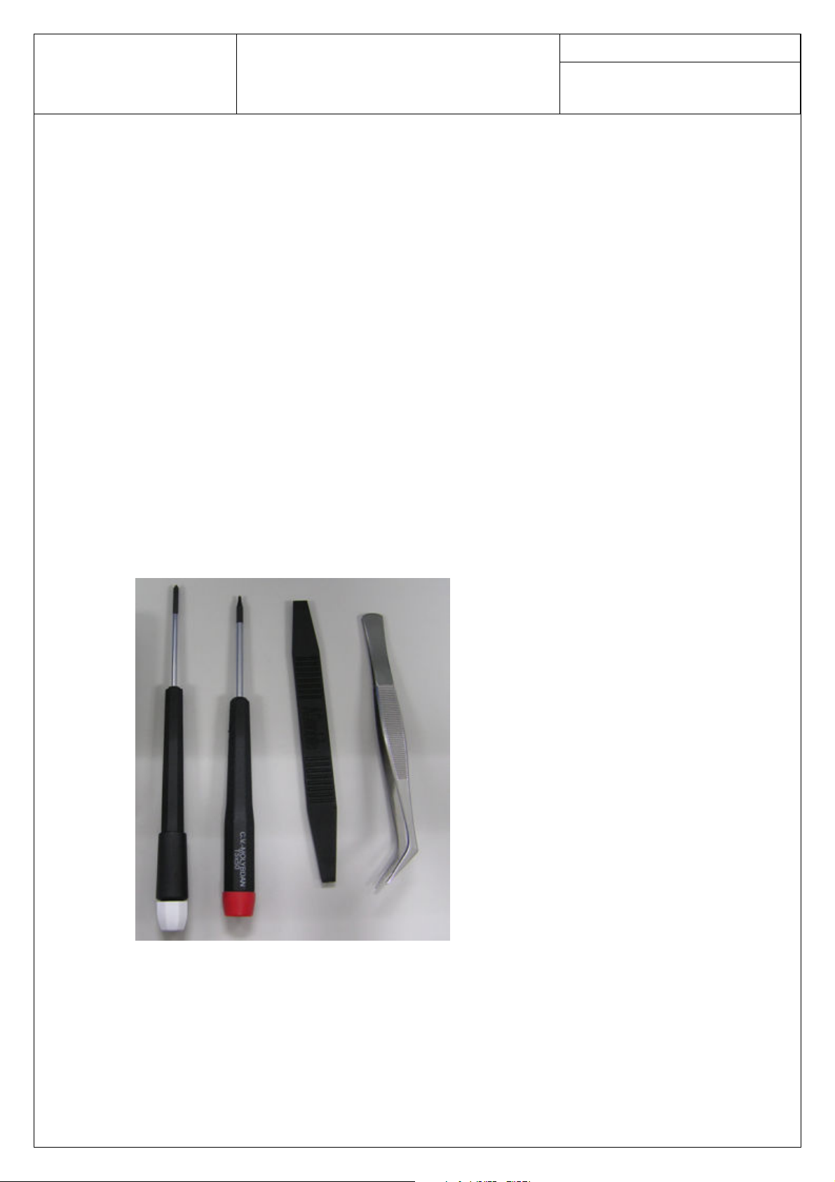
Recommended Tools
Anti-Static Mat (Ground Cord included)
Anti-Static Wrist Strap
Torque Screw Driver (T5 type, torque is set to 1.2kg-cm)
Tweezers
Plastic blade
Disassembly Procedure
The following set of diagrams will demonstrate the correct sequence and action to disassemble
P527.
ASUSTeK COMPUTER INC.
Doc. No:
Pegasus A Assembly & Disassembly
SOP
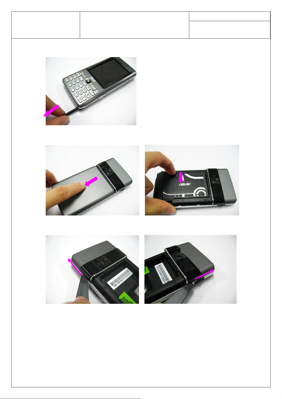
Step 1
Take the stylus away from the PDA.
Step 2
Remove the battery case and take the battery away.
Date:
Rev.: Page:
2
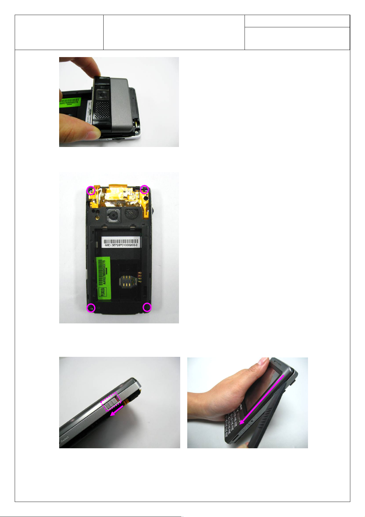
Step 3
Take off the antenna cover by plastic blade.
ASUSTeK COMPUTER INC.
Doc. No:
Pegasus A Assembly & Disassembly
SOP
Step 4
Unscrew and remove 4 screws on PDA by screw driver.
Date:
Rev.: Page:
3
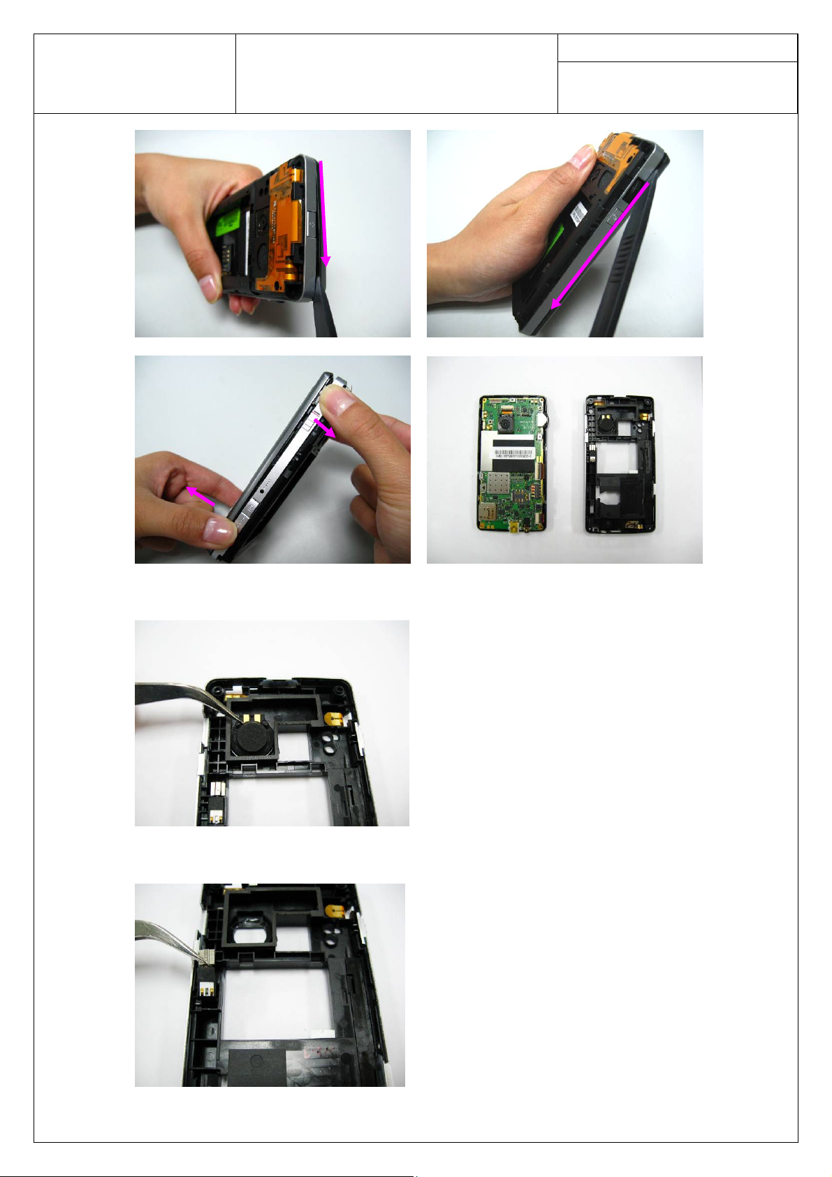
Step 5
Please switch the “Hold” key as the arrowhead shows. Then separate the middle cover from
front cover by plastic blade.
ASUSTeK COMPUTER INC.
Doc. No:
Pegasus A Assembly & Disassembly
SOP
Date:
Rev.: Page:
4
Step 6
Remove the speaker by a pair of tweezers.
Step 7
Remove the vibrator by a pair of tweezers.
ASUSTeK COMPUTER INC.
Doc. No:
Pegasus A Assembly & Disassembly
SOP
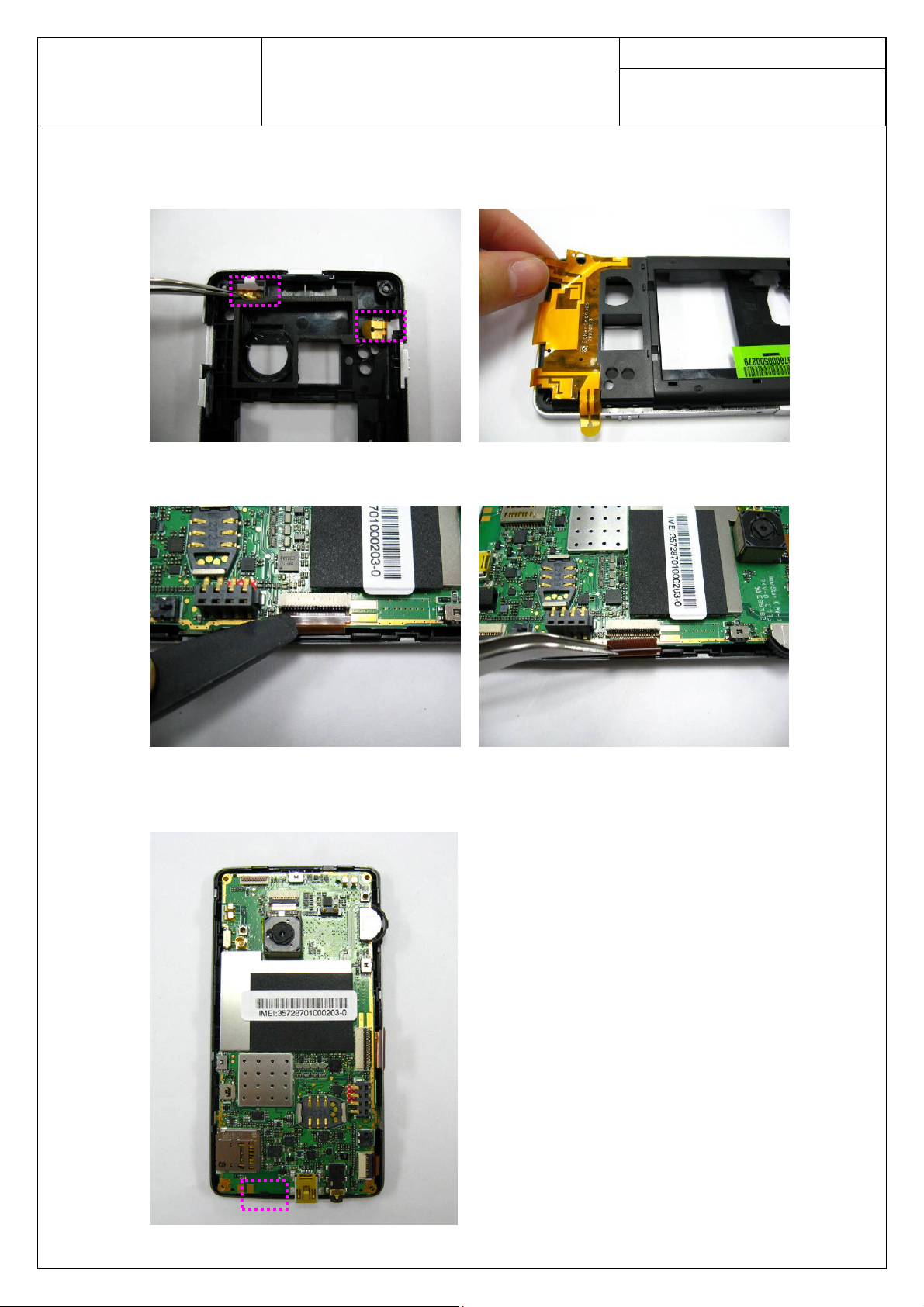
Step 8
Release the antenna FPC by a pair of tweezers. Then tear off the antenna FPC from middle
cover by hand.
Step 9
Open the LCM connector by plastic blade and release the LCM FPC by a pair of tweezers.
Date:
Rev.: Page:
5
Step 10
Separate the main board from front cover.
cover. Main board should be released from it first.
Pay attention to the hook at the bottom of the front
 Loading...