

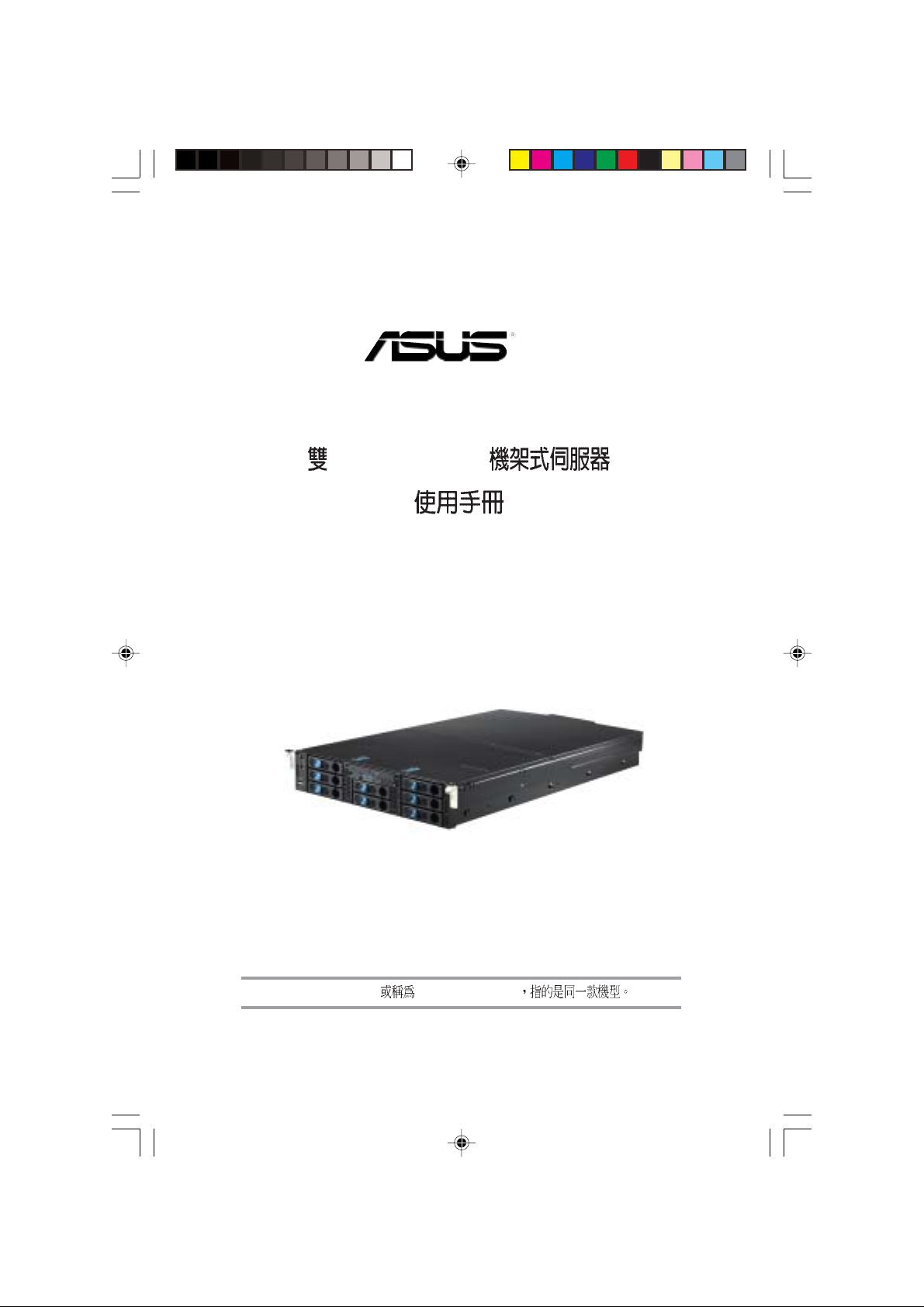
AP2400R-E2
Intel® XeonTM 2U
AP2400R-E2 ASUSPRO 2400R-E2
1) 2)
Intel Xeon Pentium Intel
Windows MS-DOS Microsoft
©2004
AP2400R-E2
V1 T1800
ASUS AP240
2004 12
2
ASUSTeK COMPUTER INC.
15
886-2-2894-3447
0800-093-456 6
AM9:00~PM12:30 PM 1:30~PM6:00
886-2-2890-7698
tw.asus.com
ASUS COMPUTER INTERNATIONAL
44370 Nobel Drive, Fremont ,CA 94538, USA
+1-510-608-4555
tmdl@asus.com
+1-502-933-8713
+1-502-995-0883
tsd@asus.com
www.asus.com
ASUS COMPUTER GmbH
Harkort Str. 25, D-40880 Ratingen, Germany
49-2102-95990
49-2102-959911
www.asuscom.de
www.asuscom.de/sales
49-2102-95990 ... /
49-2102-959910 ...
49-2102-959911
www.asuscom.de/support
ASUSTek Middle East & North Africa ( & )
P.O. Box 64133 , Dubai, U.A.E.
+9714-2831774
+9714-2831775
www.asusarabia.com
AP2400R-E2
3
........................................................................................
........................................................................................
............................................................................................
....................................................................................................
........................................................................................
2
3
7
8
9
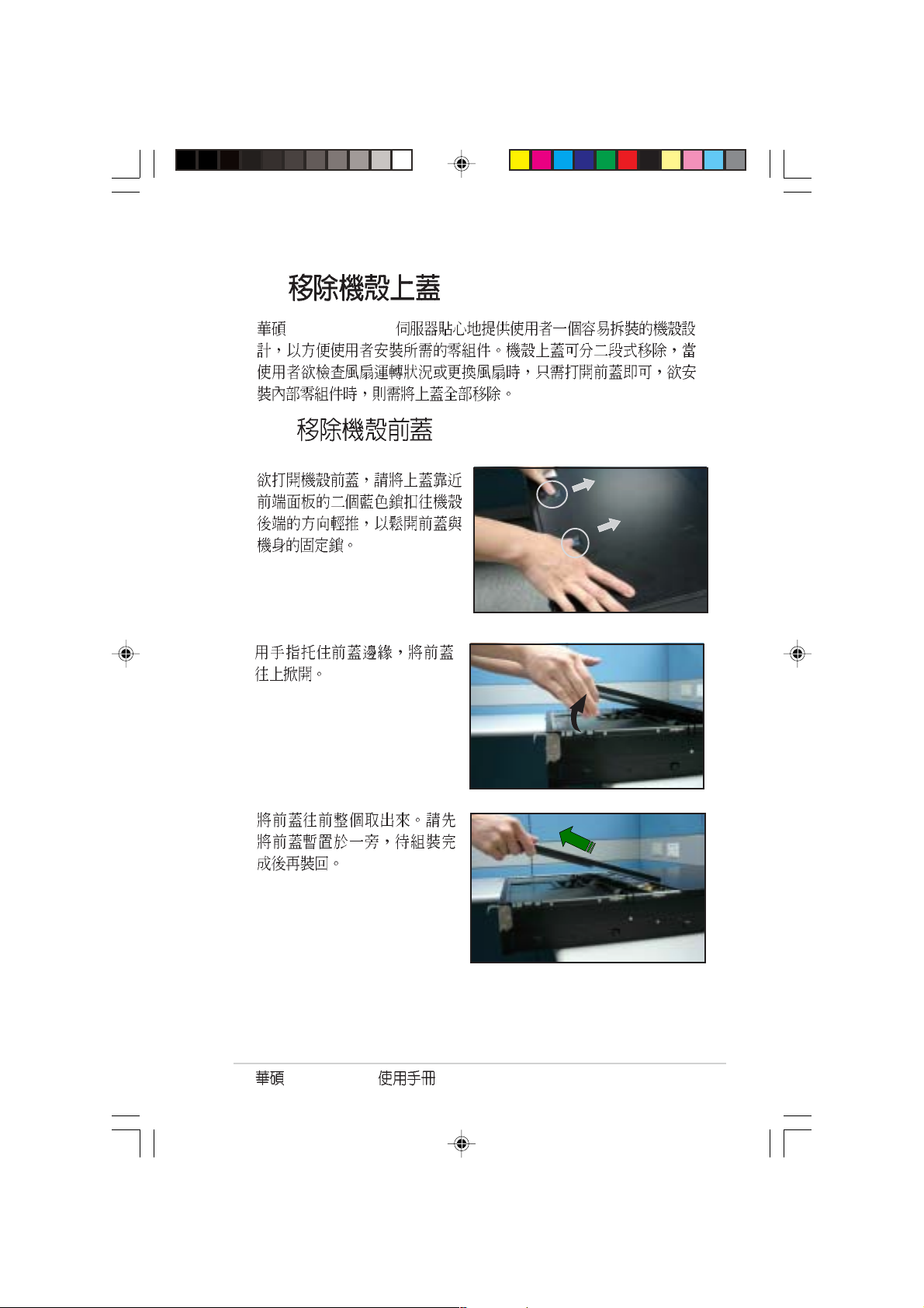
1.1
1.2
1.3
1.3.1 LED
1.4
1.5
1.6
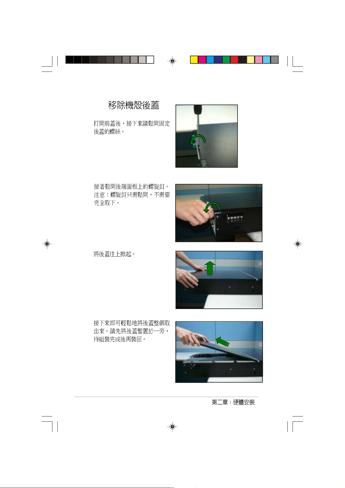
2.1
2.2
2.2.1
2.2.2
2.3 CPU
2.3.1
2.3.2
2.3.3
2.3.4 CPU
2.3.5
2.4
2.4.1
2.4.2
2.4.3
2.4.4
2.5 PCI-X
.......................................................................................
.......................................................................................
.......................................................................................
.......................................................................................
............................................................................................
..........................................................................................
..........................................................
...............................................................................
...........................................................................
...................................................................................
..........................................................
...................................................................................
...............................................................................
............................................................................
............................................................................
.....................................................................
................................................................................
........................................................................
......................................................................
................................................................................
.........................................................................
..............................................................................
......................................................................
......................................................................
ASUS AP240
....................................................................
1-1
1-2
1-3
1-4
1-4
1-6
1-7
1-8
2-1
2-2
2-3
2-3
2-4
2-5
2-5
2-6
2-6
2-8
2-9
2-10
2-10
2-11
2-12
2-12
2-13
4
2.5.1 PCI-X
2.5.2 PCI-X
2.5.3 PCI-X
2.5.4 Low-profile PCI-X
2.5.5
2.6
2.6.1
2.6.2
2.6.3
2.6.4
2.7
2.7.1
2.7.2
2.8
2.8.1 80mm
2.8.2 60mm
2.8.3
2.9
2.9.1
2.9.2
.........................................................................................
..................................................................................
2.6.4.1 Jumper
2.6.4.2
2.6.4.3 SMBUS
2.6.4.4 SCSI
2.6.4.5 SCSI ID
.....................................................................................
.................................................................................
..................................................................
..............................................................................
..................................................................
..............................................................................
..................................................................
....................................................................
..................................................................
.........................................................................
......................................................................
..........................................................
..........................................................
.............................................
.................................................................
..................................................
..............................................................
..............................................................
..............................................................
..............................................................
......................................................
..........................................................
..........................................................
2-13
2-13
2-14
2-14
2-15
2-17
2-17
2-18
2-18
2-19
2-19
2-19
2-20
2-21
2-24
2-26
2-26
2-26
2-27
2-27
2-27
2-28
2-29
2-29
2-30
3.1
3.2
3.2.1
3.2 .2
3.3
AP2400R-E2
.......................................................
...............................................................................
...................................................................................
................................................................
...........................................................................
...................................................................................
3-1
3-2
3-3
3-3
3-4
3-5
5
3.4
3.4.1
3.4.2
.............................................................
......................................................................
..............................................................................
3-10
3-10
3-11
BIOS
4.1 BIOS
4.2 BIOS
4.3 Main Menu
4.4 Advanced menu
4.5 Power menu
4.6 Boot menu
4.7 BIOS Exit menu
........................................................
............................................................
...............................................................................
..................................................................
.......................................................
.............................................................
...............................................................
.....................................................
..........................................................
5.1
5.2
5.2.1
5.2.2
5.2.3
5.2.4
5.2.5
5.3
.......................................................................................
.......................................................................................
....................................................................................
....................................................................
....................................................................
....................................................................
................................................................
...................................................................................
..........................................................
6.1
6.2
6.2.1
6.2.2 Drivers menu
6.2.3 Management Software
6.2.4 Utilities menu
6.2.5
...................................................................................
...................................................
................................................
..............................................
.............................................
........................................................................
ASUS AP240
..............................................................
........................................................................................
4-1
4-10
4-13
4-17
4-26
4-31
4-36
5-1
6-1
...............................
A-1
A-2
4-2
5-2
5-3
5-3
5-3
5-4
5-5
5-5
5-6
6-2
6-2
6-2
6-3
6-4
6-4
6-5
6
IC
AP2400R-E2
7
IC
UPS
ASUS AP240
8
1.
2.
step-by-step
AP2400R-E2
3.
4. BIOS
AP2400R-E2
AP2400R-E2
NCL-DS1R2
Jumper
BIOS BIOS
5.
6.
7.
AP2400R-E2
9
1.
2.
http://tw.asus.com
10
ASUS AP240
AP2400R-E2
1.1
AP2400R-E2
1. 2U
NCL-DS1R2
700W
x1
x1
2 CPU
6+2 SCSI
3 SCSI
2. AC
3.
AP2400R-E2 support CD ASWM
1-2
Computer Associated eTrust
4.
AP2400R-E2
Intel XeonTM
registered PC2700 DIMM DDR ECC
8 3.5 SCSI
700W
Gigabit LAN PXI-G45
LSI RAID Card (single channel) MegaRaid 320-1
LSI RAID Card (dual channel) MegaRaid 320-2
Adaptec ASR2015S Zero Channel RAID Card
1.2
2U
Socket 604 Nocona Intel® XeonTM
L2 1M 3.6GHz
PC2700 DDR 16 GB
Ultra-320 SCSI 8MB
ATI RAGE-XL VGA low-profile 64Bit /133MHz PCI-X
3 64Bit /66MHz 2 100MHz 1
133MHz PCI-X
AP2400R-E2
Microsoft Windows® 2000
Windows® Server 2003 RedHat Linux®SuSE Linux
ASWM
8
SCSI 80
AP2400R-E2
AP2400R-E2
®
ASWM
AP2400R-E2
1 19
AP2400R-E2
LED
2U
1-3
1.3
AP2400R-E2
2 USB LED
1.3.1 LED
B
6+2
LED
1-4
LED
/
RAID card SAF-TE
Location
Reset
USB
LED
Location Location
OFF
ASMS
OFF
LAN
Location
Location
LAN 1
LAN 2
AP2400R-E2
Location Location
1-5
1.4
AP2400R-E2
AP2400R-E2
1
1. 700W
3
5
9
10
11
12
6
13
14
8. PCI-X
9.
2.
3. PS/2
4.
5. USB
6.
7. low-profile PCI-X
10. PS/2
11. COM1
12.
13. Gigabit LAN1 RJ45
14. Gigabit LAN2 RJ45
15. SCSI
16. Location
LAN
ACT/LINK LED SPEED LED
17. Location
842
7
16 17
15
ACT/LINK
LED
SPEED
LED
1-6
OFF OFF 10Mbps
100Mbps
1000Mbps
LAN 2.8.2
60mm
OFF No AC-in
LAN
LAN1 LAN2
1.5
AP2400R-E2 CPU
10
7
8
11
6
4
5
3
9
1.
2.
3.
4. CPU1
5. CPU2
6. NCL-DS1R2
AP2400R-E2
1
2
7. low-profile PCI-X
8. PCI-X
9.
10.
11. PCI-X
1
1
1-7
1.6
AP2400R-E2 2U NCL-DS1R2
1MB L2 Intel® Xeon Nocona 3.
6GHz
2U
NCL-DS1R2
®
Intel
E7520 MCH
®
Intel
ICH5R Intel
®
Intel
eon Nocona 800FSB CPU L2 1M
8 184-pin PC2700 Registered
ECC DDR 16GB
Broadcom BCM5721 Gigabit LAN1 ASF2.0
Broadcom BCM5721 Gigabit LAN2
ATI RAGE-XL PCI-based VGA
SCSI 2 Ultra320 SCSI
Adaptec AIC-7902 PCI-X SCSI RAID 0,1,0+1
3 64-bit/66MHz 3V PCI-X
1 low-profile 64-bit/133MHz 3V PCI-X
2 Serial ATA150
Intel ICH5R SATA RAID 1 0
I/O 2 USB 2.0 Reset
Location
Location Message LAN x 2
I/O 1 x PS/2 1 x PS/2
1 x 1 x SCSI
1 x VGA 2 x Gigabit LAN
2 x USB 2.0 Location
Web ASWM
System Restart, ASR
700W
732.5mm x 448mm x 87.7 mm
®
PXH
Automatic
1-8
AP2400R-E2
2.1
AP2400R-E2
1.
2.
3.
4.
5. ATX
OFF
2-2
2.2
2.2.1
1.
2.
AP2400R-E2
3.
AP2400R-E2
2-3
2.2.2
1.
2.
3.
2-4
4.
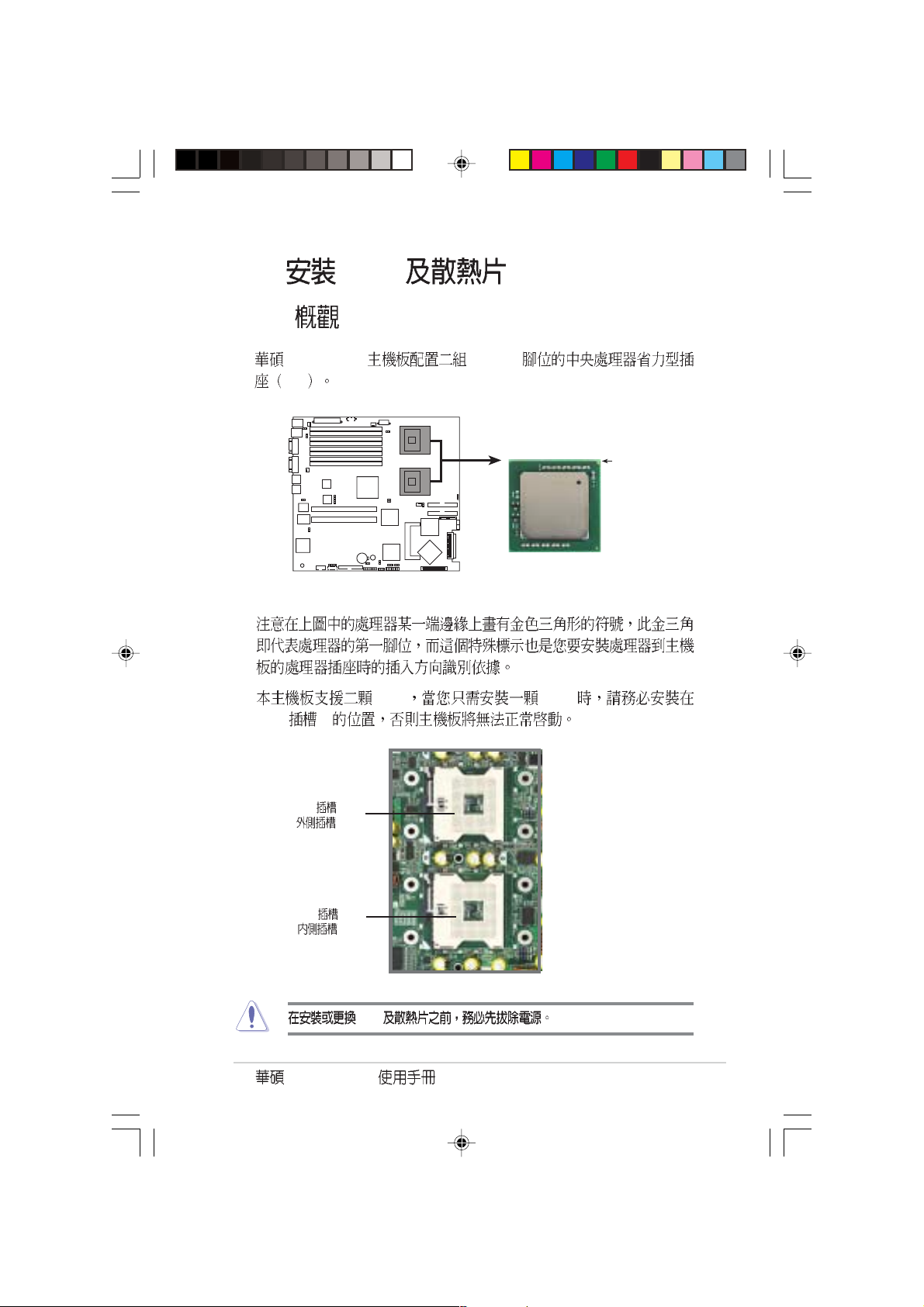
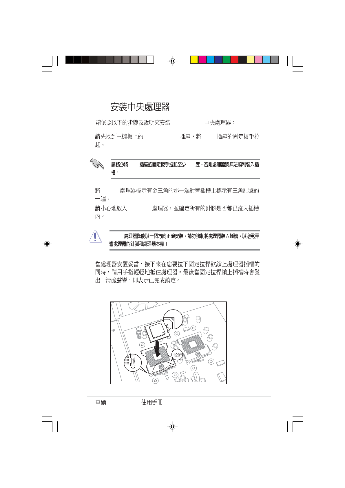
2.3 CPU
2.3.1
NCL-DS1R2 603/604
ZIF
NCL-DS1R2 CPU Socket 604
CPU CPU
CPU 1
CPU1
CPU2
Intel Xeon
®
NCL-DS1R2
Gold Arrow
Pin A1
CPU 1
( )
CPU 2
( )
CPU
AP2400R-E2
2-5
SB_PWR1
®
NCL-DS1R2
SB_PWR1
ON
Standby
Power
OFF
Powered
Off
NCL-DS1R2 Standby power LED
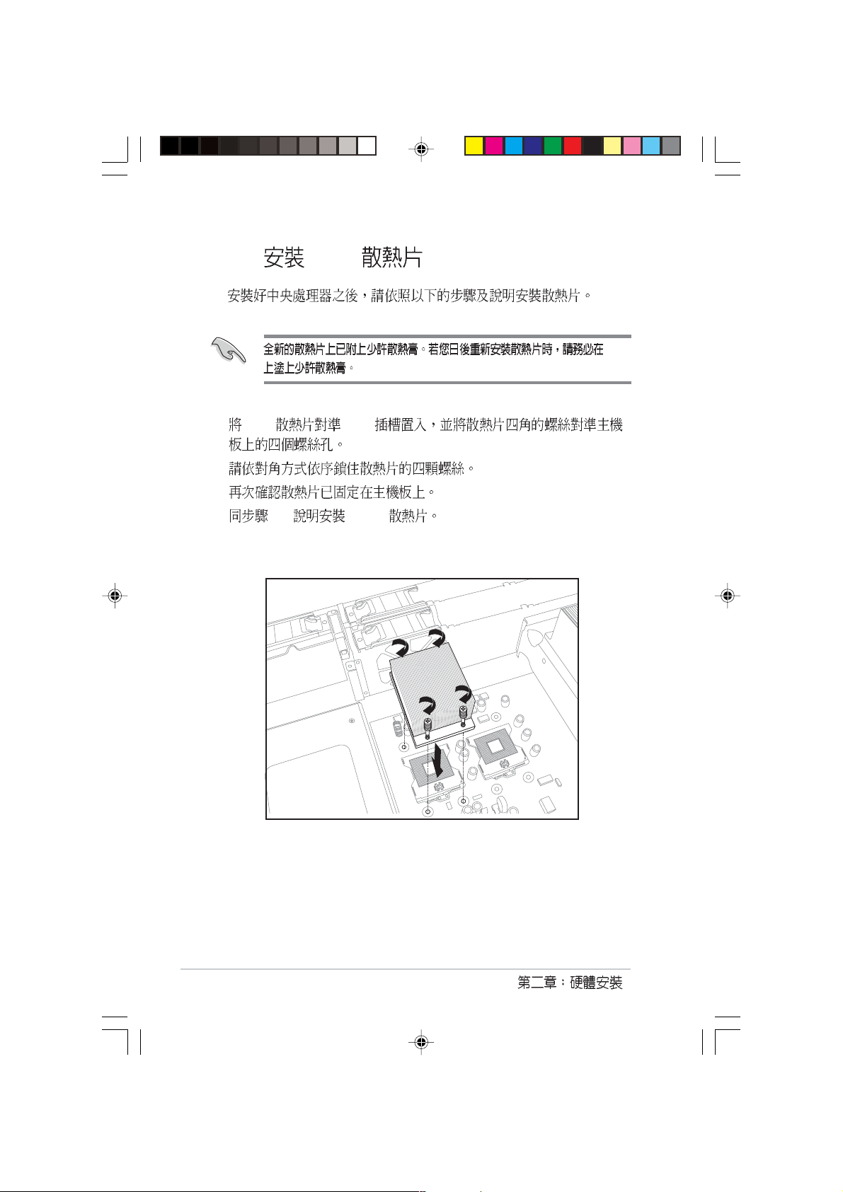
2.3.2
AP2400R-E2 CPU
CPU
80mm
2-6
2.3.3
®
Intel
XeonTM
1. 604-pin CPU CPU
CPU 115
2. XeonTM
3. XeonTM
XeonTM
4.
AP2400R-E2
2-7
2.3.4 CPU
1. CPU CPU
2.
3.
4. 1-3 CPU 2
CPU
2-8
2.3.5
CPU
1. CPU
CPU
2.
80mm
80mm
80mm
3.
AP2400R-E2
2-9
2.4
2.4.1
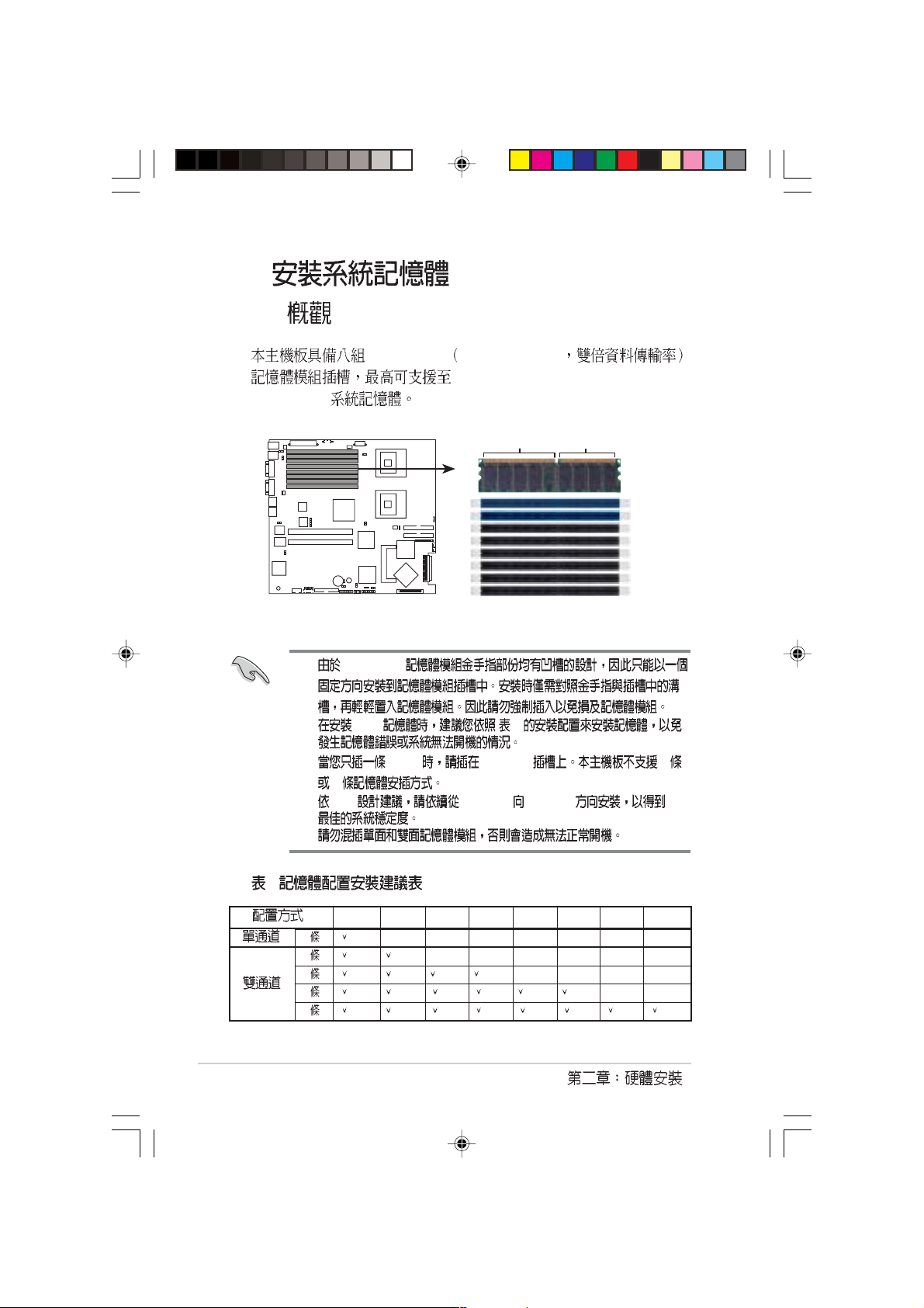
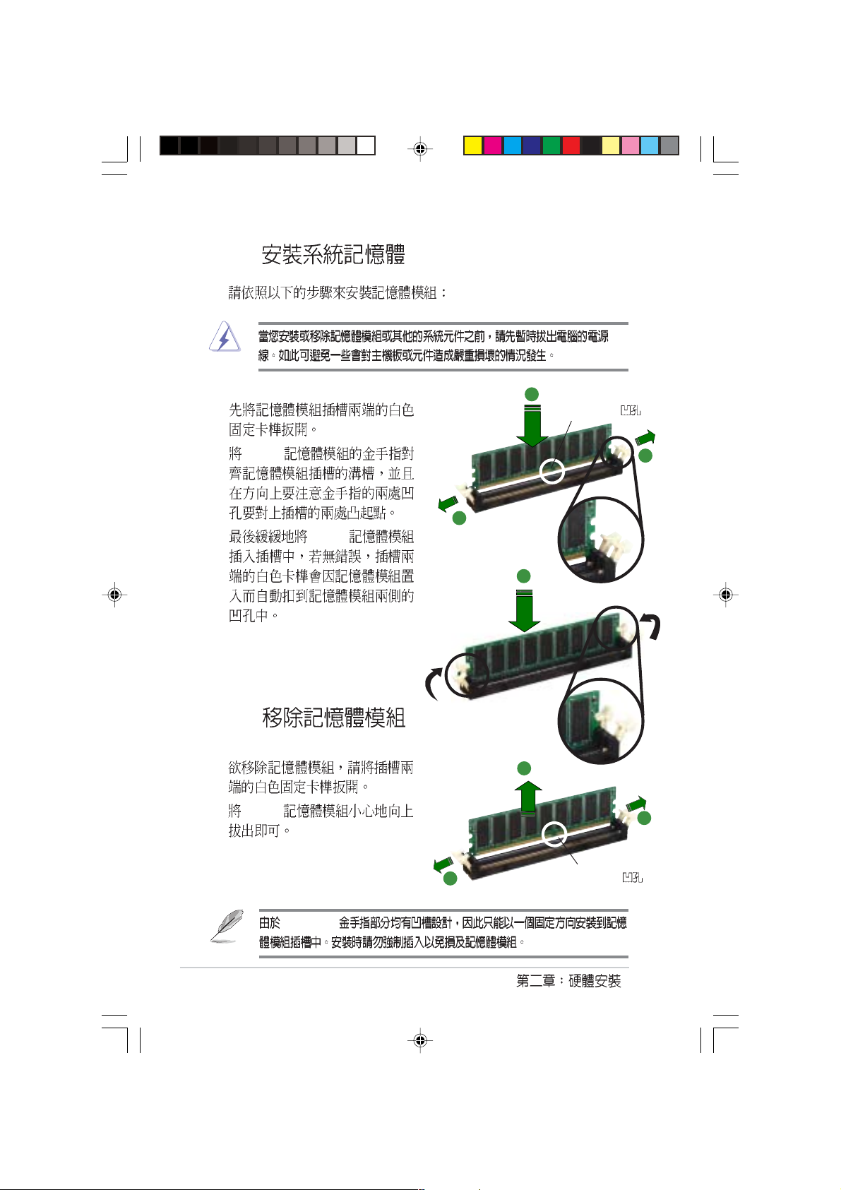
DDR DIMM
DDR DIMM Double Data Rate
16GB ECC 184-pin registered PC2700
80 Pins104 Pins
®
NCL-DS1R2
NCL-DS1R2 184-pin DDR DIMM sockets
1. DDR DIMM
2. DDR 1
3. DIMM DIMM B4 3
5
4. Intel DIMM B4 DIMM A1
5.
1
DIMM_B4 DIMM_A4 DIMM_B3 DIMM_A3 DIMM_B2 DIMM_A2 DIMM_B1 DIMM_A1
1
2
4
6
8
DIMM_B4
DIMM_A4
DIMM_B3
DIMM_A3
DIMM_B2
DIMM_A2
DIMM_B1
DIMM_A1
2-10
2.4.2
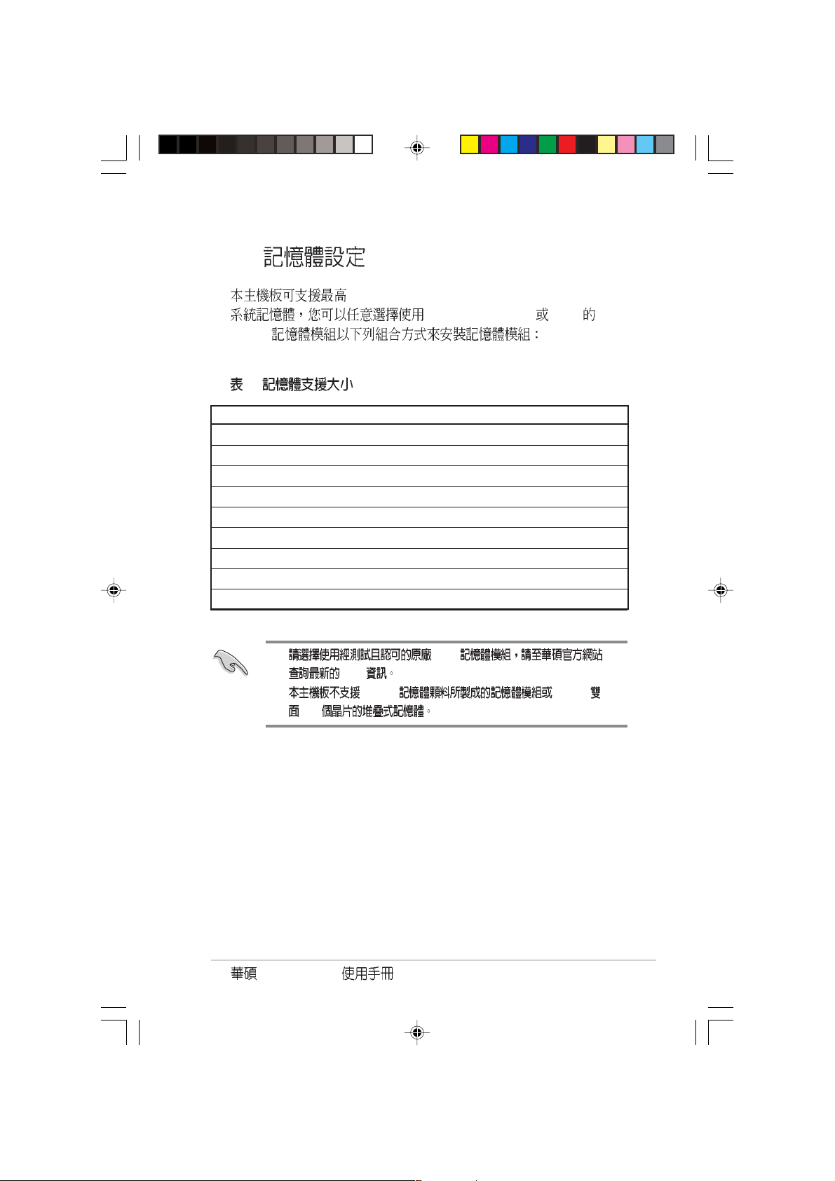
16GB ECC 184-pin registered PC2700 DDR DIMM
256, 512MB, 1GB 2GB DDR
DIMM
2
DIMM Socket 184-pin ECC DDR DIMM Total Memory
DDRA1 SDRAM 256MB, 512MB, 1GB, 2GB x1
DDRB2 SDRAM 256MB, 512MB, 1GB, 2GB x1
DDRA2 SDRAM 256MB, 512MB, 1GB, 2GB x1
DDRB2 SDRAM 256MB, 512MB, 1GB, 2GB x1
DDRA3 SDRAM 256MB, 512MB, 1GB, 2GB x1
DDRB3 SDRAM 256MB, 512MB, 1GB, 2GB x1
DDRA4 SDRAM 256MB, 512MB, 1GB, 2GB x1
DDRB4 SDRAM 256MB, 512MB, 1GB, 2GB x1
Total System Memory (Max. 16GB) = x8
1. DDR
QVL
2. 128MB 256MB
x16
AP2400R-E2
2-11
2.4.3
1.
2
DDR DIMM
2. DDR
3. DDR
2.4.4
1.
2. DDR
1
1
3
3
1
2-12
DDR DIMM
1
DDR DIMM

2.5 PCI-X
AP2400R-E2 PCI-X
64-bit 66MHz 3V PCI-X 100MHz
133MHz Low-profile 64-bit 133MHz 3V PCIX
2.5.1 PCI-X
1. PCI-X
2
2. PCI-X
3. PCI-X
1
2.5.2 PCI-X
1. PCI-X
2. PCI-X
3.
AP2400R-E2
2-13

2.5.2 .1 PCI-X
PCI-X PCI-X
PCIRS3 [4]
PCIRS2 [3]
PCIRS1 [2]
ASWM PCI 4 3 2
2.5.2 .2 PCI-X
1. R AID RAID PCIRS3
SCSI
2. PCIRS1
RJ-45
2.5.3 PCI-X
1. PCI-X
PCI-X
P5
2. PCI-X
PCI-X
3. PCI-X
2-14
PCI-X2
PCI-X2

2.5.4 Low-profile PCI-X
1. Low-profile PCI-X
PCI-X1
PCI-X
2.
PCI-X1
2.5.5
1. BIOS
BIOS
2. IRQ
3.
AP2400R-E2
2-15

IRQ
01
12
2 N/A
3* 11 COM 2
4* 12 COM 1
5* 13 LPT 2
614
7* 15 LPT 1
83 CMOS/
9* 4 ACPI
10* 5 PCI
11* 6 PCI
12* 7 PS/2
13 8
14* 9 IDE
15* 10 IDE
*
INTA INTB INTC INTD REQ# GNT#
ICH5 IDE Controller PIRQC#
ICH5 SATA Controller PIRQC#
ICH5 SMBus Controller PIRQB#
ICH5 USB UHCI Controller #1 PIRQA#
ICH5 USB UHCI Controller #2 PIRQD#
ICH5 USB 2.0 EHCI Controller PIRQH#
AIC7902 PXH2_A_0 PXH2_A_1 PXH2_A_0 PXH2_A_0
Zero Channel RAID Socket PXH2_A_2 PXH2_A_1 PXH2_A_1
ATI RAGE XL PIRQB# REQ1# GNT1#
PCI
PCIX 1 PXH1_B_0 PXH1_B_1 PXH1_B_2 PXH1_B_3 PXH1_B_0 PXH1_B_0
PCIX 2 PXH1_A_0 PXH1_A_1 PXH1_A_2 PXH1_A_3 PXH1_A_0 PXH1_A_0
2U 1 PXH1_A_0 PXH1_A_1 PXH1_A_2 PXH1_A_3 PXH1_A_0 PXH1_A_0
2U 2 PXH1_A_2 PXH1_A_3 PXH1_A_0 PXH1_A_1 PXH1_A_1 PXH1_A_1
2U 3 PXH1_A_3 PXH1_A_0 PXH1_A_1 PXH1_A_2 PXH1_A_2 PXH1_A_2
PCI Express
PCIX 4 PXH2_B_0 PXH2_B_1 PXH2_B_2 PXH2_B_3 PXH2_B_0 PXH2_B_0
PCIX 5 PXH2_B_4 PXH2_B_5 PXH2_B_6 PXH2_B_7 PXH2_B_1 PXH2_B_1
PCI 6 PIRQF# PIRQG# PIRQH# PIRQE# REQ0# GNT0#
2-16

2.6
2.6.1
1.
2.
AP2400R-E2
SCA SCSI
1
3
3.
AP2400R-E2
2
2-17

2.6.2
1.
2. SCSI
4
2-18
2.6.3
1.
2.
3.

2.6.4
AP2400R-E2 SCSI BP3LS-AR21
2.6.4.1 Jumper
Jumper
2.6.4.2
jumper
1.
2.
J1
J1J6J3
J6
J9
J3
J9
J1J6J3
J6
J9
J3
J1
J9
J1J6J3
1 2 3
J6
J9
J3
J1
J9
3.
AP2400R-E2
2-19

2.6.4.3 SMBUS
1
External
SCSI
BPSMB1
SCSI-A
NCL-DS1
SCSI-B
SMBUS
3
BPSMB1
1
8
2
SMBus
3
7
SMBus
SMBus
6
SMBus
1 2 3
2-20

2.6.4.4 SCSI
SCSI
RAID SCSI
1
SCSI
SCSI-A
NCL-DS1
SCSI-B
1
SCSI B
2
3
SCSI A
Terminator
Terminator
Terminator
1 2 3
1. SCSI SCSI
2. SCSI SCSI PXL-S30 SCSI
AP2400R-E2
2-21

ZCR RAID SCSI
SCSI
1
ZCRRAID
SCSI-A
NCL-DS1
SCSI-B
ZCR RAID
ZCR RAID
RAID
SCSI
SCSI
1
SCSI B
2
3
SCSI A
Terminator
Terminator
1 2 3
1. SCSI SCSI
2. SCSI SCSI PXL-S30 SCSI
2-22

RAID SCSI
1 SCSI-B RAID SCSI
2 External SCSI SCSI-B
SCSI SCSI
External
SCSI
RAID Card
RAID
SCSI-A
NCL-DS1
SCSI-B
1
2 3
RAID
SCSI
SCSI A
Terminator Terminator
1 2 3
SCSI SCSI
AP2400R-E2
2-23

RAID SCSI
1 SCSI-A SCSI-B SCSI
PCI RAID
2 External SCSI SCSI-B
SCSI SCSI
External
SCSI
RAID Card
Channel 1
Channel 2
RAID
SCSI-A
SCSI A
NCL-DS1
SCSI-B
13
RAID
SCSI 1
2
RAID
SCSI 2
Terminator
1 2 3
SCSI SCSI
Terminator
2-24

2.6.4.5 SCSI ID
1
1
2
3
SAF-TE ID12 ID15 ID13
4
5
6
3 2 1
1 ID4 ID8
2 ID5 ID1 ID9
3 ID6 ID2 ID10
SCSI ID7
RAID SCSI ID1...
2 3
0
1
2
8
9
10
AP2400R-E2
2-25

2.7
2.7.1
1.
2
3.
4.
5.
2.7.2
AP2400R-E2
IDE
IDE
2
3
1
4
2-26
IDE
8

2.8
AP2400R-E2 80mm
2.8.1 80mm
1.
2
3.
60mm
2.8.2 60mm
1.
2
3.
AP2400R-E2
2-27

2.8.3
REAR_FAN1
AP2400R-E2
80mm
60mm
FAN60BPC
a
1
2
FAN60M
FAN60BPC-AR21
( )
REAR_FAN2
1 2 3
4
5
FANBP-AR21
1
4
FAN60BPC
REAR_FAN2
E2-AR21 J2
FANBPC-
REAR_FAN1
FANBPC-E2-AR21
6
7
2
5
SMB
J2-
FAN60M
CPU FAN1
3
6
3
FANBP-AR21
FANBPC-AR21 80mm
7
2-28

2.9
2.9.1
AP2400R-E2 700W
1.
2. 2 2 AC
AC
P1. 24-pin ATX
P2. 12V 8-pin
P3. 80mm
P4. SMBus
P5. PCI-X
AP2400R-E2
P3
P2
P5
P4
P1 P8
P6. HDD SCSI 3
P7. HDD SCSI 2
P8. HDD SCSI 1
P9.
P9P6P7
2-29

2.9.2
(V) (V) (V) Ripple/Noise
+3.3V 3.2 3.3 3.465 50mVp-p
+5V 4.9 5 5.25 50mVp-p
+12V 11.64 12 12.6 120mVp-p
-12V -11.4 -12 -13.08 120mVp-p
+5VSB 4.85 5 5.2 70mVp-p
(A) (A) (W)
+3.3V 0.5 24 79
+5V 0.5 24 120
+12V1 0.5 12.5
+12V2 0.5 12.5
+12V3 1.5 14
+12V4 1.5 14
1. +12V1/V2/V3/V4 48A/60A
2. 3.3V/5V 140W
(OVP)
+3.3V 3.8 4.3
+5V 5.7 6.5
+12V 13.5 15
2-30
(V) (V)

Jumper

3.1
1.
2.
3.
4.
5. ATX
OFF
/
3-2
SB_PWR1
®
NCL-DS1R2
NCL-DS1R2 Standby power LED
SB_PWR1
ON
Standby
Power
OFF
Powered
Off

3.2
3.2.1
I/O
AP2400R-E2
NCL-DS1R2
3-3

3.2 .2
PS/2
T: Mouse
B: Keyboard
USB1
USB2
COM1
VGA
RJ-45
(LAN-1)
RJ-45
(LAN-2)
RAGE XL
Controller
USBPW12
AMI
8Mb
FWH
Super
I/O
ATI
VGA
SB_PWR1
REAR_FAN2
KBPWR1
REAR_FAN1
RECPVERY1
VGA_EN1
ATXPWR1
DDR DIMM_B4 (64/72 bit, 184-pin module)
DDR DIMM_A4 (64/72 bit, 184-pin module)
DDR DIMM_B3 (64/72 bit, 184-pin module)
DDR DIMM_A3 (64/72 bit, 184-pin module)
DDR DIMM_B2 (64/72 bit, 184-pin module)
DDR DIMM_A2 (64/72 bit, 184-pin module)
DDR DIMM_B1 (64/72 bit, 184-pin module)
DDR DIMM_A1 (64/72 bit, 184-pin module)
Broadcom
BCM5721
Broadcom
LAN1_EN1
BCM5721
LAN2_EN1
PCIX1 (64-bit, 133MHz 3V)
PCIX2 (64-bit, 133MHz 3V)
BPSMB1
COM2
FLOPPY1
BMCCONN1
PSUSMB1
Intel E7520
CR2032 3V
Lithium Cell
CMOS Power
33cm (13in)
CPU_FAN1
MCH
BUZZ1
CLRTC1
AUX_PANEL1
ATX12V1
USBPW34
USB34
FM_CPU1
Intel
PXH
Intel
PXH
HDLED1
mPGA 604
®
mPGA 604
J2
DSW1
SCSI_EN1
PANEL1
SEC_IDE
CPU_FAN2
FM_CPU2
PRI_IDE
Intel
ICH5R
Adaptec
AIC-7902W
34 1
NCL-DS1R2
30.5cm (12in)
SATA1
SATA2
FRNT_FAN1
FRNT_FAN2
SCSIB1
3568
SCSIA1
3-4

3.3
1. CMOS CLRTC
CMOS
CMOS
1
2 CLRTC [1-2] [2-3]
CMOS [1-2]
3
4 <Del> BIOS
BIOS
NCL-DS1R2 Clear RTC RAM
AP2400R-E2
®
NCL-DS1R2
Normal
(Default)
CLRTC1
12
23
Clear CMOS
3-5

2. USB 3-pin USBPW12, USBPW34
+5V USB S1
+5VSB S3 S4
USB
[1-2]
USBPW12
12 23
+5V +5VSB
®
NCL-DS1R2
NCL-DS1R2 USB device wake up
1. USB +5VSB
500mA/+5VSB
2.
+5VSB
3. WIndows 2000 Service Pack 4.0 S4
(Default)
USBPW34
2
1
+5V +5VSB
(Default)
3
2
+5V
3. VGA (3-pin VGA_EN1)
XL PCI VGA [1-2]
NCL-DS1R2 VGA setting
3-6
ATI RAGE-
®
NCL-DS1R2
VGA_EN1
1
Enable
(Default)
22
3
Disable

4. CPU 3-pin FM_CPU1,FM_CPU2
CPU
3-pin 4-pin CPU-FAN1 CPU_FAN2
3-pin [1-2] 4-pin
[2-3]
FM_CPU1
3
3
NCL-DS1R2 FM_CPU setting
CPU FAN
22
1
®
NCL-DS1R2
DC mode PWM
(Default)
FM_CPU2
22
1
DC mode PWM
(Default)
5. (3-pin KBPWR1)
KBPWR [2-3] +5VSB
+5VSB BIOS
®
NCL-DS1R2
NCL-DS1R2 Keyboard power setting
AP2400R-E2
<Space Bar>
KBPWR1
1
2
+5V +5VSB
(Default)
2
3
1A/
3-7

6. Gigabit LAN1 3-pin LAN1_EN1)
[1-2] Broadcom BCM5721
Gigabit LAN1 10/100/1000BASE-T
®
NCL-DS1R2
LAN1_EN1
1
Enable
(Default)
NCL-DS1R2 LAN1_EN setting
7. Gigabit LAN2 3-pin LAN2_EN1
[1-2] Broadcom BCM5721
Gigabit LAN2 10/100/1000BASE-T
®
NCL-DS1R2
NCL-DS1R2 LAN2_EN setting
LAN2_EN1
1
Enable
(Default)
3
22
Disable
3
22
Disable
3-8

8. SCSI (3-pin SCSI_EN1)
[1-2] Adaptec AIC-7902 SCSI
U320
®
NCL-DS1R2
NCL-DS1R2 SCSI setting
SCSI_EN1
12
Enable
(Default)
23
Disable
9. BIOS (3-pin RECOVERY1)
BIOS
BIOS
1 AFUDOS.EXE BIOS xxxx-xxx.
ROM
2 [2-3]
3 BIOS
4 [1-2]
5
NCL-DS1R2 BIOS recovery setting
AP2400R-E2
®
NCL-DS1R2
RECOVERY1
12
Normal BIOS Recovery
(Default)
23
3-9

3.4
3.4.1
1
2 3 645
1. PS/2 PS/2
2. PS/2 PS/2
3. USB 2.0 USB
USB 2.0
4. VGA 15-pin VGA
VGA
5. 9-pin COM1
6. RJ-45
3-10
LAN Local Area Network
ACT/LINK LED SPEED LED
OFF OFF 10Mbps
100Mbps
1000Mbps
ACT/LINK
LED
LAN
SPEED
LED

3.4.2
IDE
1. 34-1 pin FLOPPY1
®
NCL-DS1R2
NCL-DS1R2 Floppy disk drive connector
FLOPPY1
PIN 1
NOTE: Orient the red markings on
the floppy ribbon cable to PIN 1.
2. COM2 10-1 pin COM2
BIOS COM2
COM2
COM2 COM2
COM2
®
NCL-DS1R2
NCL-DS1R2 Serial port connectors
AP2400R-E2
PIN 1
3-11

3. IDE 40-1 pin PRI_IDE SEC_IDE
IDE
UltraDMA/100/66 IDE IDE
CD-ROM IDE
Master
Slave
Primary
Secondary Slave
UltraDMA/100/66 IDE
Master UltraDMA/100/66 IDE
Slave
UltraDMA/100/66
UltraDMA/100/66
1. IDE UltraDMA
2. UltraDMA/100/66
3-12
®
NCL-DS1R2
NCL-DS1R2 IDE connectors
SEC_IDE
PRI_IDE
NOTE: Orient the red markings
(usually zigzag) on the IDE
ribbon cable to PIN 1.
UltraDMA/100/66 IDE
80 IDE 80 IDE
UltraDMA/100/66
PIN 1
PIN 1

4. SMBus 5-pin PSUSMB1
SMBus System
Management Bus SMBus
+3.3V Remote Sense
NC
I2C_7_DATA#
GND
®
NCL-DS1R2
NCL-DS1R2 Power supply SMBus connector
I2C_7_CLK#
SMBus
PSUSMB1
5. SMBus 5-pin BPSMB1
SMBus System
Management Bus SMBus
NCL-DS1R2 SMBus connector
AP2400R-E2
®
NCL-DS1R2
BPSMB1
1
FAN_DC
GND
I2C_6_CLK#
I2C_6_DATA#
+5V
SCSI 1
SMBus
3-13

6. 24-pin ATXPWR1, 8-pin ATX12V1
ATX +12V
24 ATXPWR
8-pin +12V
ATX +12V +12V 8
+5VSB 2
230
300
3-14
®
NCL-DS1R2
NCL-DS1R2 ATX power connectors
ATXPWR1 ATX12V1
24-pin Power Connector
+3 Volts
+3 Volts
Ground
+5 Volts
+5 Volts
Ground
Ground
Power OK
+5V Standby
+12 Volts
+12 Volts
+3 Volts
Ground
PSON#
Ground
Ground
-5 Volts
+5 Volts
+5 Volts
+5 Volts
Ground
For Power Supply
Power Connector
+3 Volts
-12 Volts
Ground
8-pin
GND12V
GND12V
GND12V
with 24-pin
GND12V

7.
4-pin CPU_FAN1/2,
3-pin REAR_FAN1/2, FRNT_FAN1/2
350 740 8.88 1 2.2 26.64
/+12
+12V GND
NCL-DS1R2 Fan connectors
CPU_FAN1
REAR_FAN2
REAR_FAN1
®
CPU_FAN2
NCL-DS1R2
FRNT_FAN1
FRNT_FAN2
CPU_FAN1
GND
FAN Power
FAN Speed
PWM Control
REAR_FAN1
GND
+12V
Rotation
FRNT_FAN1
GND
+12V
Rotation
CPU_FAN2
GND
FAN Power
FAN Speed
PWM Control
REAR_FAN2
Rotation
+12V
GND
FRNT_FAN2
GND
+12V
Rotation
AP2400R-E2
3-15

8. Serial ATA 7-pin SATA1, SATA2
Serial ATA Serial ATA
150MB 133MB
Parallel ATA Ultra ATA/133
®
GND
GND
GND
RSATA_TXP2
RSATA_TXN2
RSATA_RXN2
NCL-DS1R2
RSATA_RXP2
SATA2 SATA1
NCL-DS1R2 SATA connectors
Serial ATA
Serial ATA
Serial ATA
Parallel ATA
RAID 0 RAID1 Serial ATA RAID
Serial ATA Windows XP Service Pack 1 Windows
2000 Service Pack 4
Serial ATA RAID RAID 0 RAID
1 Win 2000/XP/Windows Server 2003
GND
GND
GND
RSATA_TXP1
RSATA_TXN1
RSATA_RXN1
RSATA_RXP1
3-16
Serial ATA
SATA1 Master
SATA2 Slave

9. Ultra320 SCSI 68-pin SCSI-A1, SCSI-B1
68-pin Ultra320 SCSI
15 Ultra320
SCSIB1
68-Pin Ultra320/
Ultra2-Wide SCSI Connector
®
NCL-DS1R2
SCSIA1
68-Pin Ultra320/
Ultra2-Wide SCSI Connector
34 1
NCL-DS1R2 Onboard SCSI connectors
3568
SCSI
SCSI I/O
single-ended (SE) Ultra2 Ultra160 Ultra320 SCSI
Ultra320 12 25
320MB/sec SE
SE
1.5m
35
1
6834
SCSI SCSI SCSI
Ultra320 Ultra160 Ultra2 Ultra-Wide
SCSI
68-pin Internal SCSI Cable (Twisted-Pair Ribbon)
®
Internal SCSI Devices (up to 15 devices)
NCL-DS1R2
68-pin Internal SCSI Cable (Twisted-Pair Ribbon)
Internal SCSI Devices (up to 15 devices)
NCL-DS1R2 SCSI connection example
AP2400R-E2
Channel A
68-pin Female
Terminator
Channel B
68-pin Female
Terminator
3-17

10. IDE 4-pin HDLED1
SCSI RAID IDE/SATA
HDLED1
®
NCL-DS1R2
NCL-DS1R2 SCSI/SATA card activity LED connector
11. USB 2.0 10-1pin USB34
USB USB 2.0
480 Mbps USB 1.1 12 Mbps 40
5 pin
®
NCL-DS1R2
NCL-DS1R2 USB connector
SCSI_ACTLED-
SCSI_ACTLED+
1 SMBus
USB34
1
SCSI_ACTLED-
SCSI_ACTLED+
SCSI
Power
USB PortA(-)
USB PortA(+)
GND
1
NC
GND
Power
USB PortB(-)
USB PortB(+)
3-18

12. BMC 16-pin BMCCONN1
management card
®
BMCCONN1
NCL-DS1R2
ASUS server
+5VSB
+5VSB
BMC SMBCLK
12CCLK1
PSON#
BMC_RST#
PWROK
PSONEN#
NCL-DS1R2 BMC connector
13. 20-pin PANEL1
®
NCL-DS1R2
PANEL1
NCL-DS1R2 System panel connector
POWERLED+HDLED+
+5VSB
+5VSB
NCHDLED-
POWERLED-
12CDATA1
FP_PWRBTN#
BMC SMBDATA
BMC_PRESENT#
MLED-GND
NCPOWERBTN#
+5VGND
MLED+NMIBTN#
GND
BMC_SMI#
GNDNC
GNDRESETBTN#
SPKROUTGND
AP2400R-E2
3-19

3-1 pin PLED
IDE 2-pin IDE_LED
IDE_LED IDE
IDE
4-pin SPEAKER
ATX 2-pin PWRSW
BIOS
2-pin RESET
Reset
3-20

14. 20-pin PANEL1
®
I2C_4_CLK#
GNDGND
NCL-DS1R2
AUX_PANEL1
NCL-DS1R2 Auxiliary panel connector
SMB 6-1 pin FPSMB
SMBus
LAN 2-pin LAN1_LED, LAN2_LED
Gigabit LAN
NC
1
+5VSB
CASEOPEN
I2C_4_DATA#LOCATORLED1+
+5VSBLOCATORLED1-
LAN1_LINKACTLED+LOCATORBTN#
LAN1_LINKACTLED-GND
LAN2_LINKACTLED-LOCATORLED2-
LAN2_LINKACTLED+LOCATORLED2+
4-1 pin CHASSIS
Jumper Caseopen GND pin
Locator 6-pin LOCATOR
AP2400R-E2
Location
3-21

3-22

BIOS
BIOS
BIOS
BIOS

4.1 BIOS
BIOS
1. ASUS AFUDOS DOS BIOS
2. ASUS CrashFree BIOS 2 BIOS
BIOS
3. ASUS Update Windows BIOS
BIOS
BIOS AFUDOS
BIOS
4.1.1
1.
DOS
a. 1.44MB
b. DOS format A:/S Enter
Windows XP
a. 1.44MB
b. Windows /
c. 3 1/2
d. File Format Format 3 1/2
Floppy Disk
e. Create a MS-DOS startup disk
4-2
BIOS

4.1.2 AFUDOS BIOS
AFUDOS DOS BIOS
BIOS AFUDOS BIOS
BIOS
BIOS
BIOS
•
600KB
•
1. AFUDOS afudos.exe
2. DOS
afudos /o[filename]
BIOS
filename
A:\>afudos /oOLDBIOS1.ROM
3. Enter BIOS
A:\>afudos /oOLDBIOS1.ROM
AMI Firmware Update Utility - Version 1.10
Copyright (C) 2002 American Megatrends, Inc. All rights reserved.
Reading flash ..... done
A:\>
BIOS DOS
AP2400R-E2
4-3

BIOS
AFUDOS BIOS
1. tw.asus.com BIOS
BIOS
BIOS
2. AFUDOS.EXE BIOS
3. DOS
afudos /i[filename]
filename
BIOS
A:\>afudos /iNCL-DS1.ROM
4. AFUDOS BIOS
A:\>afudos /iNCL-DS1.ROM
AMI Firmware Update Utility - Version 1.10
Copyright (C) 2002 American Megatrends, Inc. All rights reserved.
Reading file ..... done
Erasing flash .... done
Writing flash .... 0x0008CC00 (9%)
BIOS
5. BIOS DOS
A:\>afudos /iNCL-DS1.ROM
AMI Firmware Update Utility - Version 1.10
Copyright (C) 2002 American Megatrends, Inc. All rights reserved.
Reading file ..... done
Erasing flash .... done
Writing flash .... 0x0008CC00 (9%)
Verifying flash .. done
A:\>
4-4
BIOS

4.1.3 CrashFree BIOS 2 BIOS
CrashFree BIOS 2 BIOS
BIOS BIOS
1. BIOS
BIOS
2. BIOS NCL-DS1.ROM
BIOS
BIOS
1.
2. BIOS
3.
BIOS
Bad BIOS checksum. Starting BIOS recovery...
Checking for floppy...
BIOS
Bad BIOS checksum. Starting BIOS recovery...
Checking for floppy...
Floppy found!
Reading file “NCL-DS1.ROM”. Completed.
Start flashing...
BIOS
4.
AP2400R-E2
4-5

BIOS
BIOS
1.
2.
3.
BIOS
Bad BIOS checksum. Starting BIOS recovery...
Checking for floppy...
Bad BIOS checksum. Starting BIOS recovery...
Checking for floppy...
Floppy not found!
Checking for CD-ROM...
CD-ROM found.
Reading file “P5GD1-VM.ROM”. Completed.
Start flashing...
4. BIOS
4-6
BIOS
BIOS BIOS
http://tw.asus.com BIOS
BIOS

4.1.4
BIOS
1. BIOS
2. BIOS
3. BIOS BIOS
4. BIOS
5. BIOS
1.
Windows
ISP
2. VX.XX.
XX
3.
BIOS
AP2400R-E2
4-7

BIOS
BIOS
1. ASUS ASUSUpdate ASUSUpdate
2. Update
BIOS from the Internet
Next
3. FTP
Auto Select
4-8
Next
BIOS

4. BIOS
Next
5.
BIOS
BIOS
BIOS BIOS
BIOS BIOS
1. ASUS
ASUSUpdate ASUSUpdate
2. Update
BIOS from a file
Next
3. BIOS
4.
BIOS
AP2400R-E2
4-9

4.2 BIOS
BIOS Basic Input and Output System
BIOS
BIOS
RUN SETUP
BIOS
BIOS
Flash ROM BIOS Flash
ROM
BIOS BIOS
BIOS
CMOS RAM
BIOS
POST Power-On Self Test
DELETE
DELETE
RESET
Ctrl + Alt + DELETE
BIOS
BIOS
4-10
1. BIOS
BIOS
4.7 BIOS Load Setup
Defaults
2. BIOS
3. http://tw.asus.com BIOS
BIOS
BIOS

4.2.1 BIOS
System Time [11:10:19]
System Date [Fri 08/06/2004]
Legacy Diskette A [1.44M, 3.5 in]
Primary IDE Master : [ST320413A]
Primary IDE Slave : [ASUS CD-S520/A]
Third IDE Master : [Not Detected]
Third IDE Slave : [Not Detected]
Fourth IDE Master : [Not Detected]
Fourth IDE Slave : [Not Detected]
IDE Configuration
System Information
4.2.2
BIOS
Main
Advanced
Power
Boot
Exit BIOS
Use [ENTER], [TAB] or
[SHIFT-TAB] to select
a field.
Use [+] or [-] to
configure the System
time.
4.2.3
AP2400R-E2
4-11

4.2.4
Main
Advanced Power Boot Exit
4.2.5
4.2.6
System Time [11:51:19]
System Date [Thu 05/0 7/2004]
Legacy Diskette A [1.44M, 3.5 in]
Primary IDE Master : [ST320413A]
Primary IDE Slave : [ASUS CD-S520/A
Third IDE Master : [Not Detected]
Third IDE Slave : [Not Detected]
Fourth IDE Master : [Not Detected]
Fourth IDE Slave : [Not Detected]
IDE Configuration
System Information
Enter
Advanced PCI/PnP Settings
WARNING: Setting wrong values in
below sections may cause system to
malfunction.
Plug And Play O/S [No]
PCI Latency Timer [64]
Allocate IRQ to PCI VGA [Yes]
Palette Snooping [Disabled]
PCI IDE BusMaster [Enabled]
Use [ENTER],
[TAB] or [SHIFTTAB] to select a
field.
Use [+] or [-] to
configure the
System time.
4.2.7
4.2.8
4.2.9
4-12
Enter
PageUp PageDown
BIOS

4.3 Main Menu
BIOS
4.2.1 BIOS
System Time [11:10:19]
System Date [Fri 08/06/2004]
Legacy Diskette A [1.44M, 3.5 in]
Primary IDE Master : [ST320413A]
Primary IDE Slave : [ASUS CD-S520/A]
Third IDE Master : [Not Detected]
Third IDE Slave : [Not Detected]
Fourth IDE Master : [Not Detected]
Fourth IDE Slave : [Not Detected]
IDE Configuration
System Information
Use [ENTER], [TAB] or
[SHIFT-TAB] to select
a field.
Use [+] or [-] to
configure the System
time.
4.3.1 System Time [XX:XX:XXXX]
00 23 00 59 00 59 Tab
Tab + Shift
4.3.2 System Date [Day XX/XX/XXXX]
1 12 1 31 2099 Tab Tab
+ Shift
4.3.3 Legacy Diskette A [1.44M, 3.5 in.]
[Disabled] [360K, 5.
25 in.] [1.2M, 5.25 in.] [720K, 3.5 in.] [1.44M, 3.5 in.] [2.88M, 3.5 in.]
AP2400R-E2
4-13

4.3.4 IDE Primary, Third and
Fourth IDE Master/Slave
BIOS IDE
IDE
Enter
Primary IDE Master
Device : Hard Disk
Vendor : ST320413A
Size : 20.0GB
LBA Mode : Supported
Block Mode : 16 Sectors
PIO Mode : Supported
Async DMA : MultiWord DMA-2
Ultra DMA : Ultra DMA-5
SMART Monitoring : Supported
Type [Auto]
LBA/Large Mode [Auto]
Block(Multi-sector Transfer)[Auto]
PIO Mode [Auto]
Smart Monitoring [Auto]
32Bit Data Transfer [Disabled]
Select the type of
device connected to
the system.
Device Vendor Size LBA Mode Block
Mode PIO Mode Async DMA Ultra DMA SMART monitoring
BIOS N/A
Type [Auto]
IDE Auto
IDE CDROM IDE
ARMD ATAPI IDE
ZIP LS-120 MO [Not
Installed] [Auto] [CDROM] [ARMD]
LBA/Large Mode [Auto]
LBA [Auto]
LBA LBA
[Disabled] [Auto]
4-14
BIOS

Block (Multi-sector Transfer) [Auto]
[Auto]
[Disabled]
[Disabled] [Auto]
PIO Mode [Auto]
PIO [Auto] [0] [1] [2] [3] [4]
DMA Mode [Auto]
DMA [Auto] [SWDMA0] [SWDMA1] [SWDMA2]
[MWDMA0] [MWDMA1] [MWDMA2] [UDMA0] [UDMA1] [UDMA2]
[UDMA3] [UDMA4] [UDMA5] [UDMA6]
SMART Monitoring [Auto]
Smart Monitoring, Analysis,
and Reporting Technology [Auto] [Disabled] [Enabled]
32Bit Data Transfer [Disabled]
32 [Disabled] [Enabled]
4.3.5 IDE IDE Configuration
IDE
Enter
IDE Configuration
Onboard IDE Operate Mode [Enhanced Mode]
Enhanced Mode Support On [S-ATA]
Configure S-ATA as RAID [No]
IDE Detect Time Out (Sec) [35]
When in AHCI/RAID
mode SATA controller
is forced to Native
mode.
Onboard IDE Operate Mode [Enhanced Mode]
MS-DOS Windows 98SE/ME [Compatible Mode]
Windows 2000/XP [Enhanced Mode]
[Compatible Mode] [Enhanced Mode]
AP2400R-E2
4-15

Enhanced Mode Support On [S-ATA mode]
[S-ATA]
ATA ATA
DOS Windows 98SE/ME ATA
ATA
[P-ATA+S-ATA] [P-ATA]
[S-ATA]
[P-ATA+S-ATA] [S-ATA Mode] [P-ATA]
Configure S-ATA as RAID [No]
S-ATA IDE No RAID Yes
[Yes] [No]
IDE Detect Time Out [35]
ATA/ATAPI
[0] [5] [10] [15] [20] [25] [30] [35]
4.3.6 System Information
BIOS
MS-
AMIBIOS
Version : 08.00.10
Build Date : 07/23/04
Processor
Type : Intel(R) Xeon(TM) CPU 2.80GHz
Speed : 2800 MHz
Count : 2
System Memory
Size : 512MB
AMI BIOS
Processor
System Memory
4-16
BIOS
BIOS

4.4 Advanced menu
USB Configuration
MPS Configuration
Remote Access Configuration
CPU Configuration
Chipset
Onboard Devices Configuration
PCI PnP
Configure the USB
support.
4.4.1 USB USB Configuration
USB
USB Configuration
Module Version - 2.23.2-5.3
USB Devices Enabled: None
USB Function [8 USB Ports]
Legacy USB Support [Auto]
USB 2.0 Controller [Enabled]
USB 2.0 Controller Mode [HiSpeed]
USB Function [Enabled]
USB Mass Storage Device Configuration
USB [Disabled] [Enabled]
Enables USB host
controllers.
AP2400R-E2
4-17

USB Function [4 USB Ports]
USB [Diabled] [2 USB
Ports] [4 USB Ports]
Legacy USB Support [Auto]
USB [Auto]
USB
USB [Disabled]
USB USB
[Disabled] [Enabled] [Auto]
USB 2.0 Controller [Enabled]
USB 2.0 [Diabled]
[Enabled]
USB 2.0 Controller MODE [HiSpeed]
USB 2.0 HiSpeed
480 Mbps Full Speed 12 Mbps [HiSpeed] [Full
Speed]
USB
4-18
USB Mass Storage Device Configuration
USB Mass Storage Reset Delay [20 Seconds]
No USB Mass Storage device detected
Device #1 N/A
Emulation Type [N/A]
Device #2 N/A
Emulation Type [N/A]
Device #3 N/A
Emulation Type [N/A]
Device #4 N/A
Emulation Type [N/A]
Device #5 N/A
Emulation Type [N/A]
Device #6 N/A
Emulation Type [N/A]
BIOS

USB Mass Storage Reset Delay [20 Sec]
BIOS USB
[10 Sec ] [20 Sec] [30 Sec] [40 Sec]
Emulation Type [Auto]
USB Device #
Emulation Type Auto
530MB USB
530MB Forced FDD
[Auto] [Floppy] [Forced FDD]
[Hard Disk] [CDROM]
4.2.1 BIOS
4.4.2 MPS MPS Configuration
USB
MPS Configuration
MPS Revision [1.4]
MPS Revision [1.4]
AP2400R-E2
Enables USB host
controllers.
[1.1] [1.4]
4-19

4.4.3 Remote Access
Configuration
Configure Remote Access type and parameters
Remote Access [Enabled]
Enables USB host
controllers.
Remote Access [Disabled]
[Disabled]
[Enabled]
4.4.4 CPU Configuration
Configure Advanced CPU settings
Manufacturer: Intel
Brand String: Intel(R) Xeon (TM) CPU 2.80GHz
Frequency : 2800 MHz
FSB Speed : 800 MHz
Ratio Status: Unlocked
Ratio Actual Value : 14
Ratio CMOS Setting: [ 8]
Hyper Threading Technology [Enabled]
Max CPUID Value Limit: [Disabled]
Enhanced C1 Control [Auto]
CPU Internal Thermal Control [Auto]
Sets the ratio between
CPU Core Clock and the
FSB Frequency.
NOTE: If an invalid
ratio is set in CMOS
then actual and
setpoint values may
differ.
Ratio CMOS Setting [8]
BIOS
Hyper Threading Technology [Enabled]
Hyper Threading
[Disabled] [Enabled] Hyper-Threading
Intel Pentium 4
4-20
BIOS

Max CPUID Value Limit [Disabled]
CPUID
[Enabled] [Disabled] [Enabled]
Enhanced C1 Control [Auto]
[Auto] BIOS CPU C1E
C1E CPU CPU idle
[Auto][Disabled]
CPU Internal Thermal Control [Auto]
[Auto] BIOS CPU
[Auto][Disabled]
4.4.5 Chipset
Enter
Advanced Chipset Settings
Warning: Setting wrong values in below sections may
cause system to malfunction.
NorthBridge Configuration
Onboard LAN Boot ROM [Enabled]
Onboard SCSI Boot ROM [Enabled]
OnBoard LAN Boot ROM [Enabled]
ROM [Disabled] [Enabled]
OnBoard SCSI Boot ROM [Disabled]
SCSI Boot
ROM [Disabled] [Enabled]
AP2400R-E2
Enable or disable
DRAM timing.
Boot
4-21

NorthBridge Chipset Configuration
DIMM Speed: DDR2 400
Memory Remap Feature [Enabled]
DIMM Speed
DIMM
Memory Remap Feature [Enabled]
[Enabled]
[Disabled]
4-22
BIOS

4.4.6 OnBoard Devices
Configuration
Configure Win627EHF Super IO Chipset
Serial Port1 Address [3F8/IRQ4]
Serial Port2 Address [2F8/IRQ3]
Serial Port2 Mode [Normal]
Parallel Port Address [378]
Onboard Game/MIDI Port [Disabled]
Serial Port1 Address [3F8/IRQ4]
COM 1 [Disabled] [3F8/
IRQ4] [3E8/IRQ4] [2E8/IRQ3]
Serial Port2 Address [2F8/IRQ3]
COM 2 [Disabled] [2F8/
IRQ3] [3E8/IRQ4] [2E8/IRQ3]
Serial Port2 Mode [Normal]
COM 2 [Normal]
[IrDA] [ASK IR]
Enable or disable
Azalia controller.
Parallel Port Address [Disabled]
[278] [3BC]
AP2400R-E2
[Disabled] [378]
4-23

4.4.7 PCI PCI PnP
PCI/PnP PCI/PnP
IRQ DMA
Advanced PCI/PnP Settings
WARNING: Setting wrong values in below sections
may cause system to malfunction.
Plug And Play O/S [No]
PCI Latency Timer [64]
Allocate IRQ to PCI VGA [Yes]
Palette Snooping [Disabled]
PCI IDE BusMaster [Enabled]
OffBoard PCI/ISA IDE Card [Auto]
IRQ-3 assigned to [PCI Device]
IRQ-4 assigned to [PCI Device]
IRQ-5 assigned to [PCI Device]
IRQ-7 assigned to [PCI Device]
IRQ-9 assigned to [PCI Device]
IRQ-10 assigned to [PCI Device]
IRQ-11 assigned to [PCI Device]
IRQ-14 assigned to [PCI Device]
NO: Lets the BIOS
configue all the
devices in the system.
YES: Lets the
operating system
configure Plug and
Play (PnP) devices not
required for boot if
your system has a Plug
and Play operating
system.
Plug and Play O/S [No]
[No] BIOS
[Yes] [No] [Yes]
PCI Latency Timer [64]
PCI [32] [64]
[96] [128] [160] [192] [224] [248]
Allocate IRQ to PCI VGA [Yes]
PCI IRQ
[Yse] BIOS PCI IRQ
[No] [Yes]
Palette Snooping [Disabled]
VGA [Disabled]
[Disabled] [Enabled]
4-24
MPEG
[Enabled]
BIOS

PCI IDE BusMaster [Enabled]
BIOS PCI
IDE [Disabled] [Enabled]
OffBoard PCI/ISA IDE Card [Auto]
PCI IDE PCI
[Auto] [PCI Slot1] [PCI Slot2] [PCI Slot3] [PCI Slot4] [PCI Slot5] [PCI
Slot6]
IRQ-xx assigned to [PCI Device]
[PCI Device] IRQ PCI/PnP
[Reserved] IRQ ISA
[PCI Device] [Reserved]
IRQ-15 assigned to [PCI Device]
DMA Channel 0 [PCI Device]
DMA Channel 1 [PCI Device]
DMA Channel 3 [PCI Device]
DMA Channel 5 [PCI Device]
DMA Channel 6 [PCI Device]
DMA Channel 7 [PCI Device]
Reserved Memory Size [Disabled]
DMA Channel X assigned to [PCI Device]
[PCI Device] DMA channel PCI/PnP
[Reserved] DMA channel legacy ISA
[PCI Device] [Reserved]
Reserved Memory Size [Disabled]
[Disabled] [16k] [32k]
[64k]
AP2400R-E2
4-25

4.5 Power menu
APM
ACPI APIC Support [Enabled]
APM Configuration
Hardware Monitor
Select the ACPI state
used for System
Suspend.
4.5.1 ACPI APIC Support [Enabled]
ACPI APIC RSDT
[Disabled] [Enabled]
4.5.2 APM Configuration
APM Configuration
Power Management/APM [Enabled]
Video Power Down Mode [Disabled]
Hard Disk Power Down Mode [Disabled]
Standby Time Out [Disabled]
Suspend Time Out [Disabled]
Throttle Slow Clock Ratio [50%]
Power Button Mode [On/Off]
Restore on AC Power Loss [Last State]
Power On By PS/2 Keyboard [Disabled]
Power On By PS/2 Mouse [Disabled]
Power On Ring [Disabled]
Power On By PME# [Disabled]
Power On By RTC Alarm [Disabled]
Power On By PS/2 Keyboard [Disabled]
Power On By PS/2 Mouse [Disabled]
<Enter> to select
whether or not to
restart the system
after AC power loss.
Power Management [Enabled]
[Disabled] [Enabled]
Video Power Down Mode [Suspend]
[Suspend]
4-26
[Disabled][Standby]
BIOS

Hard Disk Power Down Mode [Suspend]
[Disabled]
[Standby][Suspend]
Standby Time Out [Disabled]
[Disabled] [1
Min] [2 Min] [4 Min][8 Min] [10 Min] [20 Min] [30 Min] [40 Min] [50 Min]
[60 Min]
Suspend Time Out [Disabled]
[Disabled] [1
Min] [2 Min] [4 Min][8 Min] [10 Min] [20 Min] [30 Min] [40 Min] [50 Min]
[60 Min]
Throttle Slow Clock Ratio [50%]
throttle [87.5%] [75.
0%] [62.5%] [50.0%] [37.5%] [25.0%] [12.5%]
Power Button Mode [On/Off]
On/Off
[On/Off] [Suspend]
Restore on AC Power Loss [Last State]
[Power Off]
[Power On]
[Last State]
[Power Off] [Power On] [Last State]
Power On By PS/2 Keyboard [Disabled]
ATX 1 5VSB
[Disabled] [Enabled]
Power On By PS/2 Mouse [Disabled]
[Enabled] PS2
ATX 1 5VSB
[Disabled] [Enabled]
AP2400R-E2
4-27

Power On Ring [Disabled]
[Enabled]
Power On By PME# [Disabled]
[Enabled] PME
[Disabled] [Enabled]
Power On By RTC Alarm [Disabled]
(RTC) [Enabled]
RTC Alarm Date RTC Alarm Hour RTC Alarm Minute RTC
Alarm Second
[Disabled] [Enabled]
[Disabled]
4-28
BIOS

4.5.3 Hardware Monitor
Hardware Monitor
CPU Temperature [51ºC/122.5ºF]
MB Temperature [41ºC/105.5ºF]
CPU Fan Speed [3813 RPM]
CPU Q-Fan Control [Disabled]
Chassis Fan Speed [N/A]
VCORE Voltage [ 1.320V]
3.3V Voltage [ 3.345V]
5V Voltage [ 5.094V]
12V Voltage [11.880V]
VBAT Voltage [ 3.088V]
12V Voltage [11.749V]
CPU1/CPU2 Temperature [xxx /xxx ]
MB Temperature [xxx /xxx ]
CPU1/CPU2 Fan Speed [xxxxRPM] or [N/A]
Front1/Front2 Fan Speed [xxxxRPM] or [N/A]
Rear1/Rear2 Fan Speed [xxxxRPM] or [N/A]
RPM Rotations Per Minute
AP2400R-E2
4-29

Smart Fan Control [Disabled]
[Disabled] [Enabled]
Smart Fan Control [Enabled] CPU1 Temperature CPU2
Temperature MB Temperature
Smart Fan Control [Enabled]
CPU1 Temperature [055]
CPU2 Temperature [055]
MB Temperature [050]
VCORE1 Voltage [ 1.356V]
VCORE2 Voltage [ 1.358V]
CPU1/CPU2 Temperature [xxx]
MB Temperature [xxx]
VCORE1 Voltage, VCORE1 Voltage, 3.3V Voltage, 5V
Voltage, 5VSB Voltage, VBAT Voltage, 12V Voltage
CPU
4-30
BIOS
 Loading...