

Page 1
AP2400R-E2
®®
®
Dual IntelDual Intel
Dual Intel
Dual IntelDual Intel
800 MHz Front Side Bus800 MHz Front Side Bus
800 MHz Front Side Bus
800 MHz Front Side Bus800 MHz Front Side Bus
Service Guide
®®
Xeon™ 2U Rackmount Server Xeon™ 2U Rackmount Server
Xeon™ 2U Rackmount Server
Xeon™ 2U Rackmount Server Xeon™ 2U Rackmount Server
Page 2

E1800E1800
E1800
E1800E1800
First edition V1First edition V1
First edition V1
First edition V1First edition V1
June 2005June 2005
June 2005
June 2005June 2005
Copyright © 2005 ASUSTeK COMPUTER INC. All Rights Reserved.Copyright © 2005 ASUSTeK COMPUTER INC. All Rights Reserved.
Copyright © 2005 ASUSTeK COMPUTER INC. All Rights Reserved.
Copyright © 2005 ASUSTeK COMPUTER INC. All Rights Reserved.Copyright © 2005 ASUSTeK COMPUTER INC. All Rights Reserved.
No part of this manual, including the products and software described in it, may be reproduced,
transmitted, transcribed, stored in a retrieval system, or translated into any language in any form
or by any means, except documentation kept by the purchaser for backup purposes, without the
express written permission of ASUSTeK COMPUTER INC. (“ASUS”).
ASUS provides this manual “as is” without warranty of any kind, either express or implied,
including but not limited to the implied warranties or conditions of merchantability or fitness for
a particular purpose. In no event shall ASUS, its directors, officers, employees, or agents be liable
for any indirect, special, incidental, or consequential damages (including damages for loss of
profits, loss of business, loss of use or data, interruption of business and the like), even if ASUS
has been advised of the possibility of such damages arising from any defect or error in this
manual or product.
Specifications and information contained in this manual ae furnished for informational use only,
and are subject to change at any time without notice, and should not be construed as a
commitment by ASUS. ASUS assumes no responsibility or liability for any errors or inaccuracies
that may appear in this manual, including the products and software described in it.
Product warranty or service will not be extended if: (1) the product is repaired, modified or
altered, unless such repair, modification of alteration is authorized in writing by ASUS; or (2) the
serial number of the product is defaced or missing.
Products and corporate names appearing in this manual may or may not be registered
trademarks or copyrights of their respective companies, and are used only for identification or
explanation and to the owners’ benefit, without intent to infringe.
iiii
ii
iiii
Page 3

Contents
Notices ................................................................................................ vi
Safety information ............................................................................. vii
About this guide ............................................................................... viii
Chapter 1: Product introductionChapter 1: Product introduction
Chapter 1: Product introduction
Chapter 1: Product introductionChapter 1: Product introduction
1.1 System package contents .................................................... 1-2
1.2 System specifications .......................................................... 1-3
1.2 System specifications .......................................................... 1-4
1.3 Front panel features ............................................................. 1-5
1.4 Rear panel features .............................................................. 1-5
1.5 Internal features ................................................................... 1-6
1.6 LED information .................................................................... 1-7
1.6.1 Front panel LEDs .................................................... 1-7
1.6.2 Rear fan LEDs ......................................................... 1-8
1.6.3 System fan LED ...................................................... 1-8
1.6.4 Power supply LED ................................................... 1-9
1.6.5 LAN port LEDs ........................................................ 1-9
Chapter 2: Hardware setupChapter 2: Hardware setup
Chapter 2: Hardware setup
Chapter 2: Hardware setupChapter 2: Hardware setup
2.1 Chassis cover ....................................................................... 2-2
2.1.1 Removing the front bezel ....................................... 2-2
2.1.2 Removing the top cover ......................................... 2-3
2.1.3 Installing the top cover .......................................... 2-5
2.1.4 Removing the air duct ............................................ 2-6
2.1.5 Installing the air duct .............................................. 2-6
2.2 Central Processing Unit (CPU) .............................................. 2-8
2.2.1 Removing the CPU heatsink .................................... 2-8
2.2.2 Installing a CPU ....................................................... 2-9
2.2.3 Installing the CPU heatsink ................................... 2-12
2.3 System memory ................................................................. 2-13
2.3.1 Memory configurations ......................................... 2-13
2.3.2 Installing a DIMM ................................................... 2-14
2.3.3 Removing a DIMM ................................................. 2-14
2.4 Hard disk drives .................................................................. 2-15
2.5 Expansion cards .................................................................. 2-17
2.5.1 Installing a low-profile expansion card .................. 2-17
2.5.2 Installing a full-length expansion card .................. 2-18
2.5.3 ZCR socket ........................................................... 2-21
2.5.4 Configuring an expansion card.............................. 2-22
iiiiii
iii
iiiiii
Page 4

Contents
2.6 Cable connections .............................................................. 2-23
2.6.1 Motherboard ......................................................... 2-24
2.6.2 SCSI backplanes .................................................... 2-25
2.6.3 SCSI HDD configurations ....................................... 2-26
2.6.4 SCSI ID assignments ............................................. 2-29
2.6.5 SCSI jumper settings ............................................ 2-29
2.6.6 SMBus and backplane power cabling .................... 2-30
2.6.7 Fan boards ............................................................ 2-31
2.7 Removable components ..................................................... 2-33
2.7.1 Hot-swap mid-fans (80mm) ................................. 2-33
2.7.2 Rear fans (60mm) ................................................ 2-34
2.7.3 Power supply modules .......................................... 2-34
2.7.4 Slim optical and floppy drives ............................... 2-35
2.7.5 Front panel LED and switch board ........................ 2-36
2.7.6 SCSI backplanes .................................................... 2-36
Chapter 3:Chapter 3:
Chapter 3:
Chapter 3:Chapter 3:
3.1 Rackmount rail kit items ....................................................... 3-2
3.2 Attaching the rails to the server .......................................... 3-3
3.3 Attaching the rack rails ........................................................ 3-4
3.4 Rackmounting the server ..................................................... 3-6
Chapter 4:Chapter 4:
Chapter 4:
Chapter 4:Chapter 4:
4.1 Motherboard layout .............................................................. 4-2
4.2 Jumpers ................................................................................ 4-4
4.3 Connectors ........................................................................... 4-9
Chapter 5:Chapter 5:
Chapter 5:
Chapter 5:Chapter 5:
5.1 Managing and updating your BIOS ........................................ 5-2
5.1.1 Creating a bootable floppy disk .............................. 5-2
5.1.2 AFUDOS utility ........................................................ 5-3
5.1.3 ASUS CrashFree BIOS 2 utility ................................ 5-6
5.1.4 ASUS Update utility ................................................ 5-8
Installation optionsInstallation options
Installation options
Installation optionsInstallation options
Motherboard infoMotherboard info
Motherboard info
Motherboard infoMotherboard info
BIOS informationBIOS information
BIOS information
BIOS informationBIOS information
iviv
iv
iviv
5.2 BIOS setup program ........................................................... 5-11
5.2.1 BIOS menu screen ................................................. 5-12
5.2.2 Menu bar ............................................................... 5-12
5.2.3 Navigation keys .................................................... 5-12
5.2.4 Menu items ........................................................... 5-13
5.2.5 Sub-menu items ................................................... 5-13
Page 5

Contents
5.2.6 Configuration fields .............................................. 5-13
5.2.7 Pop-up window ..................................................... 5-13
5.2.8 Scroll bar .............................................................. 5-13
5.2.9 General help .......................................................... 5-13
5.3 Main menu .......................................................................... 5-14
5.3.1 System Time ......................................................... 5-14
5.3.2 System Date ......................................................... 5-14
5.3.3 Legacy Diskette A ................................................5-14
5.3.4 Primary/Secondary IDE Master/Slave,
Third and Fourth IDE/SATA ..................................5-15
5.3.5 IDE Configuration .................................................. 5-17
5.3.6 System Information ..............................................5-18
5.4 Advanced menu .................................................................. 5-19
5.4.1 USB Configuration................................................. 5-19
5.4.2 MPS Configuration ................................................ 5-21
5.4.3 Remote Access Configuration .............................. 5-22
5.4.4 CPU Configuration ................................................. 5-24
5.4.5 Chipset ................................................................. 5-25
5.4.6 Onboard Devices Configuration ............................5-27
5.4.7 PCI PnP ................................................................. 5-28
5.5 Power menu ........................................................................ 5-30
5.5.1 ACPI APIC Support ................................................ 5-30
5.5.2 APM Configuration ................................................ 5-30
5.5.3 Hardware Monitor ................................................. 5-33
5.6 Boot menu .......................................................................... 5-35
5.6.1 Boot Device Priority .............................................. 5-35
5.6.2 Boot Settings Configuration ................................. 5-36
5.6.3 Security ................................................................ 5-37
5.7 Exit menu ........................................................................... 5-40
Appendix:Appendix:
Appendix:
Appendix:Appendix:
A.1 Power supply ........................................................................ A-2
A.1.1 General description ................................................. A-2
ReferencesReferences
References
ReferencesReferences
A.1.2 Specifications ......................................................... A-3
A.2 Qualified Vendors List (QVL) ............................................... A-4
A.3 Troubleshooting ................................................................... A-6
A.4 NCL-DS1R2 block diagram.................................................... A-8
vv
v
vv
Page 6

Notices
Federal Communications Commission StatementFederal Communications Commission Statement
Federal Communications Commission Statement
Federal Communications Commission StatementFederal Communications Commission Statement
This device complies with Part 15 of the FCC Rules. Operation is subject to
the following two conditions:
•
This device may not cause harmful interference, and
•
This device must accept any interference received including interference
that may cause undesired operation.
This equipment has been tested and found to comply with the limits for a
Class B digital device, pursuant to Part 15 of the FCC Rules. These limits
are designed to provide reasonable protection against harmful interference
in a residential installation. This equipment generates, uses and can radiate
radio frequency energy and, if not installed and used in accordance with
manufacturer’s instructions, may cause harmful interference to radio
communications. However, there is no guarantee that interference will not
occur in a particular installation. If this equipment does cause harmful
interference to radio or television reception, which can be determined by
turning the equipment off and on, the user is encouraged to try to correct
the interference by one or more of the following measures:
•
Reorient or relocate the receiving antenna.
•
Increase the separation between the equipment and receiver.
•
Connect the equipment to an outlet on a circuit different from that to
which the receiver is connected.
•
Consult the dealer or an experienced radio/TV technician for help.
WARNING!WARNING!
WARNING! The use of shielded cables for connection of the monitor to
WARNING!WARNING!
the graphics card is required to assure compliance with FCC regulations.
Changes or modifications to this unit not expressly approved by the
party responsible for compliance could void the user’s authority to
operate this equipment.
Canadian Department of Communications StatementCanadian Department of Communications Statement
Canadian Department of Communications Statement
Canadian Department of Communications StatementCanadian Department of Communications Statement
This digital apparatus does not exceed the Class B limits for radio noise
emissions from digital apparatus set out in the Radio Interference
Regulations of the Canadian Department of Communications.
This class B digital apparatus complies with Canadian ICES-003.This class B digital apparatus complies with Canadian ICES-003.
This class B digital apparatus complies with Canadian ICES-003.
This class B digital apparatus complies with Canadian ICES-003.This class B digital apparatus complies with Canadian ICES-003.
vivi
vi
vivi
Page 7
Safety information
Electrical safetyElectrical safety
Electrical safety
Electrical safetyElectrical safety
• Before installing or removing signal cables, ensure that the power cables
for the system unit and all attached devices are unplugged.
• To prevent electrical shock hazard, disconnect the power cable from the
electrical outlet before relocating the system.
• When adding or removing any additional devices to or from the system,
ensure that the power cables for the devices are unplugged before the
signal cables are connected. If possible, disconnect all power cables from
the existing system before you add a device.
• If the power supply is broken, do not try to fix it by yourself. Contact a
qualified service technician or your dealer.
Operation safetyOperation safety
Operation safety
Operation safetyOperation safety
• Any mechanical operation on this server must be conducted by certified
or experienced engineers.
• Before operating the server, carefully read all the manuals included with
the server package.
• Before using the server, make sure all cables are correctly connected and
the power cables are not damaged. If any damage is detected, contact
your dealer as soon as possible.
• To avoid short circuits, keep paper clips, screws, and staples away from
connectors, slots, sockets and circuitry.
• Avoid dust, humidity, and temperature extremes. Place the server on a
stable surface.
This product is equipped with a three-wire power cable and plug for the
user’s safety. Use the power cable with a properly grounded electrical
outlet to avoid electrical shock.
Lithium-Ion Battery WarningLithium-Ion Battery Warning
Lithium-Ion Battery Warning
Lithium-Ion Battery WarningLithium-Ion Battery Warning
CAUTION!CAUTION!
CAUTION! Danger of explosion if battery is incorrectly replaced.
CAUTION!CAUTION!
Replace only with the same or equivalent type recommended by the
manufacturer. Dispose of used batteries according to the
manufacturer’s instructions.
CD-ROM Drive Safety WarningCD-ROM Drive Safety Warning
CD-ROM Drive Safety Warning
CD-ROM Drive Safety WarningCD-ROM Drive Safety Warning
CLASS 1 LASER PRODUCTCLASS 1 LASER PRODUCT
CLASS 1 LASER PRODUCT
CLASS 1 LASER PRODUCTCLASS 1 LASER PRODUCT
Heavy SystemHeavy System
Heavy System
Heavy SystemHeavy System
CAUTION!CAUTION!
CAUTION! This server system is heavy. Ask for assistance when
CAUTION!CAUTION!
moving or carrying the system.
viivii
vii
viivii
Page 8

About this guide
AudienceAudience
Audience
AudienceAudience
This user guide is intended for system integrators and experienced users
with at least basic knowledge of configuring a server.
ContentsContents
Contents
ContentsContents
This guide contains the following parts:
1.1.
Chapter 1: Product IntroductionChapter 1: Product Introduction
1.
Chapter 1: Product Introduction
1.1.
Chapter 1: Product IntroductionChapter 1: Product Introduction
This chapter describes the general features of the barebone server,
including sections on the front panel and rear panel specifications.
2.2.
Chapter 2: Hardware setupChapter 2: Hardware setup
2.
Chapter 2: Hardware setup
2.2.
Chapter 2: Hardware setupChapter 2: Hardware setup
This chapter lists the hardware setup procedures that you have to
perform when installing or removing system components.
3.3.
Chapter 3: Installation optionsChapter 3: Installation options
3.
Chapter 3: Installation options
3.3.
Chapter 3: Installation optionsChapter 3: Installation options
This chapter describes how to prepare the barebone server for rack
mounting.
4.4.
Chapter 4: Motherboard informationChapter 4: Motherboard information
4.
Chapter 4: Motherboard information
4.4.
Chapter 4: Motherboard informationChapter 4: Motherboard information
This chapter gives information about the motherboard that comes
with the server. This chapter includes the motherboard layout, jumper
settings, and connector locations.
5.5.
Chapter 5: BIOS informationChapter 5: BIOS information
5.
Chapter 5: BIOS information
5.5.
Chapter 5: BIOS informationChapter 5: BIOS information
This chapter tells how to change the system settings through the
BIOS Setup menus. Detailed descriptions of the BIOS parameters are
also provided.
7.7.
Appendix: ReferencesAppendix: References
7.
Appendix: References
7.7.
Appendix: ReferencesAppendix: References
This appendix includes additional information that you may refer to
when configuring your barebone server.
viiiviii
viii
viiiviii
Page 9

ConventionsConventions
Conventions
ConventionsConventions
To make sure that you perform certain tasks properly, take note of the
following symbols used throughout this manual.
WARNING: WARNING:
WARNING: Information to prevent injury to yourself when trying
WARNING: WARNING:
to complete a task.
CAUTION:CAUTION:
CAUTION: Information to prevent damage to the components
CAUTION:CAUTION:
when trying to complete a task.
IMPORTANT: IMPORTANT:
IMPORTANT: Instructions that you MUST follow to complete a
IMPORTANT: IMPORTANT:
task.
NOTE: NOTE:
NOTE: Tips and information to aid in completing a task.
NOTE: NOTE:
ReferenceReference
Reference
ReferenceReference
Visit the ASUS websites worldwide that provide updated information for all
ASUS hardware and software products. Refer to the ASUS contact
information for details.
ixix
ix
ixix
Page 10

xx
x
xx
Page 11

Chapter 1
This chapter describes the general
features of the barebone server,
including sections on the front
panel and rear panel specifications.
ASUS AP2400R-E2ASUS AP2400R-E2
ASUS AP2400R-E2
ASUS AP2400R-E2ASUS AP2400R-E2
Product introduction
1-1
Page 12

1.1 System package contents
Check your system package for the following items.
ChassisChassis
Chassis ASUS AR21 2U rackmount chassis
ChassisChassis
MotherboardMotherboard
Motherboard ASUS NCL-DS1R2 motherboard
MotherboardMotherboard
ComponentsComponents
Components 700W redundant power supply, 115V~230V
ComponentsComponents
Slim optical drive|
Slim floppy disk drive
Chassis fan
HDD fan
Hot-swap SCSI HDD trays
SCSI backplanes
Front bezel
CPU heatsink (2 pcs.)
CablesCables
Cables RJ-45 extension connector
CablesCables
AC power cable
System cables
AccessoriesAccessories
Accessories Rackmount rail kit
AccessoriesAccessories
AP2400R-E2 user guide
AP2400R-E2 support CD (includes ASWM*)
CA eTrust Anti-virus CD
AR21 chassis ears (left, right)
Thermal grease strip
Bag of screws
*ASUS System Web-based Management
If any of the above items is damaged or missing, contact your retailer.
1-21-2
1-2
1-21-2
Chapter 1: Product introductionChapter 1: Product introduction
Chapter 1: Product introduction
Chapter 1: Product introductionChapter 1: Product introduction
Page 13
1.2 System specifications
The ASUS AP2400R-E2 is a 2U barebone server system featuring the ASUS
NCL-DS1R2 motherboard. The server supports dual Intel® Xeon™
processors with EM64T technology, plus other latest technologies through
the chipsets onboard.
ChassisChassis
Chassis
ChassisChassis
MotherboardMotherboard
Motherboard
MotherboardMotherboard
ChipsetChipset
Chipset
ChipsetChipset
CPUCPU
CPU
CPUCPU
MemoryMemory
Memory
MemoryMemory
LANLAN
LAN
LANLAN
VGAVGA
VGA
VGAVGA
SCSISCSI
SCSI
SCSISCSI
ExpansionExpansion
Expansion
ExpansionExpansion
slotsslots
slots
slotsslots
Rackmount 2U (AR21)
ASUS NCL-DS1R2
North Bridge: Intel
South Bridge: Intel® 82801ER
I/O Bridge: Intel® 6700PXH Bridge
Supports dual Intel
1 MB and 2 MB caches via two 604-pin sockets
8 x 184-pin DDR sockets for up to 16 GB system memory
Supports PC2700 registered ECC DDR DIMMs
2 x Broadcom® BCM5721 PCI Express Gigabit LAN
controllers
ATI RAGE-XL PCI-based VGA controller
Supports 8MB display memory
Adaptec® AIC-7902W Ultra320 Dual-channel SCSI controller
3 x full-length 64-bit/66MHz 3V PCI-X slots (on a riser card)
1 x low-profile 64-bit/133MHz 3V PCI-X slot
®
E7520 MCH
®
Xeon™ 3.6 GHz processors with L2
StorageStorage
Storage
StorageStorage
Front panelFront panel
Front panel
Front panelFront panel
Rear panelRear panel
Rear panel
Rear panelRear panel
8 x 3.5-inch hot-swappable HDD bays
1 x slim optical drive
1 x slim 1.44MB floppy drive
2 x USB 2.0 ports
Power switch
Reset switch
Location switch
Power, HDD access, location, message, LAN
HDD LEDs: Status, activity
1 x PS/2 keyboard port
1 x PS/2 mouse port
1 x Serial port
1 x VGA port
2 x USB 2.0 ports
2 x RJ-45 ports (with LEDs)
1 x external SCSI port (alternative)
(continued on the next page)
ASUS AP2400R-E2ASUS AP2400R-E2
ASUS AP2400R-E2
ASUS AP2400R-E2ASUS AP2400R-E2
1-31-3
1-3
1-31-3
Page 14

1.2 System specifications
ManagementManagement
Management
ManagementManagement
HardwareHardware
Hardware
HardwareHardware
monitorsmonitors
monitors
monitorsmonitors
Power supplyPower supply
Power supply
Power supplyPower supply
DimensionsDimensions
Dimensions
DimensionsDimensions
Refer to “Chapter 4 Motherboard information” for details on the internal
connectors.
ASUS Server Web-based Management (ASWM)
Voltage, temperature, and fan speed monitoring
Automatic System Restart (ASR) feature
700W redundant power supply, 115V~230V, 50Hz~60Hz
732.5mm (l) x 448mm (w) x 87.7mm (h)
1-41-4
1-4
1-41-4
Chapter 1: Product introductionChapter 1: Product introduction
Chapter 1: Product introduction
Chapter 1: Product introductionChapter 1: Product introduction
Page 15
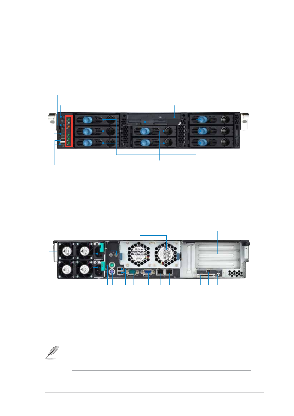
1.3 Front panel features
The barebone server displays a simple yet stylish front panel with easily
accessible features. The power and reset buttons, LED indicators, location
switch, slim optical and floppy drives, and two USB ports are located on the
front panel.
Reset buttonReset button
Reset button
Reset buttonReset button
Location switchLocation switch
Location switch
Location switchLocation switch
Power buttonPower button
Power button
Power buttonPower button
Front panel LEDsFront panel LEDs
Front panel LEDs
Front panel LEDsFront panel LEDs
USB 2.0 portsUSB 2.0 ports
USB 2.0 ports
USB 2.0 portsUSB 2.0 ports
Slim floppy driveSlim floppy drive
Slim floppy drive
Slim floppy driveSlim floppy drive
Hot-swappable HDD baysHot-swappable HDD bays
Hot-swappable HDD bays
Hot-swappable HDD baysHot-swappable HDD bays
Slim optical driveSlim optical drive
Slim optical drive
Slim optical driveSlim optical drive
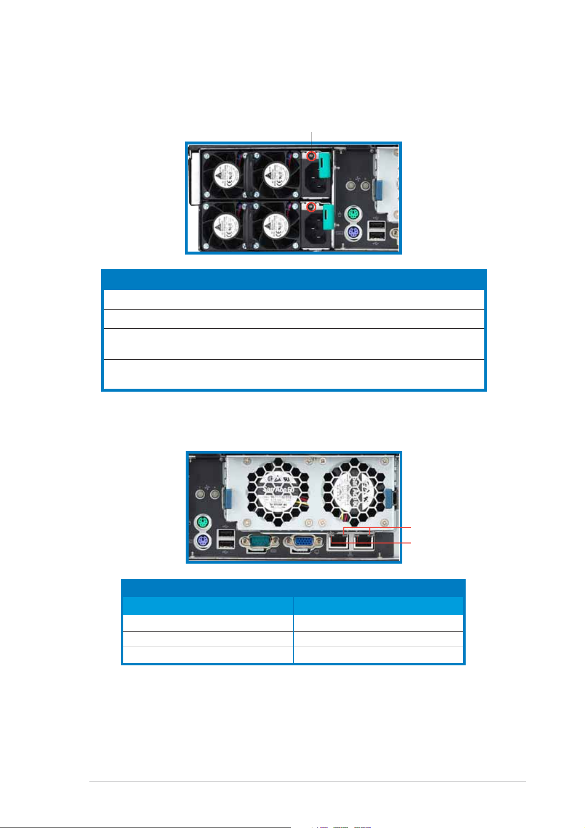
1.4 Rear panel features
The rear panel includes the expansion slots, LAN, VGA, and I/O ports, fans,
and the system power sockets.
Redundant powerRedundant power
Redundant power
Redundant powerRedundant power
supply modulessupply modules
supply modules
supply modulessupply modules
Rear fansRear fans
Rear fans
Rear fansRear fans
status LEDsstatus LEDs
status LEDs
status LEDsstatus LEDs
Rear fansRear fans
Rear fans
Rear fansRear fans
Expansion slotsExpansion slots
Expansion slots
Expansion slotsExpansion slots
AC power sockets
AC power socketsAC power sockets
AC power socketsAC power sockets
When disconnecting LAN cables, you need to remove the rear fan cage.
Refer to section “2.7 Removable components” for instructions on
removing the fan cage.
ASUS AP2400R-E2ASUS AP2400R-E2
ASUS AP2400R-E2
ASUS AP2400R-E2ASUS AP2400R-E2
USB 2.0 ports
Serial port
USB 2.0 portsUSB 2.0 ports
USB 2.0 portsUSB 2.0 ports
PS/2 keyboard port
PS/2 mouse port
PS/2 keyboard portPS/2 keyboard port
PS/2 keyboard portPS/2 keyboard port
PS/2 mouse portPS/2 mouse port
PS/2 mouse portPS/2 mouse port
VGA port
Serial portSerial port
Serial portSerial port
VGA portVGA port
VGA portVGA port
Gigabit LAN1 port
Gigabit LAN2 port
Gigabit LAN1 portGigabit LAN1 port
Gigabit LAN1 portGigabit LAN1 port
Gigabit LAN2 portGigabit LAN2 port
Gigabit LAN2 portGigabit LAN2 port
port (alternative)
External SCSI
Location switch
port (alternative)port (alternative)
port (alternative)port (alternative)
External SCSIExternal SCSI
External SCSIExternal SCSI
Location switchLocation switch
Location switchLocation switch
Location LED
Location LEDLocation LED
Location LEDLocation LED
1-51-5
1-5
1-51-5
Page 16
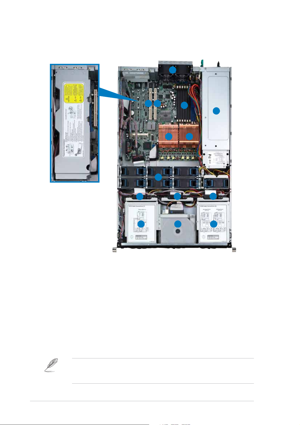
1.5 Internal features
The barebone system includes the basic components as shown.
11
1
11
22
33
2
3
22
33
44
4
44
55
5
55
PCI-X card cagePCI-X card cage
PCI-X card cage
PCI-X card cagePCI-X card cage
99
9
99
11
22
1
2
11
22
1. 2 x rear fans
2. 64-bit PCI-X slots
(underneath the PCI-X card
cage)
3. Low profile PCI-X slot
4. 8 x DDR DIMM sockets
5. Power supply cage
6. CPU2 socket with heatsink
66
6
66
88
8
88
1010
10
1010
11
1
11
77
7
77
1111
11
1111
11
33
3
33
44
1
4
11
44
8. 7 x system fans
9. SCSI backplane 1
10. SCSI backplane 2
11. SCSI backplane 3
12. 3 x HDD bays
13. Top: Slim optical drive
Mid: Slim floppy drive
Bottom: 2 x HDD bays
1-61-6
1-6
1-61-6
7. CPU1 socket with heatsink
The air duct lies on top of the motherboard components. Remove the air
duct to access the components. Refer to section “2.1.4 Removing and
installing the air duct” for instructions.
14. 3 x HDD bays
Chapter 1: Product introductionChapter 1: Product introduction
Chapter 1: Product introduction
Chapter 1: Product introductionChapter 1: Product introduction
Page 17
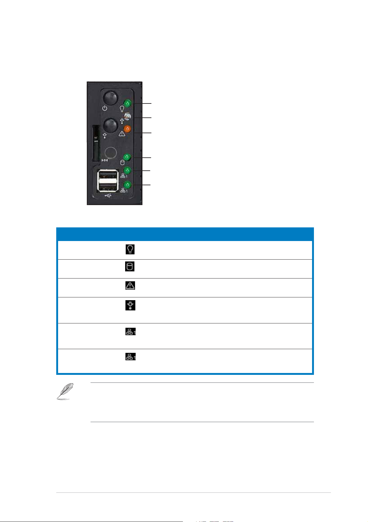
1.6 LED information
1.6.11.6.1
1.6.1
1.6.11.6.1
LEDLED
LED
LEDLED
Front panel LEDsFront panel LEDs
Front panel LEDs
Front panel LEDsFront panel LEDs
Power LEDPower LED
Power LED
Power LEDPower LED
Location LEDLocation LED
Location LED
Location LEDLocation LED
Message LEDMessage LED
Message LED
Message LEDMessage LED
Storage Access LEDStorage Access LED
Storage Access LED
Storage Access LEDStorage Access LED
LAN1 LEDLAN1 LED
LAN1 LED
LAN1 LEDLAN1 LED
LAN2 LEDLAN2 LED
LAN2 LED
LAN2 LEDLAN2 LED
IconIcon
Icon
IconIcon
Display statusDisplay status
Display status
Display statusDisplay status
DescriptionDescription
Description
DescriptionDescription
Power LED ON System power ON
Storage Access LED OFF No activity
Blinking Read/write data into the HDD
Message LED OFF System is normal; no incoming event
Blinking ASWM indicates a HW monitor event
Location LED OFF Normal status
ON Location switch is pressed
(Press the location switch again to turn off)
LAN1 LED OFF No 64-bit Gbit LAN connection
Blinking LAN is transmitting or receiving data
ON LAN connection is present
LAN2 LED OFF No 64-bit Gbit LAN connection
Blinking LAN is transmitting or receiving data
ON LAN connection is present
The location switch and LED are for service purposes. When the system
fails or is shut down, the server administrator can press either the front
or the rear location switch to identify the location of the specific 2U
system in a rack cabinet.
ASUS AP2400R-E2ASUS AP2400R-E2
ASUS AP2400R-E2
ASUS AP2400R-E2ASUS AP2400R-E2
1-71-7
1-7
1-71-7
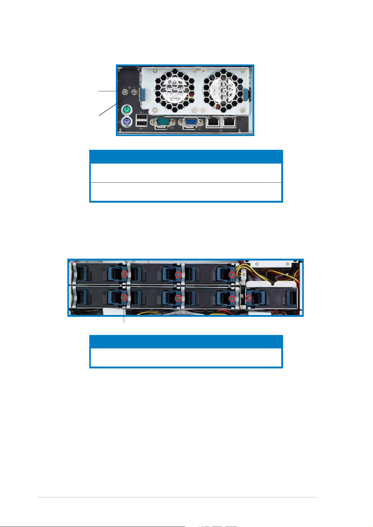
Page 18
1.6.21.6.2
1.6.2
1.6.21.6.2
LED1 forLED1 for
LED1 for
LED1 forLED1 for
Rear Fan 1Rear Fan 1
Rear Fan 1
Rear Fan 1Rear Fan 1
LED2 forLED2 for
LED2 for
LED2 forLED2 for
Rear Fan 2Rear Fan 2
Rear Fan 2
Rear Fan 2Rear Fan 2
Rear fan LEDsRear fan LEDs
Rear fan LEDs
Rear fan LEDsRear fan LEDs
1.6.31.6.3
1.6.3
1.6.31.6.3
LEDLED
LED
LEDLED
LED1 Green Rear Fan 1 is in normal operation
LED2 Green Rear Fan 2 is in normal operation
System fan LEDSystem fan LED
System fan LED
System fan LEDSystem fan LED
Color Color
Color
Color Color
Orange Rear Fan 1 is faulty
Orange Rear Fan 2 is faulty
DescriptionDescription
Description
DescriptionDescription
Each system fan has an LED to indicate the fan status.
LEDLED
LED
LEDLED
1-81-8
1-8
1-81-8
LEDLED
LED
LEDLED
LED Green Fan is in normal operation
ColorColor
Color
ColorColor
Orange Fan is faulty
DescriptionDescription
Description
DescriptionDescription
Chapter 1: Product introductionChapter 1: Product introduction
Chapter 1: Product introduction
Chapter 1: Product introductionChapter 1: Product introduction
Page 19
1.6.41.6.4
1.6.4
1.6.41.6.4
Power supply LEDPower supply LED
Power supply LED
Power supply LEDPower supply LED
Each system fan has an LED to indicate the fan status.
LEDLED
LED
LEDLED
LEDLED
LED
LEDLED
LED Green Blinking Power off and in standby mode
1.6.51.6.5
1.6.5
1.6.51.6.5
ColorColor
Color
ColorColor
Green On The power supply module is in normal operation
Orange On One of the two power modules is disconnected
Off Off Both power supply modules are disconnected
LAN port LEDsLAN port LEDs
LAN port LEDs
LAN port LEDsLAN port LEDs
Display statusDisplay status
Display status
Display statusDisplay status
DescriptionDescription
Description
DescriptionDescription
from the power outlet or is defective
from the power outlet or are defective
SPEED LEDSPEED LED
SPEED LED
SPEED LEDSPEED LED
ACT/LINK LEDACT/LINK LED
ACT/LINK LED
ACT/LINK LEDACT/LINK LED
ACT/LINK LEDACT/LINK LED
ACT/LINK LED
ACT/LINK LEDACT/LINK LED
StatusStatus
Status
StatusStatus
OFF No link OFF 10 Mbps connection
GREEN Linked ORANGE 100 Mbps connection
BLINKING Data activity GREEN 1 Gbps connection
ASUS AP2400R-E2ASUS AP2400R-E2
ASUS AP2400R-E2
ASUS AP2400R-E2ASUS AP2400R-E2
DescriptionDescription
Description
DescriptionDescription
StatusStatus
Status
StatusStatus
SPEED LEDSPEED LED
SPEED LED
SPEED LEDSPEED LED
DescriptionDescription
Description
DescriptionDescription
1-91-9
1-9
1-91-9
Page 20

1-101-10
1-10
1-101-10
Chapter 1: Product introductionChapter 1: Product introduction
Chapter 1: Product introduction
Chapter 1: Product introductionChapter 1: Product introduction
Page 21
Chapter 2
This chapter lists the hardware
setup procedures that you have to
perform when installing or removing
system components.
ASUS AP2400R-E2ASUS AP2400R-E2
ASUS AP2400R-E2
ASUS AP2400R-E2ASUS AP2400R-E2
Hardware setup
1-1
Page 22
2.1 Chassis cover
The chassis features a “screwless design” that allows convenient assembly
and disassembly.
• Remove the front bezel to access the hot-swap HDDs, optical drive,
and floppy drive.
• Remove the chassis cover to access the internal components or if you
want to install system devices.
2.1.12.1.1
2.1.1
2.1.12.1.1
To remove the front bezel:
1. Hold the sides of the front bezel,
then slightly press the middle
part to disengage it from the
front panel.
2. Pull the bezel from the front
panel.
Removing the front bezelRemoving the front bezel
Removing the front bezel
Removing the front bezelRemoving the front bezel
Press here to releasePress here to release
Press here to release
Press here to releasePress here to release
2-22-2
2-2
2-22-2
Chapter 2: Hardware setupChapter 2: Hardware setup
Chapter 2: Hardware setup
Chapter 2: Hardware setupChapter 2: Hardware setup
Page 23
2.1.22.1.2
2.1.2
2.1.22.1.2
Front halfFront half
Front half
Front halfFront half
Removing the top coverRemoving the top cover
Removing the top cover
Removing the top coverRemoving the top cover
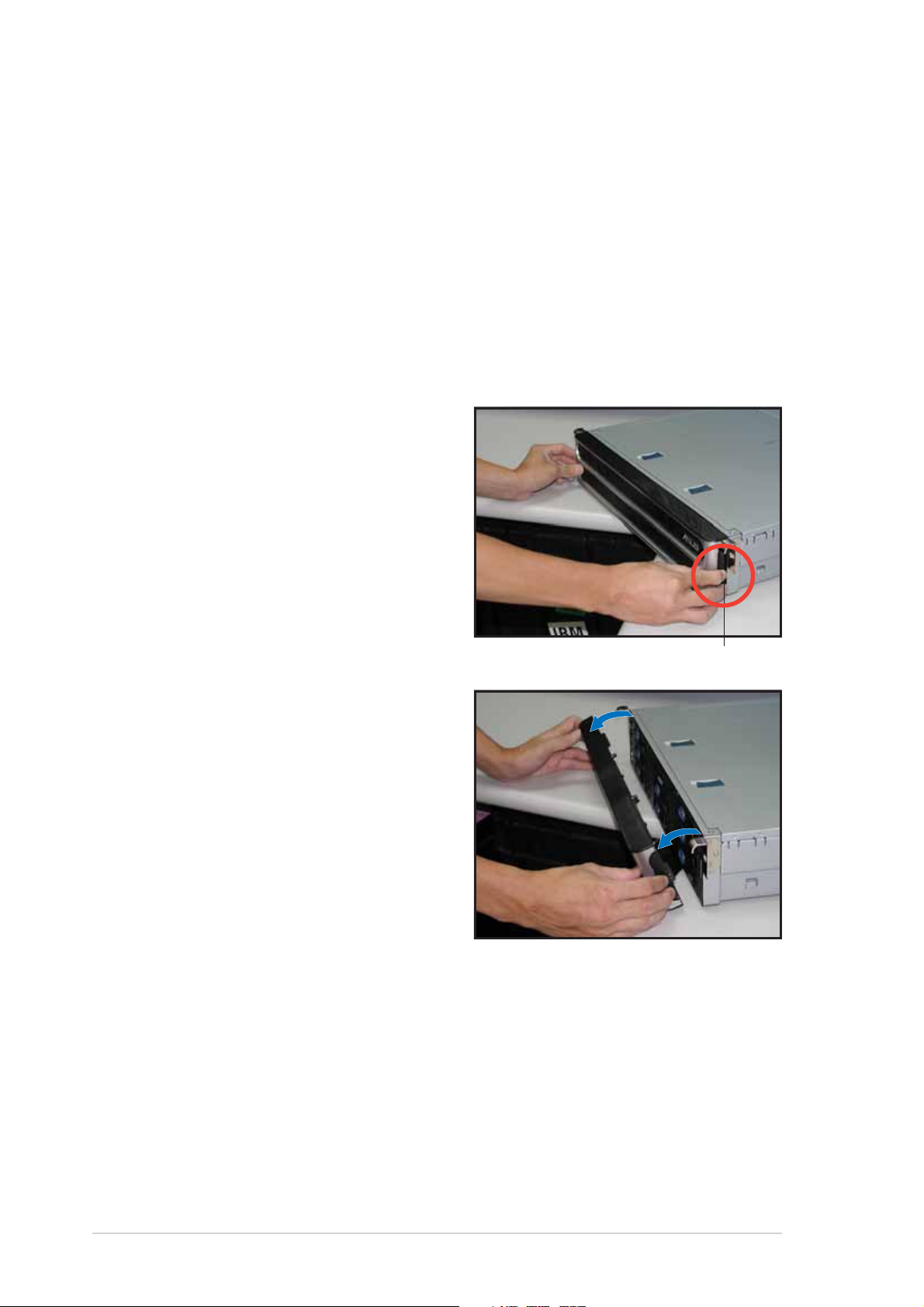
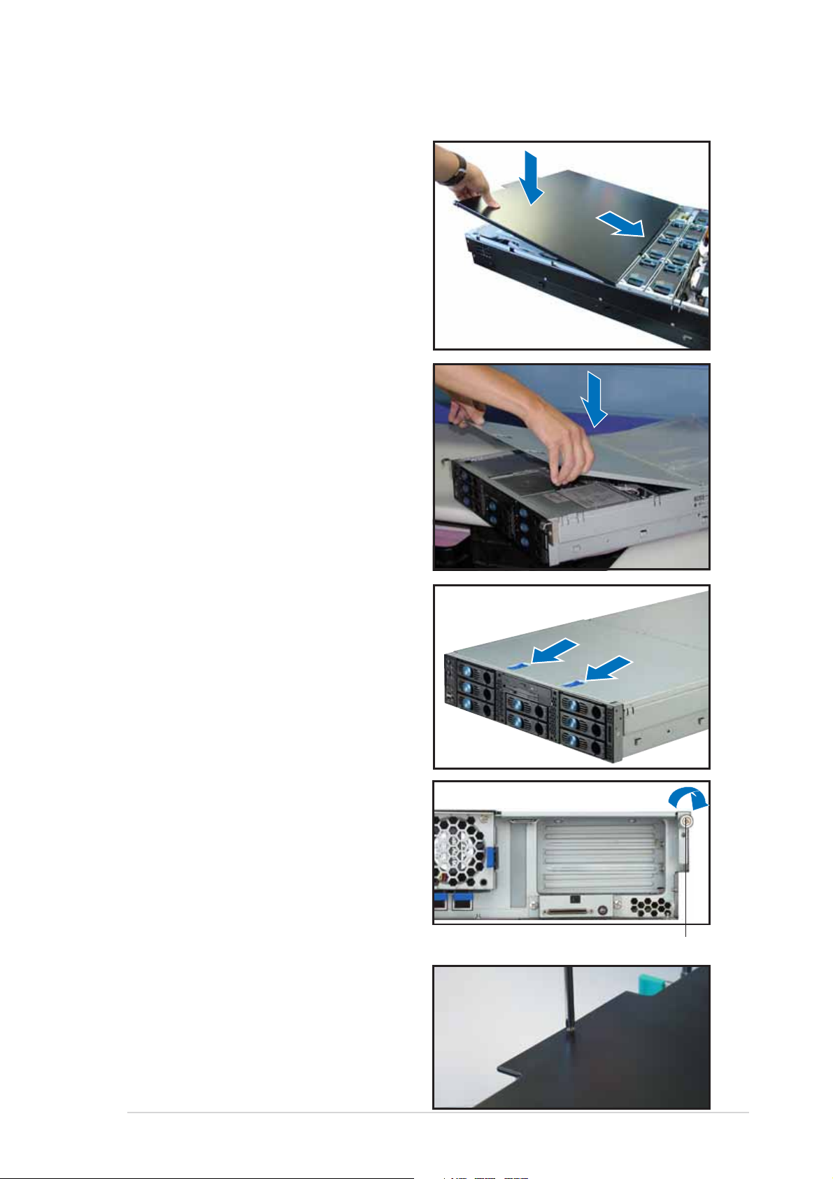
To remove the front half of the top cover:
1. Push the two sliding locks on the
top cover to release.
2. With both hands, flip up the
front corners of the top cover,
then lift.
The front corners of the cover
have dents that match those on
the chassis. These dents provide
a holding mechanism and keeps
the cover in place even when the
sliding locks are released.
If you wish to access the hot-swappable system fans, backplanes, optical
drive, and floppy drive, you only need to remove the front half of the
top cover.
ASUS AP2400R-E2ASUS AP2400R-E2
ASUS AP2400R-E2
ASUS AP2400R-E2ASUS AP2400R-E2
MatchingMatching
Matching
MatchingMatching
dentsdents
dents
dentsdents
2-32-3
2-3
2-32-3
Page 24
Rear halfRear half
Rear half
Rear halfRear half
You need to remove the front half of the top cover before you can
remove the rear half of the top cover. Refer to section “2.1.1 Removing
the top cover (front half)” for instructions.
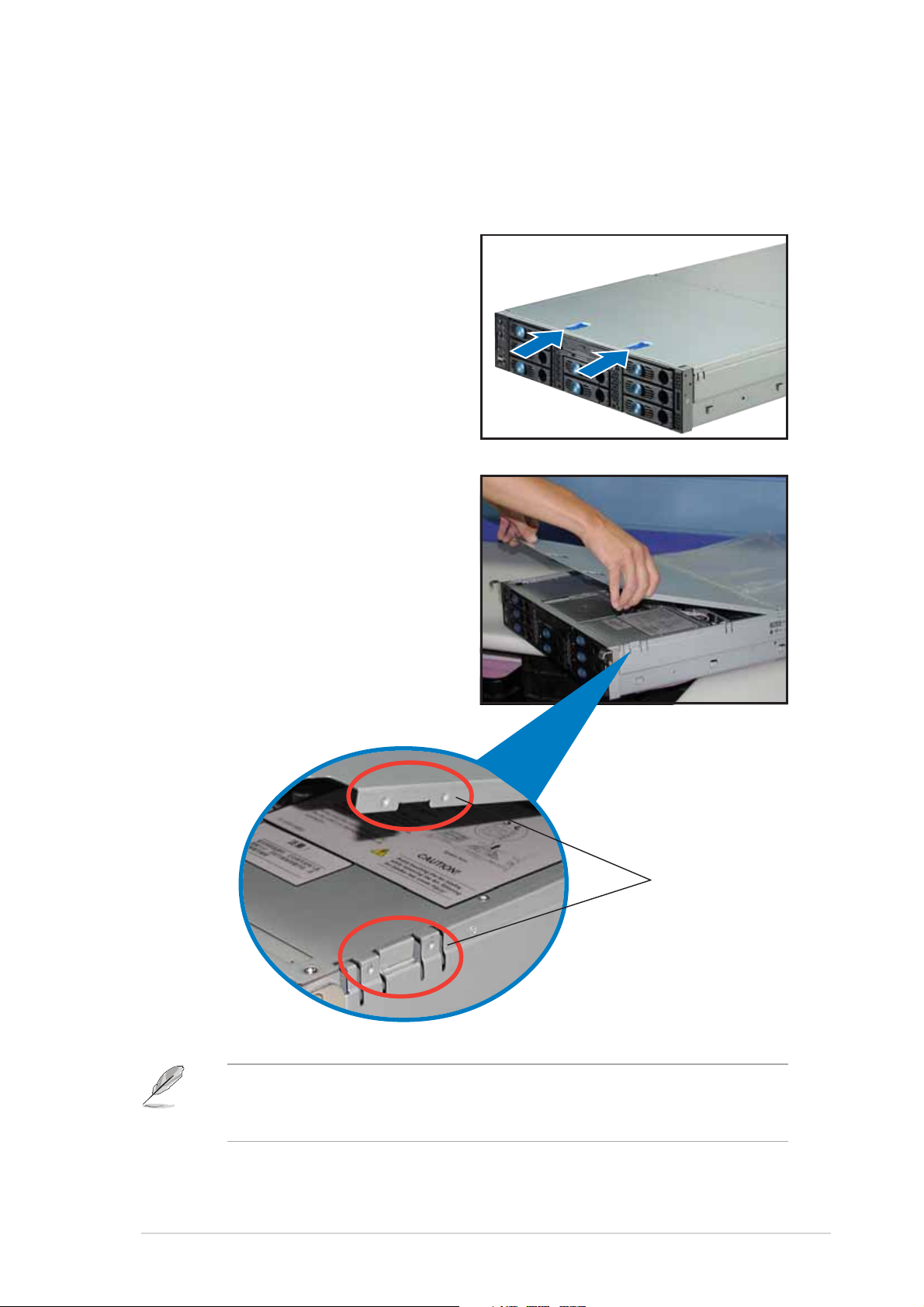
To remove the rear half of the top cover:
1. Loosen the thumbscrew that
secures the top cover on the
rear part of the chassis.
2. Remove the screw on the rear
half of the cover.
ThumbscrewThumbscrew
Thumbscrew
ThumbscrewThumbscrew
3. Firmly hold the rear half of the
top cover, then remove it from
the chassis.
The barebone server without the
top cover is shown on the right.
2-42-4
2-4
2-42-4
Chapter 2: Hardware setupChapter 2: Hardware setup
Chapter 2: Hardware setup
Chapter 2: Hardware setupChapter 2: Hardware setup
Page 25
2.1.32.1.3
2.1.3
2.1.32.1.3
Installing the top coverInstalling the top cover
Installing the top cover
Installing the top coverInstalling the top cover
To install the top cover:
1. Place the rear half of the top
cover over the chassis as shown,
and align the mid-hooks with the
notches on the sides.
2. Slide the cover toward the front
panel until the mid-hooks are
locked into the notches.
3. Flip down the front half part of
the top cover.
4. Push the sliding locks toward the
front edge to secure the front
half of the top cover in place.
5. Tighten the thumbscrew on the
rear corner of the cover to
completely secure the top cover.
6. Replace the screw on the rear
half of the cover.
ThumbscrewThumbscrew
Thumbscrew
ThumbscrewThumbscrew
ASUS AP2400R-E2ASUS AP2400R-E2
ASUS AP2400R-E2
ASUS AP2400R-E2ASUS AP2400R-E2
2-52-5
2-5
2-52-5
Page 26
2.1.42.1.4
2.1.4
2.1.42.1.4
Removing the air ductRemoving the air duct
Removing the air duct
Removing the air ductRemoving the air duct
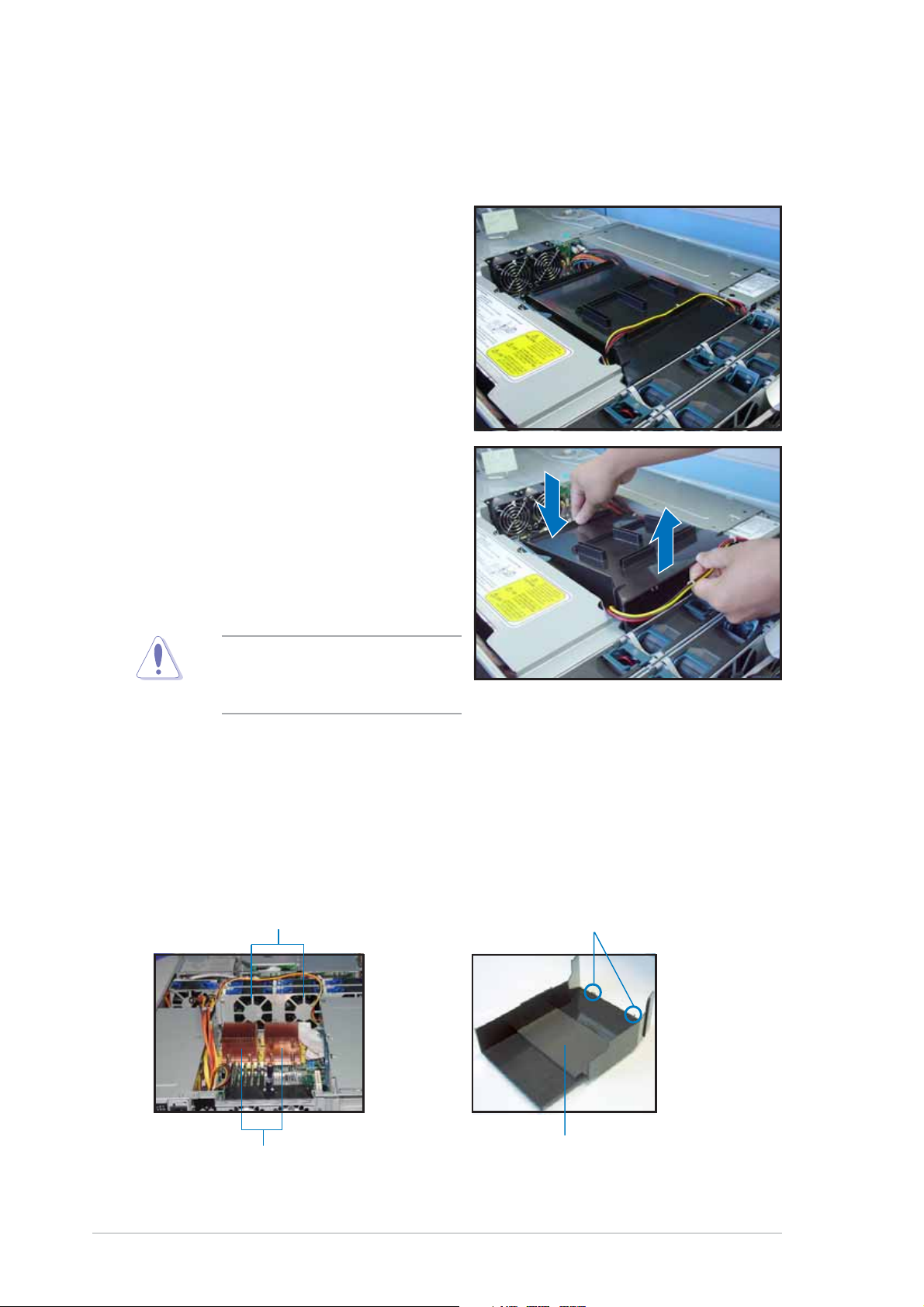
To remove the air duct:
1. Carefully route the cables that
may interfere when removing the
air duct.
2. Hold the rear part of the air duct
and press it for about a fraction
of an inch, just enough to tilt the
front end.
3. When tilted, carefully pull the air
duct upward to release it from
the chassis.
Be careful not to pull off or
break any cables while
removing the air duct.
2.1.52.1.5
2.1.5
2.1.52.1.5
Installing the air ductInstalling the air duct
Installing the air duct
Installing the air ductInstalling the air duct
To install the air duct:
1. Take note of the parts of the air duct that should match specific
locations inside the chassis.
Metal strips to fit theMetal strips to fit the
Metal strips to fit the
Metal strips to fit theMetal strips to fit the
plastic clips on the air ductplastic clips on the air duct
plastic clips on the air duct
plastic clips on the air ductplastic clips on the air duct
Plastic clips to grip thePlastic clips to grip the
Plastic clips to grip the
Plastic clips to grip thePlastic clips to grip the
metal strips on the fan cagemetal strips on the fan cage
metal strips on the fan cage
metal strips on the fan cagemetal strips on the fan cage
2-62-6
2-6
2-62-6
CPU heatsinksCPU heatsinks
CPU heatsinks
CPU heatsinksCPU heatsinks
Flat rubber pad should matchFlat rubber pad should match
Flat rubber pad should match
Flat rubber pad should matchFlat rubber pad should match
the top of the two heatsinksthe top of the two heatsinks
the top of the two heatsinks
the top of the two heatsinksthe top of the two heatsinks
Chapter 2: Hardware setupChapter 2: Hardware setup
Chapter 2: Hardware setup
Chapter 2: Hardware setupChapter 2: Hardware setup
Page 27
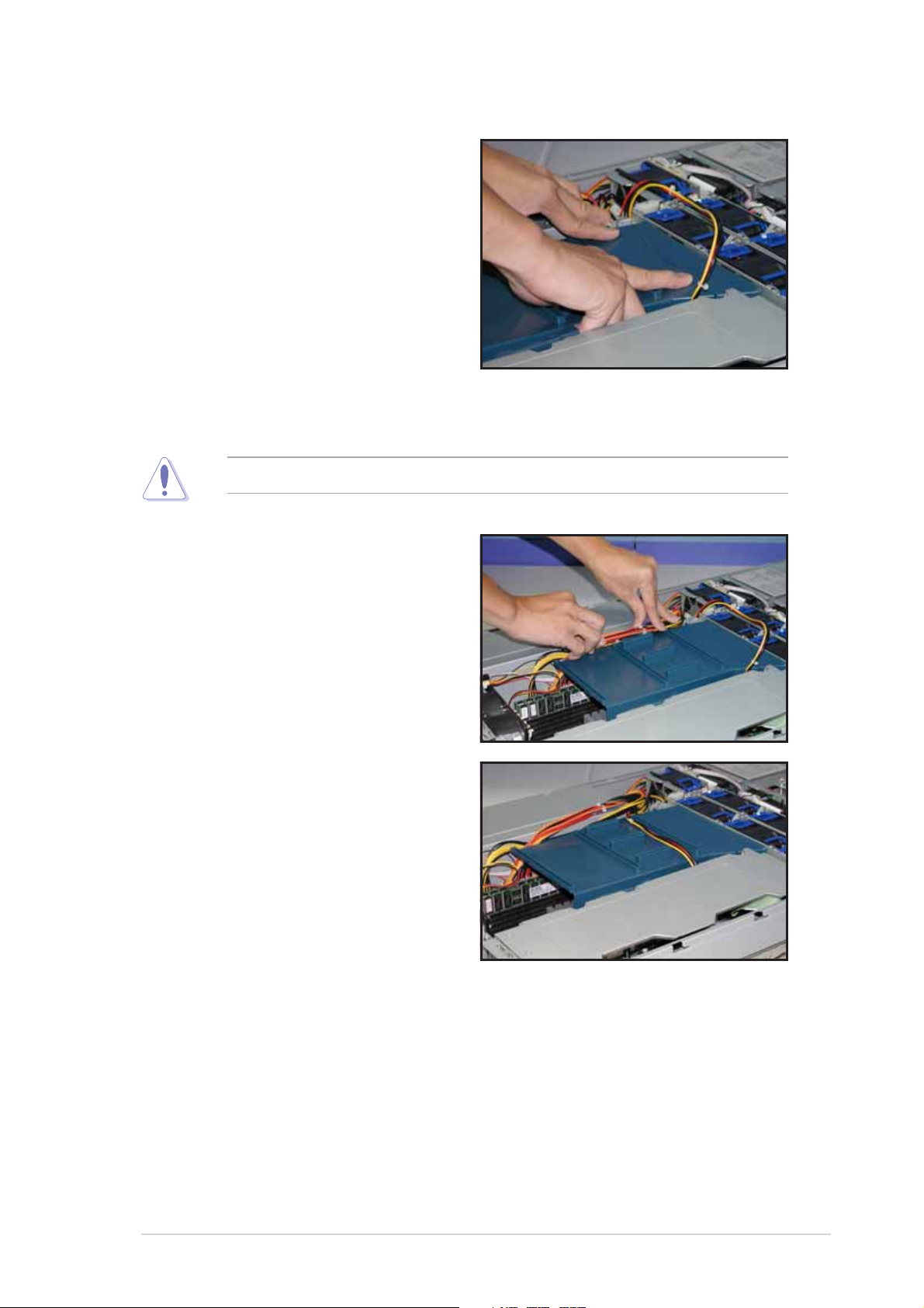
2. Position the air duct inside the
chassis with the plastic clips
matching the two vertical metal
strips on the fan cage.
3. Check the rubber pads
underneath the air duct and
ensure that they are in place;
otherwise, the air duct will not
fit properly.
4. Fit the other end of the air duct
making sure that no power cable
is strayed under it.
Be careful not to pull off or break any cables while installing the air duct.
5. When the air duct is in place,
arrange the power cable cluster
to fit the space beside the air
duct.
6. Flatten the power cable that
runs across the air duct. When
properly installed, the air duct
should appear as shown.
ASUS AP2400R-E2ASUS AP2400R-E2
ASUS AP2400R-E2
ASUS AP2400R-E2ASUS AP2400R-E2
2-72-7
2-7
2-72-7
Page 28
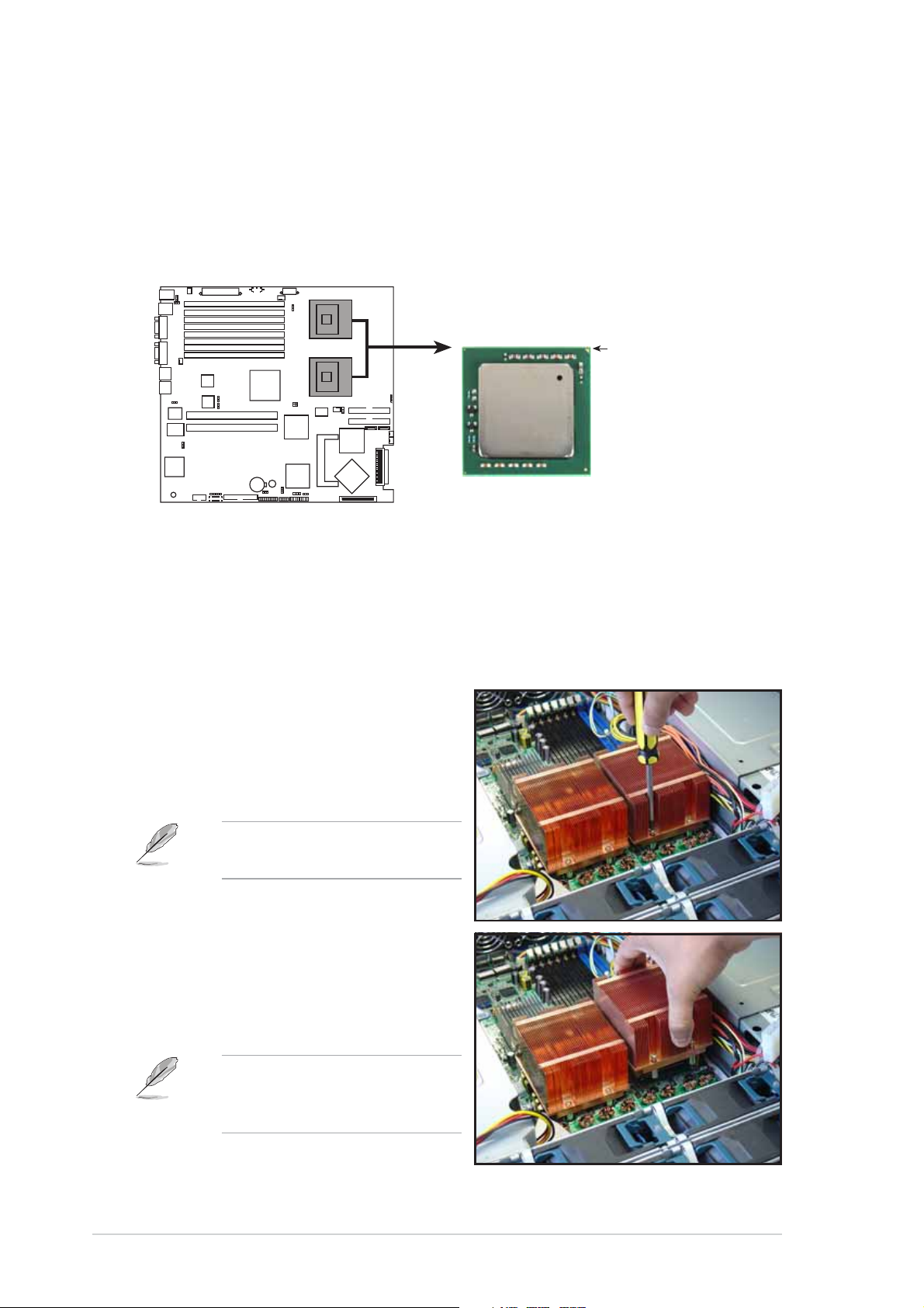
2.2 Central Processing Unit (CPU)
The motherboard comes with two surface mount 604-pin Zero Insertion
Force (ZIF) socket and designed for the Intel
Note in the illustration that the CPU has a gold triangular mark on one
corner. This mark indicates the processor Pin 1 that should match a
specific corner of the CPU socket.
®
Xeon™ processors.
NCL-DS1R2 CPU Socket 604
2.2.12.2.1
2.2.1
2.2.12.2.1
Removing the CPU heatsinkRemoving the CPU heatsink
Removing the CPU heatsink
Removing the CPU heatsinkRemoving the CPU heatsink
Intel Xeon
®
NCL-DS1R2
Gold Arrow
Pin A1
You must remove the CPU heatsink(s) before installing the CPU(s).
To remove the CPU heatsink:
1. Use a Phillips (cross) screwdriver
to loosen the four screws that
secure the heatsink until it is
released.
You don’t need to detach the
screws from the heatsink.
2. Carefully lift the heatsink from
the motherboard.
3. Remove the rubber pad(s) on
top of the CPU socket(s).
Remove the rubber pad(s)
only when you are ready to
install the CPU(s).
2-82-8
2-8
2-82-8
Chapter 2: Hardware setupChapter 2: Hardware setup
Chapter 2: Hardware setup
Chapter 2: Hardware setupChapter 2: Hardware setup
Page 29
4. Remove the rubber pad(s) on
top of the CPU socket(s).
Remove the rubber pad(s)
only when you are ready to
install the CPU(s).
2.2.22.2.2
2.2.2
2.2.22.2.2
(inner socket with rubber pad)(inner socket with rubber pad)
(inner socket with rubber pad)
(inner socket with rubber pad)(inner socket with rubber pad)
Installing a CPUInstalling a CPU
Installing a CPU
Installing a CPUInstalling a CPU
• The motherboard supports either one or two CPUs. If you are
installing only one CPU, you MUST install it in CPU socket 1.
• If you are installing two CPUs, install in the CPU socket 2 first.
CPU Socket 1CPU Socket 1
CPU Socket 1
CPU Socket 1CPU Socket 1
(outer socket)(outer socket)
(outer socket)
(outer socket)(outer socket)
CPU Socket 2CPU Socket 2
CPU Socket 2
CPU Socket 2CPU Socket 2
Incorrect installation of the CPU into the socket may bend the pins and
severely damage the CPU!
To install the CPUs:
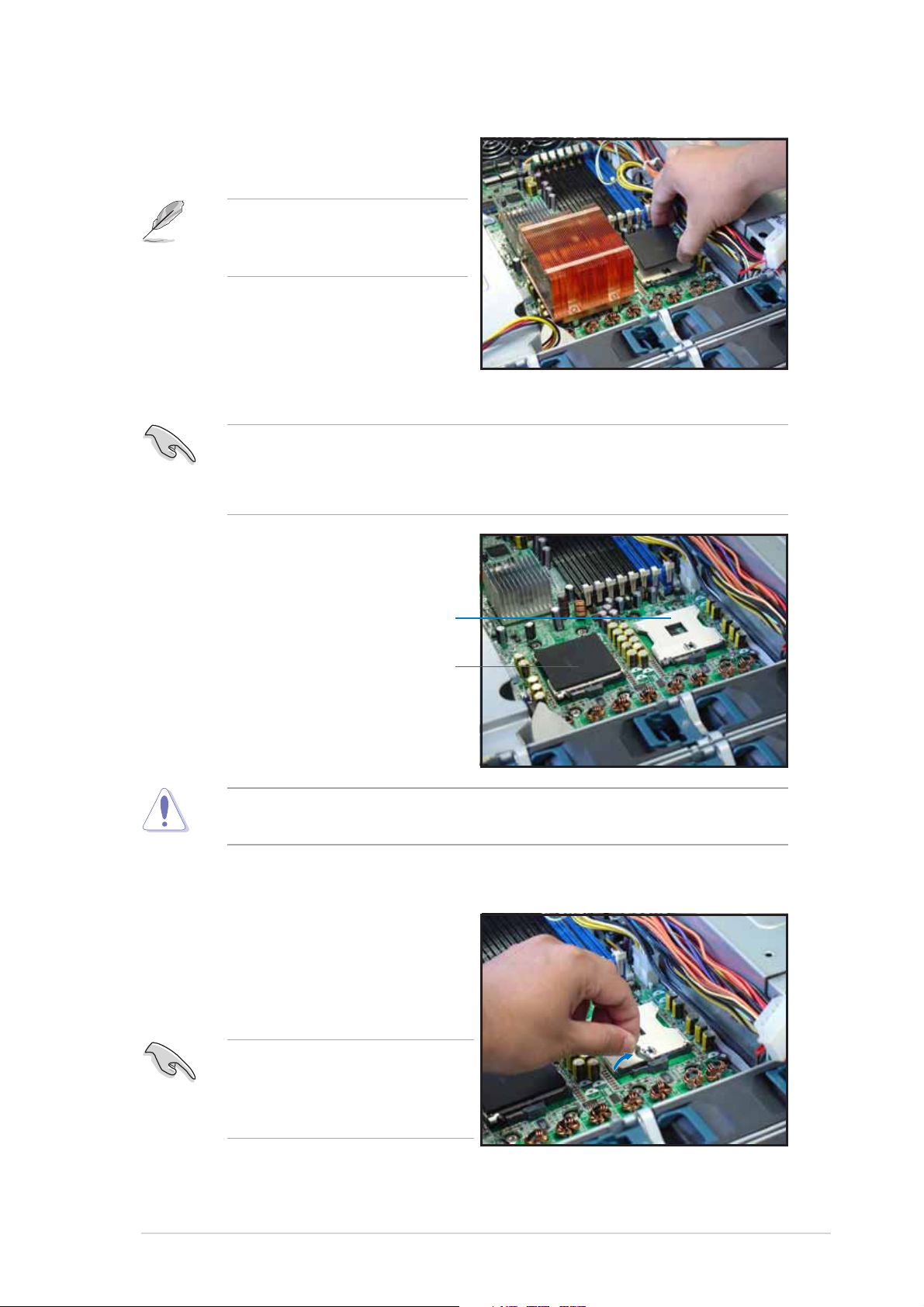
1. Locate the CPU1 socket on the
motherboard. Flip up the socket
lever and push it all the way to
the other side.
Make sure that the socket
lever is pushed back all the
way. Otherwise the CPU does
not fit in completely.
ASUS AP2400R-E2ASUS AP2400R-E2
ASUS AP2400R-E2
ASUS AP2400R-E2ASUS AP2400R-E2
2-92-9
2-9
2-92-9
Page 30
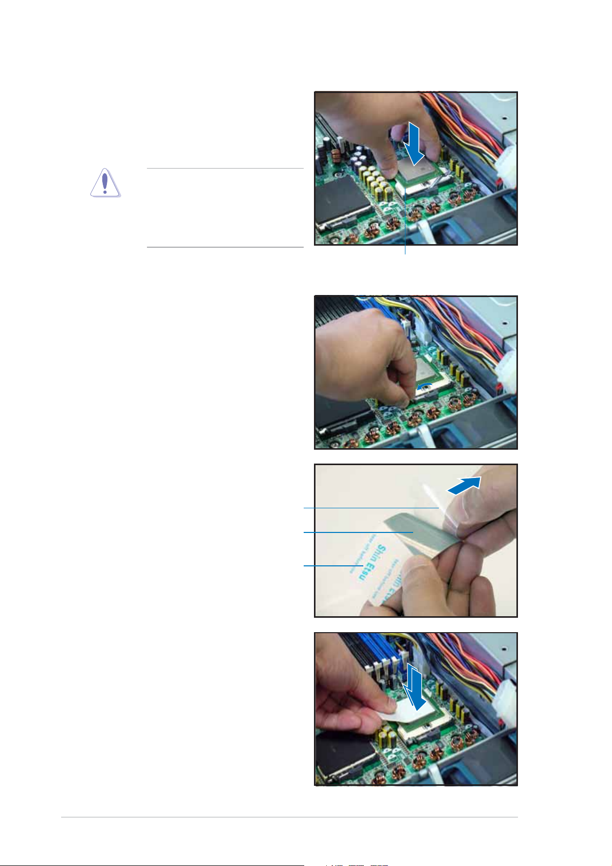
2. Position the CPU above the
socket as shown.
3. Carefully insert the CPU into the
socket until it fits in place.
The CPU fits only in one
correct orientation. DO NOT
force the CPU into the socket
to prevent bending the pins
and damaging the CPU!
4. Carefully push down the socket
lever to secure the CPU. The
lever clicks on the side tab to
indicate that it is locked.
Marked cornerMarked corner
Marked corner
Marked cornerMarked corner
5. Peel off the plastic film of the
thermal grease strip.
Plastic filmPlastic film
Plastic film
Plastic filmPlastic film
Thermal greaseThermal grease
Thermal grease
Thermal greaseThermal grease
Thermal grease stripThermal grease strip
Thermal grease strip
Thermal grease stripThermal grease strip
6. Place the thermal grease strip
on top of the installed CPU.
Make sure that the thermal
grease covers the entire surface
of the CPU.
2-102-10
2-10
2-102-10
Chapter 2: Hardware setupChapter 2: Hardware setup
Chapter 2: Hardware setup
Chapter 2: Hardware setupChapter 2: Hardware setup
Page 31

7. Press the thermal grease strip
evenly against the surface of the
CPU.
8. Peel off the thermal grease strip.
Make sure that the grease
remains on top of the CPU.
9. Repeat steps 2 to 8 if you wish
to install a second CPU.
ASUS AP2400R-E2ASUS AP2400R-E2
ASUS AP2400R-E2
ASUS AP2400R-E2ASUS AP2400R-E2
2-112-11
2-11
2-112-11
Page 32

2.2.32.2.3
2.2.3
2.2.32.2.3
To install the CPU heatsink:
1. Carefully place the heatsink on
top of the installed CPU (CPU1).
2. Hold down the heatsink lightly
and twist each of the four
screws with a Philips (cross)
screwdriver just enough to
attach the heatsink to the
motherboard. When the four
screws are attached, tighten
them one by one to completely
secure the heatsink.
Installing the CPU heatsinkInstalling the CPU heatsink
Installing the CPU heatsink
Installing the CPU heatsinkInstalling the CPU heatsink
3. If you installed a second CPU,
follow steps 1 and 2 to install
the second CPU heatsink.
2-122-12
2-12
2-122-12
Chapter 2: Hardware setupChapter 2: Hardware setup
Chapter 2: Hardware setup
Chapter 2: Hardware setupChapter 2: Hardware setup
Page 33

2.3 System memory
The motherboard comes with eight Double Data Rate (DDR) Dual Inline
Memory Module (DIMM) sockets. These sockets support up to 16GB system
memory using 2.5V 184-pin registered ECC PC2700 DDR DIMMs.
80 Pins104 Pins
DIMM_B4
®
NCL-DS1R2
NCL-DS1R2 184-pin DDR DIMM sockets
DIMM_A4
DIMM_B3
DIMM_A3
DIMM_B2
DIMM_A2
DIMM_B1
DIMM_A1
2.3.12.3.1
2.3.1
2.3.12.3.1
Memory configurationsMemory configurations
Memory configurations
Memory configurationsMemory configurations
You may install 256 MB, 512 MB, 1 GB, and 2 GB registered ECC DDR
DIMMs into the DIMM sockets.
• Always install DIMMs with the same CAS latency. For optimum
compatibility, it is recommended that you obtain memory modules
from the same vendor. Refer to the DDR Qualified Vendors List at
the ASUS web site.
• Due to chipset resource allocation, the system may detect less than 16 GB
system memory when you installed eight 2 GB DDR memory modules.
• This motherboard does not support memory modules made up of
128 Mb chips or 256 MB double-rank x16 memory modules.
• Do not install double-rank and single-rank memory modules at the
same time.
• The server motherboard does not support installation of three or
five memory modules.
• If you are installing only one memory module, install into the blue socket
labeled DIMM_B4. Installing into any other socket would not work.
ModeMode
Mode
ModeMode
Single-channel*
Dual-channel
Dual-channel
Dual-channel
Dual-channel
DIMM_B4DIMM_B4
DIMM_B4
DIMM_B4DIMM_B4
DIMM_A4DIMM_A4
DIMM_A4
DIMM_A4DIMM_A4
DIMM_B3DIMM_B3
DIMM_B3
DIMM_B3DIMM_B3
DIMM_A3DIMM_A3
DIMM_A3
DIMM_A3DIMM_A3
DIMM_B2DIMM_B2
DIMM_B2
DIMM_B2DIMM_B2
DIMM_A2DIMM_A2
DIMM_A2
DIMM_A2DIMM_A2
DIMM_B1DIMM_B1
DIMM_B1
DIMM_B1DIMM_B1
DIMM_A1DIMM_A1
DIMM_A1
DIMM_A1DIMM_A1
Populated with DIMM
* Install only one memory module for single-channel memory configuration.
ASUS AP2400R-E2ASUS AP2400R-E2
ASUS AP2400R-E2
ASUS AP2400R-E2ASUS AP2400R-E2
2-132-13
2-13
2-132-13
Page 34

2.3.22.3.2
2.3.2
2.3.22.3.2
Installing a DIMMInstalling a DIMM
Installing a DIMM
Installing a DIMMInstalling a DIMM
Make sure to unplug the power supply before adding or removing DIMMs
or other system components. Failure to do so may cause severe damage
to both the motherboard and the components.
Follow these steps to install a DIMM.
1. Unlock a DIMM socket by pressing
the retaining clips outward.
2. Align a DIMM on the socket such
that the notch on the DIMM
matches the break on the socket.
Unlocked retaining clipUnlocked retaining clip
Unlocked retaining clip
Unlocked retaining clipUnlocked retaining clip
3. Firmly insert the DIMM into the
socket until the retaining clips
snap back in place and the DIMM
is properly seated.
Locked retaining clipLocked retaining clip
Locked retaining clip
Locked retaining clipLocked retaining clip
2.3.32.3.3
2.3.3
2.3.32.3.3
Removing a DIMMRemoving a DIMM
Removing a DIMM
Removing a DIMMRemoving a DIMM
Follow these steps to remove a DIMM.
1. Simultaneously press the
retaining clips outward to unlock
the DIMM.
2. Remove the DIMM from the
socket.
Support the DIMM lightly with
your fingers when pressing
the retaining clips. The DIMM
might get damaged when it
flips out with extra force.
2-142-14
2-14
2-142-14
Chapter 2: Hardware setupChapter 2: Hardware setup
Chapter 2: Hardware setup
Chapter 2: Hardware setupChapter 2: Hardware setup
Page 35
2.4 Hard disk drives
To install a hard disk drive:
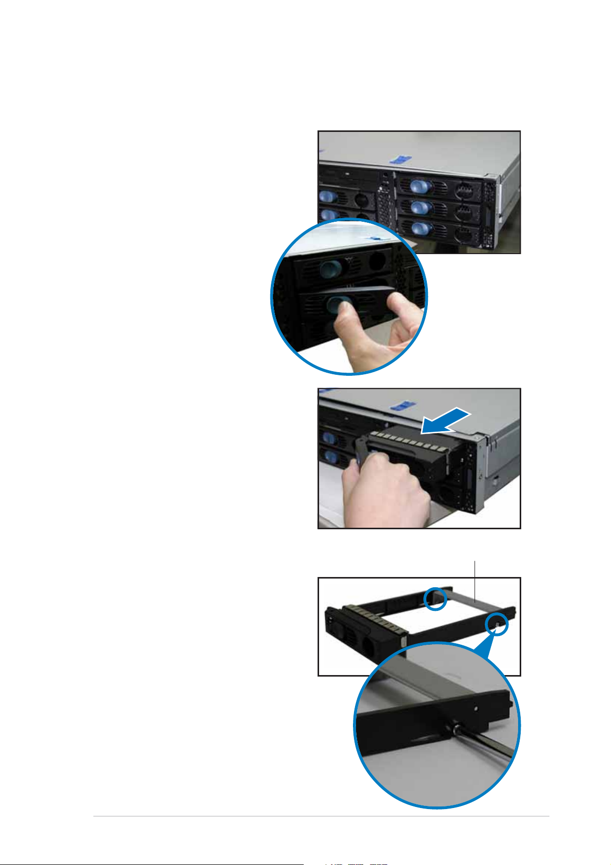
1. Open the front bezel to access
the hot-swap drive trays.
2. Release a drive tray by pushing
the spring lock to the right, then
pulling the tray lever outward.
The drive tray ejects slightly
after you pull out the lever.
3. Firmly hold the tray lever and
pull the drive tray out of the
bay.
4. An empty drive tray includes a
metal bracket for support. Use a
Phillips (cross) screwdriver to
remove the bracket if you wish
to install a hard disk in the drive
tray.
Metal bracket
ASUS AP2400R-E2ASUS AP2400R-E2
ASUS AP2400R-E2
ASUS AP2400R-E2ASUS AP2400R-E2
2-152-15
2-15
2-152-15
Page 36

5. Place a hard disk drive into the
drive tray, and secure it with
four screws (two on each side).
6. Carefully insert drive tray and
push it all the way to the depth
of the bay until just a small
fraction of the tray edge
protrudes.
7. Push the tray lever until it clicks,
and secures the drive tray in
place. The drive tray is correctly
placed when its front edge aligns
with the bay edge.
2-162-16
2-16
2-162-16
Chapter 2: Hardware setupChapter 2: Hardware setup
Chapter 2: Hardware setup
Chapter 2: Hardware setupChapter 2: Hardware setup
Page 37

2.5 Expansion cards
The system motherboard comes with two PCI-X expansion slots, one slot is
installed with the PCI cage to support three full-length expansion cards. A
ZCR slot is also available for installation of a Zero Channel RAID card.
PCI-X1PCI-X1
PCI-X1
PCI-X1PCI-X1
PCI-X slots inside the PCI cagePCI-X slots inside the PCI cage
PCI-X slots inside the PCI cage
PCI-X slots inside the PCI cagePCI-X slots inside the PCI cage
2.5.12.5.1
2.5.1
2.5.12.5.1
Installing a low-profile expansion cardInstalling a low-profile expansion card
Installing a low-profile expansion card
Installing a low-profile expansion cardInstalling a low-profile expansion card
PCI-X2PCI-X2
PCI-X2
PCI-X2PCI-X2
To install a low-profile expansion card:
1. Firmly hold the card by the
edges and align the card
connector to the PCI-X slot.
2. Push the card connector into the
slot until it fits in place.
3. Secure the card bracket with a
screw.
ASUS AP2400R-E2ASUS AP2400R-E2
ASUS AP2400R-E2
ASUS AP2400R-E2ASUS AP2400R-E2
Card screwCard screw
Card screw
Card screwCard screw
2-172-17
2-17
2-172-17
Page 38
2.5.22.5.2
2.5.2
2.5.22.5.2
Installing a full-length expansion cardInstalling a full-length expansion card
Installing a full-length expansion card
Installing a full-length expansion cardInstalling a full-length expansion card
The full-length expansion cards are inside the PCI cage. If you wish to
install full-length expansion cards, you need to remove the PCI cage from
the chassis.
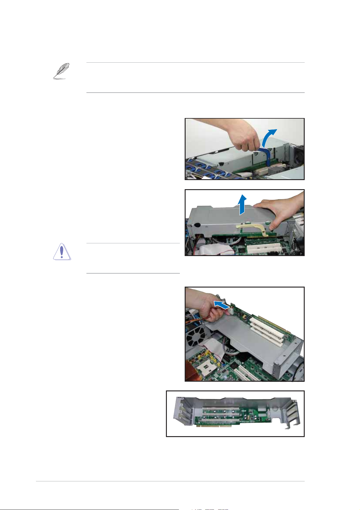
To install a full-length expansion card:
1. Disengage the PCI cage from the
chassis by lifting the cage handle
o
to about 45
angle.
2. Firmly hold and lift the cage as
shown to completely detach it
from the chassis, then turn it
over to access the power
connector.
DO NOT lift the PCI cage too
high to avoid pulling and
breaking the power cable!
3. Disconnect the 4-pin power plug
from the connector inside the
cage.
4. Place the cage on a flat
stable surface with the slot
facing up, and prepare the
card that you want to
install.
2-182-18
2-18
2-182-18
Internal view of PCI cageInternal view of PCI cage
Internal view of PCI cage
Internal view of PCI cageInternal view of PCI cage
Chapter 2: Hardware setupChapter 2: Hardware setup
Chapter 2: Hardware setup
Chapter 2: Hardware setupChapter 2: Hardware setup
Page 39

Important notes on installing PCI cards in the PCI cageImportant notes on installing PCI cards in the PCI cage
Important notes on installing PCI cards in the PCI cage
Important notes on installing PCI cards in the PCI cageImportant notes on installing PCI cards in the PCI cage
• Install PCI-X cards in the following order:
First PCI-X card – top slot (furthest from motherboard)
Second PCI-X card – middle slot
Third PCI-X card – bottom slot (nearest the motherboard)
Exceptions:
1. Install a
cables.
2. Install a LAN card to the bottom slot for easy connection of LAN
(RJ-45) cables from the chassis rear panel.
• The PCI-X frequency depends on the number of cards installed on
the PCI cage. Refer to the table below for details.
Installed PCI-X cardsInstalled PCI-X cards
Installed PCI-X cards
Installed PCI-X cardsInstalled PCI-X cards
One 133 MHz
Two 100 MHz
Dual-channel 66 MHz
RAID card to the top slot to facilitate connection of SCSI
5. Remove the metal cover
opposite the PCI-X slot that you
want to use, then install a PCI-X
card as shown. The card golden
connectors should match the
notches on the slot.
PCI FrequencyPCI Frequency
PCI Frequency
PCI FrequencyPCI Frequency
6. Firmly push down the card until
it is completely seated on the
slot.
7. Secure the card bracket with a
screw.
8. Connect power or signal cable(s)
to the card, if applicable.
Repeat steps 5 to 8 if you wish to install other PCI-X cards.
ASUS AP2400R-E2ASUS AP2400R-E2
ASUS AP2400R-E2
ASUS AP2400R-E2ASUS AP2400R-E2
2-192-19
2-19
2-192-19
Page 40

9. Re-connect the 4-pin power plug
to the connector inside the
cage.
When re-connecting the power
plug, place the PCI cage close
enough to avoid pulling the
power cable.
10. Before re-installing the PCI cage
into the chassis, check that all
cables on the PCI cage bay are
properly connected and routed.
Cables on the PCI cage bayCables on the PCI cage bay
Cables on the PCI cage bay
Cables on the PCI cage bayCables on the PCI cage bay
11. Take note of the two pegs on
the PCI cage bay. These pegs
should match the holes on the
cage to make sure it fits in
place.
PCI cage pegsPCI cage pegs
PCI cage pegs
PCI cage pegsPCI cage pegs
2-202-20
2-20
2-202-20
Chapter 2: Hardware setupChapter 2: Hardware setup
Chapter 2: Hardware setup
Chapter 2: Hardware setupChapter 2: Hardware setup
Page 41

12. Position the PCI cage into the
bay making sure that the pegs
go into the holes on the front of
the cage, and the dents on the
rear part match those on the
chassis.
13. Match and push the cage card
connector into the PCI-X slot
(PCI-X2) until the PCI cage fits in
place.
14. Ensure that the PCI cage card
golden connectors completely fit
the slot.
If properly installed, the top of
the PCI cage aligns with the top
edge of the rear panel.
2.5.32.5.3
2.5.3
2.5.32.5.3
The ZCR socket on the motherboard
supports the Adaptec AIC-2015
Zero-Channel RAID card that allows
RAID 0, RAID 1, RAID 10, RAID 5,
RAID 50, and JBOD configurations.
ZCR socketZCR socket
ZCR socket
ZCR socketZCR socket
ASUS AP2400R-E2ASUS AP2400R-E2
ASUS AP2400R-E2
ASUS AP2400R-E2ASUS AP2400R-E2
2-212-21
2-21
2-212-21
Page 42

2.5.42.5.4
2.5.4
2.5.42.5.4
Configuring an expansion cardConfiguring an expansion card
Configuring an expansion card
Configuring an expansion cardConfiguring an expansion card
After installing the expansion card, configure the it by adjusting the
software settings.
1. Turn on the system and change the necessary BIOS settings, if any.
See Chapter 5 for information on BIOS setup.
2. Assign an IRQ to the card. Refer to the following tables.
3. Install the software drivers for the expansion card.
Standard interrupt assignmentsStandard interrupt assignments
Standard interrupt assignments
Standard interrupt assignmentsStandard interrupt assignments
IRQIRQ
IRQ
IRQIRQ
0 1 System Timer
1 2 Keyboard Controller
2 N/A Programmable Interrupt
3* 11 Communications Port (COM2)
4* 12 Communications Port (COM1)
5* 13 Sound Card (sometimes LPT2)
6 14 Floppy Disk Controller
7* 15 Printer Port (LPT1)
8 3 System CMOS/Real Time Clock
9* 4 ACPI Mode when used
10* 5 IRQ Holder for PCI Steering
11* 6 IRQ Holder for PCI Steering
12* 7 PS/2 Compatible Mouse Port
13 8 Numeric Data Processor
14* 9 Primary IDE Channel
15* 10 Secondary IDE Channel
**
*
**
These IRQs are usually available for ISA or PCI devices.These IRQs are usually available for ISA or PCI devices.
These IRQs are usually available for ISA or PCI devices.
These IRQs are usually available for ISA or PCI devices.These IRQs are usually available for ISA or PCI devices.
PriorityPriority
Priority
PriorityPriority
Standard FunctionStandard Function
Standard Function
Standard FunctionStandard Function
IRQ assignments for this motherboardIRQ assignments for this motherboard
IRQ assignments for this motherboard
IRQ assignments for this motherboardIRQ assignments for this motherboard
2-222-22
2-22
2-222-22
INTA#INTA#
INTA#
INTA#INTA#
ICH5R IDE contrl. PIRQC# — — — — —
ICH5R SATA contrl. PIRQC# — — — — —
ICH5R SMBus contrl. PIRQB# — — — — —
ICH5R USB UHCI contrl. #1 PIRQA# — — — — —
ICH5R USB UHCI contrl.#2 PIRQD# — — — — —
ICH5R USB 2.0 EHCI contrl. PIRQH# — — — — —
AIC-7902W SCSI contrl. PXH2_A_0 PXH2_A_1 — — PXH2_A_0 PXH2_A_0
Zero-Channel RAID sockets PXH2_A_2 — — — PXH2_A_1 PXH2_A_1
ATI RAGE XL video contrl. PIRQB# — — — REQ1H# GNT1#
PCIX slot 1 (64-bit) PXH1_B_0 PXH1_B_1 PXH1_B_2 PXH1_B_3 PXH1_B_0 PXH1_B_0
PCIX slot 2 (64-bit) PXH1_A_0 PXH1_A_1 PXH1_A_2 PXH1_A_3 PXH1_A_0 PXH1_A_0
INTB#INTB#
INTB#
INTB#INTB#
INTC#INTC#
INTC#
INTC#INTC#
INTD#INTD#
INTD#
INTD#INTD#
Chapter 2: Hardware setupChapter 2: Hardware setup
Chapter 2: Hardware setup
Chapter 2: Hardware setupChapter 2: Hardware setup
REQ#REQ#
REQ#
REQ#REQ#
GNT#GNT#
GNT#
GNT#GNT#
Page 43

2.6 Cable connections
• The bundled system cables are pre-connected before shipment. You
do not need to disconnect these cables unless you will remove preinstalled components to install additional devices.
• Refer to this section when reconnecting cables to ensure correct
cable connections.
Rear panel
1313
13
1313
55
5
55
77
7
77
44
4
44
33
3
33
1212
12
1212
66
6
66
88
8
88
99
9
99
11
1
11
22
2
22
11
1
11
1010
10
1010
55
5
55
11
11
1
1
11
11
Front panel
11
44
1
4
11
44
Pre-connected system cablesPre-connected system cables
Pre-connected system cables
Pre-connected system cablesPre-connected system cables
1. Rear fan connectors (from REAR_FAN2 of MB to FAN1 of rear fan board and
from REAR_FAN1 of MB to FAN2 of rear fan board)
2. 24-pin/8-pin power connectors (from power supply to MB)
3. Floppy drive connector (from MB to floppy drive)
4. SMBus connector (from MB to SCSI backplane)
5. PANEL connectors (from MB to front panel)
6. Chassis intrusion connector (from MB to chassis)
7. SCSI-B connector (from MB to SCSI backplane or to external SCSI port)
8. SCSI-A connector (from MB to SCSI backplane)
9. Secondary IDE (from MB to optical drive)
10. Mid-fan power connector (from power supply to mid-fan board)
11. SCSI board connectors (from three SCSI backplane to MB and power supply)
12. Front USB connectors (from MB to front panel)
13. LAN LED connector and Locator LED connector/switch (from MB to front panel)
14. Locator LED connector/switch (from front panel to rear panel Locator LED/switch)
15. CPU_FAN1 connector (from MB to mid-fan board)
ASUS AP2400R-E2ASUS AP2400R-E2
ASUS AP2400R-E2
ASUS AP2400R-E2ASUS AP2400R-E2
2-232-23
2-23
2-232-23
Page 44

2.6.12.6.1
2.6.1
2.6.12.6.1
MotherboardMotherboard
Motherboard
MotherboardMotherboard
REAR_FAN2 cableREAR_FAN2 cable
REAR_FAN2 cable
REAR_FAN2 cableREAR_FAN2 cable
24-pin power cable24-pin power cable
24-pin power cable
24-pin power cable24-pin power cable
REAR_FAN1 cableREAR_FAN1 cable
REAR_FAN1 cable
REAR_FAN1 cableREAR_FAN1 cable
REAR_FAN2
PS/2
T: Mouse
B: Keyboard
KBPWR1
USBPW12
USB1
USB2
COM1
VGA
REAR_FAN1
RJ-45
(LAN-1)
RJ-45
(LAN-2)
RECPVERY1
AMI
8Mb
Rear panelRear panel
Rear panelRear panel
Rear panel
FWH
Super
I/O
VGA_EN1
5-pin SMBus cable from power supply5-pin SMBus cable from power supply
5-pin SMBus cable from power supply
5-pin SMBus cable from power supply5-pin SMBus cable from power supply
ATXPWR1
DDR DIMM_B4 (64/72 bit, 184-pin module)
DDR DIMM_A4 (64/72 bit, 184-pin module)
DDR DIMM_B3 (64/72 bit, 184-pin module)
DDR DIMM_A3 (64/72 bit, 184-pin module)
DDR DIMM_B2 (64/72 bit, 184-pin module)
DDR DIMM_A2 (64/72 bit, 184-pin module)
DDR DIMM_B1 (64/72 bit, 184-pin module)
DDR DIMM_A1 (64/72 bit, 184-pin module)
Broadcom
BCM5721
Broadcom
LAN1_EN1
BCM5721
LAN2_EN1
PCIX1 (64-bit, 133MHz 3V)
PCIX2 (64-bit, 133MHz 3V)
PSUSMB1
Intel E7520
MCH
4-pin fan cable (to mid-fan board)4-pin fan cable (to mid-fan board)
4-pin fan cable (to mid-fan board)
4-pin fan cable (to mid-fan board)4-pin fan cable (to mid-fan board)
8-pin power cable8-pin power cable
8-pin power cable
8-pin power cable8-pin power cable
33cm (13in)
ATX12V1
CPU_FAN1
FM_CPU1
mPGA 604
®
mPGA 604
Intel
PXH
J2
DSW1
CPU_FAN2
FM_CPU2
SEC_IDE
PRI_IDE
Intel
ICH5R
SATA2
SATA1
FRNT_FAN1
FRNT_FAN2
NCL-DS1R2
30.5cm (12in)
ATI
RAGE XL
VGA
Controller
SB_PWR1
SMBus cableSMBus cable
SMBus cable
SMBus cableSMBus cable
to SCSI BP-1to SCSI BP-1
to SCSI BP-1
to SCSI BP-1to SCSI BP-1
12-pin LAN LED and12-pin LAN LED and
12-pin LAN LED and
12-pin LAN LED and12-pin LAN LED and
LOCATOR LED/switch toLOCATOR LED/switch to
LOCATOR LED/switch to
LOCATOR LED/switch toLOCATOR LED/switch to
front panelfront panel
front panel
front panelfront panel
CR2032 3V
Lithium Cell
BPSMB1
COM2
Floppy drive cableFloppy drive cable
Floppy drive cable
Floppy drive cableFloppy drive cable
Chassis intrusionChassis intrusion
Chassis intrusion
Chassis intrusionChassis intrusion
cablecable
cable
cablecable
FLOPPY1
BMCCONN1
CMOS Power
USB cable toUSB cable to
USB cable to
USB cable toUSB cable to
front panelfront panel
front panel
front panelfront panel
boardboard
board
boardboard
AUX_PANEL1
Intel
PXH
USBPW34
BUZZ1
CLRTC1
HDLED1
USB34
20-pin PANEL20-pin PANEL
20-pin PANEL
20-pin PANEL20-pin PANEL
cable to frontcable to front
cable to front
cable to frontcable to front
panelpanel
panel
panelpanel
Adaptec
AIC-7902W
SCSI_EN1
PANEL1
SCSI cableSCSI cable
SCSI cable
SCSI cableSCSI cable
to SCSI BP-3to SCSI BP-3
to SCSI BP-3
to SCSI BP-3to SCSI BP-3
34 1
SCSI cable toSCSI cable to
SCSI cable to
SCSI cable toSCSI cable to
SCSI BP-1SCSI BP-1
SCSI BP-1
SCSI BP-1SCSI BP-1
external SCSIexternal SCSI
external SCSI
external SCSIexternal SCSI
SCSIB1
3568
SCSIA1
or or
or
or or
portport
port
portport
IDE cable toIDE cable to
IDE cable to
IDE cable toIDE cable to
optical driveoptical drive
optical drive
optical driveoptical drive
2-242-24
2-24
2-242-24
Chapter 2: Hardware setupChapter 2: Hardware setup
Chapter 2: Hardware setup
Chapter 2: Hardware setupChapter 2: Hardware setup
Page 45

2.6.22.6.2
2.6.2
2.6.22.6.2
View from front panelView from front panel
View from front panel
View from front panelView from front panel
Hot-swap SCSIHot-swap SCSI
Hot-swap SCSI
Hot-swap SCSIHot-swap SCSI
HDD connectorsHDD connectors
HDD connectors
HDD connectorsHDD connectors
View from rear panelView from rear panel
View from rear panel
View from rear panelView from rear panel
SCSI backplanesSCSI backplanes
SCSI backplanes
SCSI backplanesSCSI backplanes
J4 jumperJ4 jumper
J4 jumper
J4 jumperJ4 jumper
Power connectorPower connector
Power connector
Power connectorPower connector
J5 JumperJ5 Jumper
J5 Jumper
J5 JumperJ5 Jumper
SCSI connectorSCSI connector
SCSI connector
SCSI connectorSCSI connector
SCSI connectorSCSI connector
SCSI connector
SCSI connectorSCSI connector
J6 jumperJ6 jumper
J6 jumper
J6 jumperJ6 jumper
J9 jumperJ9 jumper
J9 jumper
J9 jumperJ9 jumper
J3 jumperJ3 jumper
J3 jumper
J3 jumperJ3 jumper
J1 jumperJ1 jumper
J1 jumper
J1 jumperJ1 jumper
ASUS AP2400R-E2ASUS AP2400R-E2
ASUS AP2400R-E2
ASUS AP2400R-E2ASUS AP2400R-E2
2-252-25
2-25
2-252-25
Page 46

2.6.32.6.3
2.6.3
2.6.32.6.3
SCSI HDD Configuration 1SCSI HDD Configuration 1
SCSI HDD Configuration 1
SCSI HDD Configuration 1SCSI HDD Configuration 1
SCSI HDD configurationsSCSI HDD configurations
SCSI HDD configurations
SCSI HDD configurationsSCSI HDD configurations
• SCSI-A and SCSI-B connectors
on the motherboard used by
SCSI backplane boards
• No RAID cards installed
• External SCSI port will not be
used
Install another SCSI card if
you want to add an external
SCSI device.
SCSI BP-3SCSI BP-3
SCSI BP-3
SCSI BP-3SCSI BP-3
SCSI BP-2SCSI BP-2
SCSI BP-2
SCSI BP-2SCSI BP-2
SCSI BP-1SCSI BP-1
SCSI BP-1
SCSI BP-1SCSI BP-1
SCSI-BSCSI-B
SCSI-B
SCSI-BSCSI-B
connectorconnector
connector
connectorconnector
(Connects to
SCSI BP-1)
SCSI-ASCSI-A
SCSI-A
SCSI-ASCSI-A
connectorconnector
connector
connectorconnector
(Connects to
SCSI BP-2)
SCSI BP-3SCSI BP-3
SCSI BP-3
SCSI BP-3SCSI BP-3
TerminatorTerminator
Terminator
TerminatorTerminator
SCSI BP-2SCSI BP-2
SCSI BP-2
SCSI BP-2SCSI BP-2
SCSI-A connector onSCSI-A connector on
SCSI-A connector on
SCSI-A connector onSCSI-A connector on
the motherboardthe motherboard
the motherboard
the motherboardthe motherboard
TerminatorTerminator
Terminator
TerminatorTerminator
SCSI cableSCSI cable
SCSI cable
SCSI cableSCSI cable
SCSI BP-1SCSI BP-1
SCSI BP-1
SCSI BP-1SCSI BP-1
SCSI-B connector onSCSI-B connector on
SCSI-B connector on
SCSI-B connector onSCSI-B connector on
the motherboardthe motherboard
the motherboard
the motherboardthe motherboard
Rear panel
SCSI HDD Configuration 2SCSI HDD Configuration 2
SCSI HDD Configuration 2
SCSI HDD Configuration 2SCSI HDD Configuration 2
• SCSI-A and SCSI-B connectors on the motherboard used by SCSI
backplane boards
• A Zero Channel RAID card is installed in the ZCR slot
• For SCSI HDD Configuration 2, follow the SCSI cabling and setting of
Configuration 1.
• Install another SCSI card if you want to add an external SCSI device.
2-262-26
2-26
2-262-26
Chapter 2: Hardware setupChapter 2: Hardware setup
Chapter 2: Hardware setup
Chapter 2: Hardware setupChapter 2: Hardware setup
Page 47

SCSI HDD Configuration 3SCSI HDD Configuration 3
SCSI HDD Configuration 3
SCSI HDD Configuration 3SCSI HDD Configuration 3
• Single-channel RAID card installed, connects to SCSI BP-1
• SCSI-A connector used by SCSI BP-2
• SCSI-B connector free for use by external SCSI device
SCSI BP-3SCSI BP-3
SCSI BP-3
SCSI BP-3SCSI BP-3
SCSI BP-2SCSI BP-2
SCSI BP-2
SCSI BP-2SCSI BP-2
SCSI BP-1SCSI BP-1
SCSI BP-1
SCSI BP-1SCSI BP-1
SCSI-B connectorSCSI-B connector
SCSI-B connector
SCSI-B connectorSCSI-B connector
(connects to external SCSI port on the rear panel)
SCSI-A connectorSCSI-A connector
SCSI-A connector
SCSI-A connectorSCSI-A connector
(connects to SCSI BP-2)
External SCSI connectorExternal SCSI connector
External SCSI connector
External SCSI connectorExternal SCSI connector
(on the rear panel)
SCSI BP-3SCSI BP-3
SCSI BP-3
SCSI BP-3SCSI BP-3
TerminatorTerminator
Terminator
TerminatorTerminator
Single-channel RAID card installed onSingle-channel RAID card installed on
Single-channel RAID card installed on
Single-channel RAID card installed onSingle-channel RAID card installed on
the PCI-X riser card the PCI-X riser card
the PCI-X riser card
the PCI-X riser card the PCI-X riser card
SCSI BP-2SCSI BP-2
SCSI BP-2
SCSI BP-2SCSI BP-2
SCSI-A connector onSCSI-A connector on
SCSI-A connector on
SCSI-A connector onSCSI-A connector on
the motherboardthe motherboard
the motherboard
the motherboardthe motherboard
TerminatorTerminator
Terminator
TerminatorTerminator
SCSI cableSCSI cable
SCSI cable
SCSI cableSCSI cable
(inside PCI cage)
connector on theconnector on the
connector on the
connector on theconnector on the
SCSI BP-1SCSI BP-1
SCSI BP-1
SCSI BP-1SCSI BP-1
External SCSIExternal SCSI
External SCSI
External SCSIExternal SCSI
rear panelrear panel
rear panel
rear panelrear panel
Rear panel
ASUS AP2400R-E2ASUS AP2400R-E2
ASUS AP2400R-E2
ASUS AP2400R-E2ASUS AP2400R-E2
2-272-27
2-27
2-272-27
Page 48

SCSI HDD Configuration 4SCSI HDD Configuration 4
SCSI HDD Configuration 4
SCSI HDD Configuration 4SCSI HDD Configuration 4
• Dual-channel RAID card installed
• SCSI-A connector has no connected device
• SCSI-B connector used by external SCSI connector (from rear panel)
SCSI BP-3SCSI BP-3
SCSI BP-3
SCSI BP-3SCSI BP-3
SCSI BP-2SCSI BP-2
SCSI BP-2
SCSI BP-2SCSI BP-2
SCSI BP-1SCSI BP-1
SCSI BP-1
SCSI BP-1SCSI BP-1
SCSI-B connectorSCSI-B connector
SCSI-B connector
SCSI-B connectorSCSI-B connector
(connects to the external SCSI connector)
SCSI-A connectorSCSI-A connector
SCSI-A connector
SCSI-A connectorSCSI-A connector
External SCSI connectorExternal SCSI connector
External SCSI connector
External SCSI connectorExternal SCSI connector
(on the rear panel)
SCSI BP-3SCSI BP-3
SCSI BP-3
SCSI BP-3SCSI BP-3
TerminatorTerminator
Terminator
TerminatorTerminator
Dual-channel RAID card installed on theDual-channel RAID card installed on the
Dual-channel RAID card installed on the
Dual-channel RAID card installed on theDual-channel RAID card installed on the
PCI-X riser card PCI-X riser card
PCI-X riser card
PCI-X riser card PCI-X riser card
Channel 2 connectorChannel 2 connector
Channel 2 connector
Channel 2 connectorChannel 2 connector
(inside PCI cage)
SCSI BP-2SCSI BP-2
SCSI BP-2
SCSI BP-2SCSI BP-2
RAID cardRAID card
RAID card
RAID cardRAID card
TerminatorTerminator
Terminator
TerminatorTerminator
SCSI cableSCSI cable
SCSI cable
SCSI cableSCSI cable
SCSI BP-1SCSI BP-1
SCSI BP-1
SCSI BP-1SCSI BP-1
RAID cardRAID card
RAID card
RAID cardRAID card
Channel 1 connectorChannel 1 connector
Channel 1 connector
Channel 1 connectorChannel 1 connector
Rear panel
2-282-28
2-28
2-282-28
Chapter 2: Hardware setupChapter 2: Hardware setup
Chapter 2: Hardware setup
Chapter 2: Hardware setupChapter 2: Hardware setup
Page 49

2.6.42.6.4
2.6.4
2.6.42.6.4
SCSI ID assignmentsSCSI ID assignments
SCSI ID assignments
SCSI ID assignmentsSCSI ID assignments
SCSI BP-1SCSI BP-1
SCSI BP-1
SCSI BP-1SCSI BP-1
44
4
44
55
5
55
66
6
66
SCSI slot 3SCSI slot 3
SCSI slot 3
SCSI slot 3SCSI slot 3
SCSI slot 2SCSI slot 2
SCSI slot 2
SCSI slot 2SCSI slot 2
SCSI slot 1SCSI slot 1
SCSI slot 1
SCSI slot 1SCSI slot 1
SCSI BP-1SCSI BP-1
SCSI BP-1
SCSI BP-1SCSI BP-1
SCSI slot 1 4 0 8
SCSI slot 2 5 1 9
SCSI slot 3 6 2 10
SAF-TE 12 15 13
SCSI card (if present) 7
SCSI BP-2SCSI BP-2
SCSI BP-2
SCSI BP-2SCSI BP-2
00
0
00
11
1
11
22
2
22
Front panel
SCSI BP-2SCSI BP-2
SCSI BP-2
SCSI BP-2SCSI BP-2
SCSI BP-3SCSI BP-3
SCSI BP-3
SCSI BP-3SCSI BP-3
88
8
88
99
9
99
1010
10
1010
SCSI BP-3SCSI BP-3
SCSI BP-3
SCSI BP-3SCSI BP-3
2.6.52.6.5
2.6.5
2.6.52.6.5
SCSI jumper settingsSCSI jumper settings
SCSI jumper settings
SCSI jumper settingsSCSI jumper settings
SCSI BP-1SCSI BP-1
SCSI BP-1
SCSI BP-1SCSI BP-1
J3
J1
J6
J9
SCSI BP-2SCSI BP-2
SCSI BP-2
SCSI BP-2SCSI BP-2
J1
SCSI BP-3SCSI BP-3
SCSI BP-3
SCSI BP-3SCSI BP-3
J6
J3
J9
J1
J6
J3
J9
Front panel
Do not change the jumper settings, unless you are replacing the SCSI
board for Return Merchandise Authorization (RMA).
ASUS AP2400R-E2ASUS AP2400R-E2
ASUS AP2400R-E2
ASUS AP2400R-E2ASUS AP2400R-E2
2-292-29
2-29
2-292-29
Page 50

2.6.62.6.6
2.6.6
2.6.62.6.6
SMBus and backplane power cablingSMBus and backplane power cabling
SMBus and backplane power cabling
SMBus and backplane power cablingSMBus and backplane power cabling
SCSI BP-3SCSI BP-3
SCSI BP-3
SCSI BP-3SCSI BP-3
SCSI BP-2SCSI BP-2
SCSI BP-2
SCSI BP-2SCSI BP-2
SCSI BP-1SCSI BP-1
SCSI BP-1
SCSI BP-1SCSI BP-1
Mid-fan boardMid-fan board
Mid-fan board
Mid-fan boardMid-fan board
(FANBPC-E2-AR21)
SMBusSMBus
SMBus
SMBusSMBus
(Connect to
SCSI BP-3)
SCSI BP-3SCSI BP-3
SCSI BP-3
SCSI BP-3SCSI BP-3
SMBus connector onSMBus connector on
SMBus connector on
SMBus connector onSMBus connector on
mid-fan boardmid-fan board
mid-fan board
mid-fan boardmid-fan board
PSU Plug 6PSU Plug 6
PSU Plug 6
PSU Plug 6PSU Plug 6
SMBus cableSMBus cable
SMBus cable
SMBus cableSMBus cable
SCSI BP-2SCSI BP-2
SCSI BP-2
SCSI BP-2SCSI BP-2
PSU Plug 7PSU Plug 7
PSU Plug 7
PSU Plug 7PSU Plug 7
Rear panel
PSU Plug 8PSU Plug 8
PSU Plug 8
PSU Plug 8PSU Plug 8
SMBus cableSMBus cable
SMBus cable
SMBus cableSMBus cable
SCSI BP-1SCSI BP-1
SCSI BP-1
SCSI BP-1SCSI BP-1
BPSMBUS1 connectorBPSMBUS1 connector
BPSMBUS1 connector
BPSMBUS1 connectorBPSMBUS1 connector
on the motherboardon the motherboard
on the motherboard
on the motherboardon the motherboard
2-302-30
2-30
2-302-30
Chapter 2: Hardware setupChapter 2: Hardware setup
Chapter 2: Hardware setup
Chapter 2: Hardware setupChapter 2: Hardware setup
Page 51

2.6.72.6.7
2.6.7
2.6.72.6.7
Fan boardsFan boards
Fan boards
Fan boardsFan boards
Main mid-fan boards (FANBP-AR21)Main mid-fan boards (FANBP-AR21)
Main mid-fan boards (FANBP-AR21)
Main mid-fan boards (FANBP-AR21)Main mid-fan boards (FANBP-AR21)
(located underneath the 7 hot-swap fans)
77
66
7
6
77
66
55
5
55
44
4
44
Mid-fan boardMid-fan board
Mid-fan board
Mid-fan boardMid-fan board
(FANBPC-AR21)
P3 plug from power supplyP3 plug from power supply
P3 plug from power supply
P3 plug from power supplyP3 plug from power supply
3-pin connects to CPU_FAN13-pin connects to CPU_FAN1
3-pin connects to CPU_FAN1
3-pin connects to CPU_FAN13-pin connects to CPU_FAN1
SMBus cable from SCSI BP-3SMBus cable from SCSI BP-3
SMBus cable from SCSI BP-3
SMBus cable from SCSI BP-3SMBus cable from SCSI BP-3
6-1 pin cable from6-1 pin cable from
6-1 pin cable from
6-1 pin cable from6-1 pin cable from
FAN60BPC-AR21FAN60BPC-AR21
FAN60BPC-AR21
FAN60BPC-AR21FAN60BPC-AR21
J2 connectorJ2 connector
J2 connector
J2 connectorJ2 connector
33
3
33
Connect the mid-fan boardConnect the mid-fan board
Connect the mid-fan board
Connect the mid-fan boardConnect the mid-fan board
(FANBPC-E2-AR21)
To main fan boardTo main fan board
To main fan board
To main fan boardTo main fan board
(FANBP-AR21)
22
2
22
11
1
11
ASUS AP2400R-E2ASUS AP2400R-E2
ASUS AP2400R-E2
ASUS AP2400R-E2ASUS AP2400R-E2
2-312-31
2-31
2-312-31
Page 52

Rear fan boardRear fan board
Rear fan board
Rear fan boardRear fan board
(FAN60M-AR21)(FAN60M-AR21)
(FAN60M-AR21)
(FAN60M-AR21)(FAN60M-AR21)
Rear fan cablesRear fan cables
Rear fan cables
Rear fan cablesRear fan cables
Connects toConnects to
Connects to
Connects toConnects to
FAN60BPC-AR21FAN60BPC-AR21
FAN60BPC-AR21
FAN60BPC-AR21FAN60BPC-AR21
boardboard
board
boardboard
Fan interface boardFan interface board
Fan interface board
Fan interface boardFan interface board
(FAN60BPC-AR21)(FAN60BPC-AR21)
(FAN60BPC-AR21)
(FAN60BPC-AR21)(FAN60BPC-AR21)
Side facing rear panel
Side facing front panel
Connects theConnects the
Connects the
Connects theConnects the
FAN60M-AR21FAN60M-AR21
FAN60M-AR21
FAN60M-AR21FAN60M-AR21
boardboard
board
boardboard
Rear fan LEDsRear fan LEDs
Rear fan LEDs
Rear fan LEDsRear fan LEDs
Connects to J5 onConnects to J5 on
Connects to J5 on
Connects to J5 onConnects to J5 on
FANBPC-AR21FANBPC-AR21
FANBPC-AR21
FANBPC-AR21FANBPC-AR21
Connects toConnects to
Connects to
Connects toConnects to
REAR_FAN2 on MBREAR_FAN2 on MB
REAR_FAN2 on MB
REAR_FAN2 on MBREAR_FAN2 on MB
Connects toConnects to
Connects to
Connects toConnects to
REAR_FAN1 on MBREAR_FAN1 on MB
REAR_FAN1 on MB
REAR_FAN1 on MBREAR_FAN1 on MB
2-322-32
2-32
2-322-32
Chapter 2: Hardware setupChapter 2: Hardware setup
Chapter 2: Hardware setup
Chapter 2: Hardware setupChapter 2: Hardware setup
Page 53

2.7 Removable components
You may need to remove previously installed system components when
installing or removing system devices, or when you need to replace
defective components. This section tells how to remove the following
components:
1. Hot-swap mid-fans 4. Optical drive/floppy drive
2. Rear fans 5. Front panel LED/switch board
3. Power supply modules 6. SCSI backplanes
2.7.12.7.1
2.7.1
2.7.12.7.1
The fan LED lights up green in normal operation. If the LED color turns
orange, the fan is faulty and should be replaced.
To remove an 80mm hot-swap fan:
1. Stand in front of the system and
open the top cover.
2. Use the thumb and index finger of
your right hand to flip up the right
handle, and the thumb and index
finger of your left hand to flip up the
left handle of the fan that you want
to remove.
3. Firmly hold the handles and pull up
the fan until it is disengaged from its
connector.
Hot-swap mid-fans (80mm)Hot-swap mid-fans (80mm)
Hot-swap mid-fans (80mm)
Hot-swap mid-fans (80mm)Hot-swap mid-fans (80mm)
Avoid touching the fan blades while
removing the fan. Spinning fan
blades may cause injury!
Note on the power supply mid-fanNote on the power supply mid-fan
Note on the power supply mid-fan
Note on the power supply mid-fanNote on the power supply mid-fan
When you re-install the mid-fan for the
power supply module(s) make sure that
the arrow points to the direction of the
rear panel. Installing the fan otherwise will
cause CPU overheating.
ASUS AP2400R-E2ASUS AP2400R-E2
ASUS AP2400R-E2
ASUS AP2400R-E2ASUS AP2400R-E2
2-332-33
2-33
2-332-33
Page 54
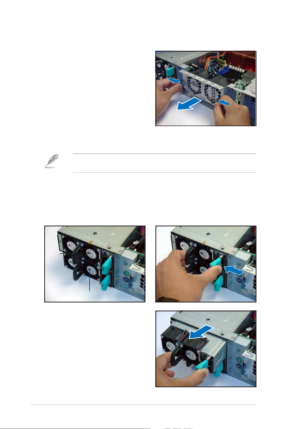
2.7.22.7.2
2.7.2
2.7.22.7.2
To uninstall the rear fans:
1. Remove the top cover screw.
2. Press the rear fan cage levers
inward.
3. Pull the fan cage from the
chassis.
4. Set the rear fan cage aside.
Rear fans (60mm)Rear fans (60mm)
Rear fans (60mm)
Rear fans (60mm)Rear fans (60mm)
2.7.32.7.3
2.7.3
2.7.32.7.3
To uninstall a power supply module:
1. Locate the power supply
modules on the rear panel, and
select the module that you want
to remove.
PSU1PSU1
PSU1
PSU1PSU1
Power supply modulesPower supply modules
Power supply modules
Power supply modulesPower supply modules
The barebone system ships with one power supply module. You may
purchase a second power supply module for redundancy.
2. Hold the module lever and
press the latch on the inner
side to release the module.
PSU2PSU2
PSU2
PSU2PSU2
3. Firmly pull the lever to slide the
power supply module out of the
chassis.
4. Repeat steps 2 to 3 to remove
the other module.
2-342-34
2-34
2-342-34
Chapter 2: Hardware setupChapter 2: Hardware setup
Chapter 2: Hardware setup
Chapter 2: Hardware setupChapter 2: Hardware setup
Page 55

2.7.42.7.4
2.7.4
2.7.42.7.4
Slim optical and floppy drivesSlim optical and floppy drives
Slim optical and floppy drives
Slim optical and floppy drivesSlim optical and floppy drives
To uninstall the optical and floppy disk drives:
1. Disconnect the power and signal
cables connected to the rear of
the drives.
Signal cableSignal cable
Signal cable
Signal cableSignal cable
Power cablePower cable
Power cable
Power cablePower cable
2. Loosen the screws that secure
the drive bracket to the chassis.
The optical drive is attached to
the top of the bracket, and the
floppy drive to bottom.
3. Slide the drive bracket toward
the SCSI backplanes to release it
from the chassis, then carefully
pull it out of the drive bay.
ASUS AP2400R-E2ASUS AP2400R-E2
ASUS AP2400R-E2
ASUS AP2400R-E2ASUS AP2400R-E2
2-352-35
2-35
2-352-35
Page 56

2.7.52.7.5
2.7.5
2.7.52.7.5
Front panel LED and switch boardFront panel LED and switch board
Front panel LED and switch board
Front panel LED and switch boardFront panel LED and switch board
To uninstall the front panel and swtich board:
1. Disconnect all cables connected to the rear of the board.
2. Remove the three screws the secure the board to the chassis.
3. Carefully remove the board out of the chassis.
When removed, the LED and switch board appears as shown. The LEDs and
switches on the board correspond to the LEDs and buttons on the system
front panel.
Locator switch connectorLocator switch connector
Locator switch connector
Locator switch connectorLocator switch connector
Panel connectorPanel connector
Panel connector
Panel connectorPanel connector
Front USB connectorFront USB connector
Front USB connector
Front USB connectorFront USB connector
Front sideFront side
Front side
Front sideFront side
2.7.62.7.6
2.7.6
2.7.62.7.6
SCSI backplanesSCSI backplanes
SCSI backplanes
SCSI backplanesSCSI backplanes
To uninstall a SCSI backplane:
1. Disconnect all cables connected
to the rear of the SCSI
backplane.
2. Carefully push the backplane
upward to remove it from the
chassis.
3. Repeat steps 1 to 2 to remove
the other backplanes.
2-362-36
2-36
2-362-36
Rear sideRear side
Rear side
Rear sideRear side
Chapter 2: Hardware setupChapter 2: Hardware setup
Chapter 2: Hardware setup
Chapter 2: Hardware setupChapter 2: Hardware setup
Page 57

Chapter 3
This chapter describes how to
install optional components and
devices into the barebone server.
ASUS AP2400R-E2ASUS AP2400R-E2
ASUS AP2400R-E2
ASUS AP2400R-E2ASUS AP2400R-E2
Installation options
1-1
Page 58

3.1 Rackmount rail kit items
Your rackmount rail kit package contains:
• one pair of server rails (for the server)
• two pairs of rack rails (for the rack)
* to accommodate different sizes of rack
• Nut-and-bolt type screws
Rear endRear end
Rear end
Rear endRear end
Server railsServer rails
Server rails
Server railsServer rails
Rack railsRack rails
Rack rails
Rack railsRack rails
Front endFront end
Front end
Front endFront end
Nuts-and-screwsNuts-and-screws
Nuts-and-screws
Nuts-and-screwsNuts-and-screws
• The rear ends come pre-installed in the rack rails. The rear end nuts
and screws are loosen to allow flexible installation on the industrial
rack.
• Install the server in an industrial rack with at least 100 cm depth.
3-23-2
3-2
3-23-2
Chapter 3: Installation optionsChapter 3: Installation options
Chapter 3: Installation options
Chapter 3: Installation optionsChapter 3: Installation options
Page 59

3.2 Attaching the rails to the server
To attach the server rails:
1. Locate the hooks on the side of
the chassis.
2. Position a server rail parallel to
the side of the chassis, and
match each of the five hooks to
the holes on the rail.
Side hook lockedSide hook locked
Side hook locked
Side hook lockedSide hook locked
to rail holeto rail hole
to rail hole
to rail holeto rail hole
3. Secure the server rail to the side
of the chassis with two screws.
4. Repeat steps 1 to 3 to attach the second server rail to the other side
of the chassis.
ASUS AP2400R-E2ASUS AP2400R-E2
ASUS AP2400R-E2
ASUS AP2400R-E2ASUS AP2400R-E2
3-33-3
3-3
3-33-3
Page 60

3.3 Attaching the rack rails
To attach the rack rails:
1. Select two units of space (2U) on the rack where you want to install
the barebone server.
2. Install the nuts on the holes of the 2U space on the rack front.
3. Install the nuts on the holes of the 2U space on the corresponding
rack rear.
4. Measure the depth of the rack to
determine the length of the rack
rails.
5. Take two pieces of rack rail,
consisting of the middle piece
Middle pieceMiddle piece
Middle piece
with the pre-installed rear end,
and one front end (left or right).
Middle pieceMiddle piece
Attach the front end to the
middle piece using the supplied
nuts and screws. Make sure that
the front end dent supports the
middle piece.
7. Measure the rack rail when
assembled to make sure that it
fits the rack.
Left frontLeft front
Left front
Left frontLeft front
of the rackof the rack
of the rack
of the rackof the rack
DentDent
Dent
DentDent
Right frontRight front
Right front
Right frontRight front
of the rackof the rack
of the rack
of the rackof the rack
3-43-4
3-4
3-43-4
Chapter 3: Installation optionsChapter 3: Installation options
Chapter 3: Installation options
Chapter 3: Installation optionsChapter 3: Installation options
Page 61

8. Position the rack rail to the 2U
space on the rack. Make sure
that the front end of the rack
rail goes to the front of the rack
space.
9. Secure the front end of the rail
with two rack screws.
10. Secure the rear end of the rail
with two rack screws.
11. Repeat steps 5 to 9 to assemble
and attach the second rack rail.
ASUS AP2400R-E2ASUS AP2400R-E2
ASUS AP2400R-E2
ASUS AP2400R-E2ASUS AP2400R-E2
3-53-5
3-5
3-53-5
Page 62

3.4 Rackmounting the server
To mount the server to the rack:
1. Align the server rails with the rack rails and push the server halfway to
the rack.
2. Align a mounting ear with the
holes on a front corner of the
chassis, then secure it with two
screws.
3. Attach the other mounting ear
to the other corner of the
chassis.
4. Pull the server rail lock, then
push the server all the way to
the depth of the rack.
Make sure that the mounting ear
and the rack screw holes align.
5. Drive a screw on the mounting
ear to secure the server in place.
3-63-6
3-6
3-63-6
Chapter 3: Installation optionsChapter 3: Installation options
Chapter 3: Installation options
Chapter 3: Installation optionsChapter 3: Installation options
Page 63

Chapter 4
This chapter includes the
motherboard layout, and brief
descriptions of the jumpers and
internal connectors.
ASUS AP2400R-E2ASUS AP2400R-E2
ASUS AP2400R-E2
ASUS AP2400R-E2ASUS AP2400R-E2
Motherboard info
1-1
Page 64

4.1 Motherboard layout
33cm (13in)
PS/2
T: Mouse
B: Keyboard
USB1
USB2
COM1
VGA
RJ-45
(LAN-1)
RJ-45
(LAN-2)
Super
USBPW12
AMI
8Mb
FWH
I/O
REAR_FAN2
KBPWR1
REAR_FAN1
RECPVERY1
VGA_EN1
ATXPWR1
PSUSMB1
DDR DIMM_B4 (64/72 bit, 184-pin module)
DDR DIMM_A4 (64/72 bit, 184-pin module)
DDR DIMM_B3 (64/72 bit, 184-pin module)
DDR DIMM_A3 (64/72 bit, 184-pin module)
DDR DIMM_B2 (64/72 bit, 184-pin module)
DDR DIMM_A2 (64/72 bit, 184-pin module)
DDR DIMM_B1 (64/72 bit, 184-pin module)
DDR DIMM_A1 (64/72 bit, 184-pin module)
Broadcom
BCM5721
Intel E7520
MCH
Broadcom
BCM5721
LAN1_EN1
LAN2_EN1
PCIX1 (64-bit, 133MHz 3V)
PCIX2 (64-bit, 133MHz 3V)
ATX12V1
CPU_FAN1
FM_CPU1
J2
Intel
PXH
DSW1
CPU_FAN2
FM_CPU2
mPGA 604
mPGA 604
SEC_IDE
PRI_IDE
Intel
ICH5R
SATA2
SATA1
FRNT_FAN1
FRNT_FAN2
®
NCL-DS1R2
30.5cm (12in)
ATI
RAGE XL
VGA
Controller
SB_PWR1
COM2
BPSMB1
FLOPPY1
BMCCONN1
CR2032 3V
Lithium Cell
CMOS Power
CLRTC1
AUX_PANEL1
BUZZ1
USBPW34
USB34
Intel
PXH
HDLED1
SCSI_EN1
PANEL1
Adaptec
AIC-7902W
34 1
3568
SCSIB1
SCSIA1
4-24-2
4-2
4-24-2
Chapter 4: Motherboard informationChapter 4: Motherboard information
Chapter 4: Motherboard information
Chapter 4: Motherboard informationChapter 4: Motherboard information
Page 65

Layout contentsLayout contents
Layout contents
Layout contentsLayout contents
Switches/JumpersSwitches/Jumpers
Switches/Jumpers
Switches/JumpersSwitches/Jumpers
1. Clear RTC RAM (CLRTC1) 4-4
2. CPU fan pin selection (3-pin FM_CPU1, FM_CPU2) 4-5
3. USB device wake-up (3-pin USBPW12, USBPW34) 4-5
4. Keyboard power (3-pin KBPWR1) 4-6
5. VGA controller setting (3-pin VGA_EN1) 4-6
6. Gigabit LAN1 controller setting (3-pin LAN1_EN1) 4-7
7. Gigabit LAN2 controller setting (3-pin LAN2_EN1) 4-7
8. SCSI controller setting (3-pin SCSI_EN1) 4-8
9. Force BIOS recovery setting (3-pin RECOVERY1) 4-8
ConnectorsConnectors
Connectors
ConnectorsConnectors
1. Floppy disk drive connector (34-1 pin FLOPPY1) 4-9
2. Hard disk activity LED connector (4-pin HDLED1) 4-9
3. Primary IDE connectors (40-1 pin PRI_IDE, SEC_IDE) 4-10
4. Power supply SMBus connector (5-pin PSUSMB1) 4-10
5. Serial ATA connectors (7-pin SATA1, SATA2) 4-11
6. Ultra320 SCSI connectors (two 68-pin SCSIA1, SCSIB1) 4-12
7. USB connector (10-1 pin USB34) 4-13
8. CPU and system fan connectors 4-13
(3-pin CPU_FAN1/2, REAR_FAN1/2, FRNT_FAN1/2)
9. BMC connector (16-pin BMCCONN1) 4-14
10. ATX power connectors (24-pin ATXPWR1, 8-pin ATX12V1) 4-14
11. Backplane SMBus connector (6-1 pin BPSMB1) 4-15
12. System panel connector (20-pin PANEL1) 4-15
13. Auxiliary panel connector (20-pin AUX_PANEL1) 4-16
ASUS AP2400R-E2ASUS AP2400R-E2
ASUS AP2400R-E2
ASUS AP2400R-E2ASUS AP2400R-E2
4-34-3
4-3
4-34-3
Page 66

4.2 Jumpers
1.1.
Clear RTC RAM (CLRTC1)Clear RTC RAM (CLRTC1)
1.
Clear RTC RAM (CLRTC1)
1.1.
Clear RTC RAM (CLRTC1)Clear RTC RAM (CLRTC1)
This jumper allows you to clear the Real Time Clock (RTC) RAM in
CMOS. You can clear the CMOS memory of date, time, and system
setup parameters by erasing the CMOS RTC RAM data. The onboard
button cell battery powers the RAM data in CMOS, which include
system setup information such as system passwords.
To erase the RTC RAM:
1. Turn OFF the computer and unplug the power cord.
2. Remove the onboard battery.
3. Move the jumper cap from pins 1-2 (default) to pins 2-3. Keep
the cap on pins 2-3 for about 5~10 seconds, then move the cap
back to pins 1-2.
4. Re-install the battery.
5. Plug the power cord and turn ON the computer.
6. Hold down the <Del> key during the boot process and enter BIOS
setup to re-enter data.
Except when clearing the RTC RAM, never remove the cap on CLRTC
jumper default position. Removing the cap will cause system boot failure!
®
NCL-DS1R2
CLRTC1
23
Clear CMOS
NCL-DS1R2 Clear RTC RAM
12
Normal
(Default)
4-44-4
4-4
4-44-4
Chapter 4: Motherboard informationChapter 4: Motherboard information
Chapter 4: Motherboard information
Chapter 4: Motherboard informationChapter 4: Motherboard information
Page 67

2.2.
CPU fan pin selection (3-pin FM_CPU1, FM_CPU2)CPU fan pin selection (3-pin FM_CPU1, FM_CPU2)
2.
CPU fan pin selection (3-pin FM_CPU1, FM_CPU2)
2.2.
CPU fan pin selection (3-pin FM_CPU1, FM_CPU2)CPU fan pin selection (3-pin FM_CPU1, FM_CPU2)
These jumpers allow you to connect either a 3-pin or a 4-pin fan cable
plug to the CPU fan connectors (CPU_FAN1, CPU_FAN2). Set these
jumpers to pins 1-2 if you are using a 3-pin fan cable plug, or to pins
2-3 if you are using a 4-pin plug.
FM_CPU1
3
22
1
®
NCL-DS1R2
DC mode PWM
(Default)
FM_CPU2
3
22
1
DC mode PWM
NCL-DS1R2 FM_CPU setting
3.3.
USB device wake-up (3-pin USBPW12, USBPW34)USB device wake-up (3-pin USBPW12, USBPW34)
3.
USB device wake-up (3-pin USBPW12, USBPW34)
3.3.
USB device wake-up (3-pin USBPW12, USBPW34)USB device wake-up (3-pin USBPW12, USBPW34)
(Default)
Set these jumpers to +5V to wake up the computer from S1 sleep
mode (CPU stopped, DRAM refreshed, system running in low power
mode) using the connected USB devices. Set to +5VSB to wake up
from S4 sleep mode (no power to CPU, DRAM in slow refresh, power
supply in reduced power mode).
USBPW12
12 23
+5V +5VSB
®
NCL-DS1R2
NCL-DS1R2 USB device wake up
(Default)
USBPW34
2
1
+5V +5VSB
(Default)
3
2
• The USB device wake-up feature requires a power supply that can
provide 500mA on the +5VSB lead for each USB port; otherwise, the
system would not power up.
• If you are using Windows 2000, you need to install Service Pack 4 to
wake up the system from S4 sleep mode.
• The total current consumed must NOT exceed the power supply
capability (+5VSB) whether under normal condition or in sleep mode.
ASUS AP2400R-E2ASUS AP2400R-E2
ASUS AP2400R-E2
ASUS AP2400R-E2ASUS AP2400R-E2
4-54-5
4-5
4-54-5
Page 68
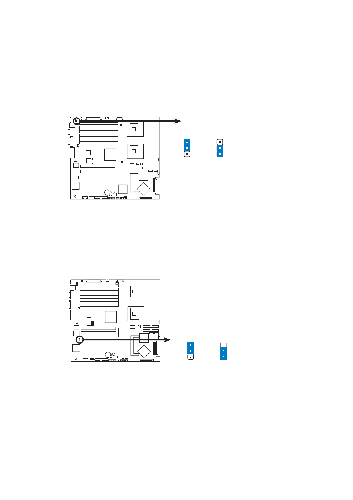
4.4.
Keyboard power (3-pin KBPWR1)Keyboard power (3-pin KBPWR1)
4.
Keyboard power (3-pin KBPWR1)
4.4.
Keyboard power (3-pin KBPWR1)Keyboard power (3-pin KBPWR1)
This jumper allows you to enable or disable the keyboard wake-up
feature. Set this jumper to pins 2-3 (+5VSB) to wake up the computer
when you press a key on the keyboard (the default is the Space Bar).
This feature requires an ATX power supply that can supply at least 1A
on the +5VSB lead, and a corresponding setting in the BIOS.
KBPWR1
1
2
®
NCL-DS1R2
(Default)
NCL-DS1R2 Keyboard power setting
+5V +5VSB
2
3
5.5.
VGA controller setting (3-pin VGA_EN1)VGA controller setting (3-pin VGA_EN1)
5.
VGA controller setting (3-pin VGA_EN1)
5.5.
VGA controller setting (3-pin VGA_EN1)VGA controller setting (3-pin VGA_EN1)
These jumpers allow you to enable or disable the onboard ATI
RAGE-XL PCI VGA controller. Set to pins 1-2 to activate the VGA
feature.
®
NCL-DS1R2
NCL-DS1R2 VGA setting
VGA_EN1
1
Enable
(Default)
22
3
Disable
®
4-64-6
4-6
4-64-6
Chapter 4: Motherboard informationChapter 4: Motherboard information
Chapter 4: Motherboard information
Chapter 4: Motherboard informationChapter 4: Motherboard information
Page 69
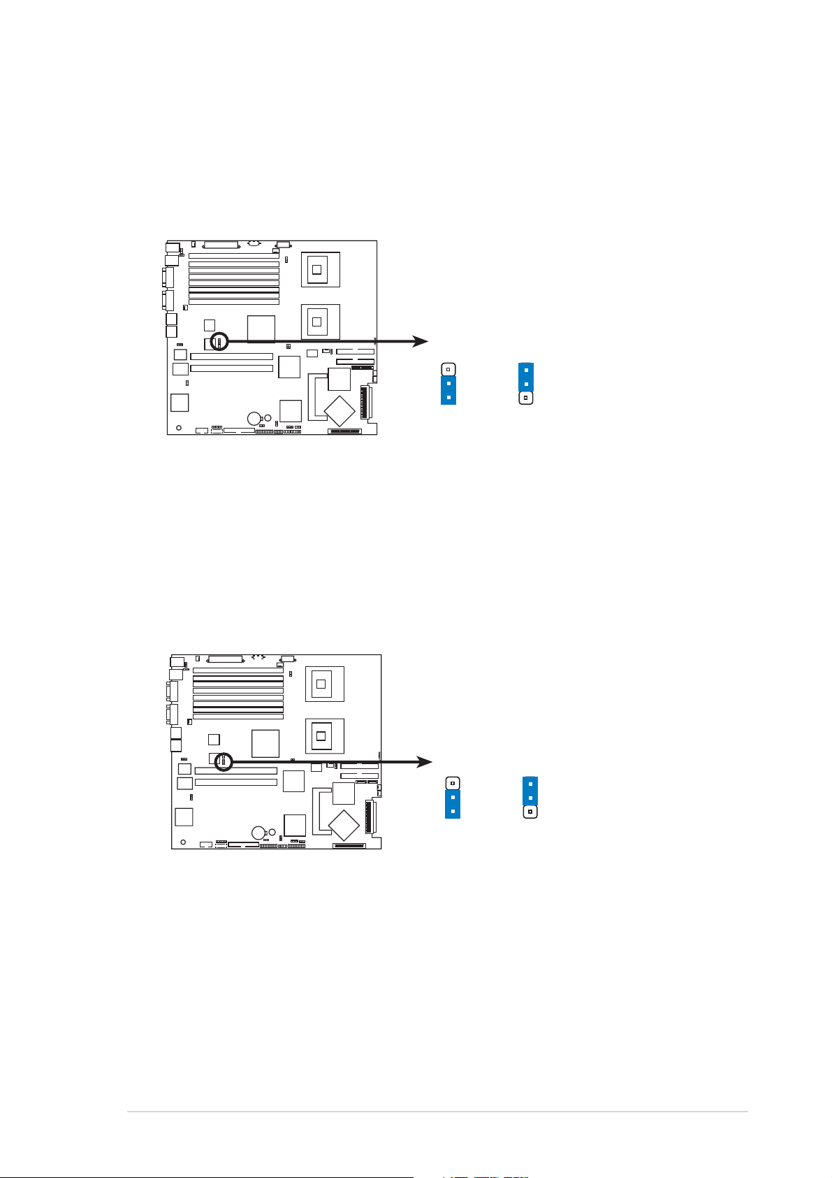
6.6.
Gigabit LAN1 controller setting (3-pin LAN1_EN1)Gigabit LAN1 controller setting (3-pin LAN1_EN1)
6.
Gigabit LAN1 controller setting (3-pin LAN1_EN1)
6.6.
Gigabit LAN1 controller setting (3-pin LAN1_EN1)Gigabit LAN1 controller setting (3-pin LAN1_EN1)
This jumper allows you to enable or disable the onboard Broadcom
BCM5721 Gigabit LAN1 controller. Set to pins 1-2 to activate the
Gigabit LAN feature.
®
®
NCL-DS1R2
LAN1_EN1
1
Enable
(Default)
3
22
Disable
NCL-DS1R2 LAN1_EN setting
7.7.
Gigabit LAN2 controller setting (3-pin LAN2_EN1)Gigabit LAN2 controller setting (3-pin LAN2_EN1)
7.
Gigabit LAN2 controller setting (3-pin LAN2_EN1)
7.7.
Gigabit LAN2 controller setting (3-pin LAN2_EN1)Gigabit LAN2 controller setting (3-pin LAN2_EN1)
These jumpers allow you to enable or disable the onboard Broadcom
BCM5721 Gigabit LAN2 controller. Set to pins 1-2 to activate the
Gigabit LAN feature.
®
NCL-DS1R2 LAN2_EN setting
ASUS AP2400R-E2ASUS AP2400R-E2
ASUS AP2400R-E2
ASUS AP2400R-E2ASUS AP2400R-E2
®
NCL-DS1R2
LAN2_EN1
1
Enable
(Default)
3
22
Disable
4-74-7
4-7
4-74-7
Page 70
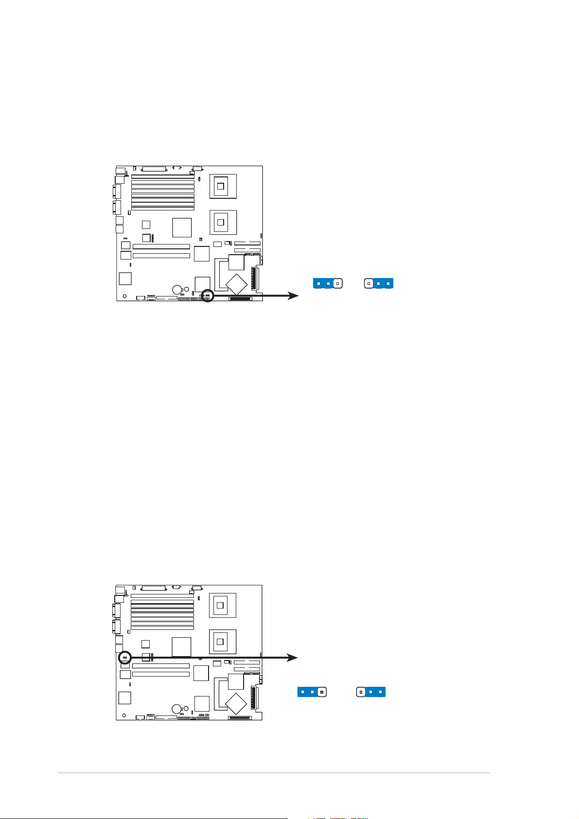
8.8.
SCSI controller setting (3-pin SCSI_EN1)SCSI controller setting (3-pin SCSI_EN1)
8.
SCSI controller setting (3-pin SCSI_EN1)
8.8.
SCSI controller setting (3-pin SCSI_EN1)SCSI controller setting (3-pin SCSI_EN1)
This jumper allows you to enable or disable the onboard Adaptec
®
AIC-7902W SCSI U320 controller. Set to pins 1-2 to activate the SCSI
feature, and support RAID configurations.
®
NCL-DS1R2
SCSI_EN1
12
Enable
(Default)
23
Disable
NCL-DS1R2 SCSI setting
9.9.
Force BIOS recovery setting (3-pin RECOVERY1)Force BIOS recovery setting (3-pin RECOVERY1)
9.
Force BIOS recovery setting (3-pin RECOVERY1)
9.9.
Force BIOS recovery setting (3-pin RECOVERY1)Force BIOS recovery setting (3-pin RECOVERY1)
This jumper allows you to quickly update or recover the BIOS settings
when it becomes corrupted.
To update the BIOS:
1. Prepare a floppy disk that contains the latest BIOS for the
motherboard (xxxx-xxx.ROM) and the AFUDOS.EXE utility.
2. Set the jumper to pins 2-3.
3. Insert the floppy disk then turn on the system to update the
BIOS.
4. Shut down the system.
4-84-8
4-8
4-84-8
5. Set the jumper back to pins 1-2.
6. Turn on the system.
®
NCL-DS1R2
NCL-DS1R2 BIOS recovery setting
Chapter 4: Motherboard informationChapter 4: Motherboard information
Chapter 4: Motherboard information
Chapter 4: Motherboard informationChapter 4: Motherboard information
RECOVERY1
12
Normal BIOS Recovery
(Default)
23
Page 71

4.3 Connectors
This section describes the internal connectors on the motherboard.
Refer to section “1.4 Rear panel features” for information on the
external (rear panel) connectors.
1.1.
Floppy disk drive connector (34-1 pin FLOPPY1)Floppy disk drive connector (34-1 pin FLOPPY1)
1.
Floppy disk drive connector (34-1 pin FLOPPY1)
1.1.
Floppy disk drive connector (34-1 pin FLOPPY1)Floppy disk drive connector (34-1 pin FLOPPY1)
This connector supports the provided floppy drive ribbon cable. After
connecting one end to the motherboard, connect the other end to the
floppy drive. (Pin 5 is removed to prevent incorrect insertion when
using ribbon cables with pin 5 plug).
®
NCL-DS1R2
FLOPPY1
PIN 1
NOTE: Orient the red markings on
the floppy ribbon cable to PIN 1.
NCL-DS1R2 Floppy disk drive connector
2.2.
Hard disk activity LED connector (4-pin HDLED1)Hard disk activity LED connector (4-pin HDLED1)
2.
Hard disk activity LED connector (4-pin HDLED1)
2.2.
Hard disk activity LED connector (4-pin HDLED1)Hard disk activity LED connector (4-pin HDLED1)
This connector supplies power to the hard disk drive activity LED. The
read or write activities of any device connected to an add-on SCSI
card or RAID card cause this LED to light up.
HDLED1
®
NCL-DS1R2
1
NCL-DS1R2 SCSI/SATA card activity LED connector
ASUS AP2400R-E2ASUS AP2400R-E2
ASUS AP2400R-E2
ASUS AP2400R-E2ASUS AP2400R-E2
SCSI_ACTLED-
SCSI_ACTLED-
SCSI_ACTLED+
SCSI_ACTLED+
4-94-9
4-9
4-94-9
Page 72

3.3.
Primary IDE connectors (40-1 pin PRI_IDE, SEC_IDE)Primary IDE connectors (40-1 pin PRI_IDE, SEC_IDE)
3.
Primary IDE connectors (40-1 pin PRI_IDE, SEC_IDE)
3.3.
Primary IDE connectors (40-1 pin PRI_IDE, SEC_IDE)Primary IDE connectors (40-1 pin PRI_IDE, SEC_IDE)
These connectors are for an Ultra DMA 100/66 signal cable. The Ultra
DMA 100/66 signal cable has three connectors: a blue connector for
the primary IDE connector on the motherboard, a black connector for
an Ultra DMA 100/66 IDE slave device (optical drive/hard disk drive),
and a gray connector for an Ultra DMA 100/66 IDE master device (hard
disk drive). If you install two hard disk drives, you must configure the
second drive as a slave device by setting its jumper accordingly. Refer
to the hard disk documentation for the jumper settings.
• Pin 20 on the IDE connector is removed to match the covered hole
on the Ultra DMA cable connector. This prevents incorrect insertion
when you connect the IDE cable.
• Use the 80-conductor IDE cable for Ultra DMA 100/66 IDE devices.
®
NCL-DS1R2
SEC_IDE
PRI_IDE
NOTE: Orient the red markings
(usually zigzag) on the IDE
ribbon cable to PIN 1.
NCL-DS1R2 IDE connectors
4.4.
Power supply SMBus connector (5-pin PSUSMB1)Power supply SMBus connector (5-pin PSUSMB1)
4.
Power supply SMBus connector (5-pin PSUSMB1)
4.4.
Power supply SMBus connector (5-pin PSUSMB1)Power supply SMBus connector (5-pin PSUSMB1)
This connector is for the power supply SMB cable, if your power
supply supports the SMBus function.
+3.3V Remote Sense
NC
I2C_7_DATA#
GND
®
NCL-DS1R2
I2C_7_CLK#
PSUSMB1
PIN 1
PIN 1
4-104-10
4-10
4-104-10
NCL-DS1R2 Power supply SMBus connector
Chapter 4: Motherboard informationChapter 4: Motherboard information
Chapter 4: Motherboard information
Chapter 4: Motherboard informationChapter 4: Motherboard information
Page 73

5.5.
Serial ATA connectors (7-pin SATA1, SATA2)Serial ATA connectors (7-pin SATA1, SATA2)
5.
Serial ATA connectors (7-pin SATA1, SATA2)
5.5.
Serial ATA connectors (7-pin SATA1, SATA2)Serial ATA connectors (7-pin SATA1, SATA2)
These connectors are for the Serial ATA signal cables for Serial ATA
hard disk drives.
If you installed Serial ATA hard disk drives, you can create a RAID 0 or
®
RAID 1 configuration with the Intel
Matrix Storage Technology
through the onboard Intel® ICH5R integrated RAID controller.
These connectors are set to
SS
tandard IDE tandard IDE
S
tandard IDE mode, you can connect Serial ATA boot/data hard disk
SS
tandard IDE tandard IDE
Standard IDE Standard IDE
Standard IDE mode by default. In
Standard IDE Standard IDE
drives to these connectors. If you intend to create a Serial ATA RAID set
using these connectors, set the
Configure SATA As Configure SATA As
Configure SATA As item in the BIOS
Configure SATA As Configure SATA As
to [RAID].
®
GND
NCL-DS1R2
GND
RSATA_RXN2
RSATA_RXP2
GND
RSATA_TXP2
RSATA_TXN2
GND
RSATA_RXN1
RSATA_RXP1
GND
RSATA_TXP1
RSATA_TXN1
GND
SATA2 SATA1
NCL-DS1R2 SATA connectors
Important notes on Serial ATAImportant notes on Serial ATA
Important notes on Serial ATA
Important notes on Serial ATAImportant notes on Serial ATA
• You must install Windows
®
2000 Service Pack 4 or the Windows® XP
Service Pack 1 before using Serial ATA hard disk drives. The Serial
ATA RAID feature (RAID 0/RAID 1) is available only if you are using
Windows® 2000/XP.
• Use only two Serial ATA RAID connectors for each RAID 0 or RAID 1
set.
SS
• When using the connectors in
tandard IDE tandard IDE
S
tandard IDE mode, connect the
SS
tandard IDE tandard IDE
primary (boot) hard disk drive to the SATA1 or SATA2 connector.
Refer to the table below for the recommended SATA hard disk drive
connections.
Serial ATA hard disk drive connectionSerial ATA hard disk drive connection
Serial ATA hard disk drive connection
Serial ATA hard disk drive connectionSerial ATA hard disk drive connection
ConnectorConnector
Connector
ConnectorConnector
SATA1SATA1
SATA1
SATA1SATA1
SATA2SATA2
SATA2
SATA2SATA2
ASUS AP2400R-E2ASUS AP2400R-E2
ASUS AP2400R-E2
ASUS AP2400R-E2ASUS AP2400R-E2
SettingSetting
Setting
SettingSetting
MasterMaster
Master
MasterMaster
SlaveSlave
Slave
SlaveSlave
UseUse
Use
UseUse
Boot diskBoot disk
Boot disk
Boot diskBoot disk
Data diskData disk
Data disk
Data diskData disk
4-114-11
4-11
4-114-11
Page 74

6.6.
Ultra320 SCSI connectors (two 68-pin SCSIA1, SCSIB1)Ultra320 SCSI connectors (two 68-pin SCSIA1, SCSIB1)
6.
Ultra320 SCSI connectors (two 68-pin SCSIA1, SCSIB1)
6.6.
Ultra320 SCSI connectors (two 68-pin SCSIA1, SCSIB1)Ultra320 SCSI connectors (two 68-pin SCSIA1, SCSIB1)
This motherboard comes with the Adaptec
®
AIC-7902W SCSI U320
controller that support two 68-Pin Ultra320 SCSI connectors, one for
each of the two channels. Each channel can support a maximum of 15
devices as specified by Ultra320 standards.
SCSIB1
68-Pin Ultra320/
Ultra2-Wide SCSI Connector
®
NCL-DS1R2
35
1
SCSIA1
68-Pin Ultra320/
Ultra2-Wide SCSI Connector
34 1
3568
6834
NCL-DS1R2 Onboard SCSI connectors
SCSI Connection NotesSCSI Connection Notes
SCSI Connection Notes
SCSI Connection NotesSCSI Connection Notes
This motherboard has two 68-Pin Ultra320 SCSI connectors; one for
each of the two channels.
The onboard SCSI chipset incorporates an advanced multimode I/O cell
that supports both single-ended (SE), Ultra2, Ultra160, and Ultra320
devices. With Ultra320 devices, the SCSI bus platform performs at full
Ultra320 speeds (up to 320MB/s) and extended cabling 12m (or 25m
in a point-to-point configuration). When an SE device is attached, the
bus defaults to an SE speed and 1.5m cable length.
Connect SCSI devices as shown. Each channel should have only one
type of SCSI standard (e.g. Ultra320, Ultra160, Ultra2, Ultra-Wide).
Mixing SCSI devices on the same channel decreases performance of
the slower device.
68-pin Internal SCSI Cable (Twisted-Pair Ribbon)
®
Internal SCSI Devices (up to 15 devices)
NCL-DS1R2
68-pin Internal SCSI Cable (Twisted-Pair Ribbon)
Channel A
68-pin Female
Terminator
Channel B
4-124-12
4-12
4-124-12
Internal SCSI Devices (up to 15 devices)
NCL-DS1R2 SCSI connection example
Chapter 4: Motherboard informationChapter 4: Motherboard information
Chapter 4: Motherboard information
Chapter 4: Motherboard informationChapter 4: Motherboard information
68-pin Female
Terminator
Page 75
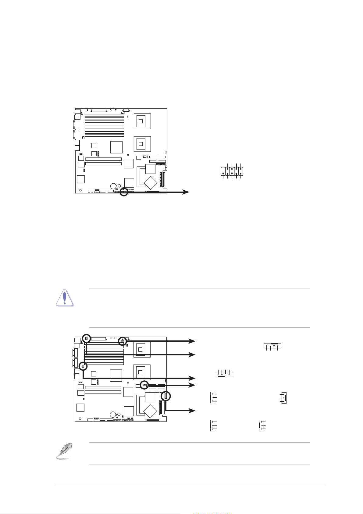
7.7.
USB connector (10-1 pin USB34)USB connector (10-1 pin USB34)
7.
USB connector (10-1 pin USB34)
7.7.
USB connector (10-1 pin USB34)USB connector (10-1 pin USB34)
This connector is for USB 2.0 ports. Connect the USB module cable to
this connector, then install the module to a slot opening at the back
of the system chassis. This USB connector complies with USB 2.0
specification that supports up to 480 Mbps connection speed.
®
Power
USB PortA(-)
USB PortA(+)
NC
GND
GND
1
Power
NCL-DS1R2
USB34
NCL-DS1R2 USB connector
8.8.
CPU and system fan connectors (4-pin CPU_FAN1/2,CPU and system fan connectors (4-pin CPU_FAN1/2,
8.
CPU and system fan connectors (4-pin CPU_FAN1/2,
8.8.
CPU and system fan connectors (4-pin CPU_FAN1/2,CPU and system fan connectors (4-pin CPU_FAN1/2,
3-pin REAR_FAN1/2, FRNT_FAN1/2)3-pin REAR_FAN1/2, FRNT_FAN1/2)
3-pin REAR_FAN1/2, FRNT_FAN1/2)
3-pin REAR_FAN1/2, FRNT_FAN1/2)3-pin REAR_FAN1/2, FRNT_FAN1/2)
USB PortB(-)
USB PortB(+)
The fan connectors support cooling fans of 350 mA ~ 740 mA (8.88 W
max.) or a total of 2.1 A ~ 4.44 A (53.28 W max.) at +12V. Connect
the fan cables to the fan connectors on the motherboard, making sure
that the black wire of each cable matches the ground pin of the
connector.
Do not forget to connect the fan cables to the fan connectors.
Insufficient air flow inside the system may damage the motherboard
components. These are not jumpers! Do not place jumper caps on the
fan connectors!
NCL-DS1R2 Fan connectors
CPU_FAN1
REAR_FAN2
REAR_FAN1
®
CPU_FAN2
NCL-DS1R2
FRNT_FAN1
FRNT_FAN2
CPU_FAN1
GND
FAN Power
FAN Speed
PWM Control
REAR_FAN1
GND
+12V
Rotation
FRNT_FAN1
GND
+12V
Rotation
CPU_FAN2
GND
FAN Power
FAN Speed
PWM Control
REAR_FAN2
Rotation
+12V
GND
FRNT_FAN2
GND
+12V
Rotation
The CPU_FAN1 connector is attached to the mid-fan board. All system
fans will rotate in full speed when you disconnect the CPU_FAN1 cable.
ASUS AP2400R-E2ASUS AP2400R-E2
ASUS AP2400R-E2
ASUS AP2400R-E2ASUS AP2400R-E2
4-134-13
4-13
4-134-13
Page 76

9.9.
BMC connector (16-pin BMCCONN1)BMC connector (16-pin BMCCONN1)
9.
BMC connector (16-pin BMCCONN1)
9.9.
BMC connector (16-pin BMCCONN1)BMC connector (16-pin BMCCONN1)
This connector is for the ASUS server management card, if available.
+5VSB
+5VSB
BMC SMBCLK
12CCLK1
PSON#
BMC_RST#
PWROK
®
BMCCONN1
NCL-DS1R2
PSONEN#
GND
12CDATA1
BMC_SMI#
FP_PWRBTN#
BMC_PRESENT#
-pin -pin
-pin
-pin -pin
ATX12V1ATX12V1
ATX12V1
ATX12V1ATX12V1
10.10.
10.
10.10.
NCL-DS1R2 BMC connector
ATX ATX
ATX
ATX ATX
power connectors (24-pin ATXPWR1,power connectors (24-pin ATXPWR1,
power connectors (24-pin ATXPWR1,
power connectors (24-pin ATXPWR1,power connectors (24-pin ATXPWR1,
+5VSB
+5VSB
BMC SMBDATA
8 8
8
8 8
These connectors are for SSI power supply plugs. The power supply
plugs are designed to fit these connectors in only one orientation.
Find the proper orientation and push down firmly until the connectors
completely fit.
• Use of an SSI 12 V Specification 2.0-compliant power supply unit
(PSU) that provides a minimum power of 450W is recommended for
a fully-configured system.
• Do not forget to connect the 8-pin ATX +12 V power plug;
otherwise, the system will not boot up.
• Use of a PSU with a higher power output is recommended when
configuring a system with more power consuming devices. The
system may become unstable or may not boot up if the power is
inadequate.
))
)
))
4-144-14
4-14
4-144-14
• You must install a PSU with a higher power rating if you intend to
install additional devices.
ATXPWR1 ATX12V1
8-pin
GND12V
GND12V
For Power Supply
with 24-pin
Power Connector
®
NCL-DS1R2
NCL-DS1R2 ATX power connectors
Chapter 4: Motherboard informationChapter 4: Motherboard information
Chapter 4: Motherboard information
Chapter 4: Motherboard informationChapter 4: Motherboard information
24-pin Power Connector
+3 Volts
+3 Volts
Ground
+5 Volts
+5 Volts
Ground
Ground
Power OK
+5V Standby
+3 Volts
-12 Volts
Ground
PSON#
Ground
Ground
-5 Volts
Ground
+5 Volts
+12 Volts
+5 Volts
+12 Volts
+5 Volts
+3 Volts
Ground
GND12V
GND12V
Page 77

11.11.
Backplane SMBus connector (6-1 pin BPSMB1)Backplane SMBus connector (6-1 pin BPSMB1)
11.
Backplane SMBus connector (6-1 pin BPSMB1)
11.11.
Backplane SMBus connector (6-1 pin BPSMB1)Backplane SMBus connector (6-1 pin BPSMB1)
This connector allows you to connect SMBus (System Management
Bus) devices. Devices communicate with an SMBus host and/or other
SMBus devices using the SMBus interface.
®
NCL-DS1R2
NCL-DS1R2 SMBus connector
12.12.
System panel connector (20-pin PANEL1)System panel connector (20-pin PANEL1)
12.
System panel connector (20-pin PANEL1)
12.12.
System panel connector (20-pin PANEL1)System panel connector (20-pin PANEL1)
BPSMB1
1
FAN_DC
I2C_6_CLK#
GND
I2C_6_DATA#
+5V
This connector supports several chassis-mounted functions.
®
NCL-DS1R2
POWERLED+HDLED+
PANEL1
NCHDLED-
POWERLED-
MLED+NMIBTN#
MLED-GND
NCPOWERBTN#
+5VGND
GNDNC
GNDRESETBTN#
SPKROUTGND
NCL-DS1R2 System panel connector
System power LED (Green 3-pin PLED)System power LED (Green 3-pin PLED)
•
System power LED (Green 3-pin PLED)
System power LED (Green 3-pin PLED)System power LED (Green 3-pin PLED)
This 3-pin connector is for the system power LED. Connect the
chassis power LED cable to this connector. The system power
LED lights up when you turn on the system power, and blinks
when the system is in sleep mode.
Hard disk drive activity LED (Red 2-pin IDE_LED)Hard disk drive activity LED (Red 2-pin IDE_LED)
•
Hard disk drive activity LED (Red 2-pin IDE_LED)
Hard disk drive activity LED (Red 2-pin IDE_LED)Hard disk drive activity LED (Red 2-pin IDE_LED)
This 2-pin connector is for the HDD Activity LED. Connect the
HDD Activity LED cable to this connector. The IDE LED lights up
or flashes when data is read from or written to the HDD.
System warning speaker (Orange 4-pin SPEAKER)System warning speaker (Orange 4-pin SPEAKER)
•
System warning speaker (Orange 4-pin SPEAKER)
System warning speaker (Orange 4-pin SPEAKER)System warning speaker (Orange 4-pin SPEAKER)
This 4-pin connector is for the chassis-mounted system warning
speaker. The speaker allows you to hear system beeps and
warnings.
ASUS AP2400R-E2ASUS AP2400R-E2
ASUS AP2400R-E2
ASUS AP2400R-E2ASUS AP2400R-E2
4-154-15
4-15
4-154-15
Page 78

ATX power button/soft-off button (Yellow 2-pinATX power button/soft-off button (Yellow 2-pin
•
ATX power button/soft-off button (Yellow 2-pin
ATX power button/soft-off button (Yellow 2-pinATX power button/soft-off button (Yellow 2-pin
PWRSW)PWRSW)
PWRSW)
PWRSW)PWRSW)
This connector is for the system power button. Pressing the
power button turns the system on or puts the system in sleep or
soft-off mode depending on the BIOS settings. Pressing the
power switch for more than four seconds while the system is ON
turns the system OFF.
Reset button (Blue 2-pin RESET)Reset button (Blue 2-pin RESET)
•
Reset button (Blue 2-pin RESET)
Reset button (Blue 2-pin RESET)Reset button (Blue 2-pin RESET)
This 2-pin connector is for the chassis-mounted reset button for
system reboot without turning off the system power.
The system panel connector is color-coded for easy connection.
13.13.
Auxiliary panel connector (20-pin AUX_PANEL1)Auxiliary panel connector (20-pin AUX_PANEL1)
13.
Auxiliary panel connector (20-pin AUX_PANEL1)
13.13.
Auxiliary panel connector (20-pin AUX_PANEL1)Auxiliary panel connector (20-pin AUX_PANEL1)
This connector is for additional front panel features including front
panel SMB, locator LED and switch, chassis intrusion, and LAN LEDs.
Front panel SMB (6-1 pin FPSMB)Front panel SMB (6-1 pin FPSMB)
•
Front panel SMB (6-1 pin FPSMB)
Front panel SMB (6-1 pin FPSMB)Front panel SMB (6-1 pin FPSMB)
These leads connect the front panel SMBus cable.
LAN activity LED (2-pin LAN1_LED, LAN2_LED)LAN activity LED (2-pin LAN1_LED, LAN2_LED)
•
LAN activity LED (2-pin LAN1_LED, LAN2_LED)
LAN activity LED (2-pin LAN1_LED, LAN2_LED)LAN activity LED (2-pin LAN1_LED, LAN2_LED)
These leads are for Gigabit LAN activity LEDs on the front panel.
Chassis intrusion (2-1 pin CHASSIS)Chassis intrusion (2-1 pin CHASSIS)
•
Chassis intrusion (2-1 pin CHASSIS)
Chassis intrusion (2-1 pin CHASSIS)Chassis intrusion (2-1 pin CHASSIS)
These leads are for the intrusion detection feature for chassis with
intrusion sensor or microswitch. When you remove any chassis
component, the sensor triggers and sends a high-level signal to
these leads to record a chassis intrusion event. To disable this
feature, place a jumper cap over the CASEOPEN and GND leads.
Locator LED (6-pin LOCATOR)Locator LED (6-pin LOCATOR)
•
Locator LED (6-pin LOCATOR)
Locator LED (6-pin LOCATOR)Locator LED (6-pin LOCATOR)
These leads are for the locator switch and LED on the front panel.
Front panel SMBFront panel SMB
Front panel SMB
Front panel SMBFront panel SMB
NCL-DS1R2
AUX_PANEL1
1
LAN activity LEDLAN activity LED
LAN activity LED
LAN activity LEDLAN activity LED
I2C_4_DATA#LOCATORLED1+
+5VSBLOCATORLED1-
LAN1_LINKACTLED+LOCATORBTN#
I2C_4_CLK#
NC
GNDGND
LAN1_LINKACTLED-GND
LAN2_LINKACTLED-LOCATORLED2-
LAN2_LINKACTLED+LOCATORLED2+
4-164-16
4-16
4-164-16
NCL-DS1R2 Auxiliary panel connector
Chapter 4: Motherboard informationChapter 4: Motherboard information
Chapter 4: Motherboard information
Chapter 4: Motherboard informationChapter 4: Motherboard information
+5VSB
CASEOPEN
ChassisChassis
Chassis
ChassisChassis
intrusionintrusion
intrusion
intrusionintrusion
Locator LEDLocator LED
Locator LED
Locator LEDLocator LED
and switchand switch
and switch
and switchand switch
Page 79

Chapter 5
This chapter tells how to change
the system settings through the
BIOS Setup menus.
ASUS AP2400R-E2ASUS AP2400R-E2
ASUS AP2400R-E2
ASUS AP2400R-E2ASUS AP2400R-E2
BIOS information
1-1
Page 80

5.1 Managing and updating your BIOS
The following utilities allow you to manage and update the motherboard
Basic Input/Output System (BIOS) setup.
ASUS AFUDOS ASUS AFUDOS
1.
ASUS AFUDOS (Updates the BIOS in DOS mode using a bootable
ASUS AFUDOS ASUS AFUDOS
floppy disk.)
ASUS CrashFree BIOS 2 ASUS CrashFree BIOS 2
2.
ASUS CrashFree BIOS 2 (Updates the BIOS using a bootable
ASUS CrashFree BIOS 2 ASUS CrashFree BIOS 2
floppy disk or the motherboard support CD when the BIOS file fails or
gets corrupted.)
ASUS Update ASUS Update
3.
ASUS Update (Updates the BIOS in Windows
ASUS Update ASUS Update
Refer to the corresponding sections for details on these utilities.
Save a copy of the original motherboard BIOS file to a bootable floppy
disk in case you need to restore the BIOS in the future. Copy the original
motherboard BIOS using the ASUS Update or AFUDOS utilities.
®
environment.)
5.1.15.1.1
5.1.1
5.1.15.1.1
Creating a bootable floppy diskCreating a bootable floppy disk
Creating a bootable floppy disk
Creating a bootable floppy diskCreating a bootable floppy disk
1. Do either one of the following to create a bootable floppy disk.
DOS environment
a. Insert a 1.44MB floppy disk into the drive.
b. At the DOS prompt, type format A:/S
then press <Enter>.
Windows® XP environment
a. Insert a 1.44 MB floppy disk to the floppy disk drive.
b. Click
ComputerComputer
Computer.
ComputerComputer
Start Start
Start from the Windows
Start Start
®
desktop, then select
MyMy
My
MyMy
c. Select the 3 1/2 Floppy Drive icon.
d. Click
e.
File File
File from the menu, then select
File File
Floppy DiskFloppy Disk
Floppy Disk window appears.
Floppy DiskFloppy Disk
®®
®
®®
WindowsWindows
Windows
WindowsWindows
disk disk
disk from the format options field, then click
disk disk
XP users: XP users:
XP users: Select
XP users: XP users:
Create an MS-DOS startupCreate an MS-DOS startup
Create an MS-DOS startup
Create an MS-DOS startupCreate an MS-DOS startup
FormatFormat
Format. A
FormatFormat
StartStart
Start.
StartStart
Format 3 1/2Format 3 1/2
Format 3 1/2
Format 3 1/2Format 3 1/2
5-25-2
5-2
5-25-2
Chapter 5: BIOS setupChapter 5: BIOS setup
Chapter 5: BIOS setup
Chapter 5: BIOS setupChapter 5: BIOS setup
Page 81

5.1.25.1.2
5.1.2
5.1.25.1.2
AFUDOS utilityAFUDOS utility
AFUDOS utility
AFUDOS utilityAFUDOS utility
The AFUDOS utility allows you to update the BIOS file in DOS environment
using a bootable floppy disk with the updated BIOS file. This utility also
allows you to copy the current BIOS file that you can use as backup when
the BIOS fails or gets corrupted during the updating process.
Copying the current BIOSCopying the current BIOS
Copying the current BIOS
Copying the current BIOSCopying the current BIOS
To copy the current BIOS file using the AFUDOS utility:
• Make sure that the floppy disk is not write-protected and has at
least 600 KB free space to save the file.
• The succeeding BIOS screens are for reference only. The actual BIOS
screen displays may not be same as shown.
1. Copy the AFUDOS utility (afudos.exe) from the motherboard support
CD to the bootable floppy disk you created earlier.
2. Boot the system in DOS mode, then at the prompt type:
afudos /o[filename]
where the [filename] is any user-assigned filename not more than
eight alphanumeric characters for the main filename and three
alphanumeric characters for the extension name.
A:\>afudos /oOLDBIOS1.rom
Main filenameMain filename
Main filename
Main filenameMain filename
Extension nameExtension name
Extension name
Extension nameExtension name
3. Press <Enter>. The utility copies the current BIOS file to the floppy
disk.
A:\>afudos /oOLDBIOS1.rom
AMI Firmware Update Utility - Version 1.19(ASUS V2.07(03.11.24BB))
Copyright (C) 2002 American Megatrends, Inc. All rights reserved.
Reading flash ..... done
Write to file...... ok
A:\>
The utility returns to the DOS prompt after copying the current BIOS
file.
ASUS AP2400R-E2ASUS AP2400R-E2
ASUS AP2400R-E2
ASUS AP2400R-E2ASUS AP2400R-E2
5-35-3
5-3
5-35-3
Page 82

Updating the BIOS fileUpdating the BIOS file
Updating the BIOS file
Updating the BIOS fileUpdating the BIOS file
To update the BIOS file using the AFUDOS utility:
1. Visit the ASUS website (www.asus.com) and download the latest BIOS
file for the motherboard. Save the BIOS file to a bootable floppy disk.
Write the BIOS filename on a piece of paper. You need to type the exact
BIOS filename at the DOS prompt.
2. Copy the AFUDOS utility (afudos.exe) from the motherboard support
CD to the bootable floppy disk you created earlier.
3. Boot the system in DOS mode, then at the prompt type:
afudos /i[filename]
where [filename] is the latest or the original BIOS file on the bootable
floppy disk.
A:\>afudos /iNCLDS1R2.rom
4. The utility verifies the file and starts updating the BIOS.
A:\>afudos /iNCLDS1R2.ROM
AMI Firmware Update Utility - Version 1.19(ASUS V2.07(03.11.24BB))
Copyright (C) 2002 American Megatrends, Inc. All rights reserved.
WARNING!! Do not turn off power during flash BIOS
Reading file ....... done
Reading flash ...... done
Advance Check ......
Erasing flash ...... done
Writing flash ...... 0x0008CC00 (9%)
Do not shut down or reset the system while updating the BIOS to
prevent system boot failure!
5-45-4
5-4
5-45-4
Chapter 5: BIOS setupChapter 5: BIOS setup
Chapter 5: BIOS setup
Chapter 5: BIOS setupChapter 5: BIOS setup
Page 83

5. The utility returns to the DOS prompt after the BIOS update process is
completed. Reboot the system from the hard disk drive.
A:\>afudos /iNCLDS1R2.ROM
AMI Firmware Update Utility - Version 1.19(ASUS V2.07(03.11.24BB))
Copyright (C) 2002 American Megatrends, Inc. All rights reserved.
WARNING!! Do not turn off power during flash BIOS
Reading file ....... done
Reading flash ...... done
Advance Check ......
Erasing flash ...... done
Writing flash ...... done
Verifying flash .... done
Please restart your computer
A:\>
ASUS AP2400R-E2ASUS AP2400R-E2
ASUS AP2400R-E2
ASUS AP2400R-E2ASUS AP2400R-E2
5-55-5
5-5
5-55-5
Page 84

5.1.35.1.3
5.1.3
5.1.35.1.3
ASUS CrashFree BIOS 2 utilityASUS CrashFree BIOS 2 utility
ASUS CrashFree BIOS 2 utility
ASUS CrashFree BIOS 2 utilityASUS CrashFree BIOS 2 utility
The ASUS CrashFree BIOS 2 is an auto recovery tool that allows you to
restore the BIOS file when it fails or gets corrupted during the updating
process. You can update a corrupted BIOS file using the motherboard
support CD or the floppy disk that contains the updated BIOS file.
• Prepare the motherboard support CD or the floppy disk containing
the updated motherboard BIOS before using this utility.
• Make sure that you rename the original or updated BIOS file in the
floppy disk according the exact name of your motherboard, e.g.
NCLDS1R2.ROMNCLDS1R2.ROM
NCLDS1R2.ROM.
NCLDS1R2.ROMNCLDS1R2.ROM
Recovering the BIOS from a floppy diskRecovering the BIOS from a floppy disk
Recovering the BIOS from a floppy disk
Recovering the BIOS from a floppy diskRecovering the BIOS from a floppy disk
To recover the BIOS from a floppy disk:
1. Turn on the system.
2. Insert the floppy disk with the original or updated BIOS file to the
floppy disk drive.
3. The utility displays the following message and automatically checks
the floppy disk for the original or updated BIOS file.
Bad BIOS checksum. Starting BIOS recovery...
Checking for floppy...
When found, the utility reads the BIOS file and starts flashing the
corrupted BIOS file.
Bad BIOS checksum. Starting BIOS recovery...
Checking for floppy...
Floppy found!
Reading file “NCLDS1R2.ROM”. Completed.
Start flashing...
DO NOT shut down or reset the system while updating the BIOS! Doing
so can cause system boot failure!
4. Restart the system after the utility completes the updating process.
5-65-6
5-6
5-65-6
Chapter 5: BIOS setupChapter 5: BIOS setup
Chapter 5: BIOS setup
Chapter 5: BIOS setupChapter 5: BIOS setup
Page 85

Recovering the BIOS from the support CDRecovering the BIOS from the support CD
Recovering the BIOS from the support CD
Recovering the BIOS from the support CDRecovering the BIOS from the support CD
To recover the BIOS from the support CD:
1. Remove any floppy disk from the floppy disk drive, then turn on the
system.
2. Insert the support CD to the optical drive.
3. The utility displays the following message and automatically checks
the floppy disk for the original or updated BIOS file.
Bad BIOS checksum. Starting BIOS recovery...
Checking for floppy...
When no floppy disk is found, the utility automatically checks the
optical drive for the original or updated BIOS file. The utility then
updates the corrupted BIOS file.
Bad BIOS checksum. Starting BIOS recovery...
Checking for floppy...
Floppy not found!
Checking for CD-ROM...
CD-ROM found!
Reading file “NCLDS1R2.ROM”. Completed.
Start flashing...
DO NOT shut down or reset the system while updating the BIOS! Doing
so can cause system boot failure!
4. Restart the system after the utility completes the updating process.
The recovered BIOS may not be the latest BIOS version for this
motherboard. Visit the ASUS website (www.asus.com) to download the
latest BIOS file.
ASUS AP2400R-E2ASUS AP2400R-E2
ASUS AP2400R-E2
ASUS AP2400R-E2ASUS AP2400R-E2
5-75-7
5-7
5-75-7
Page 86

5.1.45.1.4
5.1.4
5.1.45.1.4
The ASUS Update is a utility that allows you to manage, save, and update
the motherboard BIOS in Windows® environment. The ASUS Update utility
allows you to:
• Save the current BIOS file
• Download the latest BIOS file from the Internet
• Update the BIOS from an updated BIOS file
• Update the BIOS directly from the Internet, and
• View the BIOS version information.
This utility is available in the support CD that comes with the motherboard
package.
Installing ASUS UpdateInstalling ASUS Update
Installing ASUS Update
Installing ASUS UpdateInstalling ASUS Update
ASUS Update utilityASUS Update utility
ASUS Update utility
ASUS Update utilityASUS Update utility
ASUS Update requires an Internet connection either through a network
or an Internet Service Provider (ISP).
To install ASUS Update:
1. Place the support CD in the optical drive. The
2. Click the
VX.XX.XXVX.XX.XX
VX.XX.XX.
VX.XX.XXVX.XX.XX
3. The ASUS Update utility is copied to your system.
Utilities Utilities
Utilities tab, then click
Utilities Utilities
Quit all Microsoft® Windows® applications before you update the BIOS
using this utility.
Install ASUS UpdateInstall ASUS Update
Install ASUS Update
Install ASUS UpdateInstall ASUS Update
Drivers Drivers
Drivers menu appears.
Drivers Drivers
5-85-8
5-8
5-85-8
Chapter 5: BIOS setupChapter 5: BIOS setup
Chapter 5: BIOS setup
Chapter 5: BIOS setupChapter 5: BIOS setup
Page 87

Updating the BIOS through the InternetUpdating the BIOS through the Internet
Updating the BIOS through the Internet
Updating the BIOS through the InternetUpdating the BIOS through the Internet
To update the BIOS through the Internet:
®
1. Launch the ASUS Update utility from the Windows
Start Start
Start >
Start Start
Programs Programs
Programs >
Programs Programs
ASUS ASUS
ASUS >
ASUS ASUS
ASUSUpdate ASUSUpdate
ASUSUpdate >
ASUSUpdate ASUSUpdate
desktop by clicking
ASUSUpdateASUSUpdate
ASUSUpdate. The
ASUSUpdateASUSUpdate
ASUS Update main window appears.
2. Select
the Internet the Internet
the Internet option from the
the Internet the Internet
Update BIOS fromUpdate BIOS from
Update BIOS from
Update BIOS fromUpdate BIOS from
drop-down menu, then click
NextNext
Next.
NextNext
3. Select the ASUS FTP site
nearest you to avoid network
traffic, or click
NextNext
Click
Next.
NextNext
Auto SelectAuto Select
Auto Select.
Auto SelectAuto Select
ASUS AP2400R-E2ASUS AP2400R-E2
ASUS AP2400R-E2
ASUS AP2400R-E2ASUS AP2400R-E2
5-95-9
5-9
5-95-9
Page 88

4. From the FTP site, select the
BIOS version that you wish to
download. Click Next.
5. Follow the screen instructions to
complete the update process.
The ASUS Update utility is
capable of updating itself
through the Internet. Always
update the utility to avail all
its features.
Updating the BIOS through a BIOS fileUpdating the BIOS through a BIOS file
Updating the BIOS through a BIOS file
Updating the BIOS through a BIOS fileUpdating the BIOS through a BIOS file
To update the BIOS through a BIOS file:
®
1. Launch the ASUS Update utility from the Windows
clicking
ASUSUpdateASUSUpdate
ASUSUpdate. The ASUS Update main window appears.
ASUSUpdateASUSUpdate
Start Start
Start >
Start Start
Programs Programs
Programs >
Programs Programs
ASUS ASUS
ASUS >
ASUS ASUS
ASUSUpdate ASUSUpdate
ASUSUpdate >
ASUSUpdate ASUSUpdate
desktop by
2. Select
file file
file option from the drop-down
file file
menu, then click
3. Locate the BIOS file from the
Update BIOS from aUpdate BIOS from a
Update BIOS from a
Update BIOS from aUpdate BIOS from a
NextNext
Next.
NextNext
Open Open
Open window, then click
Open Open
SaveSave
Save.
SaveSave
4. Follow the screen instructions to complete the update process.
5-105-10
5-10
5-105-10
Chapter 5: BIOS setupChapter 5: BIOS setup
Chapter 5: BIOS setup
Chapter 5: BIOS setupChapter 5: BIOS setup
Page 89

5.2 BIOS setup program
This motherboard supports a programmable firmware chip that you can
update using the provided utility described in section
updating your BIOS.”
Use the BIOS Setup program when you are installing a motherboard,
reconfiguring your system, or prompted to “Run Setup”. This section
explains how to configure your system using this utility.
Even if you are not prompted to use the Setup program, you can change
the configuration of your computer in the future. For example, you can
enable the security password feature or change the power management
settings. This requires you to reconfigure your system using the BIOS
Setup program so that the computer can recognize these changes and
record them in the CMOS RAM of the firmware hub.
The firmware hub on the motherboard stores the Setup utility. When you
start up the computer, the system provides you with the opportunity to
run this program. Press <Del>
during the Power-On-Self-Test (POST) to
enter the Setup utility; otherwise, POST continues with its test routines.
“
5.1 Managing and
If you wish to enter Setup after POST, restart the system by pressing
<Ctrl+Alt+Delete>, or by pressing the reset button on the system chassis.
You can also restart by turning the system off and then back on. Do this
last option only if the first two failed.
The Setup program is designed to make it as easy to use as possible. Being
a menu-driven program, it lets you scroll through the various sub-menus
and make your selections from the available options using the navigation
keys.
• The default BIOS settings for this motherboard apply for most
conditions to ensure optimum performance. If the system becomes
unstable after changing any BIOS settings, load the default settings
to ensure system compatibility and stability. Select the
Setup Defaults Setup Defaults
Setup Defaults item under the Exit Menu. See section “5.7 Exit
Setup Defaults Setup Defaults
Menu.”
• The BIOS setup screens shown in this section are for reference
purposes only, and may not exactly match what you see on your
screen.
• Visit the ASUS website (www.asus.com) to download the latest BIOS
file for this motherboard.
LoadLoad
Load
LoadLoad
ASUS AP2400R-E2ASUS AP2400R-E2
ASUS AP2400R-E2
ASUS AP2400R-E2ASUS AP2400R-E2
5-115-11
5-11
5-115-11
Page 90

5.2.15.2.1
5.2.1
5.2.15.2.1
BIOS menu screenBIOS menu screen
BIOS menu screen
BIOS menu screenBIOS menu screen
Menu itemsMenu items
Menu items
Menu itemsMenu items
System Time [11:10:19]
System Date [Fri 08/06/2004]
Legacy Diskette A [1.44M, 3.5 in]
Primary IDE Master : [ST320413A]
Primary IDE Slave : [ASUS CD-S520/A]
Secondary IDE Master : [Not Detected]
Secondary IDE Slave : [Not Detected]
Third IDE/SATA : [Not Detected]
Fourth IDE/SATA : [Not Detected]
IDE Configuration
System Information
Sub-menu itemsSub-menu items
Sub-menu items
Sub-menu itemsSub-menu items
5.2.25.2.2
5.2.2
5.2.25.2.2
Menu barMenu bar
Menu bar
Menu barMenu bar
Menu barMenu bar
Menu bar
Menu barMenu bar
Configuration fieldsConfiguration fields
Configuration fields
Configuration fieldsConfiguration fields
General helpGeneral help
General help
General helpGeneral help
Use [ENTER], [TAB]
or [SHIFT-TAB] to
select a field.
Use [+] or [-] to
configure system time.
Select Screen
Select Item
+- Change Field
Tab Select Field
F1 General Help
F10 Save and Exit
ESC Exit
Navigation keysNavigation keys
Navigation keys
Navigation keysNavigation keys
The menu bar on top of the screen has the following main items:
MainMain
Main For changing the basic system configuration
MainMain
AdvancedAdvanced
Advanced For changing the advanced system settings
AdvancedAdvanced
PowerPower
Power For changing the advanced power management (APM)
PowerPower
configuration
BootBoot
Boot For changing the system boot configuration
BootBoot
ExitExit
Exit For selecting the exit options and loading default
ExitExit
settings
To select an item on the menu bar, press the right or left arrow key on the
keyboard until the desired item is highlighted.
5.2.35.2.3
5.2.3
5.2.35.2.3
Navigation keysNavigation keys
Navigation keys
Navigation keysNavigation keys
At the bottom right corner of a menu screen are the navigation keys for
that particular menu. Use the navigation keys to select items in the menu
and change the settings.
Some of the navigation keys differ from one screen to another.
5-125-12
5-12
5-125-12
Chapter 5: BIOS setupChapter 5: BIOS setup
Chapter 5: BIOS setup
Chapter 5: BIOS setupChapter 5: BIOS setup
Page 91

5.2.45.2.4
5.2.4
5.2.45.2.4
Menu itemsMenu items
Menu items
Menu itemsMenu items
The highlighted item on the menu
bar displays the specific items for
that menu. For example, selecting
Main Main
Main shows the Main menu items.
Main Main
The other items (Advanced, Power,
System Time [11:51:19]
System Date [Thu 05 /07/2004]
Legacy Diskette A [1.44M, 3.5 in]
Primary IDE Master : [ST320413A]
Primary IDE Slave : [ASUS CD-S520/A
Secondary IDE Master : [Not Detected]
Secondary IDE Slave : [Not Detected]
Third IDE/SATA : [Not Detected]
Fourth IDE/SATA : [Not Detected]
IDE Configuration
System Information
Use [ENTER], [TAB]
or [SHIFT-TAB] to
select a field.
Use [+] or [-] to
configure system time.
Select Screen
Select Item
+- Change Field
Tab Select Field
F1 General Help
F10 Save and Exit
ESC Exit
Boot, and Exit) on the menu bar have
Main menu itemsMain menu items
their respective menu items.
5.2.55.2.5
5.2.5
5.2.55.2.5
Sub-menu itemsSub-menu items
Sub-menu items
Sub-menu itemsSub-menu items
Main menu items
Main menu itemsMain menu items
A solid triangle before each item on any menu screen means that the iteam
has a sub-menu. To display the sub-menu, select the item and press
<Enter>.
5.2.65.2.6
5.2.6
5.2.65.2.6
Configuration fieldsConfiguration fields
Configuration fields
Configuration fieldsConfiguration fields
These fields show the values for the menu items. If an item is userconfigurable, you can change the value of the field opposite the item. You
cannot select an item that is not user-configurable.
A configurable field is enclosed in brackets, and is highlighted when
selected. To change the value of a field, select it then press <Enter> to
display a list of options. Refer to “5.2.7 Pop-up window.”
5.2.75.2.7
5.2.7
5.2.75.2.7
Pop-up windowPop-up window
Pop-up window
Pop-up windowPop-up window
Select a menu item then press <Enter> to display a pop-up window with
the configuration options for that item.
5.2.85.2.8
5.2.8
5.2.85.2.8
A scroll bar appears on the right side
of a menu screen when there are items
that do not fit on the screen. Press the
Up/Down arrow keys or <Page Up> /
<Page Down> keys to display the other
Scroll barScroll bar
Scroll bar
Scroll barScroll bar
Advanced Chipset settings
WARNING: Setting wrong values in the sections below
may cause system to malfunction.
Configure DRAM Timing by SPD [Enabled]
Memory Acceleration Mode [Auto]
DRAM Idle Timer [Auto]
DRAm Refresh Rate [Auto]
Graphic Adapter Priority [AGP/PCI]
Graphics Aperture Size [ 64 MB]
Spread Spectrum [Enabled]
ICH Delayed Transaction [Enabled]
MPS Revision [1.4]
Select Screen
Select Item
+- Change Option
F1 General Help
F10 Save and Exit
ESC Exit
items on the screen.
Pop-up windowPop-up window
Pop-up window
Pop-up windowPop-up window
5.2.95.2.9
5.2.9
5.2.95.2.9
At the top right corner of the menu
General helpGeneral help
General help
General helpGeneral help
Scroll barScroll bar
Scroll bar
Scroll barScroll bar
screen is a brief description of the
selected item.
ASUS AP2400R-E2ASUS AP2400R-E2
ASUS AP2400R-E2
ASUS AP2400R-E2ASUS AP2400R-E2
5-135-13
5-13
5-135-13
Page 92

5.3 Main menu
When you enter the BIOS Setup program, the
Main Main
Main menu screen appears,
Main Main
giving you an overview of the basic system information.
Refer to section “5.2.1 BIOS menu screen” for information on the menu
screen items and how to navigate through them.
System Time [11:10:19]
System Date [Fri 08/06/2004]
Legacy Diskette A [1.44M, 3.5 in]
Primary IDE Master : [ST320413A]
Primary IDE Slave : [ASUS CD-S520/A]
Secondary IDE Master : [Not Detected]
Secondary IDE Slave : [Not Detected]
Third IDE/SATA : [Not Detected]
Fourth IDE/SATA : [Not Detected]
IDE Configuration
System Information
Use [ENTER], [TAB]
or [SHIFT-TAB] to
select a field.
Use [+] or [-] to
configure system time.
Select Screen
Select Item
+- Change Field
Tab Select Field
F1 General Help
F10 Save and Exit
ESC Exit
5.3.15.3.1
5.3.1
5.3.15.3.1
System Time [xx:xx:xx]System Time [xx:xx:xx]
System Time [xx:xx:xx]
System Time [xx:xx:xx]System Time [xx:xx:xx]
Allows you to set the system time.
5.3.25.3.2
5.3.2
5.3.25.3.2
System Date [Day xx/xx/xxxx]System Date [Day xx/xx/xxxx]
System Date [Day xx/xx/xxxx]
System Date [Day xx/xx/xxxx]System Date [Day xx/xx/xxxx]
Allows you to set the system date.
5.3.35.3.3
5.3.3
5.3.35.3.3
Legacy Diskette A [1.44M, 3.5 in.]Legacy Diskette A [1.44M, 3.5 in.]
Legacy Diskette A [1.44M, 3.5 in.]
Legacy Diskette A [1.44M, 3.5 in.]Legacy Diskette A [1.44M, 3.5 in.]
Sets the type of floppy drive installed. Configuration options: [Disabled]
[360K, 5.25 in.] [1.2M , 5.25 in.] [720K , 3.5 in.] [1.44M, 3.5 in.]
[2.88M, 3.5 in.]
5-145-14
5-14
5-145-14
Chapter 5: BIOS setupChapter 5: BIOS setup
Chapter 5: BIOS setup
Chapter 5: BIOS setupChapter 5: BIOS setup
Page 93

5.3.45.3.4
5.3.4
5.3.45.3.4
Primary/Secondary IDE Master/Slave,Primary/Secondary IDE Master/Slave,
Primary/Secondary IDE Master/Slave,
Primary/Secondary IDE Master/Slave,Primary/Secondary IDE Master/Slave,
Third and Fourth IDE/SATAThird and Fourth IDE/SATA
Third and Fourth IDE/SATA
Third and Fourth IDE/SATAThird and Fourth IDE/SATA
The BIOS automatically detects the connected IDE devices. There is a
separate sub-menu for each IDE device. Select a device item, then press
<Enter> to display the IDE device information.
Primary IDE Master
Device : Hard Disk
Vendor : ST320413A
Size : 20.0GB
LBA Mode : Supported
Block Mode : 16 Sectors
PIO Mode : Supported
Async DMA : MultiWord DMA-2
Ultra DMA : Ultra DMA-5
SMART Monitoring: Supported
Type [Auto]
LBA/Large Mode [Auto]
Block(Multi-sector Transfer) [Auto]
PIO Mode [Auto]
DMA Mode [Auto]
SMART Monitoring [Auto]
32Bit Data Transfer [Disabled]
Select the type
of device connected
to the system.
Select Screen
Select Item
+- Change Option
F1 General Help
F10 Save and Exit
ESC Exit
The BIOS automatically detects the values opposite the dimmed items
(Device, Vendor, Size, LBA Mode, Block Mode, PIO Mode, Async DMA, Ultra
DMA, and SMART monitoring). These values are not user-configurable.
These items show N/A if no IDE device is installed in the system.
Type [Auto]Type [Auto]
Type [Auto]
Type [Auto]Type [Auto]
Selects the type of IDE drive. Setting to [Auto] allows automatic selection
of the appropriate IDE device type. Select [CDROM] if you are specifically
configuring a CD-ROM drive. Select [ARMD] (ATAPI Removable Media
Device) if your device is either a ZIP, LS-120, or MO drive.
Configuration options: [Not Installed] [Auto] [CDROM] [ARMD]
LBA/Large Mode [Auto]LBA/Large Mode [Auto]
LBA/Large Mode [Auto]
LBA/Large Mode [Auto]LBA/Large Mode [Auto]
Enables or disables the LBA mode. Setting to [Auto] enables the LBA mode
if the device supports this mode, and if the device was not previously
formatted with LBA mode disabled. Configuration options: [Disabled]
[Auto]
Block (Multi-sector Transfer) [Auto]Block (Multi-sector Transfer) [Auto]
Block (Multi-sector Transfer) [Auto]
Block (Multi-sector Transfer) [Auto]Block (Multi-sector Transfer) [Auto]
Enables or disables data multi-sectors transfers. When set to [Auto], the
data transfer from and to the device occurs multiple sectors at a time if
the device supports multi-sector transfer feature. When set to [Disabled],
the data transfer from and to the device occurs one sector at a time.
Configuration options: [Disabled] [Auto]
ASUS AP2400R-E2ASUS AP2400R-E2
ASUS AP2400R-E2
ASUS AP2400R-E2ASUS AP2400R-E2
5-155-15
5-15
5-155-15
Page 94

PIO Mode [Auto]PIO Mode [Auto]
PIO Mode [Auto]
PIO Mode [Auto]PIO Mode [Auto]
Selects the PIO mode. Configuration options: [Auto] [0] [1] [2] [3] [4]
DMA Mode [Auto]DMA Mode [Auto]
DMA Mode [Auto]
DMA Mode [Auto]DMA Mode [Auto]
Selects the DMA mode. Configuration options: [Auto] [SWDMA0]
[SWDMA1] [SWDMA2] [MWDMA0] [MWDMA1] [MWDMA2] [UDMA0]
[UDMA1] [UDMA2]
SMART Monitoring [Auto]SMART Monitoring [Auto]
SMART Monitoring [Auto]
SMART Monitoring [Auto]SMART Monitoring [Auto]
Sets the Smart Monitoring, Analysis, and Reporting Technology.
Configuration options: [Auto] [Disabled] [Enabled]
32Bit Data Transfer [Disabled]32Bit Data Transfer [Disabled]
32Bit Data Transfer [Disabled]
32Bit Data Transfer [Disabled]32Bit Data Transfer [Disabled]
Enables or disables 32-bit data transfer.
Configuration options: [Disabled] [Enabled]
5-165-16
5-16
5-165-16
Chapter 5: BIOS setupChapter 5: BIOS setup
Chapter 5: BIOS setup
Chapter 5: BIOS setupChapter 5: BIOS setup
Page 95

5.3.55.3.5
5.3.5
5.3.55.3.5
IDE ConfigurationIDE Configuration
IDE Configuration
IDE ConfigurationIDE Configuration
The items in this menu allow you to set or change the configurations for
the IDE devices installed in the system. Select an item then press <Enter>
if you wish to configure the item.
IDE Configuration
Onboard IDE Operate Mode [Enhanced Mode]
Enhanced Mode Support On [S-ATA]
Configure S-ATA as RAID [No]
IDE Detect Time Out (Sec) [35]
Onboard IDE Operate Mode [Enhanced Mode]Onboard IDE Operate Mode [Enhanced Mode]
Onboard IDE Operate Mode [Enhanced Mode]
Onboard IDE Operate Mode [Enhanced Mode]Onboard IDE Operate Mode [Enhanced Mode]
When in AHCI/RAID
mode SATA
controller is
forced to Native
mode.
Allows selection of the IDE operation mode depending on the installed
operating system (OS). Set to [Enhanced Mode] if you are using native OS,
e.g. Windows® 2000/XP. Set to [Compatible Mode] if you are using legacy
OS, e.g. Windows ME/98/NT, MS-DOS.
Configuration options: [Compatible Mode] [Enhanced Mode]
The items
as RAIDas RAID
as RAID appear only when you set the Onboard IDE Operate Mode to
as RAIDas RAID
[Enhanced Mode].
Enhanced Mode Support OnEnhanced Mode Support On
Enhanced Mode Support On and
Enhanced Mode Support OnEnhanced Mode Support On
Configure S-ATAConfigure S-ATA
Configure S-ATA
Configure S-ATAConfigure S-ATA
Enhanced Mode Support On [S-ATA]
Allows you to set Serial ATA, Parallel ATA, or both, to native mode.
Configuration options: [P-ATA+S-ATA] [S-ATA] [ P-ATA]
Configure S-ATA as RAID [No]Configure S-ATA as RAID [No]
Configure S-ATA as RAID [No]
Configure S-ATA as RAID [No]Configure S-ATA as RAID [No]
Allows you to configure the Serial ATA devices as RAID sets.
Configuration options: [No] [Yes]
IDE Detect Time Out (Sec) [35]IDE Detect Time Out (Sec) [35]
IDE Detect Time Out (Sec) [35]
IDE Detect Time Out (Sec) [35]IDE Detect Time Out (Sec) [35]
Selects the time our value (in seconds) for detecting ATA/ATAPI devices.
Configuration options: [0] [5] [10] [15] [20] [25] [30] [35]
ASUS AP2400R-E2ASUS AP2400R-E2
ASUS AP2400R-E2
ASUS AP2400R-E2ASUS AP2400R-E2
5-175-17
5-17
5-175-17
Page 96

5.3.65.3.6
5.3.6
5.3.65.3.6
System InformationSystem Information
System Information
System InformationSystem Information
This menu gives you an overview of the general system specifications. The
BIOS automatically detects the items in this menu.
AMIBIOS
Version : 08.00.10
Build Date : 07/23/04
Processor
Type : Intel(R) Xeon(TM) CPU 2.80GHz
Speed : 2800 MHz
Count : 2
System Memory
Size : 512MB
Select Screen
Select Item
+- Change Option
F1 General Help
F10 Save and Exit
ESC Exit
AMI BIOSAMI BIOS
AMI BIOS
AMI BIOSAMI BIOS
Displays the auto-detected BIOS information.
ProcessorProcessor
Processor
ProcessorProcessor
Displays the auto-detected CPU specification.
System MemorySystem Memory
System Memory
System MemorySystem Memory
Displays the auto-detected system memory.
5-185-18
5-18
5-185-18
Chapter 5: BIOS setupChapter 5: BIOS setup
Chapter 5: BIOS setup
Chapter 5: BIOS setupChapter 5: BIOS setup
Page 97
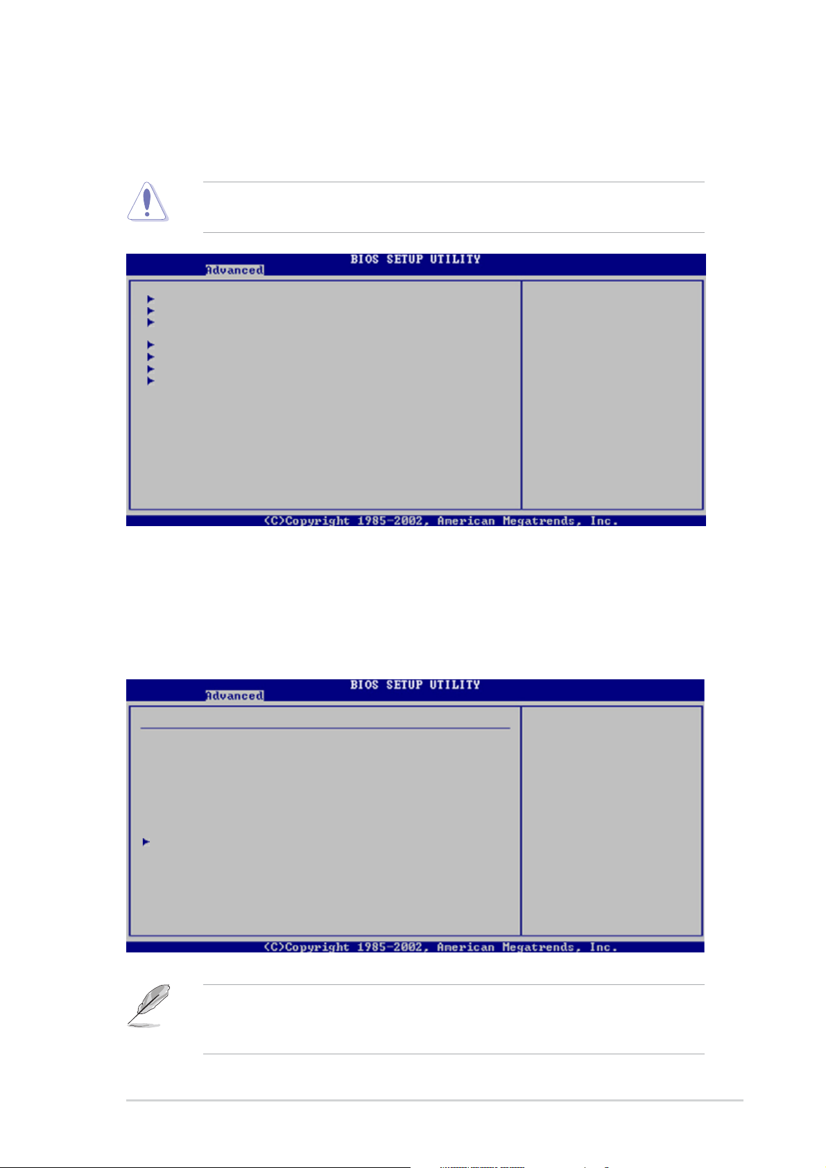
5.4 Advanced menu
The Advanced menu items allow you to change the settings for the CPU
and other system devices.
Take caution when changing the settings of the Advanced menu items.
Incorrect field values can cause the system to malfunction.
USB Configuration
MPS Configuration
Remote Access Configuration
CPU Configuration
Chipset
Onboard Devices Configuration
PCI PnP
5.4.15.4.1
5.4.1
5.4.15.4.1
USB ConfigurationUSB Configuration
USB Configuration
USB ConfigurationUSB Configuration
Configure the USB
support.
The items in this menu allows you to change the USB-related features.
Select an item then press <Enter> to display the configuration options.
USB Configuration
Module Version - 2.23.2-5.3
USB Devices Enabled: None
USB Function [4 USB Ports]
Legacy USB Support [Auto]
USB 2.0 Controller [Enabled]
USB 2.0 Controller Mode [HiSpeed]
USB Mass Storage Device Configuration
Module VersionModule Version
The
Module Version and
Module VersionModule Version
auto-detected values. If no USB device is detected, the
Enabled Enabled
Enabled item shows
Enabled Enabled
ASUS AP2400R-E2ASUS AP2400R-E2
ASUS AP2400R-E2
ASUS AP2400R-E2ASUS AP2400R-E2
NoneNone
None.
NoneNone
Enables USB host
controllers.
USB Devices Enabled USB Devices Enabled
USB Devices Enabled items show the
USB Devices Enabled USB Devices Enabled
USB DevicesUSB Devices
USB Devices
USB DevicesUSB Devices
5-195-19
5-19
5-195-19
Page 98

USB Function [4 USB Ports]USB Function [4 USB Ports]
USB Function [4 USB Ports]
USB Function [4 USB Ports]USB Function [4 USB Ports]
Allows you to enable a specific number of USB ports, or disable the USB
function. Configuration options: [Disabled] [2 USB Ports] [4 USB Ports]
Legacy USB Support [Auto]Legacy USB Support [Auto]
Legacy USB Support [Auto]
Legacy USB Support [Auto]Legacy USB Support [Auto]
Allows you to enable or disable support for legacy USB devices. Setting to
[Auto] allows the system to detect the presence of legacy USB devices at
startup. If detected, the USB controller legacy mode is enabled. If no legacy
USB device is detected, the legacy USB support is disabled.
Configuration options: [Disabled] [Enabled] [Auto]
USB 2.0 Controller [Enabled]USB 2.0 Controller [Enabled]
USB 2.0 Controller [Enabled]
USB 2.0 Controller [Enabled]USB 2.0 Controller [Enabled]
Allows you to enable or disable the USB 2.0 controller.
Configuration options: [Enabled] [Disabled]
USB 2.0 Controller Mode [HiSpeed]USB 2.0 Controller Mode [HiSpeed]
USB 2.0 Controller Mode [HiSpeed]
USB 2.0 Controller Mode [HiSpeed]USB 2.0 Controller Mode [HiSpeed]
Allows you to set the USB 2.0 controller mode to HiSpeed (480 Mbps) or
FullSpeed (12 Mbps). Configuration options: [FullSpeed ] [HiSpeed]
USB Mass Storage Device ConfigurationUSB Mass Storage Device Configuration
USB Mass Storage Device Configuration
USB Mass Storage Device ConfigurationUSB Mass Storage Device Configuration
USB Mass Storage Device Configuration
USB Mass Storage Reset Delay [20 Seconds]
No USB Mass Storage device detected
Device #1 N/A
Emulation Type [N/A]
Device #2 N/A
Emulation Type [N/A]
Device #3 N/A
Emulation Type [N/A]
Device #4 N/A
Emulation Type [N/A]
Device #5 N/A
Emulation Type [N/A]
Device #6 N/A
Emulation Type [N/A]
Number of seconds
POST waits fro the
USB mass storage
device after start
unit command.
Select Screen
Select Item
+- Change Option
F1 General Help
F10 Save and Exit
ESC Exit
USB Mass Storage Reset Delay [20 Sec]
Allows you to select the number of seconds POST waits for the USB
mass storage device after the start unit command. The message “No
USB mass storage device detected” appears if none is installed in the
system. Configuration options: [10 Sec ] [20 Sec] [30 Sec] [40 Sec]
5-205-20
5-20
5-205-20
Chapter 5: BIOS setupChapter 5: BIOS setup
Chapter 5: BIOS setup
Chapter 5: BIOS setupChapter 5: BIOS setup
Page 99
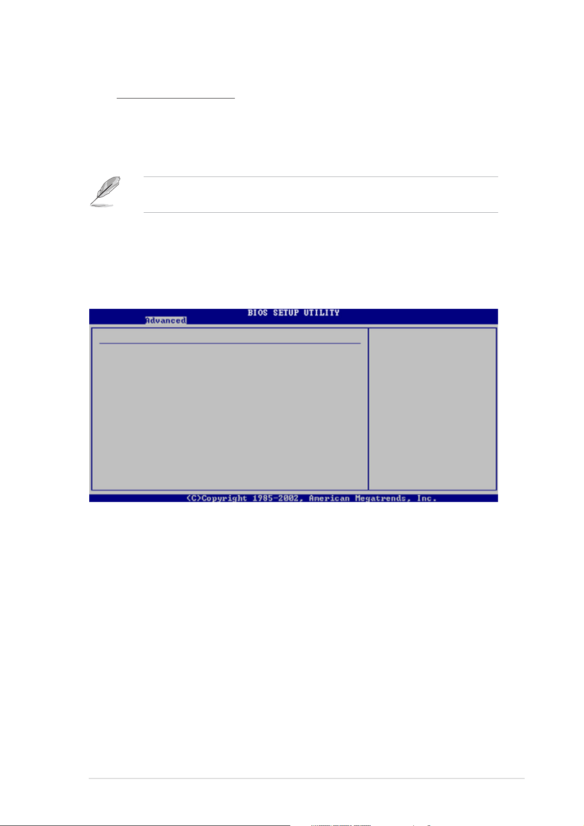
Emulation Type [N/A]
When set to Auto, USB devices less than 530MB will be emulated as
floppy drive, and the remaining drives as hard drives. Forced FDD
option can be used to force an HDD formatted drive to boot as FDD
(for example, ZIP drive).
The Device and Emulation Type items appear only when there are
installed USB devices.
5.4.25.4.2
5.4.2
5.4.25.4.2
MPS ConfigurationMPS Configuration
MPS Configuration
MPS ConfigurationMPS Configuration
The items in this menu allows you to configure the Multi-Processor Table.
Select an item then press <Enter> to display the configuration options.
MPS Configuration
MPS Revision [1.4]
MPS Revision [1.4]MPS Revision [1.4]
MPS Revision [1.4]
MPS Revision [1.4]MPS Revision [1.4]
Select MPS Revision.
Allows you to select the multi-processor system version.
Configuration options: [1.1] [1.4]
ASUS AP2400R-E2ASUS AP2400R-E2
ASUS AP2400R-E2
ASUS AP2400R-E2ASUS AP2400R-E2
5-215-21
5-21
5-215-21
Page 100

5.4.35.4.3
5.4.3
5.4.35.4.3
Remote Access ConfigurationRemote Access Configuration
Remote Access Configuration
Remote Access ConfigurationRemote Access Configuration
The items in this menu allows you to configure the Remote Access
features. Select an item then press <Enter> to display the configuration
options.
Configure Remote Access type and parameters
Remote Access [Disabled]
Remote Access [Disabled]Remote Access [Disabled]
Remote Access [Disabled]
Remote Access [Disabled]Remote Access [Disabled]
Select Remote Access
type.
Enables or disables the remote access feature. Setting this item to
[Enabled] displays other connectivity items (see the screen below).
Configuration options: [Disabled] [Enabled]
Configure Remote Access type and parameters
Remote Access [Enabled]
Serial port number [COM1]
Serial Port Mode [115200 8,n,1]
Flow Control [None]
Redirection After BIOS POST [Always]
Terminal Type [ANSI]
VT-UTFB Combo Key Support [Disabled]
Select Remote Access
type.
Serial port number [COM1]Serial port number [COM1]
Serial port number [COM1]
Serial port number [COM1]Serial port number [COM1]
Enables or disables the remote access feature.
Configuration options: [Disabled] [Enabled]
Serial Port Mode [115200 8,n,1]Serial Port Mode [115200 8,n,1]
Serial Port Mode [115200 8,n,1]
Serial Port Mode [115200 8,n,1]Serial Port Mode [115200 8,n,1]
Sets the Serial port mode.
Configuration options: [115200 8,n,1] [57600 8,n,1] [38400 8,n,1]
[19200 8,n,1] [09600 8,n,1]
Flow Control [None]Flow Control [None]
Flow Control [None]
Flow Control [None]Flow Control [None]
Allows you to select the flow control for console redirection.
Configuration options: [None] [Hardware] [Software]
5-225-22
5-22
5-225-22
Chapter 5: BIOS setupChapter 5: BIOS setup
Chapter 5: BIOS setup
Chapter 5: BIOS setupChapter 5: BIOS setup
 Loading...