

Page 1
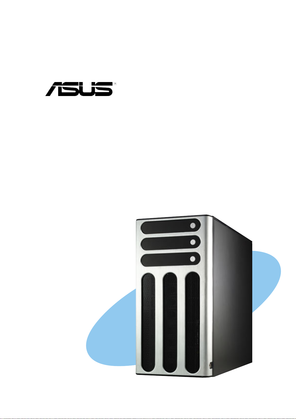
AP1720-E2
Dual Intel® Xeon™ 5U Rackmount Server
800/533MHz Front Side Bus
User Guide
Page 2

E1733
First Edition V1
October 2004
Copyright © 2004 ASUSTeK COMPUTER INC. All Rights Reserved.
No part of this manual, including the products and software described in it, may be
reproduced, transmitted, transcribed, stored in a retrieval system, or translated into any
language in any form or by any means, except documentation kept by the purchaser for
backup purposes, without the express written permission of ASUSTeK COMPUTER INC.
(“ASUS”).
ASUS provides this manual “as is” without warranty of any kind, either express or implied,
including but not limited to the implied warranties or conditions of merchantability or fitness
for a particular purpose. In no event shall ASUS, its directors, officers, employees, or agents
be liable for any indirect, special, incidental, or consequential damages (including damages
for loss of profits, loss of business, loss of use or data, interruption of business and the like),
even if ASUS has been advised of the possibility of such damages arising from any defect or
error in this manual or product.
Specifications and information contained in this manual ae furnished for informational use
only, and are subject to change at any time without notice, and should not be construed as a
commitment by ASUS. ASUS assumes no responsibility or liability for any errors or
inaccuracies that may appear in this manual, including the products and software described
in it.
Product warranty or service will not be extended if: (1) the product is repaired, modified or
altered, unless such repair, modification of alteration is authorized in writing by ASUS; or (2)
the serial number of the product is defaced or missing.
Products and corporate names appearing in this manual may or may not be registered
trademarks or copyrights of their respective companies, and are used only for identification or
explanation and to the owners’ benefit, without intent to infringe.
ii
Page 3

Contents
Notices ............................................................................................v
Safety information ..........................................................................vi
About this guide............................................................................. vii
Chapter 1: Product introduction
1.1 System package contents .................................................. 1-2
1.2 System specifications......................................................... 1-3
1.3 Front panel features ........................................................... 1-4
1.4 Rear panel features............................................................ 1-6
1.5 Internal features ................................................................. 1-7
1.6 LED information................................................................ 1-10
Chapter 2: Hardware setup
2.1 Chassis cover..................................................................... 2-2
2.1.1 Removing the side cover ....................................... 2-2
2.1.2 Re-installing the side cover.................................... 2-3
2.2 Motherboard information .................................................... 2-4
2.3 Central Processing Unit (CPU)........................................... 2-5
2.3.1 Overview ................................................................ 2-5
2.3.2 Installing the CPU .................................................. 2-5
2.3.3 Installing the CPU heatsink and fan....................... 2-7
2.4 System memory ............................................................... 2-10
2.4.1 Overview .............................................................. 2-10
2.4.2 Memory configurations ........................................ 2-10
2.4.2 Installing a DIMM ................................................. 2-12
2.4.3 Removing a DIMM ............................................... 2-12
2.5 Front panel assembly ....................................................... 2-13
2.5.1 Removing the front panel assembly .................... 2-13
2.5.2 Re-installing the front panel assembly................. 2-15
2.6 5.25-inch drives ................................................................ 2-16
2.7 Hard disk drives................................................................ 2-19
2.7.1 Installing a hot-swap SATA/SCSI hard disk drive.... 2-19
2.7.2 Installing an internal IDE/SATA HDD ................... 2-21
2.8 Expansion cards............................................................... 2-26
2.8.1 Installing a standard size expansion card............ 2-26
2.8.2 Installing a long expansion card .......................... 2-28
2.8.3 Removing an expansion card .............................. 2-29
iii
Page 4

Contents
2.9 Cable connections............................................................ 2-30
2.9.1 Motherboard connections .................................... 2-30
2.9.2 SATA backplane connections............................... 2-31
2.9.3 SCSI backplane connections ............................... 2-34
2.10 Removable components................................................... 2-39
2.10.1 Chassis fan .......................................................... 2-39
2.10.2 HDD fan ............................................................... 2-41
2.10.3 SATA/SCSI backplane ......................................... 2-44
2.10.4 Floppy disk drive .................................................. 2-46
2.10.5 Front I/O board .................................................... 2-48
2.10.6 Chassis footpads and roller wheels ..................... 2-50
2.10.7 Power suppy modules ......................................... 2-52
Chapter 3: Installation options
3.1 Installing a second SCSI drive cage................................... 3-2
3.2 Installing an IDE drive cage................................................ 3-5
3.3 Upgrading to a dual or redundant power supply ................ 3-7
3.4 Installing a power supply module ....................................... 3-9
3.5 Mounting the system to a rack ..........................................3-11
3.5.1 Remove the footpads or roller wheels ..................3-11
3.5.2 Remove the top cover...........................................3-11
3.5.3 Attach the rack rails ..............................................3-11
Chapter 4: Motherboard info
4.1 Motherboard layout ............................................................ 4-2
4.2 Jumpers.............................................................................. 4-4
4.3 Connectors ......................................................................... 4-8
Chapter 5: BIOS setup
5.1 Managing and updating your BIOS .................................... 5-2
5.1.1 Creating a bootable floppy disk ............................. 5-2
5.1.2 AwardBIOS Flash Utility........................................ 5-3
5.1.3 ASUS EZ Flash Utility ............................................ 5-7
iv
5.2 BIOS Setup program .......................................................... 5-8
5.2.1 BIOS menu screen ................................................ 5-9
5.2.2 Menu bar................................................................ 5-9
5.2.3 Navigation keys ..................................................... 5-9
5.2.4 General help ........................................................ 5-10
Page 5

5.2.5 Sub-menu ............................................................ 5-10
5.2.6 Scroll bar.............................................................. 5-10
5.2.7 Pop-up window .................................................... 5-10
5.3 Main menu.........................................................................5-11
5.3.1 Primary IDE Master ............................................. 5-12
5.3.2 Primary IDE Slave ............................................... 5-15
5.3.3 Secondary IDE Master......................................... 5-15
5.3.4 Secondary IDE Slave........................................... 5-15
5.3.5 Third IDE Master.................................................. 5-16
5.3.6 Fourth IDE Master ............................................... 5-16
5.4 Advanced menu ............................................................... 5-17
5.4.1 Advanced BIOS Features .................................... 5-17
5.4.2 CPU Configuration ............................................... 5-18
5.4.3 Memory Configuration ......................................... 5-19
5.4.4 Chipset................................................................. 5-20
5.4.5 Onboard Device ................................................... 5-23
5.4.6 PCIPnP ................................................................ 5-28
5.4.7 USB Configuration ............................................... 5-30
5.5 Power menu ..................................................................... 5-31
5.5.1 APM Configuration............................................... 5-32
5.5.2 Hardware Monitor ................................................ 5-35
5.6 Boot menu ........................................................................ 5-37
5.6.1 Boot Device Priority ............................................. 5-37
5.6.2 Hard Disk Boot Priority ........................................ 5-38
5.6.3 Removable Device Priority .................................. 5-38
5.6.4 Boot Settings Configuration ................................. 5-39
5.6.5 Security ................................................................ 5-41
5.7 Exit menu ......................................................................... 5-43
Appendix: Reference information
A.1 600 W single power supply ................................................ A-2
A.1.1 General description................................................ A-2
A.1.2 Specifications......................................................... A-3
A.2 600 W dual/redundant power supply.................................. A-4
A.2.1 General description................................................ A-4
A.2.2 Specifications......................................................... A-5
A.3 Simple fixes ........................................................................ A-6
v
Page 6
Notices
Federal Communications Commission Statement
This device complies with Part 15 of the FCC Rules. Operation is subject
to the following two conditions:
• This device may not cause harmful interference, and
• This device must accept any interference received including interference
that may cause undesired operation.
This equipment has been tested and found to comply with the limits for a
Class B digital device, pursuant to Part 15 of the FCC Rules. These limits
are designed to provide reasonable protection against harmful interference
in a residential installation. This equipment generates, uses and can
radiate radio frequency energy and, if not installed and used in
accordance with manufacturer’s instructions, may cause harmful
interference to radio communications. However , there is no guarantee that
interference will not occur in a particular installation. If this equipment does
cause harmful interference to radio or television reception, which can be
determined by turning the equipment off and on, the user is encouraged to
try to correct the interference by one or more of the following measures:
• Reorient or relocate the receiving antenna.
• Increase the separation between the equipment and receiver.
• Connect the equipment to an outlet on a circuit different from that to
which the receiver is connected.
• Consult the dealer or an experienced radio/TV technician for help.
WARNING! The use of shielded cables for connection of the monitor
to the graphics card is required to assure compliance with FCC
regulations. Changes or modifications to this unit not expressly
approved by the party responsible for compliance could void the user’s
authority to operate this equipment.
Canadian Department of Communications Statement
This digital apparatus does not exceed the Class B limits for radio noise
emissions from digital apparatus set out in the Radio Interference
Regulations of the Canadian Department of Communications.
This class B digital apparatus complies with Canadian ICES-003.
vi
Page 7
Safety information
Electrical Safety
• Before installing or removing signal cables, ensure that the power cables for
the system unit and all attached devices are unplugged.
• To prevent electrical shock hazard, disconnect the power cable from the
electrical outlet before relocating the system.
• When adding or removing any additional devices to or from the system, ensure
that the power cables for the devices are unplugged before the signal cables
are connected. If possible, disconnect all power cables from the existing
system before you add a device.
• If the power supply is broken, do not try to fix it by yourself. Contact a qualified
service technician or your dealer.
Operation Safety
• Any mechanical operation on this server must be conducted by certified or
experienced engineers.
• Before operating the server, carefully read all the manuals included with the
server package.
• Before using the server, make sure all cables are correctly connected and the
power cables are not damaged. If any damage is detected, contact your dealer
as soon as possible.
• To avoid short circuits, keep paper clips, screws, and staples away from
connectors, slots, sockets and circuitry.
• Avoid dust, humidity, and temperature extremes. Place the server on a stable
surface.
This product is equipped with a three-wire power cable and plug for the
user’s safety. Use the power cable with a properly grounded electrical
outlet to avoid electrical shock.
Lithium-Ion Battery Warning
CAUTION! Danger of explosion if battery is incorrectly replaced. Replace
only with the same or equivalent type recommended by the manufacturer.
Dispose of used batteries according to the manufacturer’s instructions.
CD-ROM Drive Safety Warning
CLASS 1 LASER PRODUCT
Heavy System
CAUTION! This server system is heavy. Ask for assistance when moving
or carrying the system.
vii
Page 8

About this guide
Audience
This user guide is intended for system integrators, and experienced users
with at least basic knowledge of configuring a server.
Contents
This guide contains the following parts:
1. Chapter 1: Product Introduction
This chapter describes the general features of the AP130-E1 server. It
includes sections on front panel and rear panel specifications.
2. Chapter 2: Hardware setup
This chapter lists the hardware setup procedures that you have to
perform when installing or removing system components.
3. Chapter 3: Installation options
This chapter describes how to install optional components into the
barebone server.
4. Chapter 4: Motherboard information
This chapter includes the motherboard layout and brief descriptions of
the jumpers and internal connectors.
5. Chapter 5: BIOS setup
This chapter tells how to change the system settings through the BIOS
Setup menus. Detailed descriptions of the BIOS parameters are also
provided.
6. Appendix: Reference information
This appendix gives information on the standard or redundant power
supply that came with the barebone server. This section also provides
a troubleshooting guide for solving common problems when using the
barebone server.
viii
Page 9
Conventions
To make sure that you perform certain tasks properly, take note of the
following symbols used throughout this manual.
WARNING: Information to prevent injury to yourself when trying to
complete a task.
CAUTION: Information to prevent damage to the components when
trying to complete a task.
IMPORTANT: Information that you MUST follow to complete a task.
NOTE: Tips and information to aid in completing a task.
Reference
Visit the ASUS websites worldwide that provide updated information for all
ASUS hardware and software products. Refer to the ASUS contact
information for details.
ix
Page 10

x
Page 11

Chapter 1
This chapter describes the general
features of the barebone server. It
includes sections on the front panel
and rear panel specifications.
ASUS AP1720-E2 user guide
Product introduction
1-1
Page 12
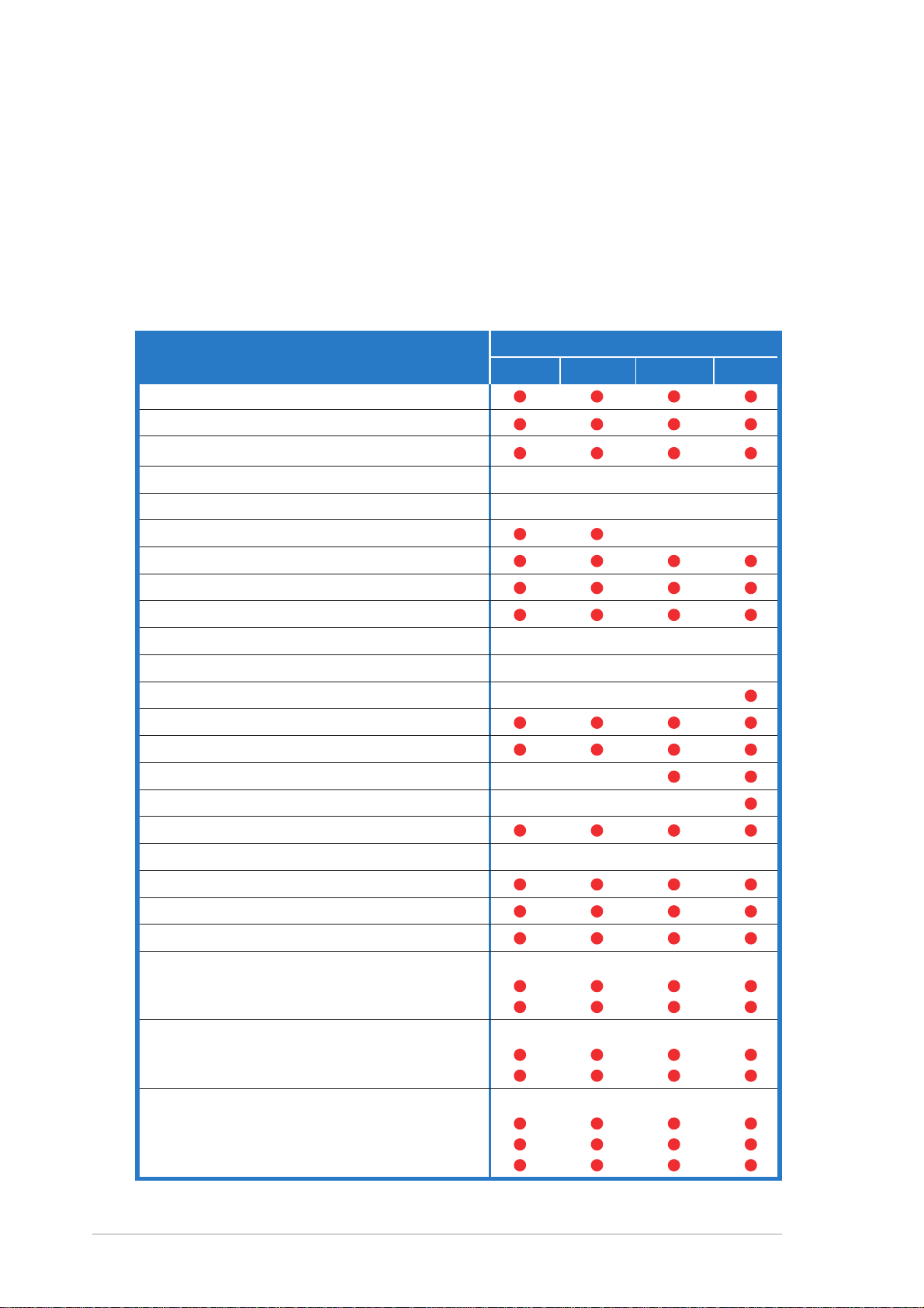
1.1 System package contents
Check your ASUS AP1720-E2 package with the items on the following
table. The package contents vary for the following configurations:
• AS8 (eight hot-swap SCSI hard disk drives)
• AS4 (four hot-swap SCSI hard disk drives)
• AA4(four hot-swap SATA hard disk drives)
• AI4 (four internal SATA/IDE hard disk drives)
Item Description
ASUS AK25 5U rackmount chassis with:
• ASUS NCCH-DL motherboard
• 600 W single or redundant power supply*
• SATA backplane board
• SCSI backplane board
• ASUS U320 SCSI card and cable
• 52x CD-ROM drive
• Floppy disk drive
• Chassis fan
• HDD fan
• Hot-swap HDD trays (including HDD screws)
• Internal HDD rails (4 pairs)
• Chassis roller wheels (1 set)
• Front I/O board
• SATA signal cable (4 sets)
Configurations
AS8 AS4 AA4 AI4
11
1
11
22
2
22
22
2
22
88
8
88
11
1
11
11
1
11
44
4
44
11
1
11
44
4
44
• SATA power cable
• SMBus cable
• Dummy covers (4 pieces)
AC power cable
System screws and cables
System keys ( 2 pcs.)
Bundled CDs
• AP1720-E2 support CD with ASWM**
• TrendMicro® ServerProtect® CD
Documentation
• ASUS AP1720-E2 user guide
• ASUS NCCH-DL user guide
Optional items
• ASUS AK25 rackmount rail kit
• ASUS AK25 internal HDD cage (non-hot swap)
• ASUS AK25 600 W 2+1 redundant power supply
* All models support a 600 W single or redundant power supply.
** ASUS System Web-based Management
44
4
44
44
4
44
88
8
88
1-2
Chapter 1: Product introduction
Page 13
1.2 System specifications
The ASUS AP1720-E2 is a barebone server system featuring the ASUS
NCCH-DL motherboard. The server supports dual Intel® Xeon™
processors in 604-pin sockets, and includes the latest technologies
through the chipsets embedded on the motherboard.
Chassis Pedestal or rackmount 5U with removable front door bezel and
chassis foot stand or roller-wheels.
System dimension 431 mm (H) x 220 mm (W) x 510 mm (D)
Motherboard ASUS NCCH-DL (ATX form factor: 12 in x 9.8 in)*
®
Chipset Intel
Processor Socket 604 for Intel
Memory 4 x 184-pin DDR sockets for up to 4GB memory
E82875P Memory Controller Hub (MCH)
Intel® 6300ESB I/O Controller Hub (ICH)
®
Xeon™ Nocona/Prestonia CPU with
800/533MHz FSB and on-die 1MB/512KB L2 cache with full speed
Supports PC3200/2700/2100 unbuffered ECC or
non-ECC DDR DIMMs
LAN Intel® 82547GI Gigabit LAN controller(CSA)
®
RAID Promise
(supports RAID 0/RAID 1/RAID 0+1/Multi-RAID)
Expansion slots 1 x AGP Pro/8X slot
2 x 64-bit/66Mhz 3.3V PCI-X slots**
2 x 32-bit/33Mhz 5V PCI slots
Drive bays 1 x 3.25-inch FDD bay
3 x 5.25-inch drive bays
Front I/O 1 x IEEE 1394 port
1 x Headphone port
1 x Microphone port
Rear panel I/O 1 x Parallel port
2 x Serial ports
1 x LAN (RJ-45) port
4 x USB 2.0 ports
1 x IEEE 1394 port
1 x PS/2 keyboard port
1 x PS/2 mouse port
Line In / Line Out / Microphone ports
PDC20319 controller
Management ASUS Server Web-based Management (ASWM) 2.0
Hardware monitors Voltage, temperature, and fan speed monitoring
Automatic System Restart (ASR) feature
Power supply 600 W power supply
600 W redundant power supply
* Refer to Chapter 4 “Motherboard information” for information on the internal connectors.
** In AS8/AS4 models, the ASUS U160/U320 SCSI card occupies one 64-bit PCI-X slot.
(with 24-pin and 8-pin power plugs)
(optional)
or
ASUS AP1720-E2 barebone server
1-3
Page 14
1.3 Front panel features
The AP1720-E2 chassis displays a stylish front bezel with lock. The bezel
covers the system components on the front panel and serves as security.
Open the bezel to access the front panel components.
The drive bays, power and reset
buttons, LED indicators, CD-ROM
drive, floppy drive, IEEE 1394 and
front panel audio ports are located on
the front panel. For future installation
of 5.25-inch devices, two drive bays
are available.
Drive bays
CD-ROM drive
Empty 5.25-inch bays
Power button
Reset button
Message LED
HDD access LED
Power LED
Floppy disk drive
IEEE 1394 port
Microphone port
Headphone port
1-4
Security lock
Chapter 1: Product introduction
Page 15
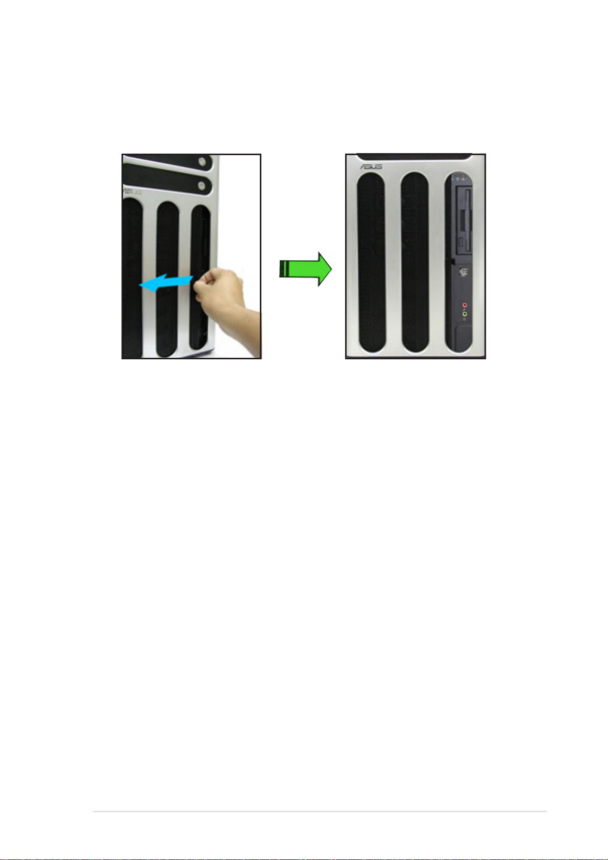
If you wish to access front I/O ports and floppy disk drive without opening
the bezel, hold the tab and move the sliding panel (rightmost panel) to the
left as shown.
ASUS AP1720-E2 barebone server
1-5
Page 16
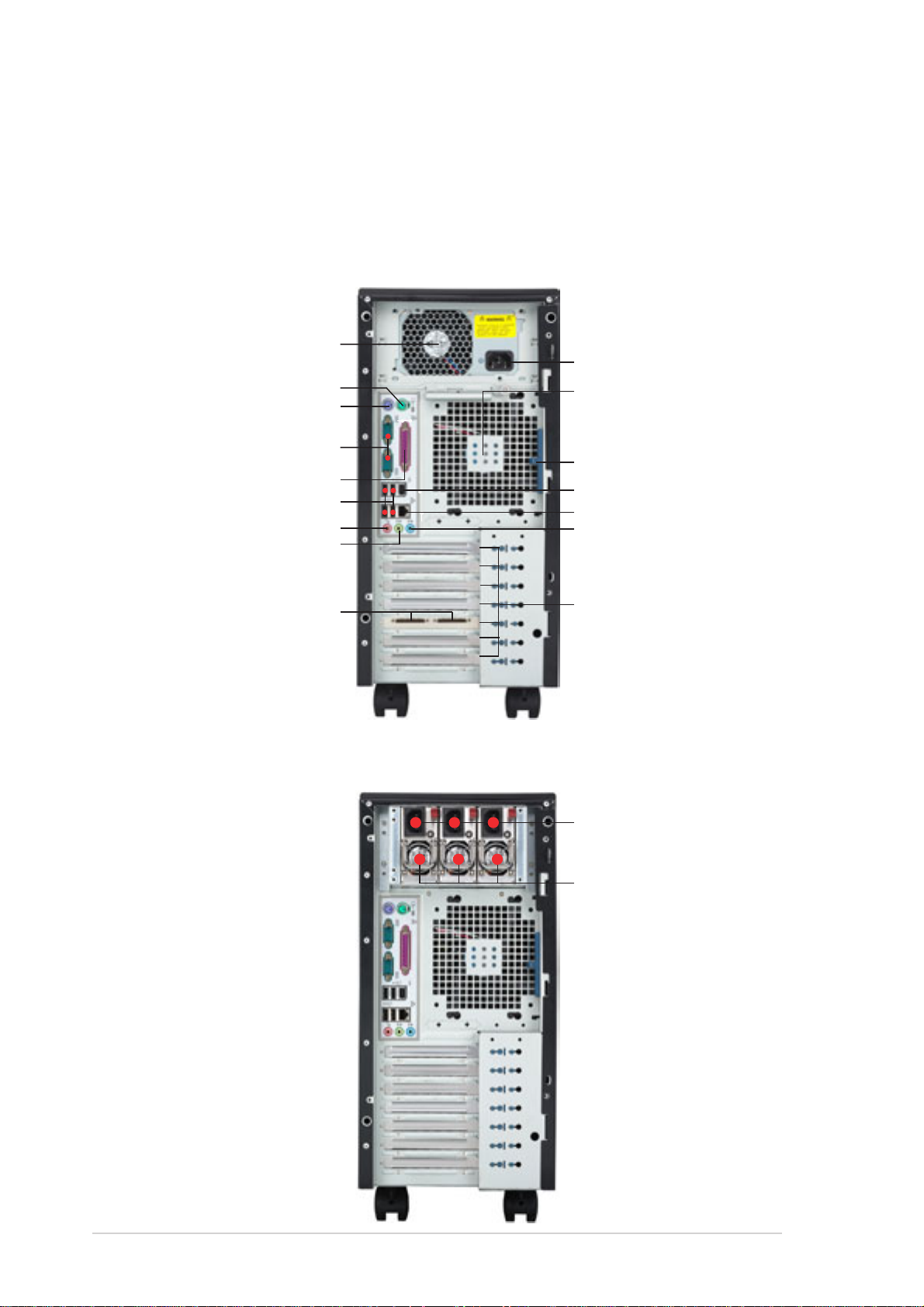
1.4 Rear panel features
The rear panel includes a slot for the motherboard rear I/O ports,
expansion slots, a chassis lock and intrusion switch, a vent for the system
fan, and power supply module.
Single power supply models
Power supply module
Power connector
PS/2 mouse port
PS/2 keyboard port
12 cm system fan
Serial ports
Parallel port
USB ports
Microphone port
Line Out port
SCSI connectors*
* On AS8/AS4
configuration only.
Chassis cover lock
IEEE 1394 port
Gigabit LAN port
Line In port
Expansion slots
Redundant power supply models
Power connectors
300 W power supply
modules**
1-6
** The system comes
with two power supply
module. The third
power supply module
for redundant power is
optional.
Chapter 1: Product introduction
Page 17
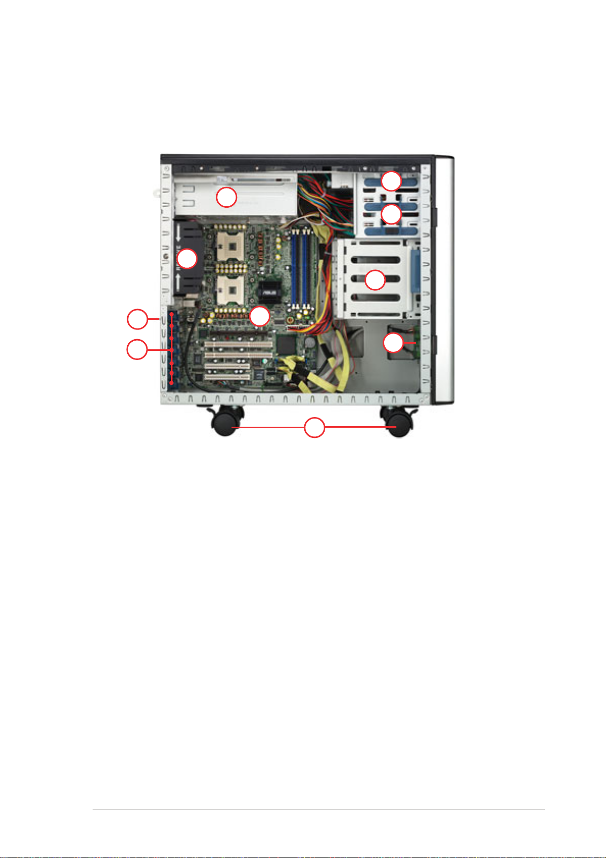
1.5 Internal features
The barebone server system includes the basic components as shown.
AI4 (four internal IDE/SATA configuration)
2
1
3
5
4
10
6
1. Power supply cage
2. CD-ROM drive
3. 2 x 5.25-inch drive bays
4. Hard disk drive cage
5. Chassis fan
7
9
8
6. Expansion card locks
7. NCCH-DL motherboard
8. Chassis roller wheels
9. Front I/O board
10.Chassis intrusion switch
ASUS AP1720-E2 barebone server
1-7
Page 18
AA4 (four hot-swap SATA configuration)
1
5
2
3
11
8
10
6
12
7
AS4 (four hot-swap SCSI configuration)
4
9
1-8
14
13
11
Chapter 1: Product introduction
Page 19
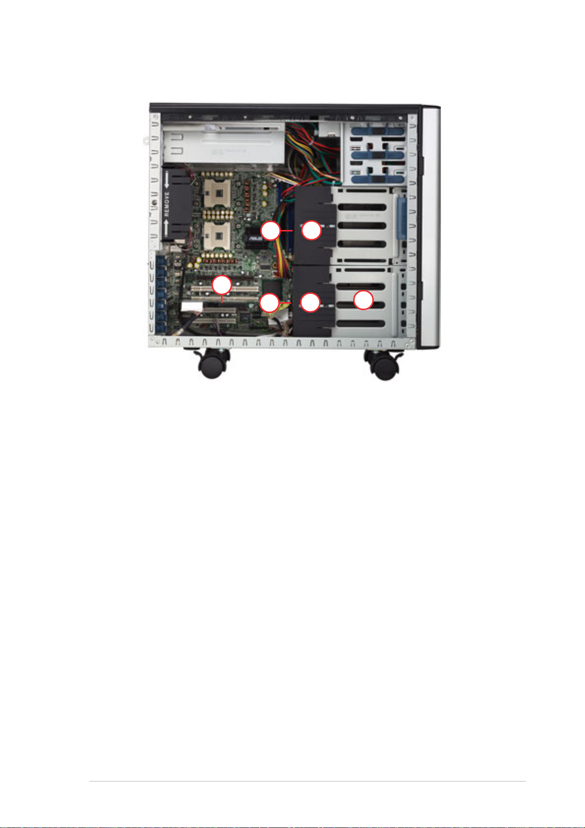
AS8 (eight hot-swap SCSI configuration)
14
1. Power supply cage
2. CD-ROM drive
3. 2 x 5.25-inch drive bays
4. Hard disk drive cage
5. Chassis fan
13
15
11
16
10.Chassis intrusion switch
11. HDD fan
12.SATA backplane (hidden)
13.SCSI backplane (hidden)
14.ASUS U160/U320 SCSI card
17
6. Expansion card locks
7. NCCH-DL motherboard
8. Chassis roller wheels
9. Front I/O board
ASUS AP1720-E2 barebone server
15. Second SCSI backplane (hidden)
16.Second HDD fan
17.Second hard disk drive cage
1-9
Page 20
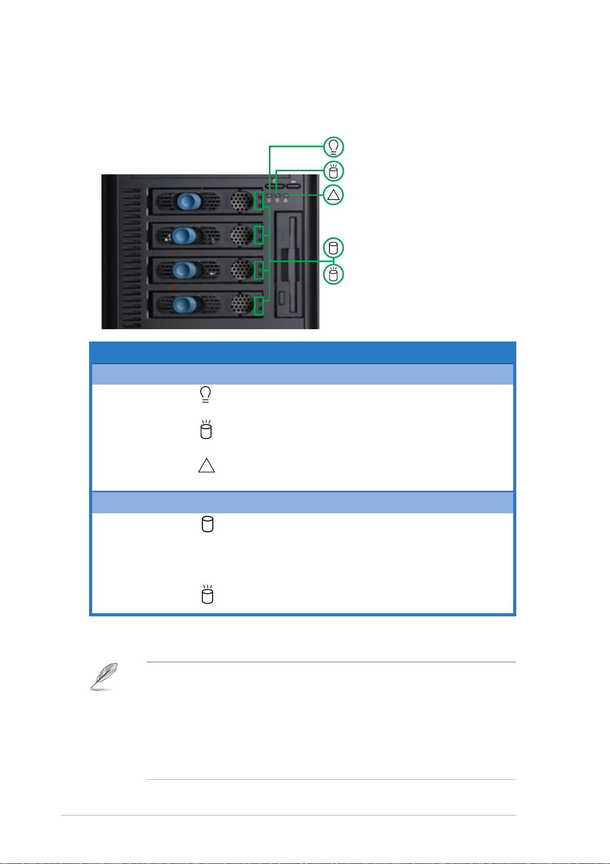
1.6 LED information
The barebone system comes with five LED indicators. Refer to the
following table for the LED status description.
Power LED (blue)
HDD Access LED (green)
!
Message LED (red)
Drive Status LED (green/red)
Drive Activity LED (green)
LED Icon Display status Description
System
Power LED ON System power ON
Blinking System is in suspend mode
HDD Access LED OFF No activity
Blinking Read/write data into the HDD
Message LED OFF System is normal; no incoming event
Hard disk drives
Drive Status LED Green Installed HDD is in good condition
Drive Activity LED Blinking Read/write data into the HDD
* For SCSI models only (AS8/AS4)
** SCSI Access Fault-Tolerant Enclosure (on AS8/AS4 models only)
!
Blinking ASMS indicates a HW monitor event
Red HDD failure
Red and Green HDD rebuilding using the RAID card
blinking alternately* SAF-TE** function
1-10
• The Power, HDD Access, and Message LEDs are visible even if
the system front bezel is closed.
• For AA4 configuration:
1. The Drive Activity LEDs do not light up
2. The Drive Status LEDs only light up green to indicate that the
installed Serial ATA HDD is in good condition.
Chapter 1: Product introduction
Page 21

Chapter 2
This chapter lists the hardware setup
procedures that you have to perform when
installing or removing system components.
ASUS AP1720-E2 barebone server
Hardware setup
2-1
Page 22
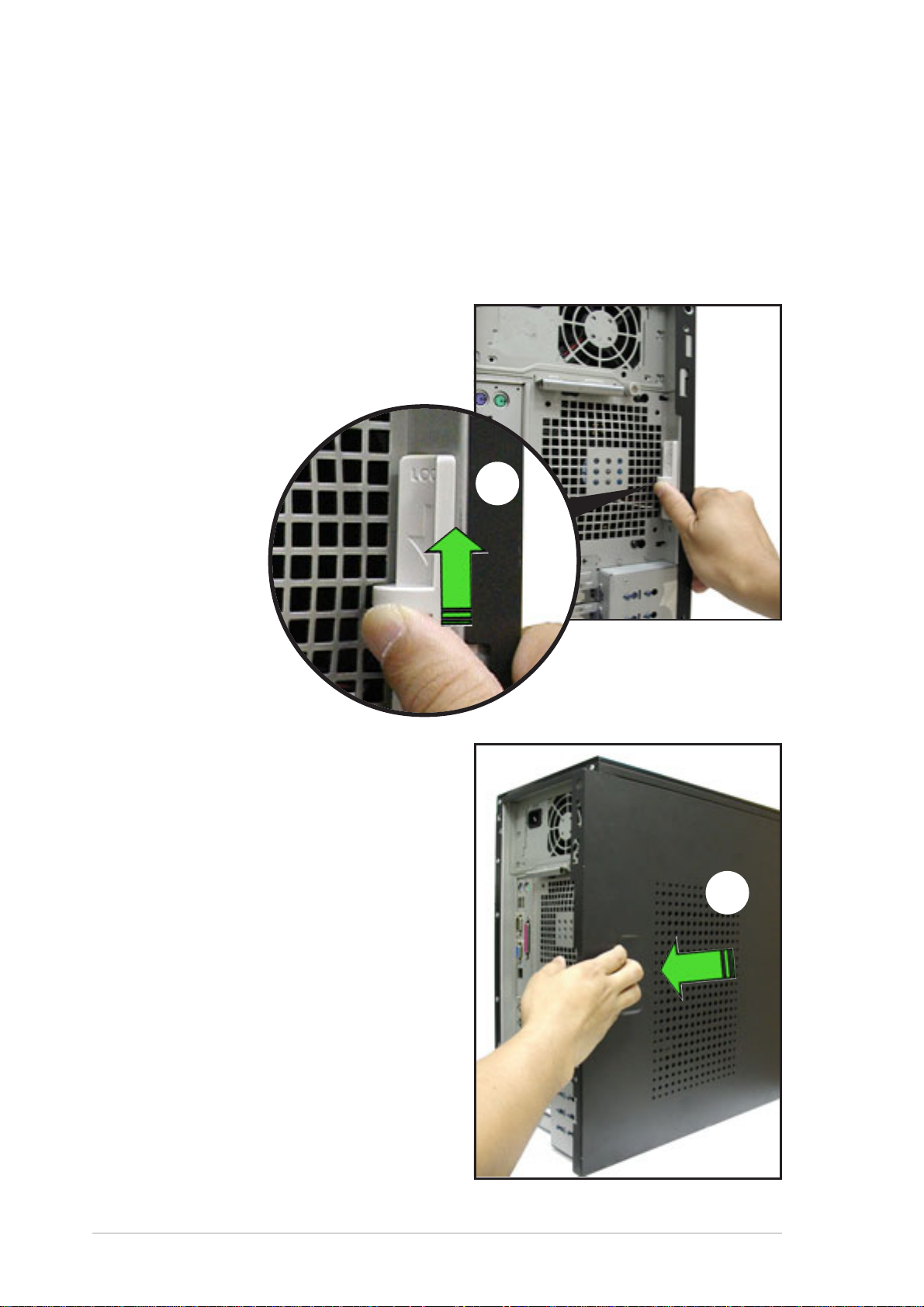
2.1 Chassis cover
The chassis features a “screwless design” that allows convenient
assembly and disassembly. You can simply push or slide mechanical bolts
and locks to remove the cover.
2.1.1 Removing the side cover
1. Push up the chassis lock on the
rear panel to release the side
cover.
1
2. Slide the side cover for about half
an inch toward the rear until it is
disengaged from the chassis.
2
2-2
Chapter 2: Hardware setup
Page 23
Viewing the internal structure
Without the side cover, the internal structure and installed components of
the barebone server vary depending on the model you purchased. Refer
to section “1.5 Internal features” for the different model configurations.
Perform the procedures in the succeeding sections to install the CPU,
system memory, disk drives, and expansion cards; replace fans and power
supply; and connect the system cables.
You may need to remove some of the installed components to access
the DIMM sockets and internal connectors. Refer to section “2.10
Removable components” for instructions.
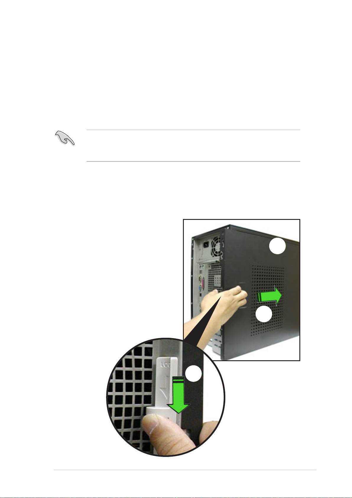
2.1.2 Re-installing the side cover
To re-install the side cover:
1. Match and insert the hooks of the
cover to the elongated holes on
the side of the chassis. All the six
hooks (three each on the top and
bottom) of the cover must
properly fit the designated holes.
2. Slide the cover toward the front
until it snaps in place.
3. Push down the chassis lock to
secure the side cover.
1
2
3
3
ASUS AP1720-E2 barebone server
2-3
Page 24
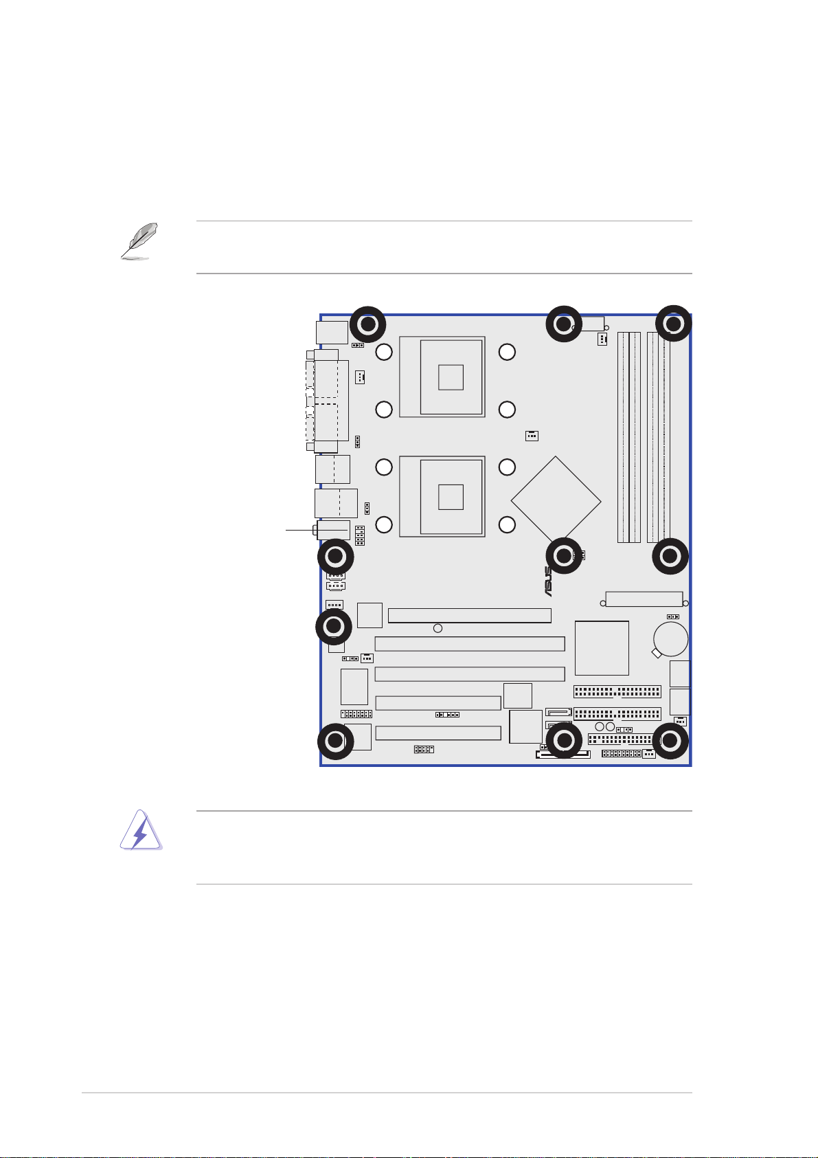
2.2 Motherboard information
®
The barebone server comes with the ASUS NCCH-DL motherboard
already installed. The motherboard is secured to the chassis by ten (10)
screws as indicated by circles in the illustration below.
Refer to “Chapter 4 Motherboard information” for detailed information
on the motherboard.
This side towards
the rear of the chassis
Make sure to unplug the power cord before installing or removing any
motherboard component or connection. Failure to do so may cause
you physical injury and may damage motherboard components.
NCCH-DL
2-4
Chapter 2: Hardware setup
Page 25
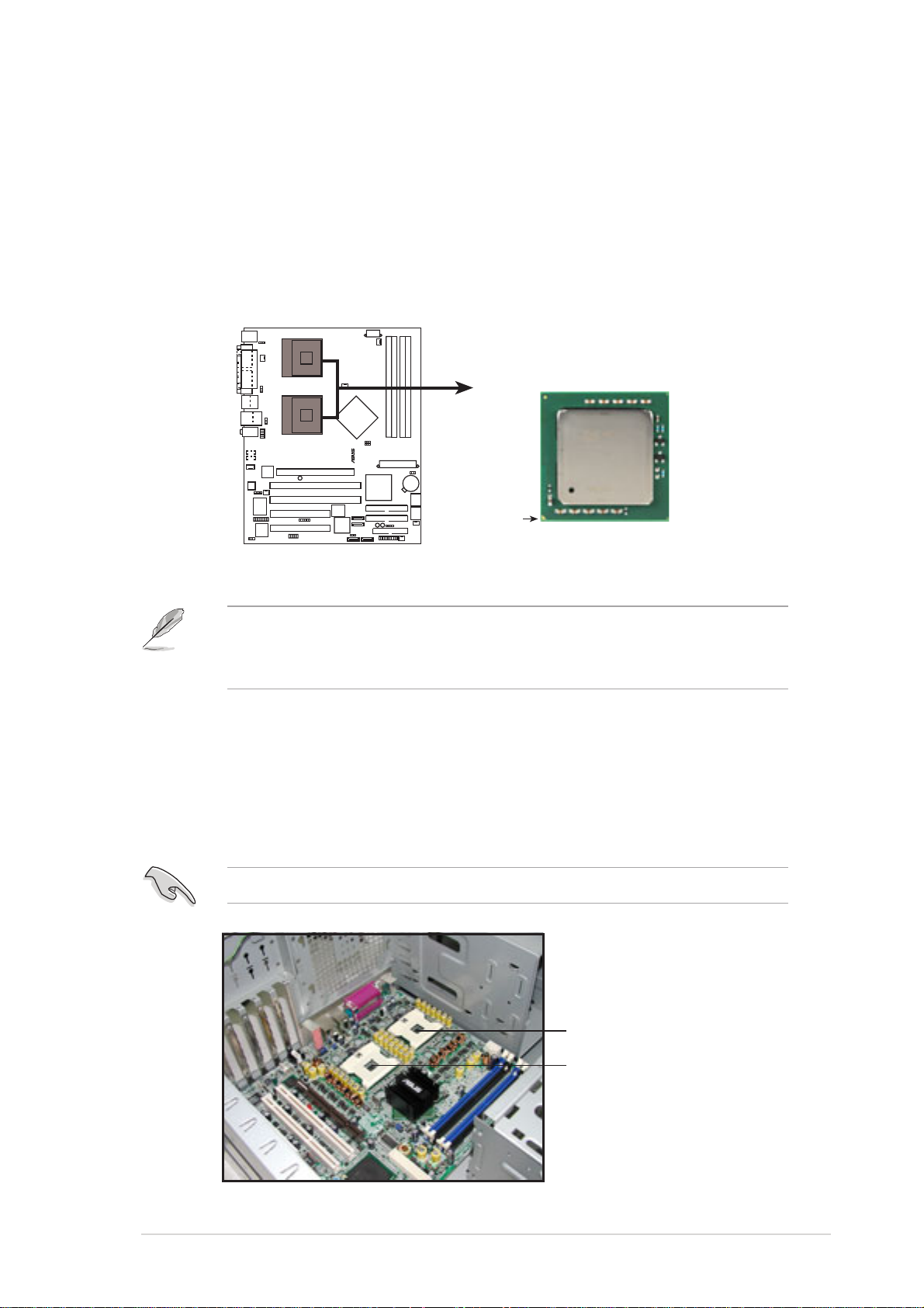
2.3 Central Processing Unit (CPU)
®
2.3.1 Overview
The motherboard comes with dual surface mount 604-pin Zero Insertion
Force (ZIF) sockets. The sockets are designed for the Intel® Xeon™
Processor in the 604-pin package.
Intel Xeon
NCCH-DL
Gold Arrow
NCCH-DL Socket 604
Before installing the CPU, remove the chassis fan attached to the inner
side of the rear panel to allow enough space for the installation. Refer
to section “2.10 Removable components” for details.
2.3.2 Installing the CPU
Note in the above illustration that the CPU has a gold triangular mark on
one corner. This mark indicates the processor Pin 1 that should match a
specific corner of the CPU socket.
If installing only one CPU, use the socket CPU1.
Socket for CPU1
Socket for CPU2
ASUS AP1720-E2 barebone server
2-5
Page 26
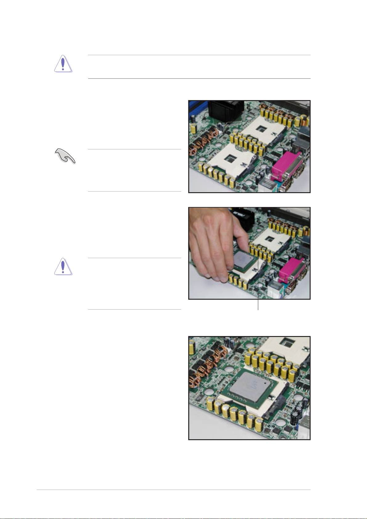
Incorrect installation of the CPU into the socket may bend the pins and
severely damage the CPU!
Follow these steps to install a CPU.
1. Locate the 604-pin ZIF sockets
on the motherboard. Flip up the
socket lever and push it all the
way to the other side.
Make sure that the socket
lever is pushed back all the
way, otherwise the CPU
does not fit in completely.
2. Position the CPU above the
socket as shown.
3. Carefully insert the CPU into the
socket until it fits in place.
The CPU fits only in one
correct orientation. DO NOT
force the CPU into the socket
to prevent bending the pins
and damaging the CPU!
4. Carefully push down the socket
lever to secure the CPU. The
lever clicks on the side tab to
indicate that it is locked.
5. Apply the thermal interface
material (thermal grease) to the
top of the CPU. This thermal
grease should come with the
CPU package.
6. Repeat steps 1 to 5 if you wish to
install a second CPU.
Marked corner
(gold arrow)
2-6
Chapter 2: Hardware setup
Page 27
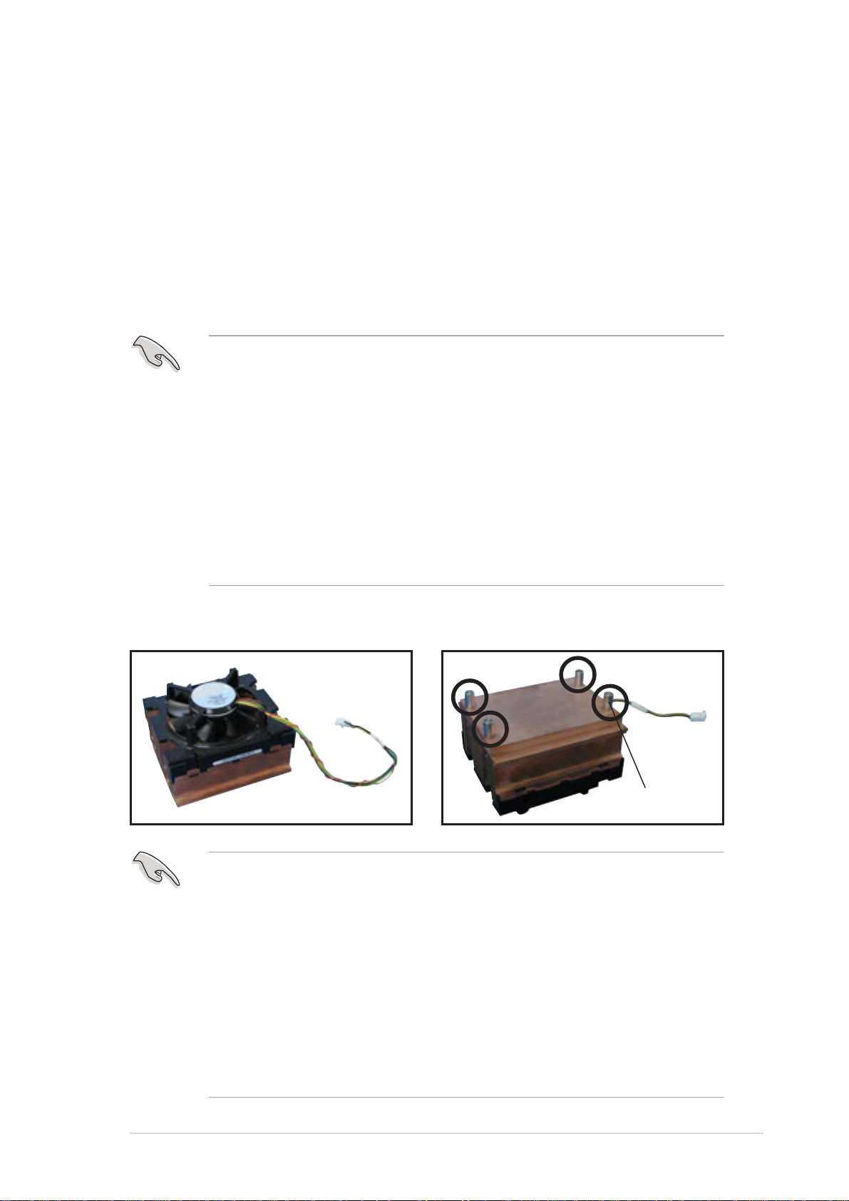
2.3.3 Installing the CPU heatsink and fan
The Intel® Xeon™ processors require an Intel® certified heatsink and fan
assembly to ensure optimum thermal condition and performance.
When you buy a boxed Intel
®
CPU, the package includes the heatsink, fan,
retention brackets, screws, thermal grease, installation manual, and other
items that are necessary for CPU and CPU heatsink and fan installation.
Important notes
• This system does not support Intel® Xeon™ FSB 533 box fan and
heatsink assembly. When installing Intel® Xeon™ FSB 533 CPU(s),
it is recommended that you use Nocona-compatible fan and
heatsink assembly. Visit the ASUS website for details and a list of
CPU fan and heatsink assembly qualified for use on this system.
®
• When installing Intel
recommended that you use the fan and heatsink assembly (ies)
included in the CPU package(s).
• Refer to the installation manual that came with the CPU package
for details on fan and heatsink assembly installation.
Xeon™ FSB 800 boxed CPU(s), it is
CPU heatsink (top view) CPU heatsink (bottom view)
Before installing the CPU heatsinks:
• Make sure that you have applied the thermal grease on top of the
CPU before installing the fan and heatsink assembly.
• Ensure that the jumpers FM_CPU1 and FM_CPU2 are set
correctly depending on the pin definition of your CPU fan cables.
Refer to the motherboard user guide for information.
• Remove the chassis fan to have more space for the CPU fan and
heatsink assembly installation. Refer to section “2.10 Removable
components” for details.
ASUS AP1720-E2 barebone server
Heatsink screw
2-7
Page 28
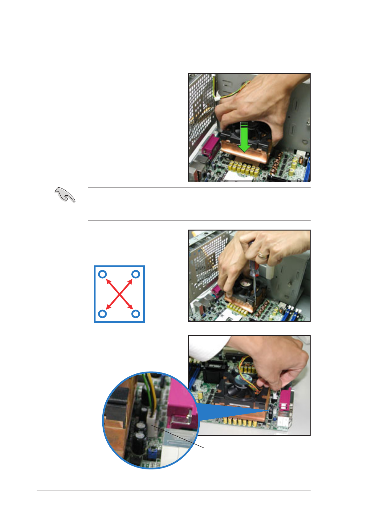
To install the CPU heatsink and fan:
1. Place the heatsink on top of the
installed CPU, making sure that
the four screws on the heatsink
align with the screw holes on the
CEK spring.
The CEK springs come pre-installed under the CPU sockets to support
the weight of the CPU heatsinks. It is recommended that you keep the
springs installed to prevent motherboard breakage.
2. Use a Phillips screwdriver to
tighten the four heatsink screws
in a diagonal sequence.
4
1
2
3
3. Connect the fan cable to the 4-pin
connector labeled CPU_FAN1.
CPU1 fan connector
(CPU_FAN1)
2-8
Chapter 2: Hardware setup
Page 29
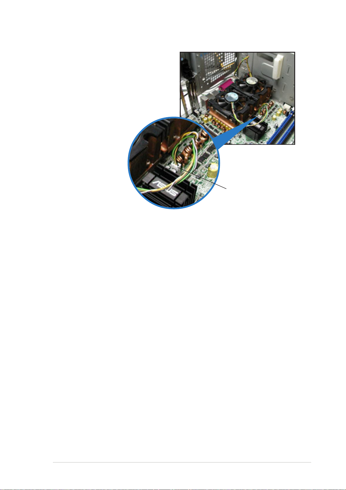
4. Repeat steps 1 to 3 to install the
other heatsink if you have
installed a second CPU, then
connect the fan cable to the 4-pin
connector labeled CPU_FAN2.
The heatsinks appear as shown
when installed.
CPU2 fan connector
(CPU_FAN2)
ASUS AP1720-E2 barebone server
2-9
Page 30
2.4 System memory
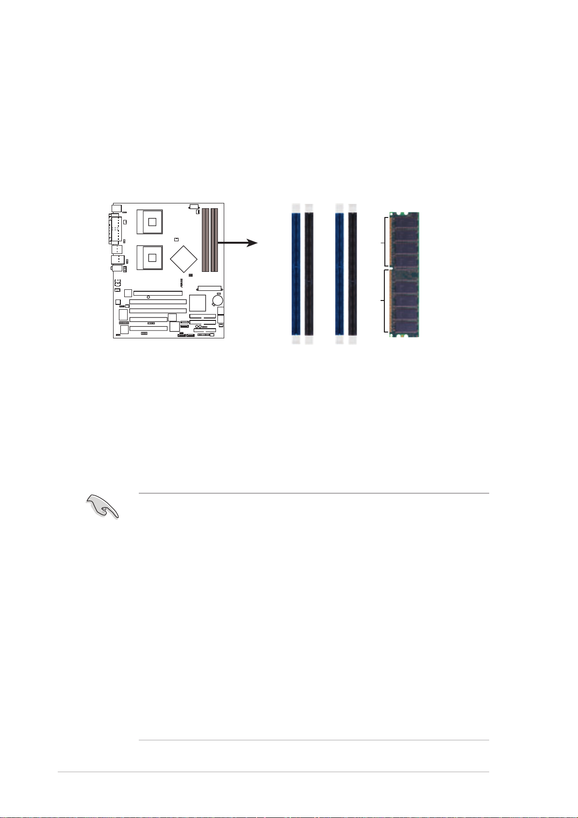
®
1
1
2
2.4.1 Overview
The motherboard comes with four Double Data Rate (DDR) Dual Inline
Memory Module (DIMM) sockets.
The following figure illustrates the location of the DDR DIMM sockets.
DIMM_A
NCCH-DL
NCCH-DL 184-pin DDR DIMM sockets
DIMM_A2DIMM_B
DIMM_B
80 Pins104 Pins
2.4.2 Memory configurations
You may install unbuffered ECC or non-ECC 64MB, 128MB, 256MB,
512MB, and 1GB DDR DIMMs into the DIMM sockets using the
recommended memory configurations.
Important notes
1. Installing DDR DIMMs other than the recommended configurations
may cause memory sizing error or system boot failure. Use any of
the recommended configurations in Table 1.
2. In dual-channel configurations, install only identical (the same
type and size) DDR DIMM pairs for each channel.
3. Always install DIMMs with the same CAS latency. For optimum
compatibility, it is recommended that you obtain memory modules
from the same vendor.
4. Make sure that the memory frequency matches the CPU FSB
(Front Side Bus). Refer to Table 2.
5. DIMMs installed into any three sockets will function in single-
channel mode.
6. When all four sockets are populated with 1GB DIMMs (total 4GB),
the system may detect only about 3.6+ GB (less than 4 GB) due to
resource allocation on onboard devices.
2-10
Chapter 2: Hardware setup
Page 31

Table 1 Recommended memory configurations
Sockets
Mode DIMM_A1 DIMM_A2 DIMM_B1 DIMM_B2
(blue)(black)(blue)(black)
Single-channel (1) Populated — — —
(2) — Populated — —
(3) — — Populated —
(4) — — — Populated
Dual-channel (1) Populated
(2) —
(3)* Populated Populated Populated Populated
*
For dual-channel configuration (3), you may:
— Populated —
Populated — Populated
• install identical DIMMs in all four sockets, or
• install identical DIMM pair in DIMM_A1 and DIMM_B1 (blue
sockets) and identical DIMM pair in DIMM_A2 and DIMM_B2
(black sockets)
Table 2 Memory frequency/CPU FSB synchronization
CPU FSB DDR DIMM Type Memory Frequency
800 MHz PC3200 400 MHz
533 MHz PC2700 333 MHz
400 MHz PC2100 266 MHz
Obtain DDR DIMMs only from ASUS qualified vendors for better
system performance. Visit the ASUS website (www.asus.com) for the
latest QVL.
ASUS AP1720-E2 barebone server
2-11
Page 32

2.4.2 Installing a DIMM
Make sure to unplug the power supply before adding or removing
DIMMs or other system components. Failure to do so may cause
damage to both the motherboard and the components.
Follow these steps to install a DIMM.
To access the DIMM sockets, you may need to remove the HDD fan.
Refer to section “2.10 Removable components” for instructions.
1. Unlock a DIMM socket by
pressing the retaining clips
outward.
2. Align a DIMM on the socket such
that the notch on the DIMM
matches the break on the socket.
Unlocked Retaining Clip
3. Firmly insert the DIMM into the
socket until the retaining clips
snap back in place and the DIMM
is properly seated.
DDR DIMM notch
2.4.3 Removing a DIMM
Follow these steps to remove a DIMM.
1. While supporting the DIMM with
your fingers, press the retaining
clips outward simultaneously to
release the DIMM from the socket.
2. Remove the DIMM from the
socket.
2-12
Locked Retaining Clip
Chapter 2: Hardware setup
Page 33

2.5 Front panel assembly
2.5.1 Removing the front panel assembly
Before you can install a 5.25-inch drive, you should first remove the
front panel assembly (front bezel and front panel cover). The front
panel assembly is attached to the chassis through four hooked tabs
on the left side and four hinge-like tabs on the right side.
To remove the front panel assembly:
1. Pull the lock lever (blue bar) on the front
edge of the chassis outward to release
the front panel assembly.
Lock lever
2. Pull and swing the left edge of the front
panel outward.
ASUS AP1720-E2 barebone server
2-13
Page 34

3. Unhook the hinge-like tabs from the holes on the right side of the front
panel to completely detach the front panel assembly from the chassis.
Do not use too much force when removing the front panel assembly.
Hinge-like tab
2-14
Chapter 2: Hardware setup
Page 35

2.5.2 Re-installing the front panel assembly
To re-install the front panel assembly (front bezel and front panel cover):
1. Insert the four hinge-like tabs to the holes on the right edge of the
chassis.
2. Swing the front panel to the left and fit the four (4) hooked tabs to the
left side of the chassis until the tabs snap back in place.
1
Hinge-like tab
2
Hooked tab
ASUS AP1720-E2 barebone server
2-15
Page 36

2.6 5.25-inch drives
If you have previously used and powered up the system, and that it
may be connected to an AC power source, make sure to unplug the
power cable before installing or removing any system components.
Failure to do so may cause damage to the motherboard and other
system components!
Three 5.25-inch drive bays are
located on the upper front part of the
chassis. A CD-ROM drive that comes
standard with the system package
occupies the uppermost bay
(labeled 1)
(labeled 2 and 3)
additional 5.25-inch devices.
. The two lower bays
are available for
1
2
3
To install a 5.25-inch drive:
1. Use a Phillips (cross) screwdriver
to remove the screws that secure
the metal cover of the bay where
you wish to install the drive.
2. From the side of the drive bay,
slide the drive bay lock by
pushing it to the left to release the
drive lock bar.
Drive lock bar
2-16
Drive bay lock
Chapter 2: Hardware setup
Page 37

3. When released, pull up the drive bay lock bar. Underneath the lock bar
are two pegs that match the holes on the drive bay. This mechanism
secures the drive to the bay in place of screws.
Lock pegs
Drive bay holes
4. While holding up the drive lock
bar, carefully insert a 5.25-inch
drive into the bay, until the back of
the drive aligns to the rear edge
of the drive cage.
Due to space constraints inside the chassis, do not insert the drive all
the way at this time. This will allow you enough space to easily connect
the drive cables.
5. Connect the IDE cable to the IDE
connector on the back of the
drive.
6. Connect a 4-pin plug from the
power supply to the power
connector on the back of the
drive.
IDE cable
ASUS AP1720-E2 barebone server
Power plug
2-17
Page 38

7. Make sure that the drive and bay
holes align as shown. When in
place, the drive protrudes about
an inch from the front panel.
8. Pull down the bar lock and insert
the lock pegs to the drive/bay
holes, then push the drive lock
to the right to secure the drive.
9. On the front panel assembly, detach the plastic bay cover opposite the
5.25-inch drive that you installed by pressing the two hooked tabs on
each side of the bay cover.
10.Re-install the front panel assembly when done. Refer to section “2.5.2
Re-installing the front panel assembly” for instructions.
2-18
Chapter 2: Hardware setup
Page 39

2.7 Hard disk drives
2.7.1 Installing a hot-swap SATA/SCSI
hard disk drive
If you purchased an AS8, AS4, or AA4 configured model, follow these
instructions to install a hot-swap SATA or SCSI hard disk drive (HDD).
1. Open the front bezel to access the hot-swap drive trays.
2. Release a drive tray by pushing
the spring lock to the right, then
pulling the tray lever outward. The
drive tray ejects slightly after you
pull out the lever.
3. Firmly hold the tray lever and pull
the drive tray out of the bay.
Tray leverSpring lock
4. An empty drive tray requires a metal bracket for support. Use a Phillips
(cross) screwdriver to remove the bracket when you are ready to install
a hard disk in the drive tray.
Metal bracket
ASUS AP1720-E2 barebone server
2-19
Page 40

5. Place a SATA or an SCA SCSI
hard disk to the drive tray, and
secure it with four screws.
6. Carefully insert drive tray and
push it all the way to the depth of
the bay until just a small fraction
of the tray edge protrudes.
7. Push the tray lever until it clicks,
and secures the drive tray in
place. The drive tray is correctly
placed when its front edge aligns
with the bay edge.
2-20
Chapter 2: Hardware setup
Page 41

2.7.2 Installing an internal IDE/SATA HDD
If you purchased an internal IDE/SATA model (AI4), your package comes
with specially designed hard disk drive rails. Depending on which bay you
wish to install your hard disk drive, the orientation of the drive rails vary so
that the screw holes match those on the drive.
For identification purposes, the drive rails are referred to as “Rail 1” and
“Rail 2” as shown below.
Rail 1
Rail handle Hole 1 Hole 2 Hole 3
Rail 2
Take note of the correct orientation of the drive rails. There is only one
correct way to attach the rails when installing drives on the hard disk
drive cage.
Hole 4
Installing an IDE hard disk drive to the first hard disk drive cage
To install an IDE hard disk drive to the first hard disk drive cage:
1. Remove the front panel assembly. Refer to section 2.5.1 for
instructions.
2. Use a Phillips (cross) screwdriver to attach Rail 1 to the side of the
drive as shown. The rail end should be on the side of the drive
connectors.
Drive connectors
Hole 1 Hole 3
ASUS AP1720-E2 barebone server
Rail handle
2-21
Page 42

3. Attach Rail 2 to the other side of the drive as shown. The rail end
should be on the side of the drive connectors.
Rail handle
Hole 1 Hole 3
4. Check the HDD jumper setting.
Refer to the label pasted on the
HDD for the description of
jumper settings. The setting
“Cable Select” is recommended.
5. Carefully insert the drive into a
bay on the front panel.
6. Push the drive all the way to the
depth of the bay until the rail
locks clicks, indicating that the
drive is securely in place.
Drive connectors
7. Connect the IDE and power
cables to their corresponding
connectors on the back of the
drive.
8. Follow steps 2 to 6 if you wish to
install other hard disk drives.
9. Re-install the front panel
assembly when done.
2-22
Chapter 2: Hardware setup
Page 43

Installing a Serial ATA HDD to the first hard disk drive cage
To install a Serial ATA hard disk drive to the first hard disk drive cage:
1. Follow instructions 1 to 6 of the previous section.
2. Connect the 15-pin SATA power
plug to the power connector at
the back of the drive.
3. Connect the other end of the
SATA power cable to a 4-pin plug
(female) from the power supply
unit.
4. Connect one end of the supplied
7-pin SATA cable to the SATA
connector at the back of the
drive, then connect the other end
to a SATA connector on the
motherboard. Refer to the
motherboard user guide for the
location of the SATA connectors.
ASUS AP1720-E2 barebone server
2-23
Page 44

Installing an IDE/SATA HDD to the internal HDD cage
Follow these instructions to install an IDE or Serial ATA hard disk drive to
the optional internal hard disk drive cage (non-swap).
1. Install the internal HDD cage following the instructions on Chapter 3
“Installation options”.
2. Follow steps 1 of 4 of the section “Installing an IDE hard disk drive to
the first hard disk drive cage”.
3. Carefully insert the drive into a
bay on the second drive cage as
shown.
4. Connect the signal and power
cables to their corresponding
connectors on the back of the
drive. Refer to the preceding
sections for details.
5. Follow steps 2 to 4 if you wish to
install additional hard disk drives.
6. Re-install the side cover when
done. Refer to section “2.1.2
Installing the side cover.”
2-24
Chapter 2: Hardware setup
Page 45

Installing an HDD dummy cover
The HDD dummy covers come pre-installed on the front panel bezel. In
case you removed the covers, follow these steps to re-install them.
To install an HDD dummy cover:
1. From the inside of the front panel
assembly, insert the flat end of a
dummy cover into the slot as
shown. The end with the hook tab
should be close to the front panel
LEDs.
Flat end
2. Press the dummy cover into the
slot opening until the hook tab
clicks in place.
Hook tab
3. When installed, the dummy cover
appears as shown.
ASUS AP1720-E2 barebone server
2-25
Page 46

2.8 Expansion cards
The chassis is designed with a screwless expansion slot frame on the rear
panel. This design feature allows you to install or remove an expansion
card in less steps.
Make sure to unplug the power cord before installing or removing
expansion cards. Failure to do so may cause physical injury, and
damage to the card and motheboard components!
2.8.1 Installing a standard size expansion card
To install a standard size expansion card:
1. Remove the plastic card lock opposite the slot where you wish to install
the expansion card. Release the card lock by pressing the center tabs
and pushing outward. Set the card lock aside for later use.
Card lock tab
2. Carefully install an expansion
card making sure that it is
properly seated on the slot.
2-26
Chapter 2: Hardware setup
Page 47

3. When the card is in place, secure
it with the plastic card lock that
you removed earlier.
Card lock tab
ASUS AP1720-E2 barebone server
2-27
Page 48

2.8.2 Installing a long expansion card
If you wish to install a long expansion card, such as some types of RAID
cards, you need to remove the lower hot swap drive cage (for AS8 models
or separately purchased second hot-swap HDD cage) and install an
internal (non-hot swap) drive cage with long card guides that keep the
expansion cards firmly seated on the slots.
1. The internal drive cage is optional and separately purchased. See
section “Chapter 3: Installation options” for instructions on installing
the drive cage.
2. The AS4, AA4, and AI4 models support long expansion cards.
To install a long expansion card:
1. Remove the plastic card lock opposite the slot where you wish to install
the expansion card. Release the card lock by pressing the center tabs
and pushing outward. Set the card lock aside for later use.
2. Tilt the long card as shown while
aligning the metal bracket with
the slot opening on the rear
panel.
3. When the card is inside the
chassis, push down the end of
the card until it is level with the
PCI slot.
4. Push the card connector into the
PCI slot until it is securely seated.
5. When the card is in place, secure
it with the plastic card lock that
you removed earlier.
2-28
Chapter 2: Hardware setup
Page 49

2.8.3 Removing an expansion card
To remove an expansion card:
1. Remove the plastic card lock that secures the expansion card.
Card lock tab
2. Firmly hold the expansion card
and pull it out of the slot.
3. Place the plastic card lock back
where you removed it.
ASUS AP1720-E2 barebone server
2-29
Page 50

2.9 Cable connections
• The bundled system cables are pre-connected before shipment.
You do not need to disconnect these cables unless you will remove
pre-installed components to install additional devices.
• Refer to this section when reconnecting cables to ensure correct
cable connections.
2.9.1 Motherboard connections
1
9
8
2
3
10
4
11
Standard cables connected to the motherboard
1. 8-pin 12V power
2. 24-pin A TX power
3. Primary IDE cable
4. Secondary IDE (optical drive)
5
7. Front panel cable
8. Front panel audio
9. Chassis fan cable
10. SMBus cable to backplane
6
7
2-30
5. Floppy disk drive
6. Chassis intrusion
Refer to the motherboard user guide for detailed information on the
connectors.
11. Front panel IEEE 1394 port
Chapter 2: Hardware setup
Page 51

2.9.2 SATA backplane connections
(in AA4 models only)
A SATA backplane comes pre-installed in the AP1720-E2 AA4 model. The
SATA backplane has four 15-pin SATA connectors to support Serial ATA
hard disk drives. The backplane design incorporates a hot swap feature to
allow easy connection or removal of SATA hard disks. The LED on the
backplane connect to the front panel LED to indicate HDD status. See
section “1.6 LED information” for details.
Front side
The front side of the SATA backplane faces the front panel when installed.
This side includes four SATA connectors for the hot swap drive trays.
CON1
CON3
CON5
CON7
Each SATA connector is labeled
(CON1, CON3, CON5, CON7) so
you can easily determine their
counterpart connectors at the back
side of the backplane. Refer to the
table below for reference.
Drive status LEDs
HDD Front side Back side
Device connector connector
HDD 1 CON1 CON2
ASUS AP1720-E2 barebone server
HDD 2 CON3 CON4
HDD 3 CON5 CON6
HDD 4 CON7 CON8
2-31
Page 52

Back side
The back side of SATA backplane faces the rear panel when installed. This
side includes the power connectors, SATA interfaces for the SATA RAID
card, and SMBus connectors.
Fan connector (for HDD fan)
Power connectors
(connect power plugs
from the power supply)
SMBus connector (upper 6-1 pins)
(connects the SMB cable from the motherboard)
Power SMBus connector (lower 6-1 pins)
(connects the SMB cable from the power supply, when available)
The back side SATA connectors are
attached to the motherboard SATA
connectors via the supplied SATA
cables. Refer to the illustration on
the right for the location of the SATA
connectors. Refer to the table below
for the default SATA cable
connections.
Backplane Connected to Controlled
ID
CON2 SATA_RAID1 Promise® 20319
CON4 SATA_RAID2 Promise® 20319
CON6 SATA_RAID3 Promise® 20319
CON8 SATA_RAID4 Promise
(on motherboard) by
®
20319
SA T A RAID
CON2
controller
CON4
CON6
CON8
2-32
SATA_RAID4
SATA_RAID3
SATA_RAID2
SATA_RAID1
Chapter 2: Hardware setup
Page 53

SATA backplane jumper settings and HDD ID assignments
The 6-pin jumper J1 allows you to define your desired SATA configuration.
The picture below shows the location of jumper J1 with pins 1-3 and 2-4
shorted.
Refer to the table for the jumper
settings and the appropriate ID# for
each SATA HDD bay.
J1 setting
(1-3 shorted, 2-4 shorted)
Device SATA BP ID
Drive Bay 1 CON2
Drive Bay 2 CON4
Drive Bay 3 CON6
Drive Bay 4 CON8
ASUS AP1720-E2 barebone server
2-33
Page 54

2.9.3 SCSI backplane connections
(in AS8 and AS4 models only)
Two SCSI backplanes come pre-installed in the AP1720-E2 AS8 model.
One SCSI backplane comes pre-installed in the AS4 model. The SCSI
backplane has four 68-pin SCSI connectors to support SCA SCSI hard
disks. The backplane design incorporates a hot swap feature to allow easy
connection or removal of SCSI hard disks. The LEDs on the backplane
connect to the front panel LEDs to indicate HDD access, HDD failure,
thermal failure, or fan failure. See section “1.6 LED information.”
Front side
The front side of the SCSI backplane faces the front panel when installed.
This side includes four SCSI connectors for the hot swap drive trays.
HDD status LEDs
Disk drive 1
SCSI ID = 0
(Green/Red blinking
alternately when HDD is
rebuilding)
Disk drive 2
SCSI ID = 1
Disk drive 3
SCSI ID = 2
Disk drive 4
SCSI ID = 3
HDD activity LEDs
2-34
Chapter 2: Hardware setup
Page 55

Back side
The back side of SCSI backplane
faces the rear panel when installed.
This side includes the power
connectors, SCSI interfaces for the
SCSI/RAID card and terminator, and
SMBus connectors.
The picture shows a two-backplane
configuration in a cascade
connection.
SCSI terminator
Second SCSI backplane
First SCSI backplane
Cascade connection
One-backplane configuration
In a one-backplane configuration:
• the upper SCSI interface of the backplane connects to the SCSI/RAID card
• a SCSI multi-mode terminator (LVD/SE) is connected to the lower
SCSI interface of the backplane
Power connectors
(connect power plugs
from the power supply)
Fan connector (for HDD fan)
SMBus connector (upper 6-1 pins)
(connects the SMB cable from the
motherboard)
SMBus connector (lower 6-1 pins)
(connects the SMB cable to the second backplane)
68-pin SCSI connector
(connects the SCSI cable from the SCSI/RAID card)
ASUS AP1720-E2 barebone server
68-pin SCSI connector
(with SCSI multi-mode terminator)
2-35
Page 56

Two-backplane configuration
In a two-backplane configuration:
• the upper SCSI interface of the first backplane connects to the SCSI card
• the lower SCSI interface connects to the upper SCSI interface of the
second backplane
• a SCSI multi-mode terminator (LVD/SE) is placed on the lower SCSI
interface of the second backplane
First backplane
Power connectors
(connect power plugs
from the power supply)
Second backplane
Fan connector (for HDD fan)
SMBus connector (upper 6-1 pins)
(connects the SMB cable from the
motherboard)
SMBus connector (lower 6-1 pins)
(connects the SMB cable to the second
backplane)
68-pin SCSI connector
(connects the SCSI cable from the SCSI card)
68-pin SCSI connector
(connects the SCSI cable to the
second backplane)
2-36
SMBus connector (upper 6-1 pins)
(connects the SMB cable from the first backplane)
Power SMBus connector (lower 6-1 pins)
(connects the SMB cable from the power supply,
if available)
68-pin SCSI connector
(connects the SCSI cable from the SCSI card)
68-pin SCSI connector
(with SCSI multi-mode terminator)
Chapter 2: Hardware setup
Page 57

SCSI backplane jumper settings and HDD ID assignments
The 6-pin jumper J1 on each of the SCSI backplanes allows you to define
your desired SCSI configuration.
The picture below shows the location of jumper J1 with pins 1-3 and 2-4
shorted.
Refer to the following tables for the jumper settings and the appropriate
ID# for each SCSI HDD bay.
Cascade configuration
First backplane (BPB1)
J1 setting
Device SCSI ID#
Drive Bay 1 ID0
Drive Bay 2 ID1
Drive Bay 3 ID2
Drive Bay 4 ID3
GEM SAF-TE ID15
Second backplane (BPB2)
J1 setting
Device SCSI ID#
Drive Bay 5 ID4
Drive Bay 6 ID5
Drive Bay 7 ID6
Drive Bay 8 ID8
(1-3 shorted, 2-4 shorted)
(3-5 shorted, 4-6 shorted)
GEM 318 SAF-TE ID11
ASUS AP1720-E2 barebone server
2-37
Page 58

Non-Cascade configuration
First backplane (BPB1)
J1 setting
Device SCSI ID#
Drive Bay 1 ID0
Drive Bay 2 ID1
Drive Bay 3 ID2
Drive Bay 4 ID3
GEM 318 SAF-TE ID15 (SCSI channel-0)
Second backplane (BPB2)
J1 setting
Device SCSI ID#
Drive Bay 5 ID0
Drive Bay 6 ID1
Drive Bay 7 ID2
Drive Bay 8 ID3
(1-3 shorted, 2-4 shorted)
(1-3 shorted, 2-4 shorted)
GEM 318 SAF-TE ID15 (SCSI channel-1)
In a non-cascade configuration, you must install a SCSI multi-mode
terminator on both backplanes.
2-38
Chapter 2: Hardware setup
Page 59

2.10 Removable components
You may need to remove previously installed system components when
installing or removing system devices, or when you need to replace
defective components. This section tells how to remove the following
components:
1. Chassis fan 5. Front I/O board
2. HDD fans 6. Chassis footpads and roller wheels
3. SATA/SCSI backplanes 7. Power supply modules
4. Floppy disk drive module
2.10.1 Chassis fan
To remove the chassis fan:
1. Disconnect the 3-pin fan cable
from the connector
SYSTEM_FAN on the
motherboard.
2. Press the tabs on the outer
corners of the system fan, then
pull the fan out of the chassis.
3. Lift the chassis fan case lock
hooks, then push the fan from
the center of the case until it is
detached.
Lock hooks
ASUS AP1720-E2 barebone server
2-39
Page 60

4. Pull the fan out from the fan case,
then set aside.
To re-install the chassis fan:
1. Insert the new fan to the chassis
fan cage.
2. Firmly hold the chassis fan on
the side with the tabs and
position it into its slot, making
sure that the four hooks
underneath the fan match the
corresponding holes on the rear
panel.
2-40
Chapter 2: Hardware setup
Page 61

3. Push the fan into the chassis
until the four hooks lock securely
into the holes on the rear panel.
4. Re-connect the 3-pin fan cable
from the connector
SYSTEM_FAN on the
motherboard.
2.10.2 HDD fan
To remove the HDD fan:
1. Loosen the thumb screw that
secures the HDD fan cage to the
chassis.
2. Hold the outer side of the fan
cage, then pull sideways to
release it from the chassis.
3. Disconnect the 3-pin fan cable
from the fan connector on the
backplane before completely
detaching the fan cage from the
chassis.
Due to space constraints inside the chassis, some cables may interfere
with the removal of the fan cage. To easily remove the fan cage, try to
slightly push it inward (toward the motherboard) before pulling it out of
the chassis.
ASUS AP1720-E2 barebone server
2-41
Page 62

4. Locate four hooks inside the
HDD fan case.
5. Press the fan case hooks outwards
until the fan detaches from the
case.
6. Slightly press the center of the
fan vent to flush the fan out from
the case. Set the HDD fan aside.
To re-install the HDD fan:
1. Insert a new HDD fan to the fan
case until it clicks in place..
2-42
Chapter 2: Hardware setup
Page 63

2. Re-connect the 3-pin fan cable to
the fan connector on the backplane.
Fan connector on
backplane (FAN1)
3. Hold the outer side of the HDD fan cage and hook the two side tabs to
the inner edge of the drive cage. Make sure that the system cables are
not caught up when you place the HDD fan.
Side tabsOuter side of fan cage Inner edge of drive cage
4. Push the outer edge of the fan
cage sideways to fit it to the drive
cage. You hear a click when the
fan cage correctly fits in place.
5. Secure the fan cage with the
thumb screw.
ASUS AP1720-E2 barebone server
2-43
Page 64

2.10.3 SATA/SCSI backplane
To remove the SATA/SCSI backplane:
1. Remove the HDD fan cage. Refer to section “2.10.2 HDD fans” for
instructions.
2. Disconnect all cables from the
SATA/SCSI backplane.
When disconnecting a cable,
hold and firmly pull the cable
plug. DO NOT pull the cable
itself. Doing so may damage
the cable!
3. From the inner edge, push the
backplane outward so that the
outer edge protrudes slightly
from the slot.
4. From the outer edge, firmly hold
the backplane and carefully slide
it out.
2-44
Chapter 2: Hardware setup
Page 65

To re-install a SATA/SCSI backplane:
1. Position the backplane into its
slot with the component side
facing the rear panel, and the
power connectors on top.
2. Align the backplane with the raillike dents on the slot to ensure
that it fits securely.
3. Slide the backplane into the slot
until it fits. If correctly installed,
the outer edge of the backplane
aligns with the corner of the drive
cage.
4. Connect the appropriate cables
to the backplane. Refer to
sections “2.9.2 SATA backplane
connections” and “2.9.3 SCSI
backplane connections” for
details.
Rail-like dents
ASUS AP1720-E2 barebone server
2-45
Page 66

2.10.4 Floppy disk drive
You need to remove the front panel assembly before you can remove
the floppy disk drive. Refer to section “2.5.1 Removing the front panel
assembly” for instructions.
To remove the floppy disk drive:
1. Remove the screw that secures
the drive to the chassis.
2. Carefully pull out the drive from
the chassis until you see the
cables connected to the drive.
3. Disconnect the floppy disk cable
and power cable from the drive to
completely release the drive.
2-46
Chapter 2: Hardware setup
Page 67

To install a floppy disk drive:
1. Position the floppy drive vertically
with the eject button on the left
side (close to the HDDs).
2. Connect the drive signal cable
and power cable.
Floppy drive
Red stripe to match
Pin 1 on the connector
signal cable
Floppy drive
power cable
3. Carefully push the drive into the
bay until the drive cage fits the
front edge of the bay.
4. Secure the drive cage with a
screw.
ASUS AP1720-E2 barebone server
2-47
Page 68

2.10.5 Front I/O board
You need to remove the front panel assembly before you can remove
the front I/O board. Refer to section “2.5.1 Removing the front panel
assembly” for instructions.
To remove the front I/O board:
1. Remove the screw that secures
the front I/O board bracket to the
front panel.
2. Carefully pull out the bracket until
you see the cables connected to
the I/O board.
3. Disconnect all the cables from
the I/O board.
4. Remove the screw that secures
the I/O board to the bracket.
2-48
Chapter 2: Hardware setup
Page 69

To install the front I/O board:
1. Place the I/O board in the
bracket, component side up.
Secure the front I/O board to the
bracket with a screw.
2. Position the I/O board into the
bay with the component side to
the left (close to the HDDs).
Connect the I/O cables to the
connectors on the back of the I/O
board.
3. Insert the I/O board into the bay
until the bracket fits the front
edge of the bay.
4. Secure the I/O board bracket
with a screw.
IEEE 1394
cable plug
Front panel
audio cable plug
ASUS AP1720-E2 barebone server
2-49
Page 70

2.10.6 Chassis footpads and roller wheels
The barebone server system is shipped with four footpads attached to the
bottom of the chassis for stability. You need to remove these footpads if:
• if you want to replace the footpads with the bundled roller wheels
• you wish to install the system to a rack
(Refer to “Chapter 3 Installation options” of this user guide, and to the
“Rackmount Kit” user guide for instructions)
To remove the footpads:
1. Lay the system chassis on its
side.
2. Use a flat screwdriver to flip out
the top layer of a footpad.
3. Remove the footpad by rotating it
counterclockwise.
4. Repeat steps 2 and 3 to remove the other three footpads.
2-50
Chapter 2: Hardware setup
Page 71

For convenient transport, install the roller wheels the came with the system
package. Each wheel has a brake lock to stabilize the chassis in place.
To install the chassis wheels:
1. Lay the chassis in its side.
2. Locate the designated screw
holes for each of the four wheel
sets. Take note of the numbers
alongside each hole when placing
screws.
3. Secure each wheel to the bottom
of the chassis using four screws.
4. Repeat steps 2 and 3 to install the
other three wheels.
3
2
1
4
Remove the chassis roller wheels if you wish to mount the system to a
rack.
To remove the chassis wheels:
1. Lay the system chassis on its side.
2. Use a Phillips screwdriver to
remove the screws that secure
the wheels to the bottom of the
chassis.
3. Repeat step 2 to remove the
other three roller wheels.
ASUS AP1720-E2 barebone server
2-51
Page 72

2.10.7 Power suppy modules
The barebone server system power supply modules come in three
configurations:
600 W single
power supply
(110 V / 220 V autoswitch)
2 x 300 W dual
power supply
(110 V / 220 V autoswitch)
3 x 300 W redundant
power supply
(110 V / 220 V autoswitch)
Refer to this section when removing or installing power supply modules to
the barebone system.
You MUST disconnect all power cable plugs from the motherboard and
other installed devices before removing the 600 W single power supply.
The picture below shows the motherboard and device connectors where
the power plugs are connected. Refer to the Appendix at the end of this
document for the power supply specifications.
4
2
3
2-52
5
1
6
1 24-pin ATX (motherboard power connector)
2 8-pin +12V (motherboard power connector)
3 2 x 4-pin plugs (SCSI/SATA backplane;
4 4-pin plug (optical drive)
5 4-pin plug (floppy disk drive;
6 2 x 4-pin plugs (second SCSI backplane, if available;
hidden
hidden
)
Chapter 2: Hardware setup
)
hidden
)
Page 73

Make sure to unplug ALL power cables from the system devices
before removing the power supply module.
To remove the 600 W single power supply module:
1. Loosen the thumbscrew that
secures the power supply metal
plate. Do not remove the thumb
screw from the metal plate.
2. Hold the metal plate bar and push
it downward to release the plate
from the chassis. Remove the
metal plate completely.
Thumbscrew
3. Use one hand to push the power
supply module from inside the
power supply cage, then
carefully pull out the module
from the chassis.
ASUS AP1720-E2 barebone server
Metal plate bar
2-53
Page 74

To install a 600 W single power supply module:
1. Firmly hold the power supply
module and insert it into the
power supply cage.
2. Push the power supply all the
way in until its outer end aligns
with the rear panel.
Be careful with the power supply cables when inserting the power
supply module into the cage. Due to space constraints, the cables may
get entangled with the installed components or other cables, causing
the cables to break!
3. Place the metal plate flat on the
outer end of the power supply
module, flushed to the top of the
chassis, while matching the four
hooks with their corresponding
holes on the rear panel.
4. Hold the metal plate bar and
push it upward to lock the hooks
to their holes. At the same time,
you may also push the top of the
metal plate to fit it completely.
5. Secure the metal plate with the
thumb screw.
Hook matched to a hole
2-54
Chapter 2: Hardware setup
Page 75

To remove a 600 W dual or redundant power supply:
1. Loosen four screws on the metal
brackets that secure the power
supply to the chassis.
2. Use one hand to push the power
supply module from inside the
power supply cage, then carefully
pull out the power supply module
from the chassis.
3. Set the power supply aside.
To install a 600 W dual or redundant power supply:
1. Insert the power supply cables
and plugs to the power supply
cage.
Be careful with the power supply cables when inserting the power
supply module into the cage. Due to space constraints, the cables may
get entangled with the installed components or other cables, causing
the cables to break!
ASUS AP1720-E2 barebone server
2-55
Page 76

2. Use a power supply module
handle to push the power supply
until it fits in place.
3. Secure the power supply to the
chassis with two screws on the
metal brackets on each side.
The standard server system comes with two power supply modules
with no redundant power function. To achieve redundant power supply
function, you must install an optional third power supply module.
2-56
Chapter 2: Hardware setup
Page 77

Chapter 3
This chapter describes how to
install optional components into the
barebone server.
ASUS AP1720-E2 barebone server
Installation options
3-1
Page 78

The items required for the optional configurations described in this
chapter are not included in the standard barebone system package.
These items are purchased separately.
3.1 Installing a second SCSI drive cage
Perform this installation if you wish to upgrade your 4-SCSI configuration
system (AS4 model) to an 8-SCSI configuration (AS8).
AS4 AS8
Clear the space under the first SCSI drive cage. Make sure that you
disconnect all pre-connected cables so they do not get in the way
when you install the second drive cage.
To install a second SCSI drive cage:
1. Position the drive cage in the
same orientation as the first drive
cage. Note that the lock tab on
top of the cage faces the rear
panel.
Cage lock tab
2. Carefully slide the drive cage
toward the front panel until it fits
in place.
3-2
Chapter 3: Installation options
Page 79

3. Make sure that the cage lock tab
snaps to the bottom of the first
drive cage. When properly
installed, the cage should align
with the first drive cage.
Cage lock tab snapped securely
to the bottom of first drive cage
4. From the front side, secure the
right side of the cage with two
screws.
5. Position the support bracket for
the drive trays to the left side of
the cage with the three protruding
tabs matching the elongated
holes on the chassis.
Protruding tabs
SCSI drive tray support bracket
Screw holes
Front screw holes
Elongated holes for bracket
ASUS AP1720-E2 barebone server
3-3
Page 80

6. Insert the tabs into the holes. You
may need to swing the bracket a
bit from left to right and back to
fully insert the tabs.
7. When the tabs are fully inserted
in the holes, swing the bracket to
the right until one side is flat to
the chassis.
8. Secure the bracket with two
screws in the holes indicated.
Securing the bracket with the two screws also secures the left side of
the SCSI drive cage.
3-4
Chapter 3: Installation options
Page 81

3.2 Installing an IDE drive cage
Perform this installation if you wish to upgrade your 4-SCSI configuration
system (AS4 model) to a combination 4-SCSI/4-IDE configuration.
4-SCSI configuration
Clear the space under the first SCSI drive cage. Make sure that you
disconnect all pre-connected cables so they do not get in the way
when you install the second drive cage.
To install an IDE drive cage:
1. Position the drive cage into the
bay with the screw hole tab on
top and facing out.
4-SCSI/4-IDE configuration
2. Carefully slide the drive cage
toward the front panel until it fits
in place.
ASUS AP1720-E2 barebone server
Screw hole
3-5
Page 82

3. Make sure that the drive cage is
fits snugly to the bay as shown.
The drive cage is properly
installed when it is parallel to the
front panel, and the screw hole
matches the hole of the first drive
cage.
4. Secure the drive cage with a
screw.
Screw hole
3-6
Chapter 3: Installation options
Page 83

3.3 Upgrading to a dual or redundant
power supply
Perform this installation if you wish to upgrade your barebone server
system from 600 W single power supply to 600 W dual or redundant power
supply.
1. Remove the single power supply following the instructions in the
section “2.10 Removable components”.
2. Lay the system on its side on a
flat surface, then remove the
metal stopper screw under the
power supply cage.
Keep the screw for later use.
3. Locate and remove the metal
stopper from inside the power
supply cage.
Keep the metal stopper for later
use.
4. Insert the power supply cables
and plugs to the power supply
cage.
ASUS AP1720-E2 barebone server
3-7
Page 84

5. Push the power supply halfway
to the power supply cage, then
attached the a metal bracket on
each side of the power supply
with two screws.
6. Push the power supply to the
power supply cage until the metal
brackets and the chassis screw
holes align.
7. Secure the power supply to the
chassis with two screws on each
metal bracket.
3-8
Chapter 3: Installation options
Page 85

3.4 Installing a power supply module
Perform this installation if you wish to upgrade your barebone server
system from 600 W dual to 600 W redundant power supply.
1. Press down the rubber lever of
the dummy module to unlock.
2. Use the module handle to pull
the dummy module out from the
power supply case.
3. Insert the power supply module
to the empty bay with the power
connector on top.
ASUS AP1720-E2 barebone server
3-9
Page 86

4. Push the power supply module
inside the bay until it is aligned
with the other power supply
modules.
The pictures shows the power
supply module when installed.
3-10
Chapter 3: Installation options
Page 87

3.5 Preparing the system for rack mounting
3.5.1 Remove the footpads or roller wheels
Refer to section “2.10.7 Chassis roller wheels and footpads” for
instructions on removing the footpads or roller wheels.
3.5.2 Remove the top cover
To remove the top cover:
1. Remove the side cover. Refer to section “2.1.1 Removing the side
cover” for instructions.
2. Remove the front panel assembly. Refer to section “2.5.1 Removing
the front panel assembly” for instructions.
3. Locate the lock tab underneath the top cover and press it outward to
release the cover.
4. Slide the top cover toward the front panel, then lift it up from the
chassis.
Lock tab of top cover (bottom view)
3.5.3 Attach the rack rails
Refer to the Rackmount Rail Kit installation guide for instructions on how
to attach the rails and on the barebone server system and the
corresponding rails on the industrial rack.
The AK25 Rackmount Rail Kit is an optional item and is purchased
separately.
ASUS AP1720-E2 barebone server
3-11
Page 88

3-12
Chapter 3: Installation options
Page 89

Chapter 4
This chapter includes the
motherboard layout and brief
descriptions of the jumpers and
internal connectors.
ASUS AP1720-E2 barebone server
Motherboard info
3-1
Page 90

4.1 Motherboard layout
25cm (9.8in)
®
PS/2KBMS
T: Mouse
B: Keyboard
COM1
COM2
Bottom:
Top:
T:USB4
1394
B:USB3
USB2.0
T: USB1
B: USB2
Top:Line In
Center:Line Out
Below:Mic In
MODEM1
AD1980
SPDIF_OUT1
GAME1
1394_EN1
CPU_FAN1
PARALLEL PORT
Top:
RJ-45
FP_AUDIO1
AUX1
CD1
82547GI
Super
TI
TSB43AB22A
KBPWR1
FM_CPU1
USBPW12
USBPW34
Intel
Gigabit
Ethernet
REAR_FAN2
I/O
mPGA 604
mPGA 604
CPU1
FM_CPU2
CPU2
Accelerated Graphics Port (AGP8X1)
WARN1
PCIX1
(64-bit, 66MHz 3V)
PCIX2
(64-bit, 66MHz 3V)
BIOS
4Mbit
PCI1 (32-bit, 33MHz 5V)
BPSMB1
PCI2 (32-bit, 33MHz 5V)
IEEE1394_1
Flash
Promise
PDC20319
RAID_EN1
CPU_FAN2
Intel
82875P
Canterwood
NCCH-DL
SATA_RAID4
SATA_RAID3
SATA_RAID1 SATA_RAID2
ATX12V1
REAR_FAN1
J1
Intel
Hance Rapids
(South Bridge)
SB_PWR1
IDE_LED1
PANEL1
DDR DIMM2 (72 bit, 184-pin module)
DDR DIMM3 (72 bit, 184-pin module)
DDR DIMM1 (72 bit, 184-pin module)
DDR DIMM4 (72 bit, 184-pin module)
30.5cm (12in)
ATXPWR1
CLRTC1
CR2032 3V
Lithium Cell
CMOS Power
SATA1
SATA2
FRNT_FAN2
FLOPPY1
FRNT_FAN1
WARN_CPU1
CHASSIS1
PRI_IDE1
SEC_IDE1
4-2
Chapter 4: Motherboard info
Page 91

Layout contents
Jumpers
1. Keyboard power (3-pin KBPWR1) 4-4
2. RAID controller setting (3-pin RAID_EN1) 4-4
3. USB device wake-up (3-pin USBPW12, USBPW34) 4-5
4. CPU external frequency selection (3-pin J1) 4-5
5. Clear RTC RAM (3-pin CLRTC1) 4-6
6. IEEE 1394 setting (3-pin 1394_EN) 4-7
7. CPU fan pin selection (3-pin FM_CPU1, FM_CPU2) 4-7
Internal connectors
1. Floppy disk drive connector (34-1 pin FLOPPY1) 4-8
2. Serial ATA connectors (7-pin SATA1, SATA2) 4-8
3. IDE connectors (40-1 pin PRI_IDE [blue], SEC_IDE [white]) 4-9
4. GAME/MIDI connector (16-1 pin GAME1) 4-9
5. IEEE 1394 connector (10-1 pin IE1394_1) 4-10
6. Chassis intrusion connector (4-1 pin CHASSIS1) 4-10
7. Serial ATA RAID connectors (7-pin SATA_RAID1/2) 4-11
8. Backplane SMBus connector (6-1 pin BPSMB1) 4-11
9. Power connectors (24-pin ATXPWR1, 8-pin ATX12V1) 4-12
10. Hard disk activity LED connector (2-pin IDELED1) 4-12
11. Front panel audio connector (10-1 pin FP_AUDIO1) 4-13
12. Internal audio connectors (4-pin CD1, AUX1, MODEM1) 4-13
13. CPU and system fan connectors
(3-pin CPU_FAN1/2, REAR_FAN1/2, FRNT_FAN1/2) 4-14
14. System panel connector (20-pin PANEL) 4-14
- System Power LED (3-pin PLED) 4-15
- Message LED (2-pin MLED) 4-15
- System warning speaker (4-pin SPKR) 4-15
- Hard disk activity (2-pin HD_LED) 4-15
- Power switch / Soft-off switch (2-pin PWR_SW) 4-15
- Reset switch (2-pin RESET) 4-15
- System Management Interrupt (2-pin SMI) 4-15
ASUS AP1720-E2 barebone server
4-3
Page 92

4.2 Jumpers
®
e
®
1. Keyboard power (3-pin KBPWR1)
This jumper allows you to enable (pins 2-3) or disable (pins 1-2) the
keyboard wake-up feature. Set this jumper to pins 2-3 (+5VSB) if you
wish to wake up the computer when you press a key on the keyboard.
This feature requires an ATX power supply that can supply at least 1A
on the +5VSB lead, and a corresponding setting in the BIOS. Refer to
Chapter 5 for information.
KBPWR1
NCCH-DL
12
+5V +5VSB
(Default)
23
NCCH-DL Keyboard power setting
2. RAID controller setting (3-pin RAID_EN1)
This jumper allows you enable or disable the Promise
RAID controller.
NCCH-DL
NCCH-DL RAID controller setting
RAID_EN1
Enable
(Default)
2312
Disabl
®
PDC20319
4-4
Chapter 4: Motherboard info
Page 93

3. USB device wake-up (3-pin USBPW12, USBPW34)
®
USBPW12
®
Set these jumpers to +5V to wake up the computer from S1 sleep
mode (CPU stopped, DRAM refreshed, system running in low power
mode) using the connected USB devices. Set to +5VSB to wake up
from S3 and S4 sleep modes (no power to CPU, DRAM in slow
refresh, power supply in reduced power mode).
3
2
1
+5V +5VSB
(Default)
2
NCCH-DL
USBPW34
2
1
+5V +5VSB
(Default)
3
2
NCCH-DL USB device wake up
1. The USB device wake-up feature requires a power supply that can
provide 500mA on the +5VSB lead for each USB port. Otherwise,
the system would not power up.
2. The total current consumed must NOT exceed the power supply
capability (+5VSB) whether under normal condition or in sleep mode.
4. CPU external frequency selection (6-pin J1)
This jumper allows you to select the CPU external frequency (or bus clock).
To ensure system stability, it is recommened that you keep the default
setting.
J1
24
6
3
5
1
100 MHz
24
6
3
5
1
166 MHz
24
6
3
5
1
133 MHz
24
6
3
5
1
200 MHz
NCCH-DL
24
6
3
5
1
Auto-detect
CPU FSB
(Default)
NCCH-DL CPU external frequency selection
ASUS AP1720-E2 barebone server
4-5
Page 94

5. Clear RTC RAM (3-pin CLRTC1)
®
This jumper allows you to clear the Real Time Clock (RTC) RAM in
CMOS. The RAM data in CMOS, that include system setup information
such as system date, time, and system setup parameters, and
passwords, is powered by the onboard button cell battery.
To erase the RTC RAM:
1. Turn OFF the computer and unplug the power cord.
2. Remove the onboard battery.
3. Move the jumper cap from pins 1-2 (default) to pins 2-3. Keep the
cap on pins 2-3 for about 5~10 seconds, then move the cap back to
pins 1-2.
4. Re-install the battery.
5. Plug the power cord and turn ON the computer.
6. Hold down the <Del> key during the boot process and enter BIOS
setup to re-enter data.
NCCH-DL
NCCH-DL Clear RTC RAM
Except when clearing the RTC RAM, never remove the cap on CLRTC
jumper default position. Removing the cap will cause system boot
failure!
12
Normal
(Default)
CLRTC1
23
Clear CMOS
4-6
Chapter 4: Motherboard info
Page 95

6. CPU fan pin selection (3-pin FM_CPU1, FM_CPU2)
®
FM_CPU1
)
)
®
e
These jumpers allow you to connect either a 3-pin or a 4-pin fan cable
plug to the CPU fan connectors (CPU_FAN1, CPU_FAN2). Set these
jumpers to pins 1-2 if you are using a 3-pin fan cable plug, or to pins
2-3 if you are using a 4-pin plug.
NCCH-DL
1
2
3
3-pin Fan
(DC Mode)
FM_CPU2
1
2
3
3-pin Fan
(DC Mode)
1
2
3
4-pin Fan
(Force to 12V
1
2
3
4-pin Fan
(Force to 12V
NCCH-DL USB CPU fan pin selection
7. IEEE 1394 setting (3-pin 1394_EN)
These jumpers allow you to enable or disable the onboard IEEE 1394
controller. Set to pins 1-2 to activate the 1394 feature.
1394_EN
NCCH-DL
Enable
(Default)
2312
Disabl
NCCH-DL 1394 Function setting
ASUS AP1720-E2 barebone server
4-7
Page 96

4.3 Connectors
®
®
n
1. Floppy disk drive connector (34-1 pin FLOPPY1)
This connector supports the provided floppy drive ribbon cable. After
connecting one end to the motherboard, connect the other end to the
floppy drive.
FLOPPY
NCCH-DL
NOTE: Orient the red markings o
the floppy ribbon cable to PIN 1.
1
PIN 1
NCCH-DL Floppy disk drive connector
2. Serial ATA connectors (7-pin SATA1, SATA2)
These next generation connectors support the thin Serial ATA cables
for Serial ATA hard disks. The current Serial ATA interface allows up to
150 MB/s data transfer rate, faster than the standard parallel ATA with
133 MB/s (Ultra ATA/133).
If you installed Serial ATA hard disks, you may create a RAID 0/RAID 1
configuration using the RAID feature of the Intel
®
6300ESB ICH. Refer
to page 5-26 to 5-27 for the SATA configuration.
SATA2
GND
RSATA_TXP2
RSATA_TXN2
GND
RSATA_RXN2
RSATA_RXP2
GND
NCCH-DL
GND
RSATA_TXP1
RSATA_TXN1
GND
RSATA_RXN1
RSATA_RXP1
GND
SATA1
NCCH-DL SATA connectors
4-8
Chapter 4: Motherboard info
Page 97

3. IDE connectors (40-1 pin PRI_IDE [blue], SEC_IDE [white])
®
®
This connector supports the provided UltraDMA/100/66 IDE hard disk
ribbon cable. Connect the cable’s blue connector to the primary
(recommended) or secondary IDE connector, then connect the gray
connector to the UltraDMA/100/66 slave device (hard disk drive) and
the black connector to the UltraDMA/100/66 master device.
• Refer to the hard disk drive label or documentation when setting
the device as master or slave.
• Pin 20 on each IDE connector is removed to match the covered
hole on the UltraDMA cable connector. This prevents incorrect
orientation when you connect the cables.
PRI_IDE
NCCH-DL
PIN 1
SEC_IDE
PIN 1
NOTE: Orient the red markings
(usually zigzag) on the IDE
ribbon cable to pin 1.
NCCH-DL IDE connectors
4. GAME/MIDI connector (16-1 pin GAME1)
This connector supports a GAME/MIDI module. Connect the
GAME/MIDI cable to this connector. The GAME/MIDI port on the
module connects a joystick or a game pad for playing games, and MIDI
devices for playing or editing audio files.
NCCH-DL
+5V
GND
+5V
GND
J1CY
J1CX
J1B2
J1B1
GAME1
NCCH-DL Game connector
J2B2
MIDI_IN
ASUS AP1720-E2 barebone server
J2CX
J2CY
MIDI_OUT
+5V
J2B1
4-9
Page 98

5. IEEE 1394 connector (10-1 pin IE1394_1)
®
®
1
This connector is for a 1394 module. Attach the 10-1 pin 1394 cable
plug from the module to this connector. You may also connect a
1394-compliant internal hard disk to this connector.
NCCH-DL
TPA0-
GND
TPB0-
+12V
GND
IE1394_1
1
GND
NCCH-DL IEEE-1394 connector
TPA0+
+12V
TPB0+
6. Chassis intrusion connector (4-1 pin CHASSIS1)
This lead is for a chassis designed with intrusion detection feature.
This requires an external detection mechanism such as a chassis
intrusion sensor or microswitch. When you remove any chassis
component, the sensor triggers and sends a high-level signal to this
lead to record a chassis intrusion event.
By default, the pins labeled “Chassis Signal” and “Ground” are shorted
with a jumper cap. If you wish to use the chassis intrusion detection
feature, remove the jumper cap from the pins.
CHASSIS
NCCH-DL
+5VSB_MB
Chassis Signal
GND
(Default)
NCCH-DL Chassis intrusion connector
4-10
Chapter 4: Motherboard info
Page 99

7. Serial ATA RAID connectors (7-pin SATA_RAID1, SATA_RAID2)
®
SATA_RAID1
SATA_RAID2
®
These Serial ATA connectors support SATA hard disks that you may
configure as a RAID set. Through the onboard Promise
®
PDC20319
RAID controller, you may create a RAID0, RAID1, or RAID0+1
configuration. Configure the onboard device and SATA items in BIOS
to use the RAID feature. Refer to page 5-26 and 5-27 for information.
GND
GND
RSATA_RXP2
GND
RSATA_TXP2
RSATA_TXN2
RSATA_RXN2
GND
RSATA_RXP2
RSATA_RXN2
RSATA_TXP2
RSATA_TXN2
GND
GND
NCCH-DL
SATA_RAID3
NCCH-DL SATA RAID connectors
GND
GND
RSATA_TXP1
RSATA_TXN1
RSATA_RXP1
RSATA_RXN1
GND
GND
RSATA_RXP1
RSATA_RXN1
RSATA_TXP1
RSATA_TXN1
GND
SATA_RAID4
GND
8. Backplane SMBus connector (6-1 pin BPSMB1)
This connector allows you to connect SMBus (System Management
Bus) devices. Devices communicate with an SMBus host and/or other
SMBus devices using the SMBus interface.
BPSMB1
NCCH-DL
1
GND
+5VSB
FAN_PWM
NCCH-DL SMBus connector
I2C_4_CLK#
I2C_4_DATA#
ASUS AP1720-E2 barebone server
4-11
Page 100

9. Power connectors (24-pin ATXPWR1, 8-pin ATX12V1)
®
t
®
r
These connectors connect to an SSI-type 12V power supply. The plugs
from the power supply are designed to fit these connectors in only one
orientation. Find the proper orientation and push down firmly until the
connectors completely fit.
1. Do not forget to connect the 8-pin +12V power plug. Otherwise, the
system does not boot up.
®
2. When using Intel
power supply can provide a total of 27A, minimum of three +12V
output leads and at least 1A on the +5V standby lead (+5VSB).
3. The minimum recommended wattage is 600W. The system may
become unstable or may not boot up if the power is inadequate.
Xeon™ 800 MHz processor , make sure that your
NCCH-DL
24-pin power connector
Ground
+5V
+3V
+12V3
+5V
+5V
+12V3
Ground
Ground
-5V
+5V
Ground
Power OK
+5V Standby
Ground
Ground
Ground
PSON#
+5V
Ground
8-pin power connecto
+3V
-12V
+3V
+3V
For power supply
with 20-pin
power connector
GND12V1
GND12V1
GND12V2
GND12V2
NCCH-DL ATX power connectors
10.Hard disk activity LED connector (2-pin IDELED1)
This connector supplies power to the hard disk activity LED. The read
or write activities of any device connected to the primary or secondary
IDE connector cause this LED to light up.
NCCH-DL
TIP: If the case-mounted LED does no
light up, try reversing the 2-pin plug.
IDE_LED
NCCH-DL IDE activity LED
4-12
Chapter 4: Motherboard info
 Loading...