

Page 1

1710-S5
Intel® Xeon Tower/5U Rackmount Server
533MHz Front Side Bus Support
User Guide
Page 2

Copyright © 2003 ASUSTeK COMPUTER INC. All Rights Reserved.
No part of this manual, including the products and software described in it, may be
reproduced, transmitted, transcribed, stored in a retrieval system, or translated into any
language in any form or by any means, except documentation kept by the purchaser for
backup purposes, without the express written permission of ASUSTeK COMPUTER INC.
(“ASUS”).
ASUS provides this manual “as is” without warranty of any kind, either express or implied,
including but not limited to the implied warranties or conditions of merchantability or fitness
for a particular purpose. In no event shall ASUS, its directors, officers, employees, or agents
be liable for any indirect, special, incidental, or consequential damages (including damages
for loss of profits, loss of business, loss of use or data, interruption of business and the like),
even if ASUS has been advised of the possibility of such damages arising from any defect or
error in this manual or product.
Specifications and information contained in this manual ae furnished for informational use
only, and are subject to change at any time without notice, and should not be construed as a
commitment by ASUS. ASUS assumes no responsibility or liability for any errors or
inaccuracies that may appear in this manual, including the products and software described
in it.
Product warranty or service will not be extended if: (1) the product is repaired, modified or
altered, unless such repair, modification of alteration is authorized in writing by ASUS; or (2)
the serial number of the product is defaced or missing.
Products and corporate names appearing in this manual may or may not be registered
trademarks or copyrights of their respective companies, and are used only for identification or
explanation and to the owners’ benefit, without intent to infringe.
Product Name: ASUS AP1710-S5
Manual Edition: First Edition V1 (E1346)
Release Date: July 2003
ii
Page 3

Contents
Notices ............................................................................................v
Safety information ..........................................................................vi
About this guide............................................................................ viii
ASUS Contact Information ..............................................................x
Chapter 1: Product introduction ......................................... 1-1
1.1 System package contents .................................................. 1-2
1.2 System specifications......................................................... 1-3
1.3 Front panel features ........................................................... 1-4
1.4. Rear panel features............................................................ 1-5
1.5 Internal features ................................................................. 1-6
1.6 LED information.................................................................. 1-7
Chapter 2: Hardware setup.................................................. 2-1
2.1 Chassis cover..................................................................... 2-2
2.1.1 Removing the cover ............................................... 2-2
2.1.2 Installing the cover ................................................. 2-2
2.2 Motherboard information .................................................... 2-3
2.3 Central Processing Unit (CPU)........................................... 2-4
2.3.1 Installing the CPU .................................................. 2-5
2.3.2 Installing the heatsink and fan ............................... 2-6
2.4 System memory ................................................................. 2-8
2.4.1 Memory configurations .......................................... 2-9
2.4.2 Installing a DIMM ................................................. 2-10
2.4.3 Removing a DIMM ............................................... 2-10
2.5 5.25-inch drives .................................................................2-11
2.5.1 Removing the front panel assembly .....................2-11
2.5.2 Installing a 5.25-inch drive ................................... 2-12
2.6 Hard disk drives................................................................ 2-16
2.6.1 Installing a hard disk drive ................................... 2-16
2.7 Expansion cards............................................................... 2-18
2.7.1 Installing a standard size expansion card............ 2-18
2.7.2 Installing a long expansion card .......................... 2-20
2.7.3 Removing an expansion card .............................. 2-21
iii
Page 4

Contents
2.8 Cable connections............................................................ 2-22
2.8.1 Motherboard connections .................................... 2-22
2.8.2 SCSI backplane connections ............................... 2-23
2.9 Removable components................................................... 2-25
2.9.1 Chassis fan .......................................................... 2-25
2.9.2 HDD blower ......................................................... 2-26
2.9.3 Floppy disk drive .................................................. 2-27
2.9.4 Power supply modules......................................... 2-29
2.9.5 Power supply case............................................... 2-30
2.9.6 Roller wheels ....................................................... 2-32
Appendix ................................................................................A-1
A.1 Simple fixes ........................................................................ A-2
A.2 Redundant power module specification ............................. A-4
iv
Page 5

Notices
Federal Communications Commission Statement
This device complies with FCC Rules Part 15. Operation is subject to the
following two conditions:
• This device may not cause harmful interference, and
• This device must accept any interference received including interference
that may cause undesired operation.
This equipment has been tested and found to comply with the limits for a
Class B digital device, pursuant to Part 15 of the FCC Rules. These limits
are designed to provide reasonable protection against harmful interference
in a residential installation. This equipment generates, uses and can
radiate radio frequency energy and, if not installed and used in
accordance with manufacturer’s instructions, may cause harmful
interference to radio communications. However , there is no guarantee that
interference will not occur in a particular installation. If this equipment does
cause harmful interference to radio or television reception, which can be
determined by turning the equipment off and on, the user is encouraged to
try to correct the interference by one or more of the following measures:
• Reorient or relocate the receiving antenna.
• Increase the separation between the equipment and receiver.
• Connect the equipment to an outlet on a circuit different from that to
which the receiver is connected.
• Consult the dealer or an experienced radio/TV technician for help.
WARNING! The use of shielded cables for connection of the monitor
to the graphics card is required to assure compliance with FCC
regulations. Changes or modifications to this unit not expressly
approved by the party responsible for compliance could void the user’s
authority to operate this equipment.
Canadian Department of Communications Statement
This digital apparatus does not exceed the Class B limits for radio noise
emissions from digital apparatus set out in the Radio Interference
Regulations of the Canadian Department of Communications.
This class B digital apparatus complies with Canadian ICES-003.
v
Page 6

Safety information
Electrical Safety
• Before installing or removing signal cables, ensure that the power cables for
the system unit and all attached devices are unplugged.
• To prevent electrical shock hazard, disconnect the power cable from the
electrical outlet before relocating the system.
• When adding or removing any additional devices to or from the system, ensure
that the power cables for the devices are unplugged before the signal cables
are connected. If possible, disconnect all power cables from the existing
system before you add a device.
• If the power supply is broken, do not try to fix it by yourself. Contact a qualified
service technician or your dealer.
Operation Safety
• Any mechanical operation on this server must be conducted by certified or
experienced engineers.
• Before operating the server, carefully read all the manuals included with the
server package.
• Before using the server, make sure all cables are correctly connected and the
power cables are not damaged. If any damage is detected, contact your dealer
as soon as possible.
• To avoid short circuits, keep paper clips, screws, and staples away from
connectors, slots, sockets and circuitry.
• Avoid dust, humidity, and temperature extremes. Place the server on a stable
surface.
Caution!
This product is equipped with a three-wire power cable and plug for the user’s
safety. Use the power cable with a properly grounded electrical outlet to avoid
electrical shock.
vi
Page 7

Lithium-Ion Battery Warning
CAUTION! Danger of explosion if battery is incorrectly
replaced. Replace only with the same or equivalent type
recommended by the manufacturer. Dispose of used batteries
according to the manufacturer’s instructions.
CD-ROM Drive Safety Warning
CLASS 1 LASER PRODUCT
• Electrical hazard, do not remove chassis cover.
• This equipment is to be serviced by a trained
personnel only.
vii
Page 8

About this guide
Audience
This user guide is intended for system integrators, and experienced users
with at least basic knowledge of configuring a server.
Contents
This guide contains the following parts:
1. Chapter 1: Product Introduction
This chapter describes the general features of the AP1710-S5 server. It
includes sections on front panel and rear panel specifications.
2. Chapter 2: Hardware setup
This chapter lists the hardware setup procedures that you have to
perform when installing or removing system components.
3. Appendix
This appendix lists the common problems that you may encounter
while using the AP1710-S5 server. It lists the possible causes of the
problems and offers solutions. You may refer to this part and try to
solve simple problems before calling customer support. The appendix
also contains the redundant power module specifications for your
reference.
Conventions
To make sure that you perform certain tasks properly, take note of the
following symbols used throughout this manual.
WARNING: Information to prevent injury to yourself when trying to
complete a task.
CAUTION: Information to prevent damage to the components when
trying to complete a task.
IMPORTANT: Information that you MUST follow to complete a task.
viii
NOTE: Tips and information to aid in completing a task.
Page 9

References
Refer to the following sources for additional information and for product
and software updates.
1. ASUS PRL-DL Motherboard User Manual
This manual contains detailed information about the PRL-DL
motherboard.
2. ASUS Websites
The ASUS websites worldwide provide updated information on ASUS
hardware and software products. The ASUS websites are listed in the
ASUS contact information on page x.
3. Optional Documentation
Your product package may include optional documentations such as
CD-ROM manual, warranty flyers, and others that may have been
added by your dealer. These documents are not part of the standard
server package.
ix
Page 10

ASUS Contact Information
ASUSTeK COMPUTER INC. (Asia-Pacific)
Address: 150 Li-Te Road, Peitou, Taipei, Taiwan 112
General Tel: +886-2-2894-3447
General Fax: +886-2-2894-7798
General Email: info@asus.com.tw
Technical Support
MB/Components (Tel): +886-2-2890-7121 (English)
Notebook (Tel): +886-2-2890-7122 (English)
Desktop/Server (Tel): +886-2-2890-7123 (English)
Support Fax: +886-2-2890-7698
Web Site: www.asus.com.tw
ASUS COMPUTER INTERNATIONAL (America)
Address: 44370 Nobel Drive, Fremont, CA 94538, USA
General Fax: +1-502-933-8713
General Email: tmd1@asus.com
Web Site: usa.asus.com
Technical Support
Support Fax: +1-502-933-8713
General Support: +1-502-995-0883
Notebook Support: +1-877-918-ASUS (2787)
Support Email: tsd@asus.com
ASUS COMPUTER GmbH (Germany and Austria)
Address: Harkort Str. 25, D-40880 Ratingen, Germany
Website Address www .asuscom.de
Online Contact: www.asuscom.de/sales
Telephone: +49-2102-95990
General Fax: +49-2102-959911
Technical Support
Component Support: +49-2102-95990
Notebook Support: +49-2102-959910
Support Fax: +49-2102-959911
Online Support: www.asuscom.de/support
x
Page 11

Chapter 1
This chapter describes the general features
of the AP1710-S5 server. It includes
sections on front panel and rear panel
specifications.
ASUS AP1710-S5 user guide
Product introduction
1-1
Page 12

1.1 System package contents
Check your ASUS AP1710-S5 package for the following items. Contact
your dealer immediately if any of the items is damaged or missing.
1.1.1 Standard items
1. ASUS AS-35 Tower/5U Rackmount chassis including:
• ASUS PRL-DL motherboard
• 500W redundant power supply with single power module
• BP6LS-AS 35 SCSI backplane board
• CD-ROM drive
• floppy disk drive
• chassis fan
• hot-swap SCSI hard disk drive trays (6 units)
• chassis roller wheels (4 sets)
• special CPU heatsink and fan assembly (2 sets)
2. ASUS PXL-S30 Ultra320 dual-channel SCSI RAID card
3. AC power cable
4. System screws and labels
5. Keys (2 pieces)
6. Support CDs
• AP1710-S5 support CD including drivers, utilities, ASUS System
Monitoring Agent (ASMA), and ASUS Server Web-Based
Management (ASWM)
• Trend Micro ServerProtect anti-virus software CD
7. Documentation
• ASUS AP1710-S5 user guide
• ASUS PRL-DL user guide
• ASUS ASMS (ASMA+ASWM) user guide
1.1.2 Optional items
• ASUS AS-35 5U rackmount rail kit
• ASUS PXI-G45 Gb LAN Card
• LSI MegaRaid 320-I single channel-RAID card
1-2
Chapter 1: Product introduction
Page 13
1.2 System specifications
The ASUS AP1710-S5 server is a stylish server system featuring the
ASUS PRL-DL motherboard. The server supports the Intel® Xeon™
processor in a 604-pin socket, and includes the latest I/O, LAN, and
storage technologies through the chipsets embedded on the motherboard.
Chassis Pedestal or rackmount 5U with removable front door
bezel and chassis foot stand or roller-wheels.
Motherboard ASUS PRL-DL
(Extended ATX form factor: 12 in x 10.5 in)
Chipset RCC Grand Champion SL Server 3.1 (GCSL)
RCC Champion South Bridge 6.0 (CSB6)
Memory Supports four 184-pin DDR PC2100/PC1600 registered
ECC DDR DIMMs for up to 4GB system memory
Processor Supports dual Intel® Xeon™ processors
Network Controller Intel® 82540 Gigabit Ethernet controller
Drive Controller LSI 53C1030/64-bit Dual-Ultra160 channels
2 x UltraDMA100 IDE channels
1 x ATA66 IDE channel
Graphics ATI RAGE-XL PCI with 8MB PC100 SDRAM memory
Onboard I/O PS/2 mouse/keyboard port, serial port, 15-pin VGA port,
floppy disk drive connector, 3 x IDE connectors,
4 x USB ports (2 in front, 4 in rear panel),
RJ-45 LAN port and 2 x 68-pin SCSI connectors
Expansion Slots 4 x 64-bit/33Mhz 3V PCI slot
1 x 32-bit/33Mhz 5V PCI slot
Drive Bays 1 x 3.25-inch FDD bay
3 x 5.25-inch drive bays
6 x hot-swap trays for 80-pin SCH2 SCSI hard drives
Management ASUS System Monitoring Agent (ASMA)
ASUS Server Web-based Management (ASWM)
Hardware Monitors V oltage, temperature, and fan speed monitoring
Automatic System Restart (ASR) feature
Power Supply 500W redundant power supply
ASUS AP1710-S5 user guide
1-3
Page 14
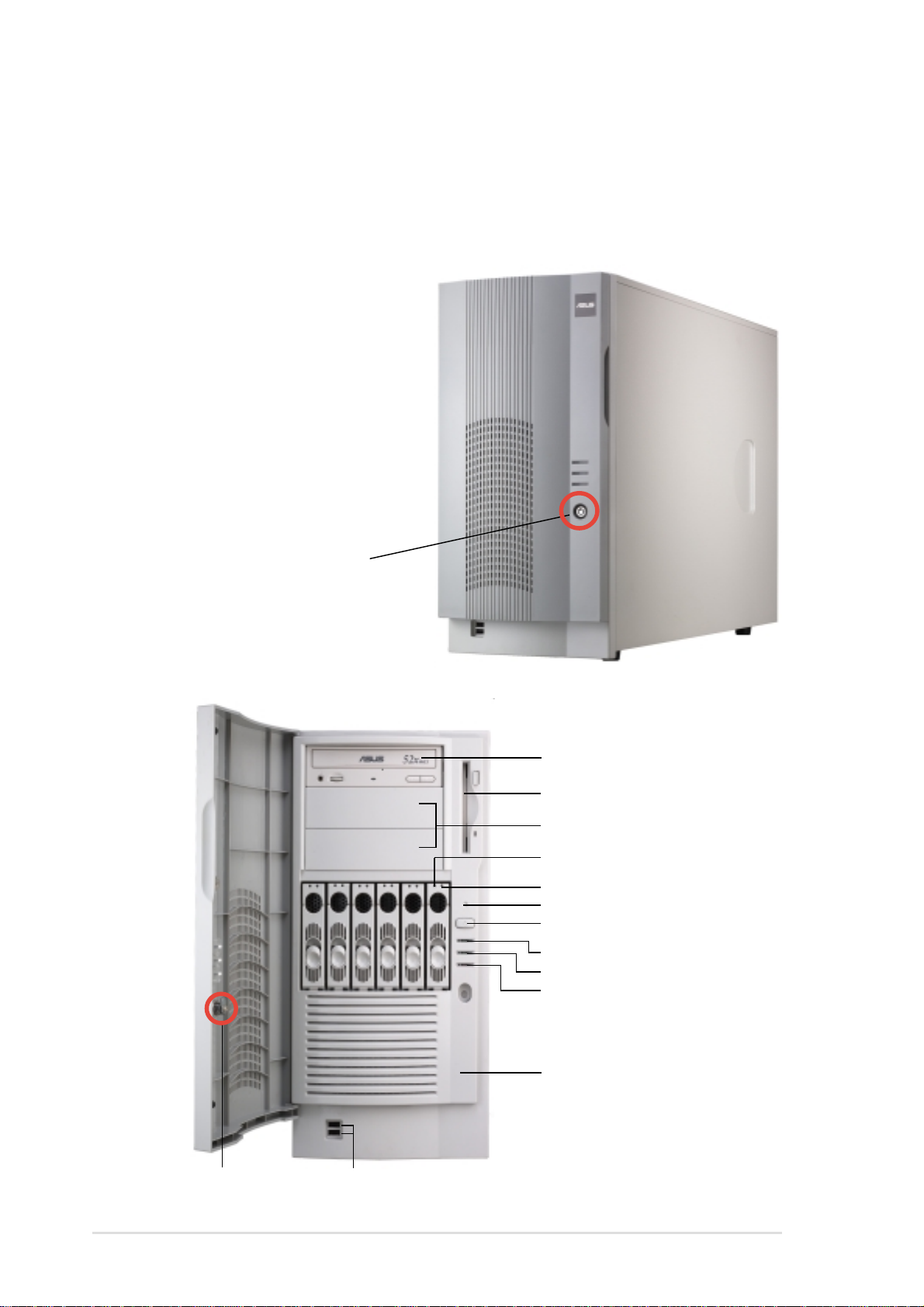
1.3 Front panel features
The AP1710-S5 chassis displays a stylish front bezel with lock. The bezel
covers the system components on the front panel and serves as security.
Open the bezel to access the front panel components.
The power and reset buttons,
LED indicators, CD-ROM drive,
floppy drive, and two USB ports
are located on the front panel.
For future installation of
5.25-inch devices, two drive
bays are available.
Security lock
Security lock
CD-ROM drive
Floppy disk drive
2 empty 5.25-inch bays
Drive Status LED
Drive Activity LED
Reset button
Power button
Power LED
HDD access LED
Message LED
Detachable front panel cover
USB ports
1-4
Chapter 1: Product introduction
Page 15
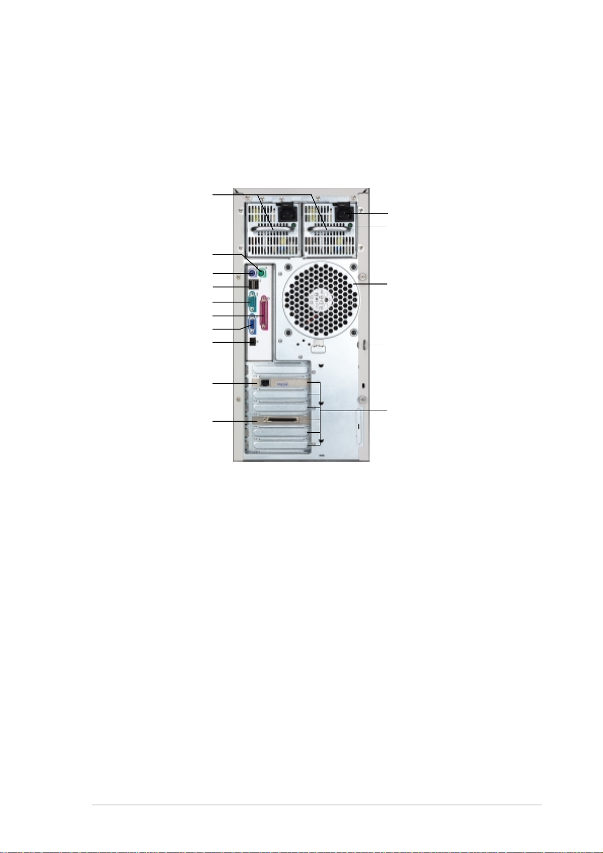
1.4. Rear panel features
The rear panel includes a slot for the motherboard rear I/O ports, six
full-length expansion slots, a chassis lock and intrusion switch, a vent for
the system fan, and redundant power supply modules.
Power supply modules
AC IN connector
AC Power status LED
P/S2 mouse port
P/S2 keyboard port
USB ports
Serial port
Parallel port
VGA port
Gigabit LAN port
12cm fan vent
Chassis lock
Gigabit LAN card
(optional)
SCSI card (optional
Expansion slots
ASUS AP1710-S5 user guide
1-5
Page 16
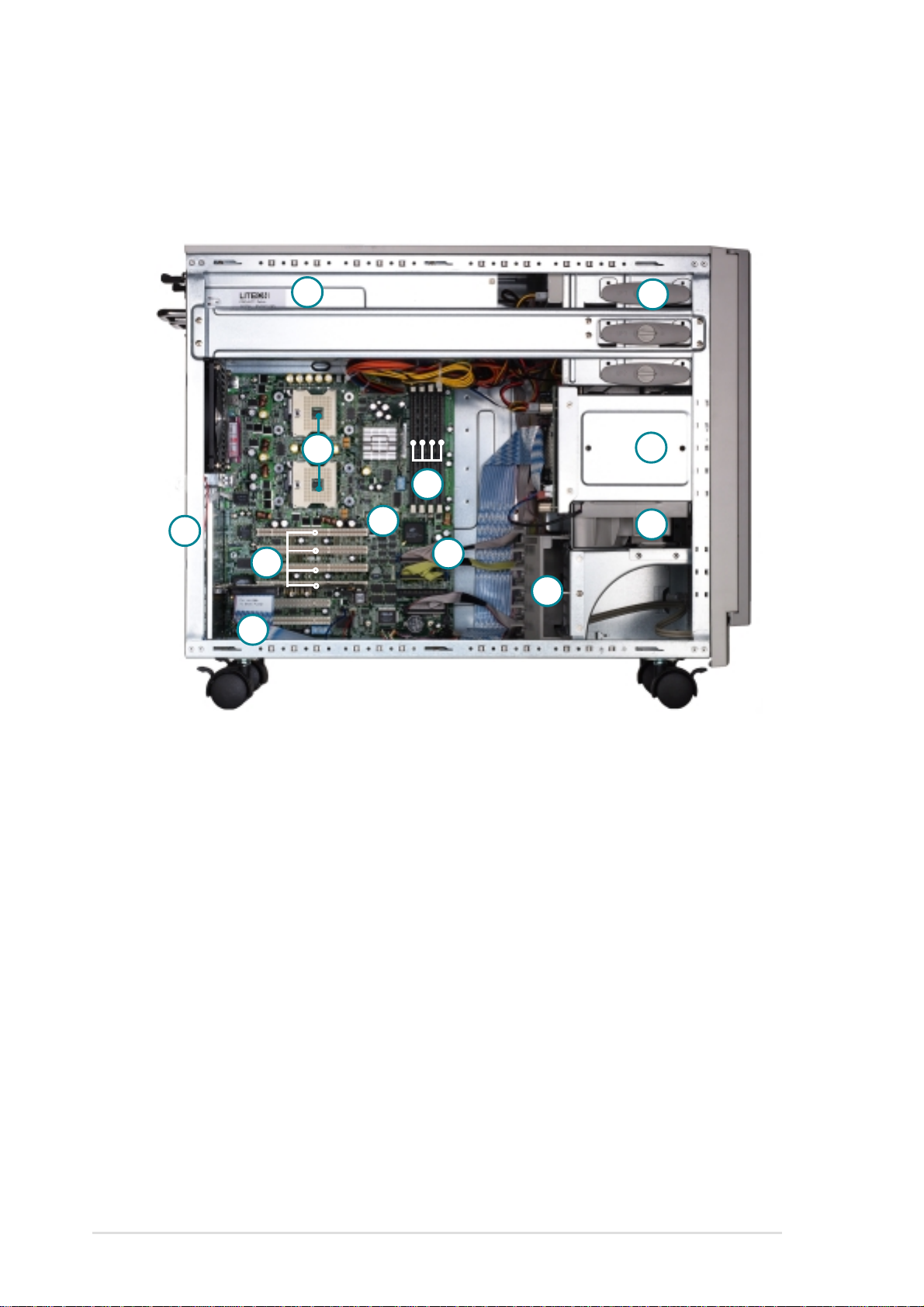
1.5 Internal features
The AP1710-S5 chassis includes the basic components as shown in the
picture below.
12
1
7
2
11
6
8
3
9
4
5
10
1. Redundant power supply cage
2. DDR DIMM sockets
3. IDE connectors
4. CD-ROM drive
5. HDD hot swap modules
6. 64-bit 3V PCI slots
7. CPU sockets
8. Internal 68-pin SCSI cable
9. PCI long card support guide
10.12 cm hot swap module blower
1 1. PRL-DL motherboard
12.Chassis intrusion sensor
1-6
Chapter 1: Product introduction
Page 17

1.6 LED information
The AP1710-S5 comes with five LED indicators. Refer to the picture for
the LED location and the following table for the LED status description
!
LED Icon Display Description
Drive Status LED Green Bridge board connected to backplane
Installed HDD is in good condition
Red HDD failure
Red-Blinking HDD rebuilding using the RAID card
SAF-TE* function
Drive Activity LED Blinking Read/write data into the HDD
Power LED ON System power ON
Blinking Suspend mode
HDD Access LED OFF No activity
Blinking Read/write data into the HDD
Message LED OFF System is normal; no incoming event
*SCSI Access Fault-Tolerant Enclosure
!
Blinking ASMS indicates a HW monitor event
The Power, HDD Access and Message LEDs are visible even if the
system front bezel is closed.
ASUS AP1710-S5 user guide
1-7
Page 18

1-8
Chapter 1: Product introduction
Page 19

Chapter 2
This chapter lists the hardware setup
procedures that you have to perform when
installing or removing system components.
ASUS AP1710-S5 user guide
Hardware setup
2-1
Page 20

2.1 Chassis cover
Before proceeding, prepare a Phillips and a flat head screw drivers that
you might need to facilitate installation.
2.1.1 Removing the cover
1. Loosen the two thumb screws that secure the side cover.
2. Slide the side cover for about half an inch toward the rear until it is
disengaged from the chassis.
1
2
2.1.2 Installing the cover
1. Match and insert the hooks of the cover to the elongated holes on the
side of the chassis. All the six hooks (three each on the top and
bottom) of the cover must properly fit the designated holes.
2. Slide the cover toward the front until it snaps in place.
3. Tighten the thumb screws to secure the cover.
Hole on the side
of the chassis
1
Hook on
the cover
3
2
2-2
Chapter 2: Hardware setup
Page 21

2.2 Motherboard information
The AP1710-S5 comes with the ASUS PRL-DL motherboard that uses the
extended ATX form factor measuring 12 inches x 10.5 inches (30.5 x 26.67
cm).
Make sure to unplug the power cord before installing or removing any
motherboard component or connection. Failure to do so may cause
you physical injury and may damage motherboard components.
The motherboard is secured in the chassis by nine (9) screws as indicated
by circles in the illustration below.
This side towards
the rear of the chassis
Refer to the motherboard user guide for detailed information on the
motherboard.
ASUS AP1710-S5 user guide
2-3
Page 22
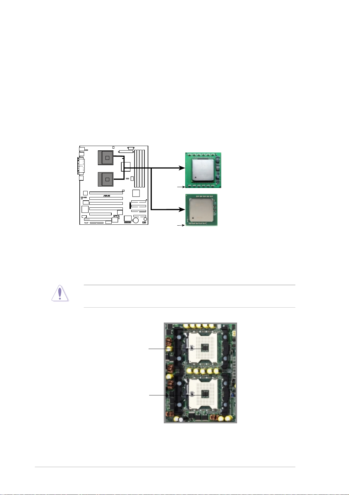
2.3 Central Processing Unit (CPU)
The motherboard comes with dual surface mount 604-pin Zero Insertion
Force (ZIF) sockets. The sockets are designed for the Intel® processors in
the 604-pin package with 512KB L2 cache. The processor includes the
Intel® NetBurst™ micro-architecture that features the hyper-pipelined
technology, rapid execution engine, 533/400MHz system bus, and
execution trace cache. Together, these attributes improve system
performance by allowing higher core frequencies, faster execution of
integer instructions, and data transfer rate of up to 4.26GB/s.
Prestonia
400Mhz FSB
Gold Arrow
®
PRL-DL
Prestonia
533Mhz FSB
Gold Arrow
PRL-DL Socket 604
Note in the illustration that the CPU has a gold triangular mark on one
corner. This mark indicates the processor Pin 1 that should match a
specific corner of the CPU socket.
Incorrect installation of the CPU into the socket may bend the pins and
severely damage the CPU!
CPU Socket 2
(outer socket)
CPU Socket 1
(inner socket)
2-4
Chapter 2: Hardware setup
Page 23

2.3.1 Installing the CPU
The motherboard supports either one or two CPUs. If you are installing
only one CPU, you MUST install it in CPU socket 1.
Follow these steps to install a CPU.
1. Locate the 604-pin ZIF sockets
on the motherboard. Unlock the
socket by pressing the lever
sideways, then lift it up to at least
115° angle.
Make sure that the socket lever is lifted up to at least 115° angle,
otherwise the CPU does not fit in completely.
2. Position the CPU above the
socket as shown.
3. Carefully insert the CPU into the
socket until it fits in place.
Marked Corner
The CPU fits only in one correct orientation. DO NOT force the CPU
into the socket to prevent bending the pins and damaging the CPU!
4. When the CPU is in place, press
it firmly on the socket while you
push down the socket lever to
secure the CPU. The lever clicks
on the side tab to indicate that it
is locked.
ASUS AP1710-S5 user guide
2-5
Page 24

2.3.2 Installing the heatsink and fan
The Intel® Xeon™ processors require specially designed heatsink and fan
assembly to ensure optimum thermal condition and performance.
Make sure that the heatsink with fan assembly is properly installed on the
motherboard. A tilted or improperly installed heatsink and fan assembly
can cause damage to motherboard CPU socket and/or CPU. To install the
CPU heatsink and fan:
1. Place the heatsink with fan
assembly on top of the installed
CPU. Make sure it fits the screw
holes of the heatsink bracket at
the bottom of the CPU socket.
(The heatsink bracket is
pre-installed in the motherboard.)
2. Tighten all four (4) screws. Make
sure all screws fit properly in
place.
Take caution in tightening
screws. Do not over-tighten
screws, doing so may
damage the motherboard!
TIP: Follow the sequence shown:
half-tighten the screw on one
corner of the heatsink and fan,
then the next screw on the other
corner and so on, making a cross
pattern. Repeat until all four
screws are tightened properly.
2
○○○○○○○○
○○○○○○○○
4
3
1
2-6
Make sure heatsink with fan assembly is mounted properly on the CPU
to avoid burning the CPU and/or CPU socket.
Chapter 2: Hardware setup
Page 25

3. When the heatsink and fan
assembly is in place, connect the
fan cable to the fan connector on
the motherboard labeled
CPUFAN1.
The fan cable plug is slotted
so it fits only in one
orientation. If it doesn’t fit
completely, try reversing it.
4. Make sure that the heatsink and
fan assembly is stable in place
and the fan power cable are
connected properly.
Don’t forget to connect the
CPU fan cable. Hardware
monitoring errors may occur
if you fail to plug the fan cable.
5. Repeat the same steps if you will
install another CPU in the
second CPU socket.
6. Use CPUFAN2 connector for the
second CPU heatsink and fan
assembly cable.
ASUS AP1710-S5 user guide
2-7
Page 26

2.4 System memory
The motherboard comes with four Double Data Rate (DDR) Dual Inline
Memory Module (DIMM) sockets. These sockets support up to 4GB
system memory using 184-pin registered PC2100/PC1600 DIMMs with
Serial Presence Detect (SPD) and Error Check and Correction (ECC).
DDR1
DDR2
DDR3
DDR4
104 Pins
®
PRL-DL
80 Pins
PRL-DL 184-Pin DDR DIMM Sockets
A DDR DIMM is keyed with a notch so that it fits in only one direction.
DO NOT force a DIMM into a socket to avoid damaging the DIMM.
The DDR SDRAM technology evolved from the mainstream PC66, PC100,
PC133 memory known as Single Data Rate (SDR) SDRAM. DDR memory
however, has the ability to perform two data operations in one clock cycle,
thus providing twice the throughput of SDR memory. For example, a
200MHz DDR DIMM will support a 100MHz memory bus, and a 266MHz
DDR DIMM will support a 133MHz memory bus.
DDR Data Transfer Rate DDR Base Frequency
266MHz 133MHz
200MHz 100MHz
A DDR DIMM has the same physical dimensions as an SDR DIMM, but it
has a 184-pin footprint compared to the 168-pin of the SDR DIMM. Also, a
DDR DIMM is single notched while an SDR DIMM is double notched.
Therefore, a DDR DIMM is not backward compatible with SDR, and should
be installed only in a socket specially designed for DDR DIMMs.
2-8
Chapter 2: Hardware setup
Page 27

2.4.1 Memory configurations
The motherboard supports system memory of up to 4GB in a one-way
non-interleaved configuration.
Memory configuration table
DIMM Socket 184-pin ECC DDR DIMM Total Memory
DDRA1 SDRAM 128MB, 256MB, 512MB, 1GB, 2GB (x1) =
DDRA2 SDRAM 128MB, 256MB, 512MB, 1GB, 2GB (x1) =
DDRB1 SDRAM 128MB, 256MB, 512MB, 1GB, 2GB (x1) =
DDRB2 SDRAM 128MB, 256MB, 512MB, 1GB, 2GB (x1) =
Total System Memory (Max. 4GB) =
The system chipset only supports PC2100/PC1600 registered ECC
DIMMs. Make sure to use only the specified DIMM types for stable
system operation.
ASUS AP1710-S5 user guide
2-9
Page 28
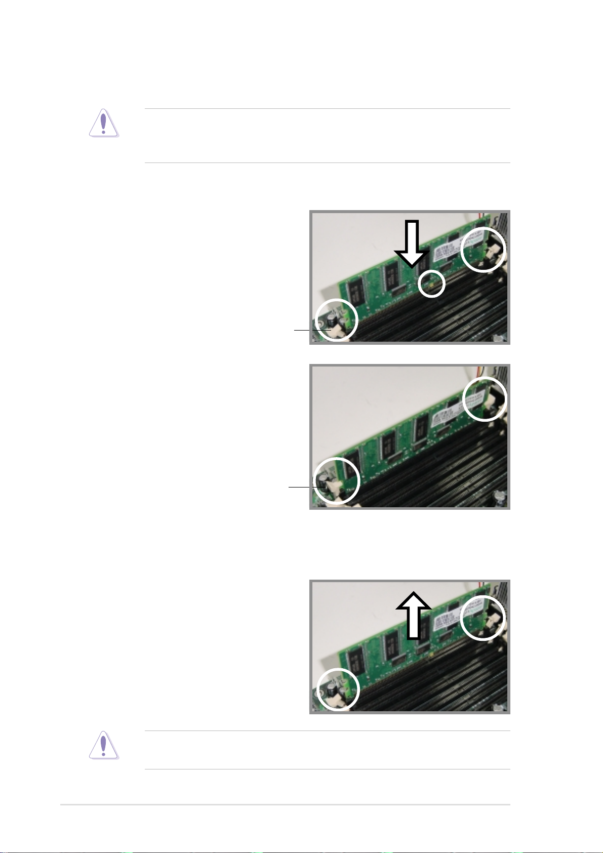
2.4.2 Installing a DIMM
Make sure to unplug the power supply before adding or removing
DIMMs or other system components. Failure to do so may cause
severe damage to both the motherboard and the components.
Follow these steps to install a DIMM.
1. Unlock a DIMM socket by
pressing the retaining clips
outward.
2. Align a DIMM on the socket such
that the notch on the DIMM
matches the break on the socket.
Unlocked Retaining Clip
3. Firmly insert the DIMM into the
socket until the retaining clips
snap back in place and the DIMM
is properly seated.
Locked Retaining Clip
2.4.3 Removing a DIMM
Follow these steps to remove a DIMM.
1. Press the retaining clips outward
simultaneously to unlock the
DIMM.
2. Remove the DIMM from the
socket.
Support the DIMM lightly with your fingers when pressing the retaining
clips. The DIMM might get damaged when it flips out with extra force.
2-10
Chapter 2: Hardware setup
Page 29
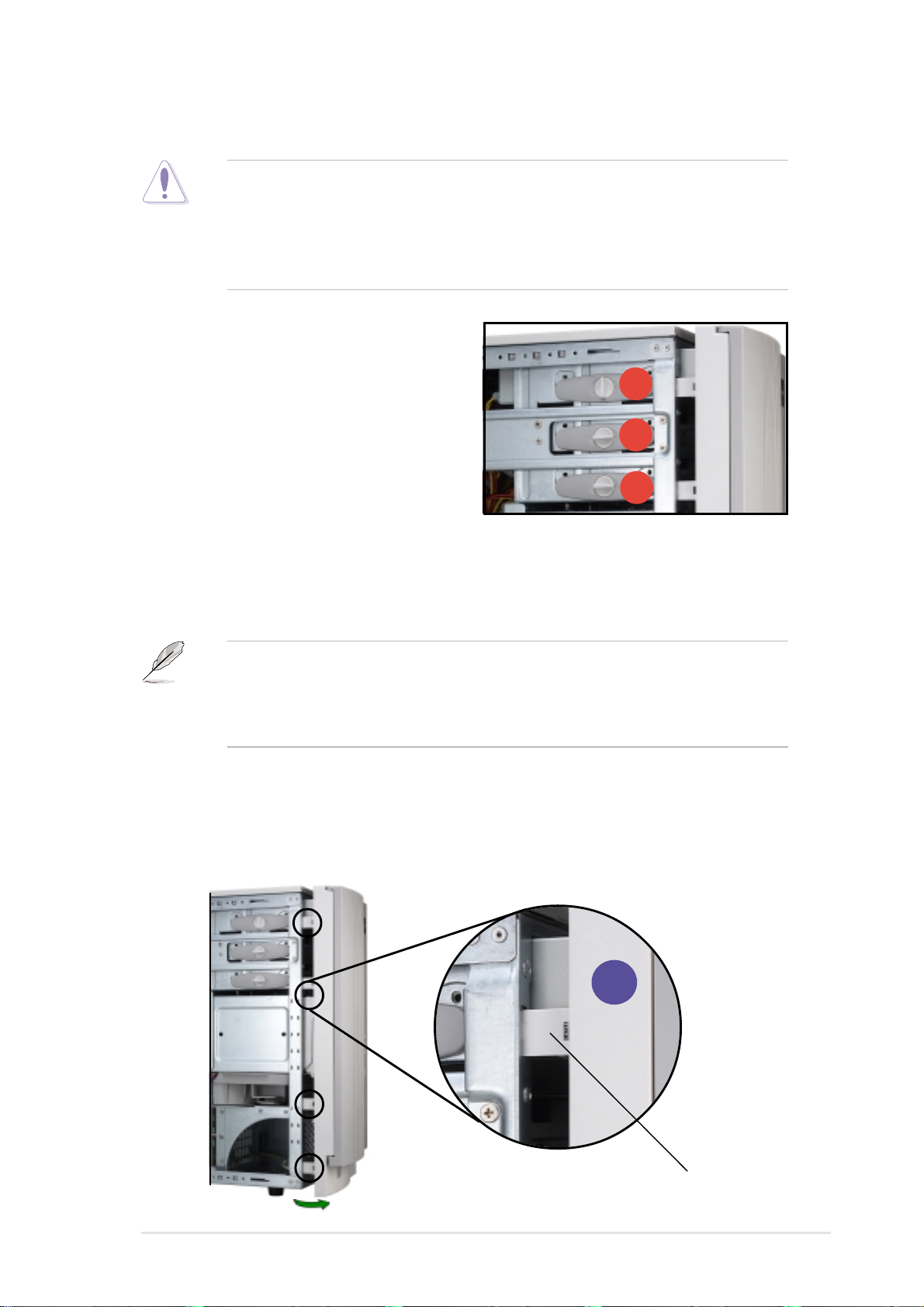
2.5 5.25-inch drives
If you have previously used and powered up the system, and that it
may be connected to an AC power source, make sure to unplug the
power cable before installing or removing any system components.
Failure to do so may cause severe damage to the motherboard and
other system components!
Three 5.25-inch drive bays are
located on the upper front part of the
chassis. A CD-ROM drive that comes
standard with the system package
occupies the uppermost bay (labeled
1). The two lower bays (labeled 2 and
3) are available for additional
5.25-inch devices.
1
2
3
2.5.1 Removing the front panel assembly
Before you can install a 5.25-inch drive, you should first remove the
front panel assembly (front bezel and front panel cover). The front
panel assembly is attached to the chassis through four hooked tabs
on the left side and four hinge-like tabs on the right side.
To remove the front panel assembly:
1. Use a flat-head screwdriver to detach the hooked tabs from the left
side of the front panel.
1
ASUS AP1710-S5 user guide
Hooked tab
2-11
Page 30

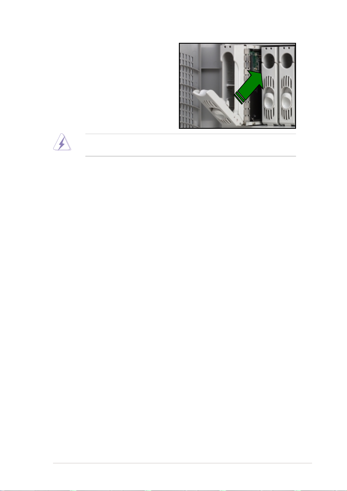
2. Pull and swing the left edge of the front panel outward.
3. Unhook the hinge-like tabs from the holes on the right side of the front
panel to completely detach the front panel assembly from the chassis.
3
Hinge-like tab
2
Do not use too much force when removing the front panel assembly..
2.5.2 Installing a 5.25-inch drive
To install a 5.25-inch drive:
1. Remove the metal cover of
the bay where you wish to
install the drive by pulling
the cover outward.
1
2-12
Chapter 2: Hardware setup
Page 31

2. From the side of the drive bay, unlock and remove the screwless drive
bay lock by turning the knob 45º counter-clockwise until it clicks on the
reference point near the “unlocked icon.”
Reference point
Unlocked icon
Knob
3. When released, pull out the
drive bay lock and set it aside.
2
3
4. Carefully insert a 5.25-inch
drive (such as a CD/DVDROM drive) into the bay until
it is in place.
The drive is in place when the screw holes on the drive align with the
holes on the side of the bay.
ASUS AP1710-S5 user guide
4
2-13
Page 32

5. Secure the drive to the bay
using the screwless drive bay
lock that you removed earlier.
a. Match the two pegs on the
lock to the holes on the drive
bay.
b. Turn the knob 45º clockwise
until it clicks on the reference
point near the “locked icon.”
Reference point
5a
5b
Locked icon
6. On the front panel assembly, detach the plastic bay cover opposite the
5.25-inch drive that you installed by pressing the two hooked tabs on
each side of the bay cover.
6
2-14
Bay cover tabs
Chapter 2: Hardware setup
Page 33

7. Re-install the front panel assembly (front bezel and front panel cover).
a. Insert the four hinge-like tabs to the holes on the right edge of the
chassis.
b. Swing the front panel to the left and fit the four (4) hooked tabs to the
left side of the chassis until the tabs snap in place.
7a
Hinge-like tab
7b
ASUS AP1710-S5 user guide
2-15
Page 34

2.6 Hard disk drives
The AP1710-S5 comes with six externally accessible drive bays. In each
drive bay is a removable tray for mounting an SCA SCSI hard disk drive.
2.6.1 Installing a hard disk drive
Follow these steps to install a SCSI hard disk drive.
1. Open the front panel door.
2. Release the drive bay by lifting
the spring lock upwards, then pull
the tray lever outwards.
3. The tray will slightly eject after
the tray lever is pulled down. Pull
the hard disk drive tray out from
the chassis.
4. Place an SCA SCSI hard drive
into the drive tray. Secure the
drive with four (4) round head
screws.
Spring lock
Tray lever
2-16
Chapter 2: Hardware setup
Page 35
5. Insert the hard disk drive tray into
the bay until it fits.
6. Push the tray lever back in place.
Make sure that the HDD tray is completely in place before you push
the handle back to avoid damaging the drive and the tray.
ASUS AP1710-S5 user guide
2-17
Page 36

2.7 Expansion cards
The chassis is designed with a screwless expansion slot frame on the rear
panel. This design feature allows you to install or remove an expansion
card in less steps.
Make sure to unplug the power cord before installing or removing
expansion cards. Failure to do so may cause physical injury, and
damage to the card and motheboard components!
2.7.1 Installing a standard size expansion card
To install an expansion card:
1. Release the card lock.
a. Press the card lock lever.
b. The card lock flips up.
Card lock lever
Card lock
1a
2. Slide out the metal bracket
opposite the PCI slot where you
wish to install the expansion card.
You may use a flat-head
screwdriver to easily remove the
bracket.
1b
2
2-18
Chapter 2: Hardware setup
Page 37

3. Install the expansion card
making sure that it is properly
seated on the slot.
4. Press the end of the card lock
marked “LOCK” to secure the card
on the slot. A light click indicates
that the card is locked in place.
3
Lock
4
Refer to the card documentation for the card configuration details, and
to the motherboard user guide in case you need to configure any
jumpers after installing the expansion card.
4
ASUS AP1710-S5 user guide
2-19
Page 38

2.7.2 Installing a long expansion card
If you are installing a long expansion card, such as some types of RAID
cards, use the plastic card support located near the front of the chassis
(under the backplane board) to keep the expansion cards firmly seated on
the slots. This card support has individual card guides that correspond to
each expansion slot.
Plastic long-card support
To install a long expansion card:
1. Position the expansion card above the PCI slot that you wish to use.
2. Insert one end of the card to the card guide opposite the PCI slot, and
align the bracket end of the card to the expansion slot on the rear
panel.
3. Slide in the card down until it is properly seated on the slot.
4. Secure the card using the screwless lock on the card guide.
2-20
Screwless lock
Chapter 2: Hardware setup
Page 39

2.7.3 Removing an expansion card
To remove an expansion card:
1. Release the card lock.
a. Press the card lock lever.
b. The card lock flips up.
Card lock lever
Card lock
1a
2. Pull out the card from the PCI
slot.
1b
2
3. Press the end of the card lock marked “LOCK” to return it in place.
ASUS AP1710-S5 user guide
2-21
Page 40
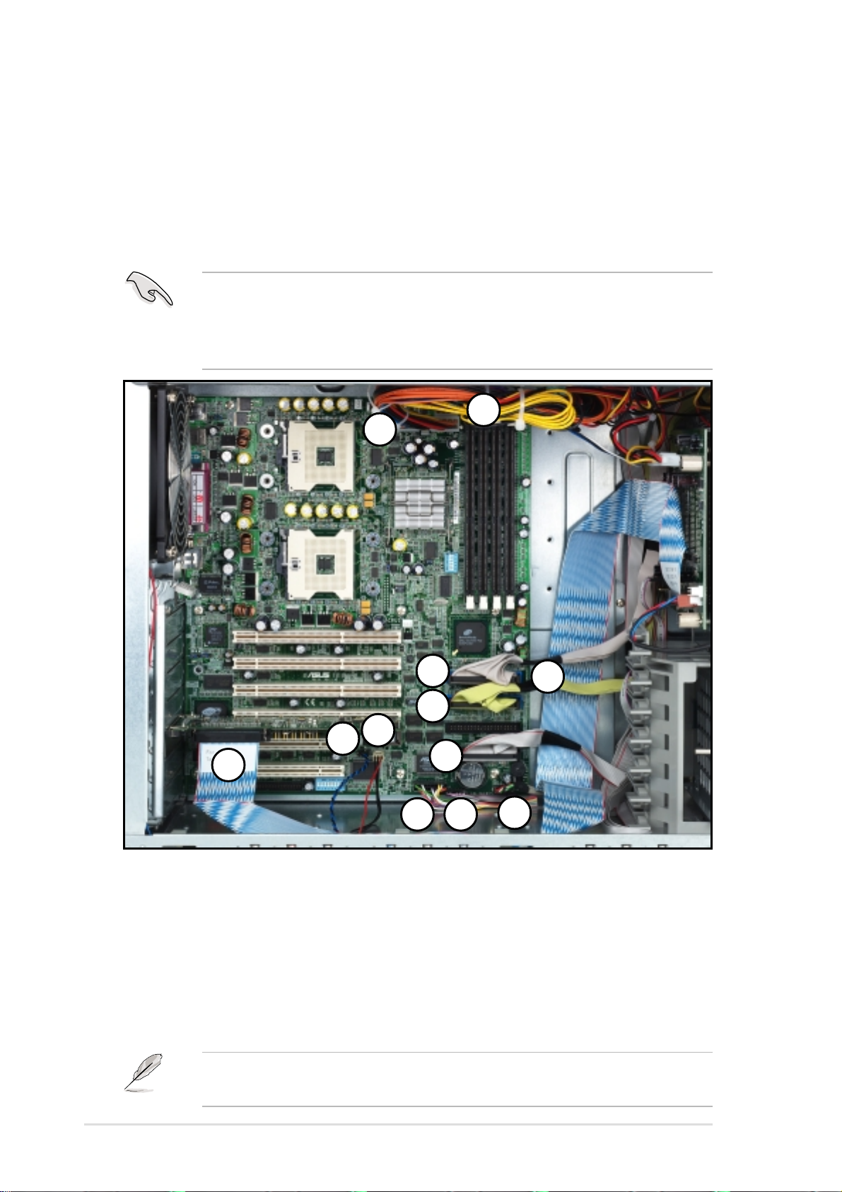
2.8 Cable connections
2.8.1 Motherboard connections
The AP1710-S5 chassis includes the power and signal cables that you
need to connect to the motherboard, SCSI backplane and to the devices
that you will install.
Most of the cables for the chassis kit are already connected upon
shipment. When installing system devices and connecting cables,
make sure that all cables are routed properly for better system stability
and performance. Refer to the picture below when arranging cables.
11
10
8
9
7
2
1
12
Standard cables connected to the motherboard
1. Chassis intrusion
2. Chassis fan
3. 20-pin system panel
4. SMBus panel to backplane
5. Front USB connector
6. Floppy disk drive
Refer to the motheboard user guide for detailed information on the
connectors.
6
3
4
7. Secondary IDE
8. Primary IDE
9. HDD cable
10. 24-pin A TX power
11. 8-pin 12V AUX power
12. SCSI controller
5
2-22
Chapter 2: Hardware setup
Page 41
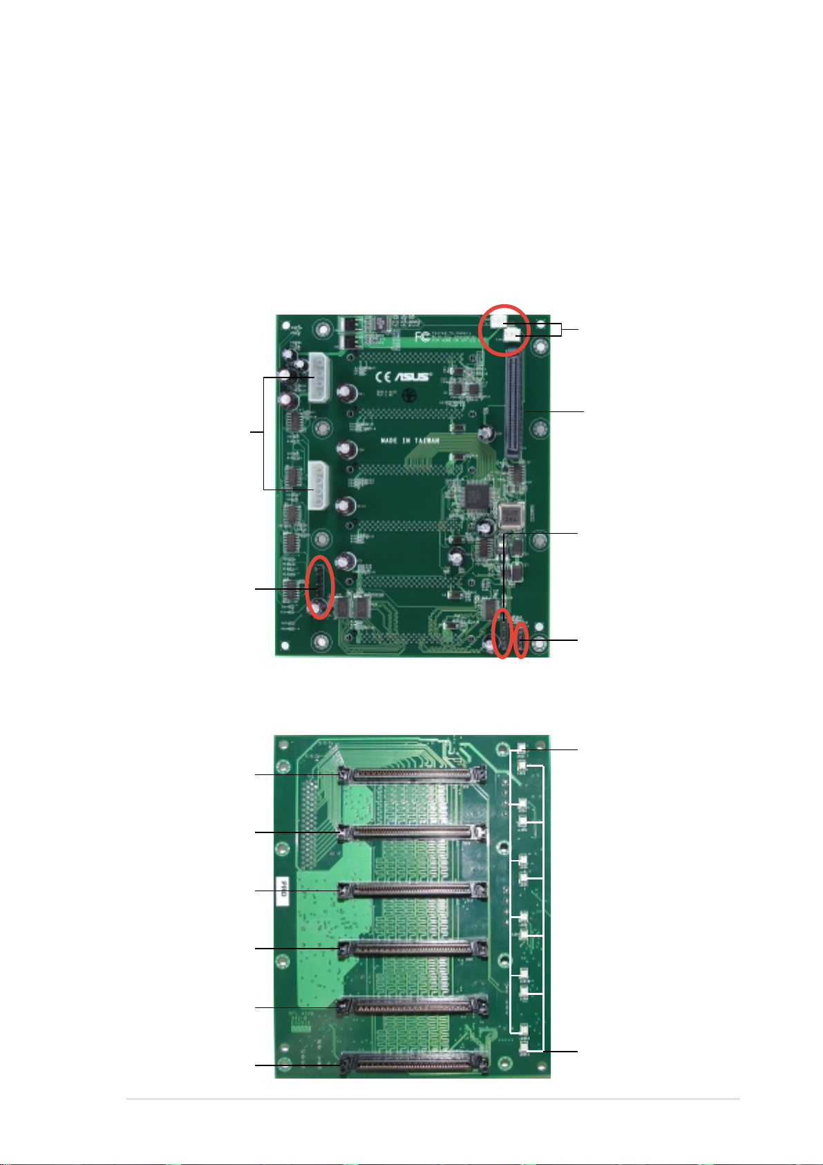
2.8.2 SCSI backplane connections
The SCSI backplane has six 68-pin SCSI connectors to support SCA SCSI
hard disks. The backplane design incorporates a hot-swap feature to allow
easy connection or removal of SCSI hard disks. The LED connectors on
the backplane connect to the front panel LEDs to indicate HDD access,
HDD failure, thermal failure, or fan failure.
Front side
Fan connectors
68-pin SCSI
Power connectors
(connects power plugs
from the power supply)
connector
(connect to the SCSI
connector on the
motherboard)
SMBus connector
(connects the 6-pin plug
from the power supply)
Back side
SCSI ID = 0
Disk drive 1
SCSI ID = 1
Disk drive 2
SCSI ID = 2
Disk drive 3
SMBus connector
(connect to the SMBus
connector on the
motherboard)
HDD Access LED
(connect to the HDD
LED connector on the
motherboard)
HDD status LEDs
SCSI ID = 3
Disk drive 4
SCSI ID = 4
Disk drive 5
SCSI ID = 5
Disk drive 6
ASUS AP1710-S5 user guide
HDD activity LEDs
2-23
Page 42
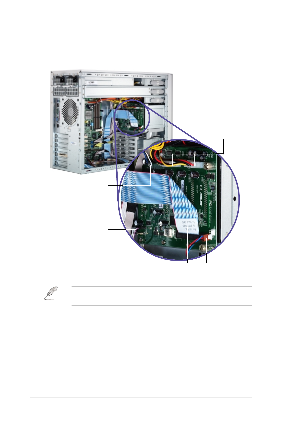
The following picture shows the SCSI backplane installed in the system
and the cables connected to it.
Power cables from
power supply
SMBus cable from
power supply
SMBus cable from
motherboard
connector
Fan cables
SCSI cable Fan cable
Use power plugs from both redundant power supply modules to ensure
power redundancy.
2-24
Chapter 2: Hardware setup
Page 43

2.9 Removable components
You may need to remove previously installed components when installing
or removing system devices. This section describes how to remove the
following components:
1. Chassis fan
2. HDD blower
3. Floppy disk drive
2.9.1 Chassis fan
To remove the 12-cm chassis fan:
1. Disconnect the 3-pin fan cable
from the connector on the
motherboard.
2. Use a flat screwdriver to push
the pin locks on the four corners
of the fan from the inside of the
chassis.
4. Power supply modules
5. Power supply case
6. Roller wheels
Pin lock (tail-end)
3. Pull out the pin locks from the
rear panel.
4. Remove the chassis fan.
ASUS AP1710-S5 user guide
2-25
Page 44

2.9.2 HDD blower
To remove the HDD blower:
1. Disconnect the 3-pin HDD blower cable from the FAN 1 connector on
the SCSI backplane.
1
HDD blower cable
2. Press the tab at the bottom of
the blower to release it from the
chassis.
3. Pull out the HDD blower.
HDD blower
HDD blower
3
2
Blower tab
2-26
Chapter 2: Hardware setup
Page 45
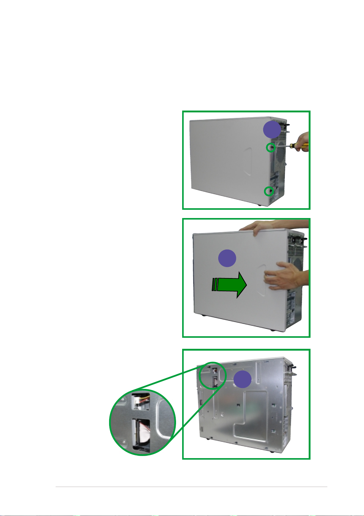
2.9.3 Floppy disk drive
To remove the floppy disk drive:
1. Remove the front panel assembly. Refer to “2.5.1 Removing the front
panel assembly” on page 2-11.
2. Use a Phillips head screw driver
to remove the right side chassis
cover screws.
3. Pull out and detach the right
side chassis cover. Set aside
the cover.
2
4. Locate the floppy disk drive
cable and power connectors.
3
4
ASUS AP1710-S5 user guide
2-27
Page 46
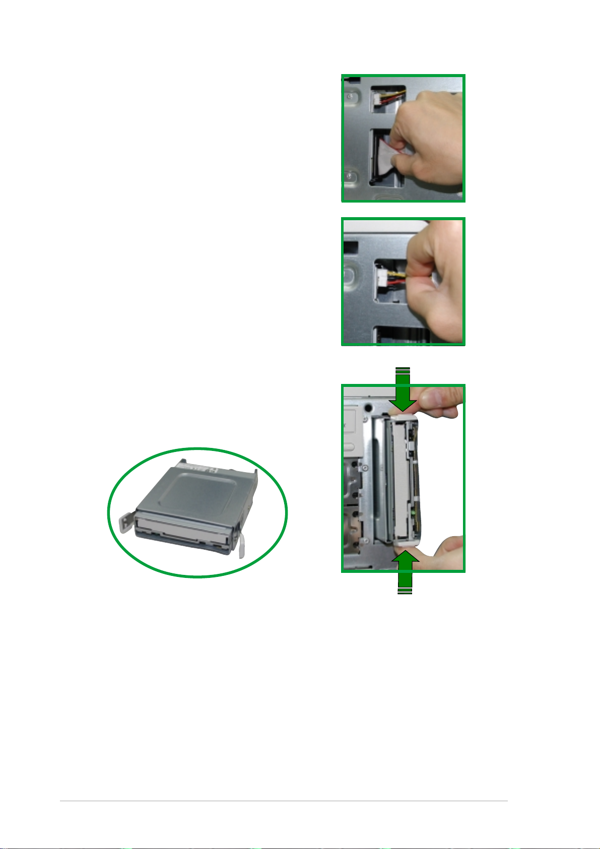
5. Detach the floppy disk drive
cable.
6. Detach the floppy disk drive
power cable.
7. Squeeze the floppy disk drive
tray tabs while pulling the tray
out of the chassis.
Floppy disk drive tray
2-28
Chapter 2: Hardware setup
Page 47
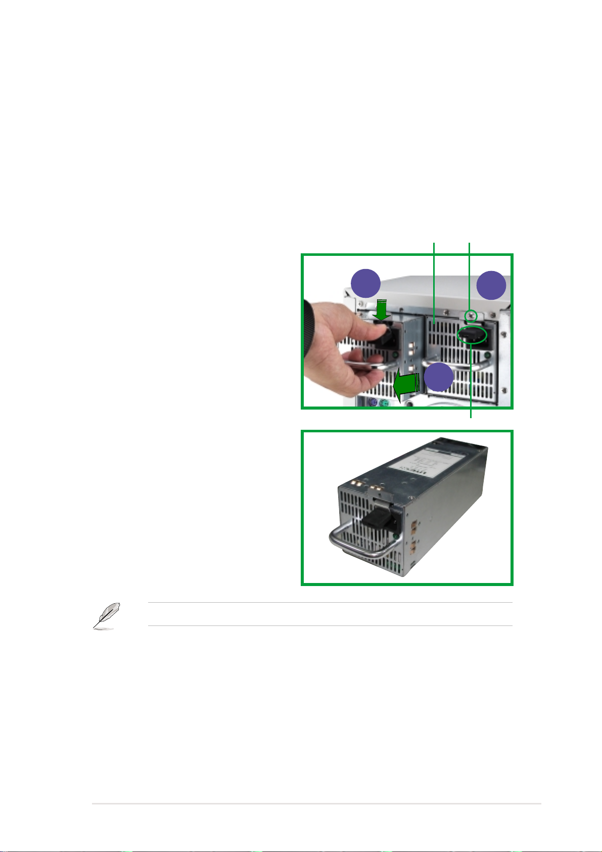
2.9.4 Power supply modules
The AP1710-S5 has two power supply modules. These hot swap power
modules can be removed or installed while the server is powered ON. One
power module is enough to power the server. When two power supply
modules are installed, the task of providing power to the server is shared.
To remove the redundant power supply module:
1. Remove the power module
screw.
2. Press down the rubber lever
3. Pull the power module handle
from the chassis.
Redundant Power Housing
2
500W Redundant
Power Module
Screw
1
3
Lever
Refer to the Appendix for the redundant power module specification.
ASUS AP1710-S5 user guide
2-29
Page 48

2.9.5 Power supply case
The redundant power modules are secured in a power supply case that
connects to various power supply connectors on the SCSI backplane and
the motherboard.
To remove the power supply case:
1. Remove the two (2) top
chassis cover screws to release
chassis top panel cover.
2. Remove all power cable
connections from SCSI
backplane and motherboard.
3. Remove the six (6) chassis bar
screws and release chassis bar.
4. Remove the two (2) right-side
chassis cover screws to release
right-side cover.
2-30
Chapter 2: Hardware setup
Page 49

5. Remove the four (4) power
case side screws.
6. Remove the six (6)
power case top screws.
Make sure the power case is well supported or held when releasing the
power case screws. The power case may accidentally drop and cause
damage to other server system components.
7. Slowly pull-out the power case.
ASUS AP1710-S5 user guide
2-31
Page 50

2.9.6 Roller wheels
The chassis comes with four roller wheels for convenient transport. Each
wheel has a brake lock to stabilize the chassis in place.
To remove the chassis wheels:
1. Lay the chassis in its side.
2. Use a Phillips screwdriver to remove the screws that secure the
wheels to the bottom of the chassis.
Brake lock
2-32
Remove the chassis roller wheels if you wish to mount the system to a
rack. Refer to the Rackmount Kit manual for more information.
Chapter 2: Hardware setup
Page 51

Appendix
This appendix lists the common problems
that you may encounter while using the
AP1710-S5 server. It lists the possible
causes of the problems and offers
solutions. You may refer to this part and try
to solve simple problems before calling
customer support. The appendix also
contains the redundant power module
specifications for your reference.
ASUS AP1710-S5 user guide
Appendix
A-1
Page 52
A.1 Simple fixes
Some problems that you may encounter are not due to defects on the
system or the components. These problems only requires simple
troubleshooting actions that you can perform by yourself.
Problem Action
The power LED on the server or
on the monitor do not light up
The keyboard does not work
The mouse does not work
The system does not perform
power-on self tests (POST) after
it was turned on
1. Check the power cable
connection on the system rear
panel if properly connected.
2. Make sure that the power
cables are connected to a
grounded power outlet.
Check the keyboard cable if
properly connected to the
keyboard port.
Check the mouse cable if properly
connected to the mouse port.
1. Check the memory modules
and make sure you installed
the DIMMs the system
supports.
A-2
2. Make sure that the DIMMs are
properly installed on the
sockets.
Appendix: Troubleshooting
Page 53

Problem Action
The system continuously beeps
after it was turned on
The message “Non-system disk
or disk error” appears
1. Check the memory modules
and make sure you installed
the DIMMs the system
supports.
2. Make sure that the DIMMs are
properly installed on the
sockets.
3. Check if it has a VGA ouput.
1. Check if a bootable HDD is
active.
2. Check if the HDDs are
properly installed. On SCSI
models, make sure that the
cables are properly connected
to the SCSI connectors on the
backplane.
Network connection not
available
1. Make sure that the network
cable is connected to the
RJ-45 port on the rear panel.
2. Make sure that you have
installed the LAN drivers from
the support CD.
ASUS AP1710-S5 user guide
A-3
Page 54

A.2 Redundant power module specifications
Output Voltage Regulation
Output Voltage Min (V) Nom (V) Max (V) Ripple/Noise
+3.33V 3.20 3.33 3.50 50mVp-p
+5V 4.75 5.00 5.25 50mVp-p
+12V 11.4 12.00 12.60 120mVp-p
-12V -10.8 -12.00 -13.20 120mVp-p
+5VSB 4.75 5.00 5.25 50mVp-p
Output Current Capacity
Output Voltage Min (A) Max (A) Max. Load (W)
+3.33V 1.0 24.5 81.6
+5V 1.0 17.5 87.5
+12V 2.0 25.0 300
-12V 0.0 0.2 2.4
+5VSB 0.1 2.0 10
Over-Voltage Protection (OVP)
Voltage Min (V) Max (V)
+3.33V 3.7 4.5
+5V 5.5 6.5
+12V 12.9 14.2
A-4
Appendix: Troubleshooting
 Loading...