

Page 1
®
AP1700
Intel® Xeon Tower/5U Rackmount Server
with 533MHz FSB support
User’ s Manual
Page 2

System Package Contents
The following checklist enumerates the components included in the
standard system package.
1) ASUS AS-35 Tower/5U Rackmount chassis
2) ASUS PR-DLS533 motherboard
3) 500W+500W redundant power supply
4) Backplane board (BP6LS-AS35)
5) CD-ROM drive (1 piece)
6) Floppy disk drive (1 piece)
7) Special heatsink with fan assembly (2 sets)
8) Hot swap SCSI hard disk drive tray (6 units)
9) AC power cord (2 pieces)
10) Support CD that includes drivers, utilities, ASUS System
Monitoring Agent (ASMA) with the ASUS Server Web-based
Management (ASWM)
11) Trend Micro Server Protect anti-virus software full user version CD
enterprise edition
12) Motherboard user guide
13) System user guide
14) LSI SCSI controller user guide
15) ASMS (ASMA + ASWM) user guide
16) chassis roller wheels (4 sets)
17) Keys x 2
18) Screws and labels
Optional:
1) ASUS AS-35 5U rackmount rail kit
2) LSI MegaRAID 320-0 Zero channel RAID card
If any of the above items is missing, contact your dealer.
I-4 ASUS AP1700
Page 3

Chapter 1
This chapter describes the general features of
the AP1700 system server. It includes sections
on front panel, rear panel and internal
specifications.
User’s Manual 1-1
System Overview
Page 4

1.1 System Features
The ASUS AP1700 server is a stylish server system featuring the
ASUS PR-DLS533 motherboard. The server supports the Intel® Xeon
processor in a 604-pin socket, and includes the latest I/O, LAN, and
video technologies through the chipsets embedded on the
motherboard.
The following are highlights of the server’s many features:
• Chassis: Pedestal or rackmount 5U with removable front door
bezel and chassis foot stand or roller-wheels.
• Motherboard: ASUS PR-DLS533
• Chipset: RCC Grand Champion LE Server 3.1 (GCLE), RCC
Champion South Bridge 5.0 (CSB5), RCC Champion I/O Bridge
2.0 (CIOB-X2)
• Memory: Supports six 184-pin DDR DIMM sockets, PC2100/
PC1600 registered ECC DDR DIMMs, 128MB to 12GB system
memory.
™
• Processor: Support for two Intel
®
XeonTM processor up to 2.8
GHz+ frequency.
• Network Controller: Intel
®
82544GC Gigabit Ethernet controller ,
Intel® 82540EM Gigabit Ethernet controller
• Drive Controller: LSI 53C1030/64-bit/100MHz Dual Ultra-320
channels. Two UltraDMA 100 IDE channels.
• Graphics: ATI RAGE-XL PCI with 8MB PC-100 SDRAM video
memory
• Onboard IO: 1 X PS/2 mouse port, 1 X PS/2 keyboard slot, 1 X
serial ports, 1 X 15-pin VGA port, 1 X floppy drive slot, 2 X IDE
ports, 4 X USB ports, 2 X RJ-45 LAN port, 2 X 68-pin SCSI
connectors
• Special IO: IPMB connector, SM-Bus
• Expansion: 5 X 64-bit 3V PCI-X slots, 1 X 32-bit/33Mhz 5V PCI
slot
• Device Bays: 6 X hot-swap trays for SCA SCSI hard drives, 3 X
5.25 inch bay, 1 X floppy disk drive bay.
• Power Supply: 500W redundant power supply.
• Hardware Monitors: Voltage, temperature, Automatic System
Restart (ASR), fan speed.
1-2 ASUS AP1700
Page 5

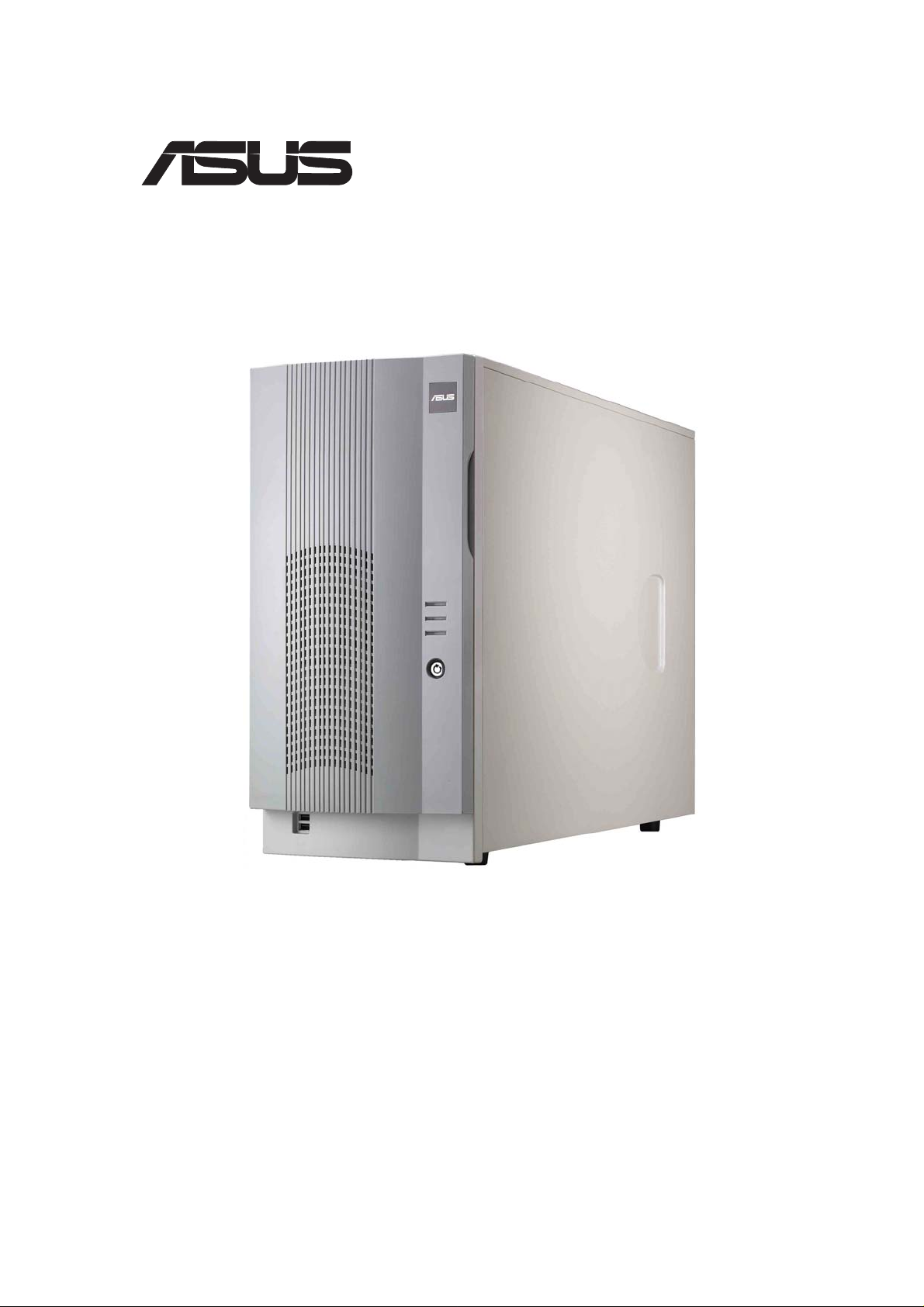
1.2 Front Panel Features
The front panel allows easy access to the hard disk drives. The power
and reset buttons, LED indicators, optical drive, floppy drive and two
USB connectors are also located on the front panel. For future
installation of 5.25 devices, there are two drive bays available. The
front panel of the server is protected by a door and lock for added
security.
CD-ROM Drive
3.5” Floppy Drive
2 empty 5.25” bays
Drive Status LED
Drive Activity LED
Reset Button
Power Button
Power LED
HDD Access LED
Message LED
6 SCA SCSI Hard
Drive Swap Trays
2 USB PortsFront Door Lock
For more detailed information of each LED display, refer to
“1.5 LED Table” on page 1-6.
User’s Manual 1-3
Page 6

1.3 Rear Panel Features
The server rear panel includes the connectors, the system devices,
a chassis lock and six full-length expansion cards slot. The following
shows the features on the rear side of the server.
AC Power IN Connector
AC Power Status LED
PS/2 mouse port
PS/2 keyboard port
2 x USB ports
Serial port
Parallel port
VGA port
Dual Gigabit
LAN ports
12 cm chassis fan
Chassis Lock
6 Full-Length PCI Slots
High Density 68-pin
SCSI Connector
You may secure the chassis lock with an additional padlock
or other security device for added server system security.
1-4 ASUS AP1700
Page 7

1.4 Internal Features
The standard components inside the server include the motherboard,
power supply, floppy and CD-ROM drives, and cables. The picture
below shows the standard components of the server.
1
2
7
11
3
6
8
4
5
10
9
1. Redundant power
supply cage
2. 6 x DDR DIMM sockets
3. 2 x IDE cable
4. 5
1/4” CD-ROM drive
5. HDD hot swap modules
6. 5 x 64 bit 3V PCI-X slots
7. CPU sockets
8. Internal 68-pin SCSI cable
9. PCI Long Card support guide
10. 12 cm hot swap
module blower
11. PR-DLS533 motherboard
User’s Manual 1-5
Page 8

1.5 LED Table
The following table describes the LED display found on the front panel
and rear panel of the AP1700 server system.
Icon
1
1
2
3
LED
Drive Status
LED
Drive Activity
LED
Power LED
HDD Access
LED
Display Description
Green
Red
Red blinking
Blinking
ON
Blinking
OFF
Blinking
HDD insert and
Power status is good
HDD Fail
HDD rebuilding (RAID
card SAF-TE* function)
HDD Read/Write data
System power ON
Suspend Mode
No activity
Read/Write data in HDD
OFF
4
*SCSI Access Fault - Tolerant Enclosure
Message
LED
Blinking
Normal/No incoming event
ASMS indicate HW
monitor event
1
2
3
4
Only RAID cards with SAF-TE feature is enabled with HDD
rebuilding function.
1-6 ASUS AP1700
 Loading...