

AP1600R-E2
Intel® XeonTM 1U
(BA2)
AP1600R-E2(BA2) ASUSPRO 1600R-E2(BA2)
1) 2)
Intel Xeon Pentium Intel
Windows MS-DOS Microsoft
©2004
AP1600R-E2(BA2)
V1 T1732
ASUS AP160
2004 11
2
ASUSTeK COMPUTER INC.
15
886-2-2894-3447
0800-093-456
886-2-2890-7698
www.asus.com.tw
ASUS COMPUTER INTERNATIONAL
44370 Nobel Drive, Fremont ,CA 94538, USA
+1-502-995-0883
+1-502-933-8713
tmdl@asus.com
+1-502-995-0883
+1-502-933-8713
tsd@asus.com
www.asus.com
ASUS COMPUTER GmbH
Harkort Str. 25, D-40880 Ratingen, Germany
49-2102-95990
49-2102-959911
www.asuscom.de
www.asuscom.de/sales
49-2102-95990 ... /
49-2102-959910 ...
49-2102-959911
www.asuscom.de/support
AP1600R-E2(BA2)
3
..........................................................................................................
..........................................................................................................
..........................................................................................................
....................................................................
8
8
9
10
1.1
1.2
1.3
1.4
1.5
1.6 LED
1.6.1
1.6.2
1.7
2.1
2.2
2.2.1
2.2.2
2.3
2.3.1
2.3.2
2.3.3
2.4
2.4.1
2.4.2
2.4.3
2.4.4
2.5
2.6
2.6.1
2.6.2
2.7
..........................................................
.........................................................................................
.............................................................................................
.................................................................................................
.................................................................................................
.................................................................................................
................................................................................
................................................................................
................................................................................
.................................................................................................
..........................................................
.............................................................................................
.................................................................................................
................................................................................
................................................................................
CPU
CPU
CPU
.............................................................................................
................................................................................................
...........................................................................................
...................................................................................................
PCI-X
...............................................................................................
...............................................................................
..........................................................................
............................................................................
..........................................................................
....................................................................................
............................................................................
............................................................................
.....................................................................
..................................................................................
ASUS AP160
1-1
1-2
1-3
1-4
1-5
1-5
1-6
1-6
1-7
1-8
2-1
2-2
2-3
2-3
2-4
2-5
2-5
2-6
2-7
2-8
2-8
2-8
2-9
2-9
2-10
2-12
2-12
2-14
2-15
4
2.8
2.8.1
2.8.2
2.8.3
2.8.4
2.8.5
2.9 SATA
.......................................................................................
......................................................................................
......................................................................................
..................................................................................
..........................................................................................
..........................................................................................
........................................................................
2-16
2-16
2-16
2-17
2-18
2-20
2-21
3.1
3.2
3.3
3.4
4.1
4.2
4.3
.................................................................................................
.................................................................................................
.................................................................................
.........................................................................................
.............................................................................................
BIOS
5.1 BIOS
5.1.1
5.1.2
5.1.3
5.1.4
5.2 BIOS
5.2.1 BIOS
5.2.2
5.2.3
5.2.4
5.2.5
5.2.6
5.2.7
5.2.8
5.2.9
AFUDOS BIOS
CrashFree BIOS 2 BIOS
................................................................................
.....................................................................................
......................................................................................
..........................................................................................
..........................................................................................
......................................................................................
..............................................................................................
..............................................................................
.............................................................................
.......................................................................
..................................................................
............................................................................
...................................................
.............................
....................................................................
......................................................................
..........................................................................
3-2
3-2
3-3
3-4
4-2
4-5
4-11
5-2
5-2
5-3
5-5
5-7
5-10
5-11
5-11
5-11
5-12
5-12
5-12
5-12
5-12
5-12
AP1600R-E2(BA2)
5
5.3 Main Menu
5.3.1 System Time [XX:XX:XXXX]
5.3.2 System Date [Day XX/XX/XXXX]
5.3.3 Legacy Diskette A [1.44M, 3.5 in.]
5.3.4 IDE
2.3.5 IDE IDE Configuration
5.3.6
5.4 Advanced menu
5.4.1 USB
5.4.2 MPS MPS Configuration
5.4.3
5.4.4 CPU Configuration
5.4.5
5.4.6 OnBoard Devices Configuration
5.4.7 PCI
5.5 Power menu
5.5.1 ACPI APIC Support [Enabled]
5.5.2
5.5.3
5.6
5.6.1
5.6.2
5.6.3
5.7
Boot Menu
BIOS Exit menu
........................................................................
....................................................
.............................................
.............................................
..............................................................................
........................................
System Information
.............................................................
USB Configuration
Remote Access Configuration
Chipset
Boot Device Priority
Security
..................................................................
PCI PnP
...................................................................
APM Configuration
Hardware Monitor
.....................................................................
Boot Settings Configuration
................................................................
..............................................
.............................................
...........................................
.................................................
....................................................
........................................
............................................
...........................................................
......................................
......................
..................
..............................
.........................
5-13
5-13
5-13
5-13
5-13
5-15
5-16
5-17
5-17
5-18
5-19
5-20
5-21
5-23
5-24
5-26
5-26
5-27
5-29
5-31
5-30
5-32
5-33
5-36
..............................................................................................
A-2
ASUS AP160
6
IC
AP1600R-E2(BA2)
7
UPS
IC
ASUS AP160
8
1.
2.
step-by-step
3.
4.
Jumper
5. BIOS
BIOS BIOS
AP1600R-E2(BA2)
AP1600R-E2(BA2)
6.
AP1600R-E2(BA2)
9
1.
2.
http://tw.asus.com
10
ASUS AP160
AP1600R-E2(BA2)
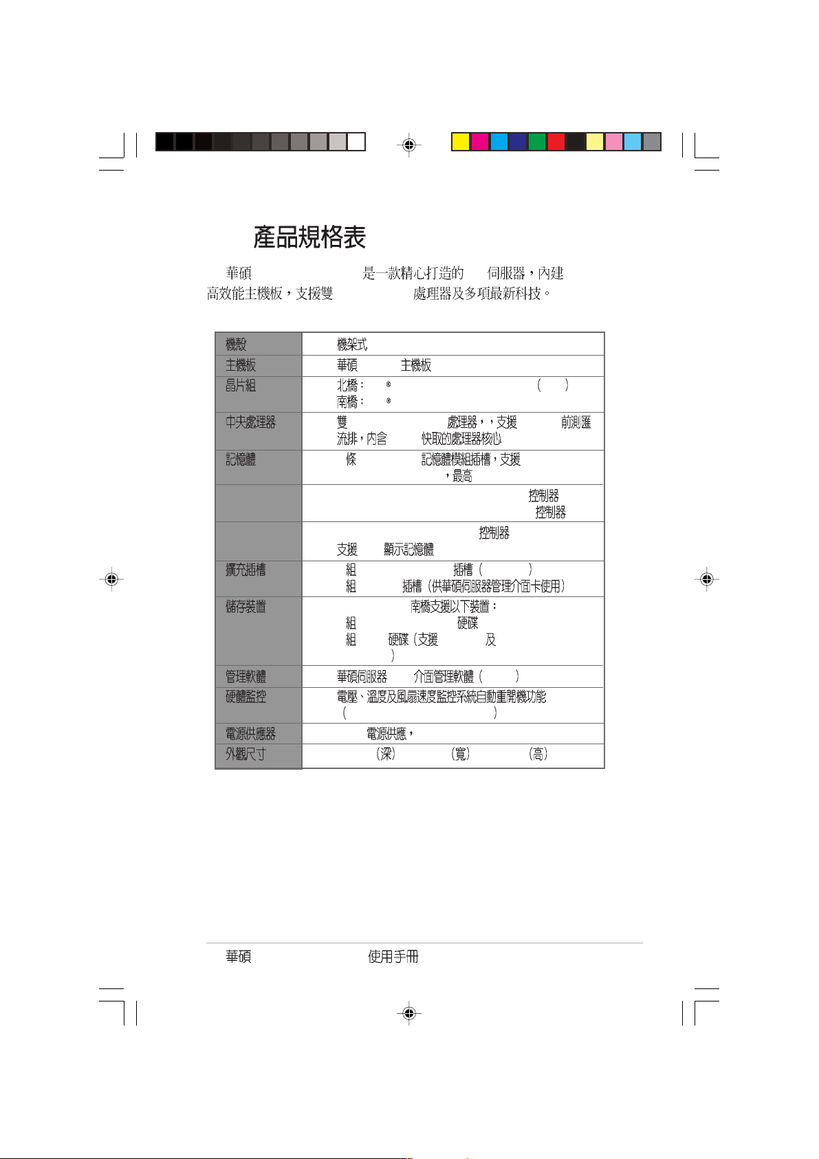
1.1
AP1600R-E2(BA2)
1) AR14 1U
NCLV-D
500W 100V-240V
SATA
SATA 2
2) CPU
3) AC
4)
5)
6)
AP1600R-E2(BA2)
AP1600R-E2(BA2)
ASWM
CA Anti-virus
1-2
1.2
AP1600R-E2(BA2) 1U NCLV-D
Intel® XeonTM
1U (AR14)
NCLV-D
Intel E7320 Memory Controller Hub MCH
Intel 6300ESB
®
Intel
4 184-pin DDR DDR333
registered ECC DIMMs 16GB
LAN Broadcoml® BMC5721 64-bit Gigabit LAN
Broadcoml® BMC5705E 32-bit Gigabit LAN
VGA ATI RAGE-XL PCI-based VGA
8MB
1 PCI-X 64-bit/66MHz PCI-X 1.0
1 Mini-PCI
Intel® 6300ESB
2 Ultra DMA 100/66/33
2 SATA RAID 0/1 Adaptec HostRAID
Technology
TM
Xeon
3.2GHz 800 MHz
L2 1M
Web ASWM
Automatic System Restart, ASR
500W 100V-240V, 50Hz-60Hz
600mm x 445mm x 43.6 mm
AP1600R-E2(BA2)
1-3
1.3
AP1600R-E2(BA2) 1U
Socket 604 Intel XeonTM
L2 1M 4 DDR333
16 GB Gigabit
8MB ATI RAGE-XL VG A 1 PCI-X 64-bit/66MHz
1 Mini-PCI
AP1600R-E2(BA2)
Microsoft Windows® 2003
Server Windows® 2000 Server Windows® 2000 Advance Server
RedHat Linux® 9.0 SuSE Linux® 8.2 Novell Netware 6.x
AP1600R-E2(BA2)
19
AP1600R-E2(BA2)
LED
1-4
1.4
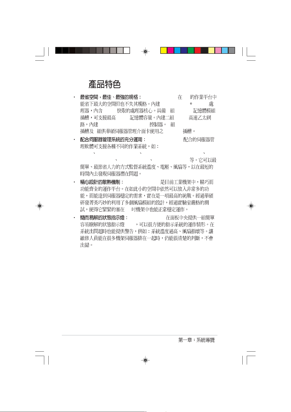
AP1600R-E2(BA2)
1.5
AP1600R-E2(BA2)
LED Location USB
USB
AP1600R-E2(BA2)
2
1
1. AC
2.
3. PS/2
4. PS/2
5. USB2.0
6. COM1
AP1600R-E2(BA2)
3
4
6
5
8
7
7.
8. RJ45 Gigabit LAN 1
9. RJ45 Gigabit LAN 2
10.
11. PCI
109
11
Broadcom BCM5720
Broadcom BCM5705E
1-5
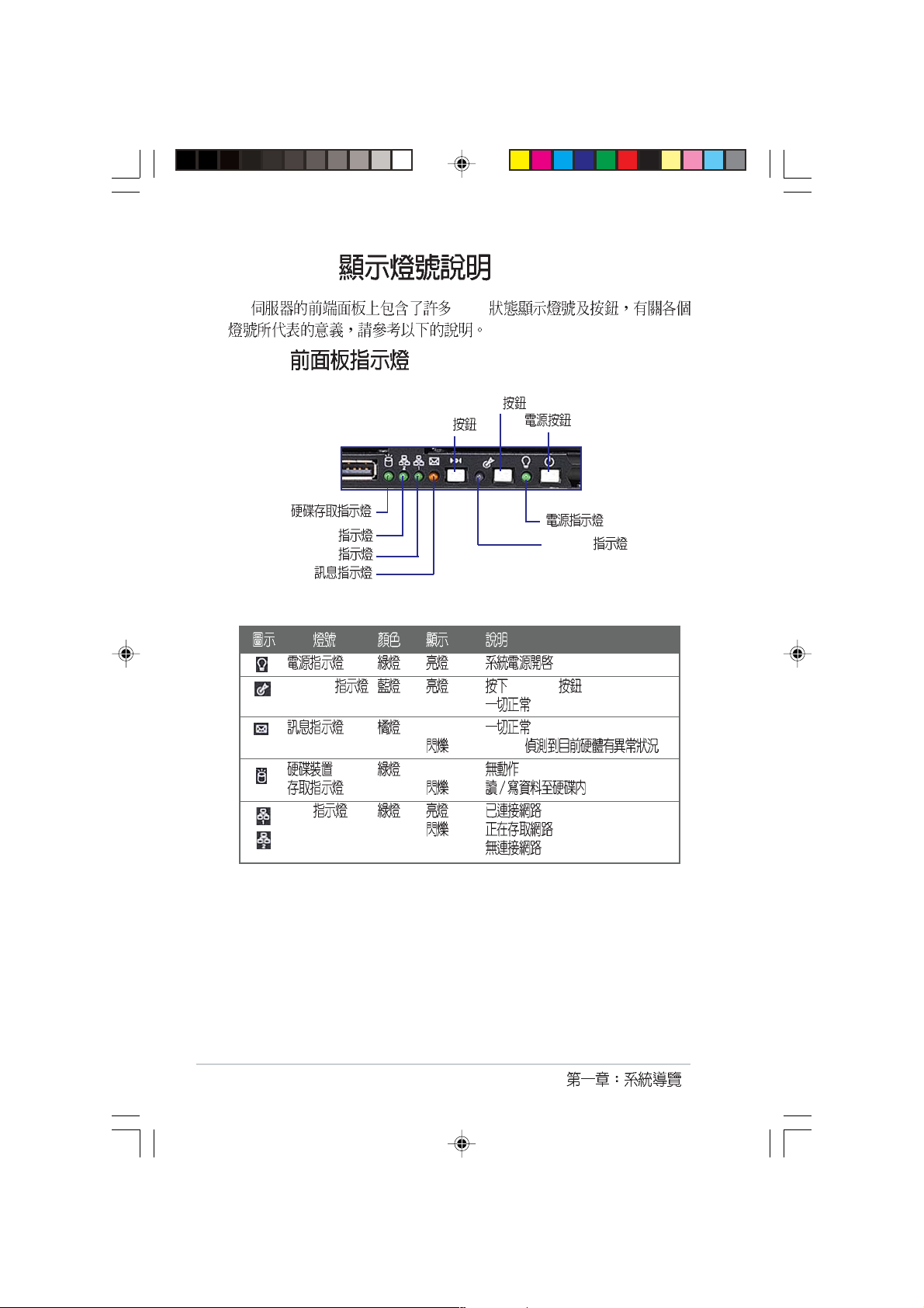
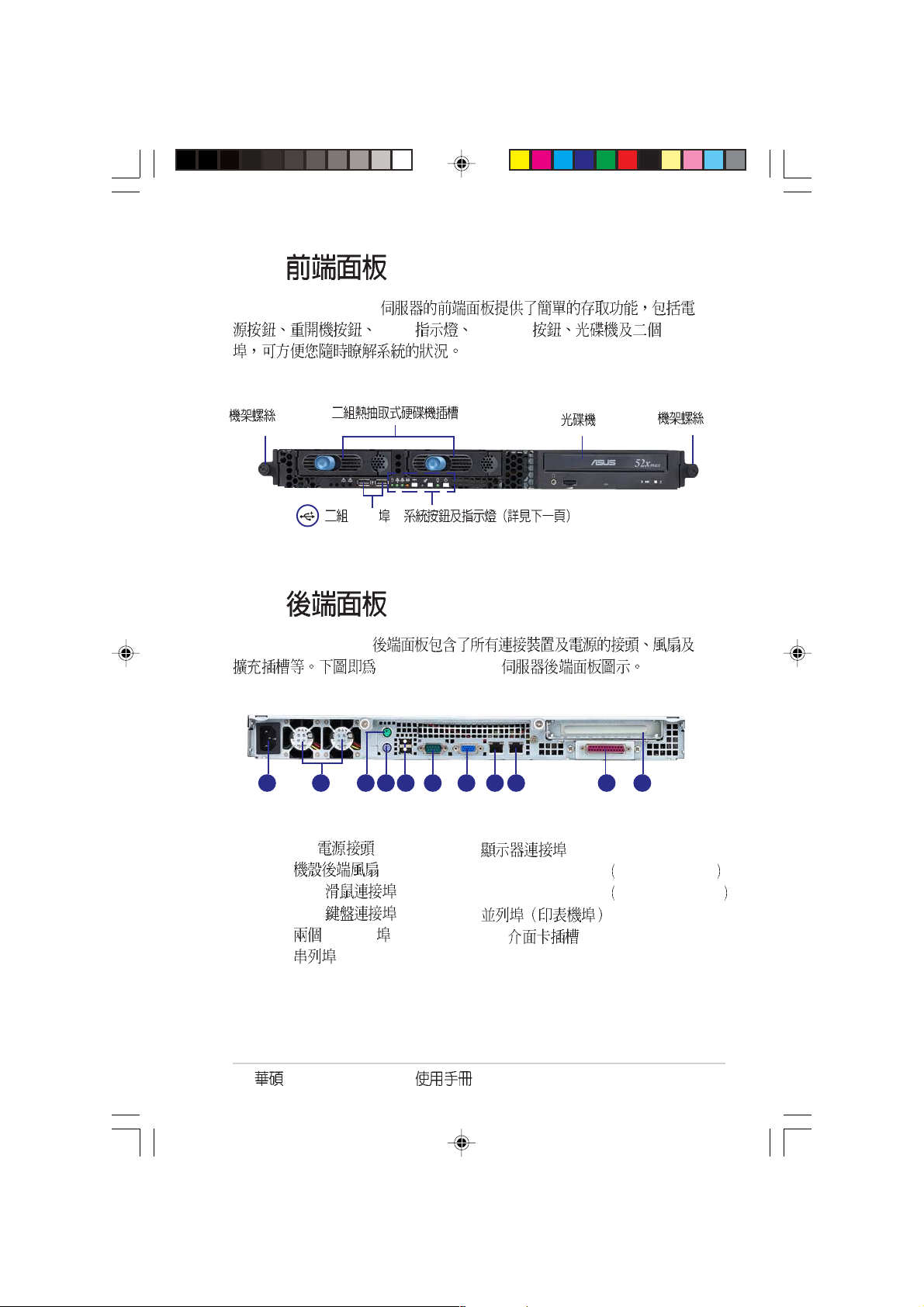
1.6 LED
1.6.1
LED
Location
Reset
LAN2
LAN1
LED
Location Location
OFF
OFF
ASWM
OFF
LAN
OFF
Location
1-6
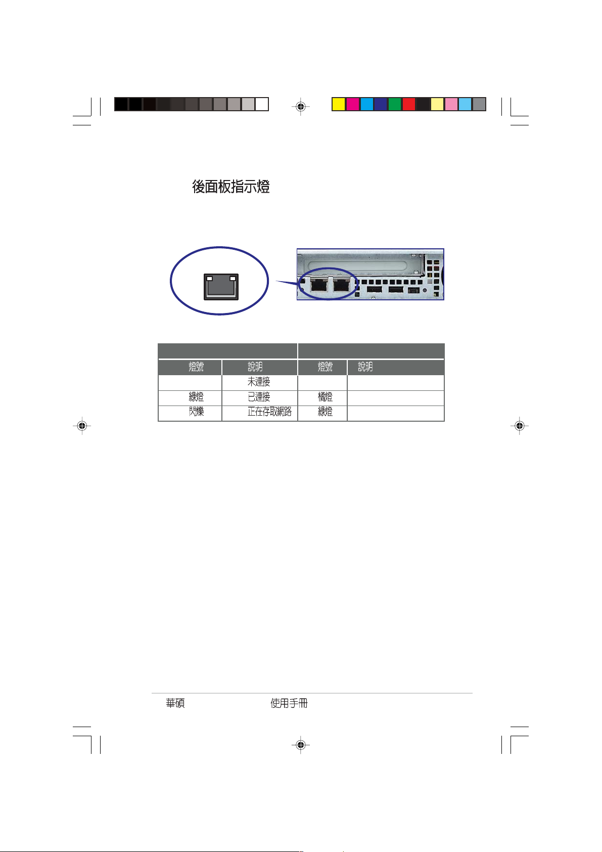
1.6.2
RJ-45
SPEEDACT/LNK
ACT/LINK LED SPEED LED
OFF OFF 10Mbps
100Mbps
1000Mbps
AP1600R-E2(BA2)
1-7
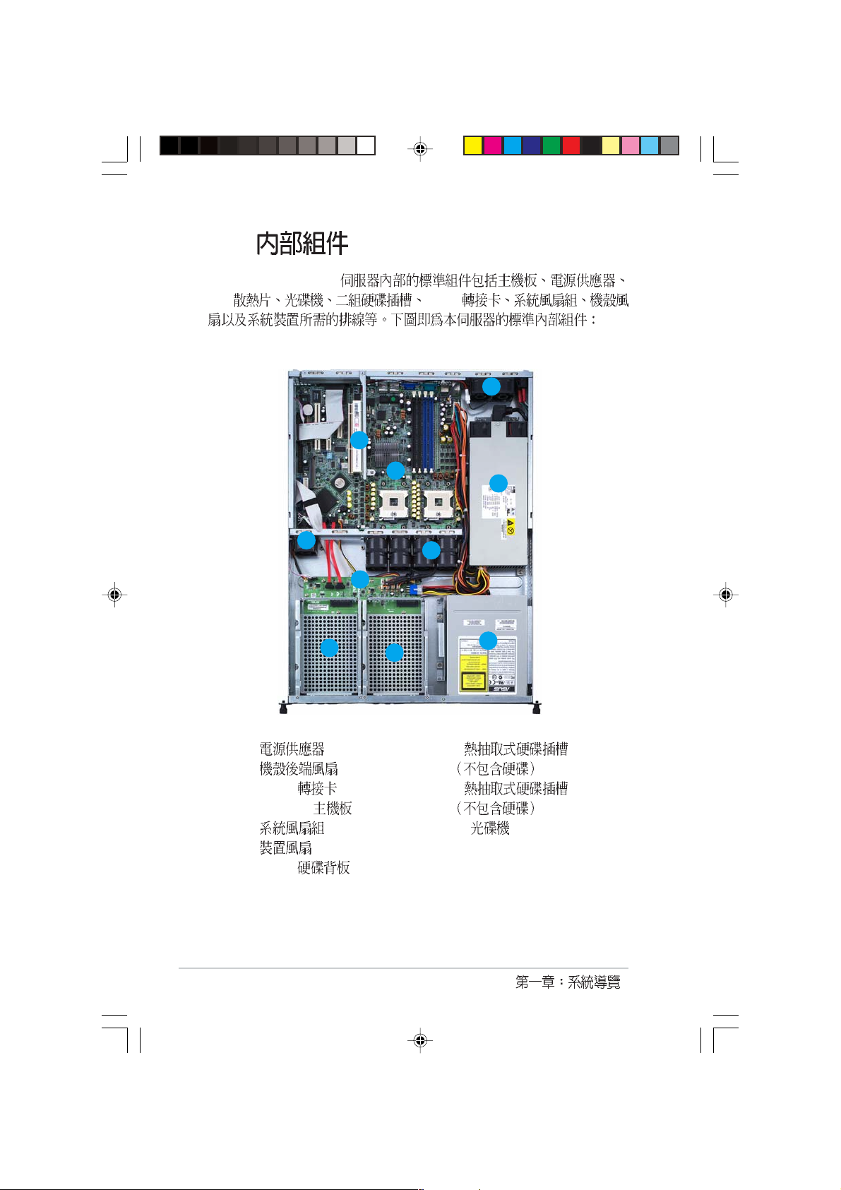
1.7
AP1600R-E2(BA2)
CPU PCI-X
3
2
6
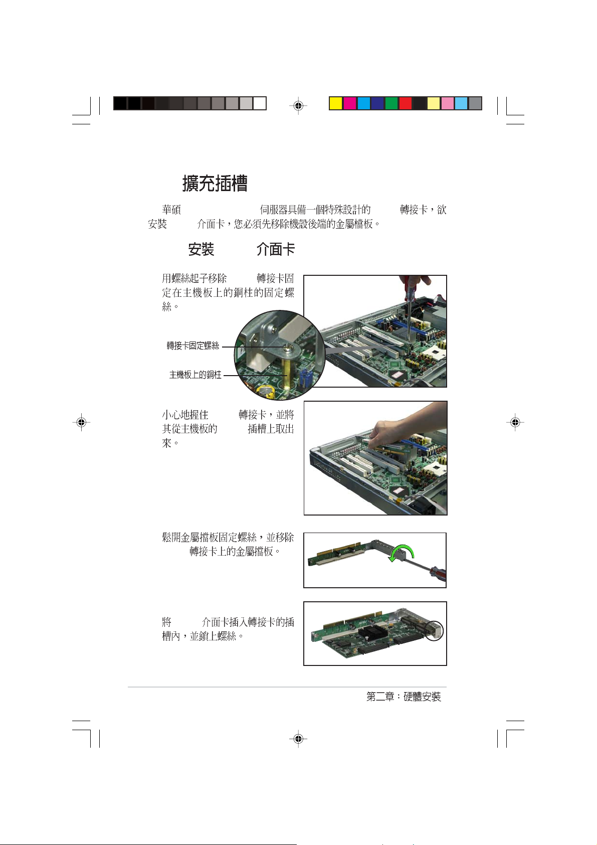
1.
2.
3. PCI-X
4. NCLV-D
5.
6.
7. SATA
4
5
7
8
9
1
10
8. 1
9. 2
10.
1-8

AP1600R-E2(BA2)
2.1
AP1600R-E2(BA2)
1.
2.
3.
4.
5.
2-2
2.2
2.2.1
1.
2.
AP1600R-E2(BA2)
3.
4.
AP1600R-E2(BA2)
2-3
2.2.2
1.
2-4
2.
3.
4.
2.3 CPU
AP1600R-E2(BA2) NCLV-D 604
ZIF XeonTM
L2 512K L3 1M Intel
NetBurstTM
NCLV-D
®
(CPU1)
(CPU2)
NCLV-D CPU Socket 604
1.
2. CPU CPU
CPU 1
2.3.1 CPU
CPU
CPU
Intel Xeon
Gold Arrow
Pin A1
CPU
1.
2. CPU
AP1600R-E2(BA2)
2-5
2.3.2
1.
2.
CPU 1
2-6
3.
4.
2.3.3 CPU
1. CPU CPU 1
2.
3.
CPU
4.
AP1600R-E2(BA2)
2-7
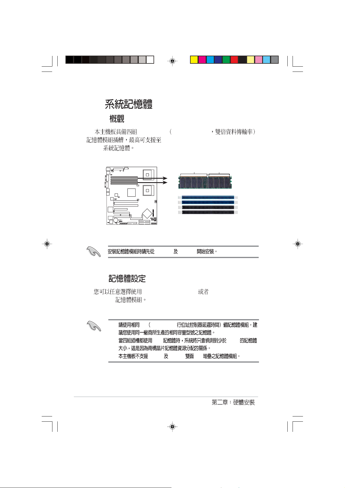
2.4
2.4.1
DIMM
DDR DIMM Double Data Rate
16GB 184-pin registered ECC DDR 333
NCLV-D 184-Pin DDR DIMM sockets
2.4.2
DDR DIMM
1. CL CAS-Latency
NCLV-D
80 Pins104 Pins
DDR_B2 DDR_A2
256, 512MB,1GB,2GB 4GB registered ECC
DDR_B2
DDR_A2
DDR_B1
DDR_A1
2-8
2. 4GB 16GB
3. 128MB 256 MB x16
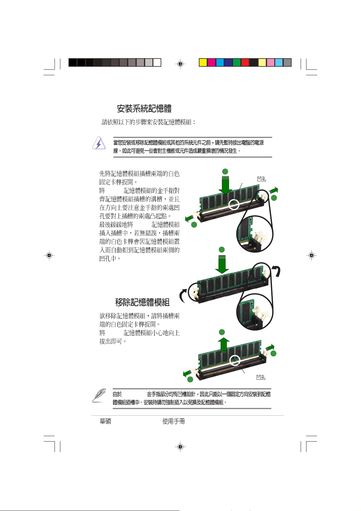
2.4.3
1.
2. DDR
3. DDR
2.4.4
1.
2. DDR
2
DDR DIMM
1
1
3
3
DDR DIMM
AP1600R-E2(BA2)
1
1
DDR DIMM
2-9
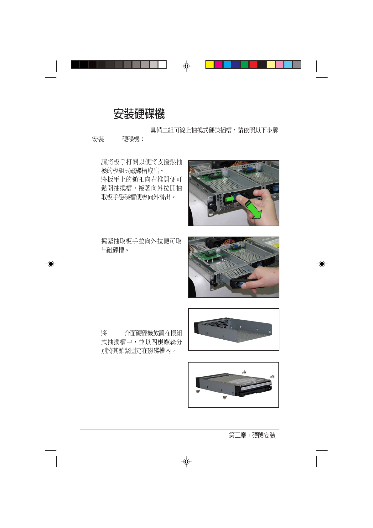
2.5
AP1600R-E2(BA2)
SATA
1.
2.
3.
4. SATA
2-10
5.
SATA
6.
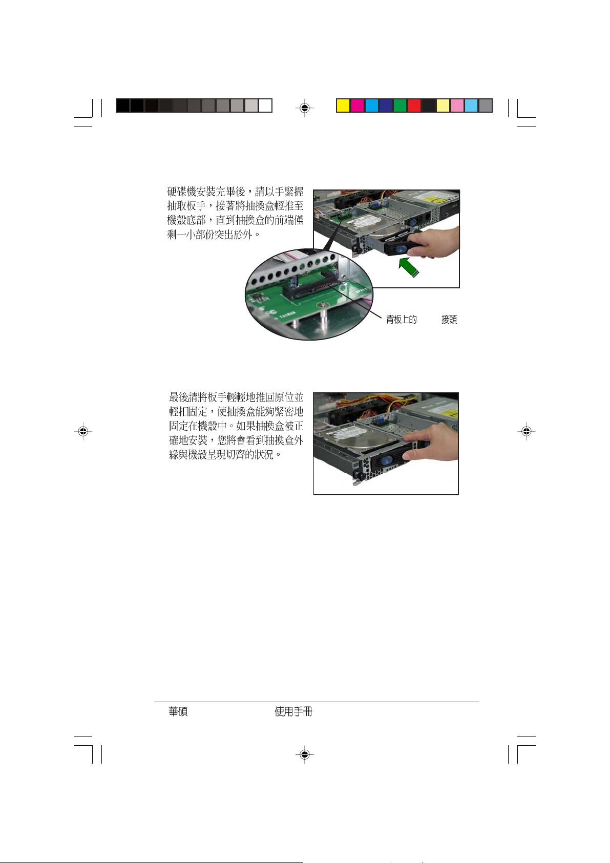
AP1600R-E2(BA2)
2-11
2.6
AP1600R-E2(BA2) PCI-X
PCI-X
2.6.1 PCI-X
1. PCI-X
2. PCI-X
PCI-X
3.
4. PCI-X
2-12
PCI-X

5. PCI-X
6. PCI-X
PCI-X
7. PCI-X
8.
PCI-X
AP1600R-E2(BA2)
PCI-X
2-13

2.6.2
1. BIOS
BIOS
2. IRQ
3.
IRQ
01
12
2 N/A
3* 11 COM 2
4* 12 COM 1
5* 13 LPT 2
614
7* 15 LPT 1
83 CMOS/
9* 4 ACPI
10* 5 PCI
11* 6 PCI
12* 7 PS/2
13 8
14* 9 IDE
15* 10 IDE
*
INTA# INTB# INTC# INTD# REQ# GNT#
AIC-8130 PXIRQ2 - - - X_REQ3 X_GNT3
ATI Rage XL PIRQB# - - - REQ2# BNT2#
BCM5705E PIRQF# - - - REQ3# GNT3#
PCI-X 1(64-bit) PXIRQ0 PXIRQ1 PXIRQ2 PXIRQ3 X_REQ0 X_GNT0
PCI
IRQ IRQ IRQ
2-14

2.7
AP1600R-E2(BA2)
11
2
1
5
6
7
8
3
4
9
10
1. ( )
2. ( )
3. 24-pin SSI ( )
4. 8-pin SSI ( )
5. Secondary IDE ( )
6. ( SATA )
7. SATA ( SATA )
8. ( SATA )
9. SATA ( SATA )
10. 4-pin ( )
11. SMBus ( SATA )
AP1600R-E2(BA2)
2-15

2.8
1.
2.
3.
4.
5.
2.8.1
1.
2.
3.
2-16
2.8.2
1.
2.

2.8.3
1.
2.
3.
AP1600R-E2(BA2)
2-17

2.8.4
2.8.4.1
1.
2.
2-18
3.

2.8.4.2
1.
2.
5.25
3.
AP1600R-E2(BA2)
2-19

2.8.5
2.8.5.1
1. 2.7
2. CPU PCI
DDR
3.
PCI
4.
2-20
5.

2.8.5.2
1.
2. IO
3. 7
NCLV-D
4. PCI-X
5.
2.7
6.
CPU PCI
DDR
AP1600R-E2(BA2)
2-21

2.9 SATA
SATA
SMBus
SATA
SATA
FAN1
CPU_FAN1
8-pin
2-22

(BA2)
AP1600R-E2

3.1
3.2
AP1600R-E2(BA2)
8
1.
2.
3. 2
3-2
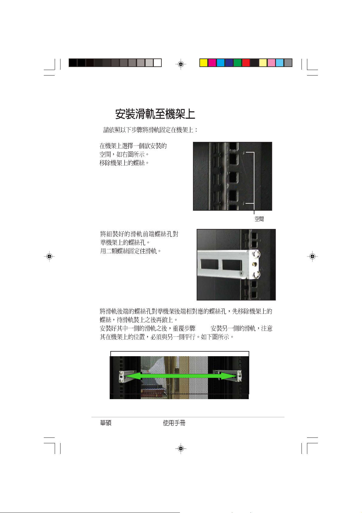
3.3
1. 1U
2.
3.
4.
1U
5.
6. 1~5
AP1600R-E2(BA2)
3-3

3.4
1.
2.
3-4

Jumper

4.1
PS/2KBMS
T: Mouse
B: Keyboard
USB12
VGA
KBPWR1
COM1
SSIPWR1
REAR_FAN1
USBPW12
SSI12V1
PSUSMB1
DDR DDR_B2 (64 bit,184-pin module)
DDR DDR_A2 (64 bit,184-pin module)
DDR DDR_B1 (64 bit,184-pin module)
DDR DDR_A1 (64 bit,184-pin module)
26.8cm (10.5in)
NCLV-D
CPU_FAN1
CPU1
mPGA 604
LAN1
LAN2
RAGE XL
Controller
CLRTC1
VGA
Super
I/O
ATI
8Mbit
Flash
BIOS
Gigabit
LAN
BCM5705E
LAN_EN2
Gigabit
BCM5721
VGA_EN1
CR2032 3V
Lithium Cell
CMOS Power
COM2
LAN
REAR_FAN2
PCIE3 (x4 link)
PCI4 (32-bit 5V PCI)
PCI5 (32-bit 5V PCI)
PCI-X PCI-X
LAN_EN1
PCIX1 (64-bit PCI-X)
PCIX2 (64-bit PCI-X)
SB_PWR1
BMCCONN1
BPSMB1
RECOVERY1
LPT1
FLOPPY1
Intel
MCH
E7320
BMCSOCKET1
SEC_IDE1
PRI_IDE1
CPU_FAN2
CPU2
Intel
ICH
6300ESB
AUX_PANEL1
HDLED1
FRNT_FAN1
FRNT_FAN2
SATA2
SATA1
USB34
USBPW34
mPGA 604
30.5cm (12in)
PANEL1
4-2

Jumpers
1. Clear RTC RAM (CLRTC1) 4-4
2. VGA Graphics controller setting (3-pin VGA_EN1) 4-5
3. USB device wake-up (3-pin USBPW12, USBPW34) 4-5
4. Keyboard power (3-pin KBPWR1) 4-6
5. Gigabit LAN controller setting (3-pin LAN_EN1) 4-6
6. Gigabit LAN controller setting (3-pin LAN_EN2) 4-7
7. BIOS Recovery (3-pin RECOVERY1) 4-7
1. Floppy disk drive connector (34-1 pin FLOPPY) 4-8
2. IDE connectors (40-1 pin PRI_IDE1, SEC_IDE1) 4-8
3. Serial ATA connectors (7-pin SATA1, SATA2) 4-9
4. Hard disk activity LED connector (2-pin HDLED1) 4-10
5. System fan connectors (REAR_FAN1/2, FRNT_FAN1/2) 4-10
6. USB connector (10-1 pin USB34) 4-11
7. Serial port connector (10-1 pin COM2) 4-11
8. SSI power connectors
(24-pin EATXPWR1, 8-pin SSI+12V1/+12V2) 4-12
9. Backplane SMBus connector (6-1 pin BPSMB1) 4-13
10. Power Supply SMBus connector (6-1 pin PSUSMB1) 4-13
11. Parallel port connector (26-1 pin LPT1) 4-14
12. BMC connector (16-pin BMCCONN1) 4-14
13. System panel auxiliary connector (20-pin AUX_PANEL1) 4-15
LAN1 Link activity LED (2-pin LAN1_LINKACTLED)
LAN2 Link activity LED (2-pin LAN2_LINKACTLED)
Locator LED 1 (2-pin LOCATORLED1)
Locator LED 2 (2-pin LOCATORLED2)
Locator Button/Switch (2-pin LOCATORBTN)
Front Panel System Bus (6-1 pin)
14. System panel connector (20-pin PANEL1) 4-16
System power LED (Green 3-pin PLED)
Hard disk drive activity LED (Red 2-pin IDE_LED)
System warning speaker (Orange 4-pin SPEAKER)
ATX power button/soft-off button (Yellow 2-pin PWRSW)
Reset button (Blue 2-pin RESET)
AP16000R-E2(BA2)
4-3

4.2
1. CMOS 3-pin CLRTC1
CMOS
CMOS
1
2
3 CLRTC [1-2] [2-3] 5-10
CMOS
4
5
6 <Del> BIOS
BIOS
RTC CLRTC1
4-4
NCLV-D
NCLV-D Clear RTC RAM
RTC BIOS
CLRTC1
3221
Normal
(Default)
C.P.R CPU Parameter Recall
Clear CMOS

2. VGA 3-pin VGA_EN1
ATI Rage XL
[1-2]
NCLV-D
VGA_EN1
NCLV-D VGA Setting
1
2
Enable
(Default)
2
3
Disable
3. USB 3-pin USBPW12, USBPW34
+5V USB S1
+5VSB S3 S4
USB
+5V [1-2]
NCLV-D
NCLV-D USB device wake-up
1. USB +5VSB
500mA/+5VSB
2.
+5VSB
AP16000R-E2(BA2)
USBPW12
12
+5V +5VSB
(Default)
USBPW34
12
+5V +5VSB
(Default)
23
23
4-5

4. (3-pin KBPWR1)
[2-3] +5VSB
1 +5VSB ATX
BIOS BIOS
NCLV-D
KBPWR1
12
+5V +5VSB
(Default)
NCLV-D Keyboard power setting
23
5. Gigabit LAN1 (3-pin LAN_EN1)
Broadcom BCM5721 Gigabit
LAN [1-2] Gigabit LAN
4-6
NCLV-D
NCLV-D LAN_EN1 setting
LAN_EN1
21 32
Enable
(Default)
Disable

6. Gigabit LAN2 (3-pin LAN_EN2)
Broadcom BCM5705E Gigabit
LAN [1-2] Gigabit LAN
NCLV-D
LAN_EN2
3
2
Disable
NCLV-D LAN_EN2 setting
2
1
Enable
(Default)
7. BIOS 3-pin RECOVERY1
BIOS
BIOS
1 [1-2] [2-3]
2 BIOS support CD
BIOS
3 [2-3] [1-2]
4
5 <Del> BIOS BIOS
NCLV-D
NCLV-D BIOS recovery setting
AP16000R-E2(BA2)
RECOVERY1
1
2
Normal BIOS Recovery
(Default)
2
3
4-7

4.3
1. 34-1 pin FLOPPY1
NCLV-D
FLOPPY
PIN 1
NOTE: Orient the red markings on
the floppy ribbon cable to PIN 1.
NCLV-D Floppy disk drive connector
2. IDE 40-1 pin PRI_IDE1 SEC_IDE1
Ultra DMA 100/66 IDE
IDE CD-ROM
Slave
4-8
1. IDE UltraDMA
2. UltraDMA 100/66 IDE
80 IDE
NCLV-D
SEC_IDE1
PIN 1
PRI_IDE1
PIN 1
NOTE: Orient the red markings
(usually zigzag) on the IDE
ribbon cable to PIN 1.
NCLV-D IDE connectors

3. Serial ATA 7-pin SATA1, SATA2
Serial ATA Serial ATA
150MB 133MB
Parallel ATA Ultra ATA/133
NCLV-D
SATA2
GND
RSATA_TXP2
RSATA_TXN2
GND
RSATA_RXP2
RSATA_RXN2
GND
SATA1
GND
RSATA_TXP1
RSATA_TXN1
GND
RSATA_RXP1
RSATA_RXN1
NCLV-D SATA connectors
Serial ATA
Serial ATA
Parallel ATA
RAID 0 RAID1 Serial ATA RAID
Serial ATA Windows XP Service Pack 1
Windows 2000 Service Pack 4 Serial ATA RAID
RAID0 RAID1 Win 2000/XP
GND
Serial ATA
Serial ATA
SATA1 Master
SATA2 Slave
AP16000R-E2(BA2)
4-9

4. IDE 4-pin HDLED1
SCSI IDE_LED
NCLV-D
HDLED1
1
SCSI_ACTLED-
SCSI_ACTLED-
SCSI_ACTLED+
SCSI_ACTLED+
NCLV-D
SCSI/SATA card activity LED connector
5. 3-pin REAR_FAN1/2 , FRNT_FAN1/2
350 740 8.88 2.1 4.44
53.28 /+12
+12V
GND
4-10
NCLV-D
NCLV-D Fan connectors
REAR_FAN1
REAR_FAN2
FRNT_FAN1
FRNT_FAN2
REAR_FAN2REAR_FAN1
GND
Rotation
GND
+12V
Rotation
+12V
FRNT_FAN1 FRNT_FAN2
GND
+12V
Rotation
GND
+12V
Rotation

6. USB 10-1 pin USB56,USB78
USB USB 2.0
480 Mbps USB 1.1 12 Mbps 40
NCLV-D
USB34
NCLV-D USB 2.0 connector
1394 USB
7. COM2 10-1 pin COM2
USB+5V
USB_P6-
USB_P6+
USB+5V
USB_P5-
USB_P5+
GND
NC
USB+5V
BIOS COM2
COM2 COM2
COM2
NCLV-D
COM2
PIN 1
NCLV-D
Serial port2 (COM2) connector
AP16000R-E2(BA2)
4-11

8. SSI 24-pin EATXPWR1, 8-pin SSI+12V1/+12V2
SSI
24
8-pin +12V
SSI 12V 2.0 450W
8-pin +12V
4-12
NCLV-D
NCLV-D Power connectors
24-pin Power Connector
+3 Volts
+3 Volts
Ground
+5 Volts
Ground
1
Ground
Ground
PSON#
+3 Volts
-12 Volts
+5 Volts
Ground
Ground
Ground
Power OK
+5V Standby
-5 Volts
+5 Volts
+12 Volts
+5 Volts
+12 Volts
+5 Volts
+3 Volts
Ground
For Power Supply
with 20-pin
Power Connector
8-pin
GND+12V2 CPU
GND+12V1 CPU
GND+12V1 CPU
GND+12V2 CPU

9. SMBus 6-1 pin BPSMB1
SMBus System
Management Bus SMBus
NCLV-D
BPSMB1
1
NC
GND
+5V
NCLV-D SMBus connector
I2C_6_CLK#
I2C_6_DATA#
10. SMBus 6-1 pin PSUSMB1
SMBus System
Management Bus SMBus
NCLV-D
+3.3V Remote Sense
NC
PSU_I2CDATA
GND
PSU_I2CCLK
PSUSMB1
NCLV-D Power supply SMBus connector
AP16000R-E2(BA2)
4-13

11. 26-1 pin LPT1
NCLV-D
LPT1
Pin 1
NCLV-D Parallel port connector
12. BMC 16-pin BMCCONN1
management card
NCLV-D
BMCCONN1
NCLV-D BMC connector
STB# AFD#
SPD0 ERROR#
SPD1 PINIT#
SPD2 SLIN#
SPD3 GND
SPD4 GND
SPD5 GND
SPD6 GND
SPD7 GND
ASUS server
+5VSB
+5VSB
BMC SMBCLK
12CCLK1
PSON#
BMC_RST#
PWROK
PSONEN#
+5VSB
12CDATA1
BMC SMBDATA
GND
BMC_SMI#
FP_PWRBTN#
BMC_PRESENT#
+5VSB
ACK# GND
GND
BUSY
PE GND
SLCT
4-14

13. 20-pin AUX_PANEL1
NCLV-D
I2C_4_DATA#LOCATORLED1+
I2C_4_CLK#
GNDGND
NC
AUX_PANEL1
NCLV-D Auxiliary panel connector
3- pin CASEOPEN
LAN1 2-pin LAN1_LINKACTLED
LAN1
PIN1
+5VSB
Chassis Signal
+3VLOCATORLED1-
LAN1_LINKACTLED+LOCATORBTN#
LAN1_LINKACTLED-GND
LAN2_LINKACTLED-LOCATORLED2-
LAN2_LINKACTLED+LOCATORLED2+
LAN2 2-pin LAN2_LINKACTLED
LAN2
Locator LED 1 2-pin LOCATORLED1
Locator1 Location
LAN1 LAN1
Locator LED2 2-pin LOCATORLED2
Locator2 LAN2
Locator 2-pin LOCATORBTN
Location
SMB 6-1 pin FPSMB
SMBus
AP16000R-E2(BA2)
4-15

14. 20-pin PANEL1
NCLV-D
POWERLED+HDLED+
PANEL1
NCLV-D System panel connector
3-1 pin PLED
2-pin IDE_LED
IDE_LED IDE
IDE
GNDHDLED-
POWERLED-
MLED+NMIBTN#
MLED-GND
NCPOWERBTN#
+5VGND
GNDNC
GNDRESETBTN#
SPKROUTGND
4-pin SPEAKER
ATX 2-pin PWRSW
BIOS
2-pin RESET
4-16
Reset

BIOS
BIOS
BIOS
BIOS

5.1 BIOS
BIOS
1. ASUS AFUDOS DOS BIOS
2. ASUS CrashFree BIOS 2 BIOS
BIOS
3. ASUS Update Windows BIOS
1. BIOS
BIOS AFUDOS
BIOS
2. USB
5.1.1
1.
DOS
a. 1.44MB
b. DOS format A:/S Enter
Windows XP
a. 1.44MB
b. Windows /
c. 3 1/2
d. File Format Format 3 1/2
Floppy Disk
e. Create a MS-DOS startup disk
5-2
BIOS

5.1.2 AFUDOS BIOS
AFUDOS DOS BIOS
BIOS AFUDOS BIOS
BIOS
BIOS
BIOS
•
600KB
•
1. AFUDOS afudos.exe
2. DOS
afudos /o[filename]
BIOS
filename
A:\>afudos /oOLDBIOS1.ROM
3. Enter BIOS
A:\>afudos /oOLDBIOS1.ROM
AMI Firmware Update Utility - Version 1.10
Copyright (C) 2002 American Megatrends, Inc. All rights reserved.
Reading flash ..... done
A:\>
BIOS DOS
AP16000R-E2(BA2)
5-3

BIOS
AFUDOS BIOS
1. tw.asus.com BIOS
BIOS
BIOS
2. AFUDOS.EXE BIOS
3. DOS
afudos /i[filename]
filename
BIOS
A:\>afudos /iNCLVD.ROM
4. AFUDOS BIOS
A:\>afudos /iNCLVD.ROM
AMI Firmware Update Utility - Version 1.10
Copyright (C) 2002 American Megatrends, Inc. All rights reserved.
Reading file ..... done
Erasing flash .... done
Writing flash .... 0x0008CC00 (9%)
BIOS
5-4
BIOS

5. BIOS DOS
A:\>afudos /iNCLVD.ROM
AMI Firmware Update Utility - Version 1.10
Copyright (C) 2002 American Megatrends, Inc. All rights reserved.
Reading file ..... done
Erasing flash .... done
Writing flash .... 0x0008CC00 (9%)
Verifying flash .. done
A:\>
5.1.3 CrashFree BIOS 2 BIOS
CrashFree BIOS 2 BIOS
BIOS
BIOS
1.
2.
3.
BIOS
AP16000R-E2(BA2)
BIOS
BIOS
5-5

Bad BIOS checksum. Starting BIOS recovery...
Checking for floppy...
Bad BIOS checksum. Starting BIOS recovery...
Checking for floppy...
Floppy not found!
Checking for CD-ROM...
CD-ROM found.
Reading file “NCLVD.ROM”. Completed.
Start flashing...
BIOS
4. BIOS
5-6
BIOS BIOS
http://tw.asus.com BIOS
BIOS

5.1.4
BIOS
1. BIOS
2. BIOS
3. BIOS BIOS
4. BIOS
5. BIOS
1.
Windows
ISP
2. VX.XX.
XX
3.
BIOS
AP16000R-E2(BA2)
5-7

BIOS
BIOS
1. ASUS ASUSUpdate ASUSUpdate
2. Update
BIOS from the Internet
Next
3. FTP
Auto Select
5-8
Next
BIOS

4. BIOS
Next
5.
BIOS
BIOS
BIOS BIOS
BIOS BIOS
1. ASUS
ASUSUpdate ASUSUpdate
2. Update
BIOS from a file
Next
3. BIOS
4.
BIOS
AP16000R-E2(BA2)
5-9

5.2 BIOS
BIOS Basic Input and Output System
BIOS
BIOS
BIOS
RUN SETUP
BIOS
BIOS
Flash ROM BIOS Flash
ROM
BIOS BIOS
BIOS
CMOS RAM
BIOS
POST Power-On Self Test
Delete Delete
Alt + Delete
5-10
Reset Ctrl +
BIOS
1. BIOS
BIOS
5.7 BIOS Load Setup
Defaults
2. BIOS
3. http://tw.asus.com BIOS
BIOS
BIOS

5.2.1 BIOS
System Time [11:10:19]
System Date [Fri 08/06/2004]
Legacy Diskette A [1.44M, 3.5 in]
Primary IDE Master : [ST320413A]
Primary IDE Slave : [ASUS CD-S520/A]
Secondary IDE Master : [Not Detected]
Secondary IDE Slave : [Not Detected]
Third IDE Master : [Not Detected]
Fourth IDE Master : [Not Detected]
IDE Configuration
System Information
5.2.2
BIOS
Main
Advanced
Power
Boot
Exit BIOS
Use [ENTER], [TAB] or
[SHIFT-TAB] to select
a field.
Use [+] or [-] to
configure the System
time.
5.2.3
AP16000R-E2(BA2)
5-11

5.2.4
Main
Advanced Power Boot Exit
5.2.5
5.2.6
System Time [11:51:19]
System Date [Thu 05/07 /2004]
Legacy Diskette A [1.44M, 3.5 in]
Primary IDE Master :[ST320413A]
Primary IDE Slave :[ASUS CD-S520/A
Secondary IDE Master :[Not Detected]
Secondary IDE Slave :[Not Detected]
Third IDE Master :[Not Detected]
Fourth IDE Master :[Not Detected]
IDE Configuration
System Information
Enter
Advanced PCI/PnP Settings
WARNING: Setting wrong values in
below sections may cause system to
malfunction.
Plug And Play O/S [No]
PCI Latency Timer [64]
Allocate IRQ to PCI VGA [Yes]
Palette Snooping [Disabled]
PCI IDE BusMaster [Enabled]
Use [ENTER],
[TAB] or [SHIFTTAB] to select a
field.
Use [+] or [-] to
configure the
System time.
5.2.7
5.2.8
5.2.9
5-12
Enter
PageUp PageDown
BIOS

5.3 Main Menu
BIOS
5.2.1 BIOS
System Time [11:10:19]
System Date [Fri 08/06/2004]
Legacy Diskette A [1.44M, 3.5 in]
Primary IDE Master : [ST320413A]
Primary IDE Slave : [ASUS CD-S520/A]
Secondary IDE Master : [Not Detected]
Secondary IDE Slave : [Not Detected]
Third IDE Master : [Not Detected]
Fourth IDE Master : [Not Detected]
IDE Configuration
System Information
Use [ENTER], [TAB] or
[SHIFT-TAB] to select
a field.
Use [+] or [-] to
configure the System
time.
5.3.1 System Time [XX:XX:XXXX]
00 23 00 59 00 59 Tab
Tab + Shift
5.3.2 System Date [Day XX/XX/XXXX]
1 12 1 31 2099 Tab Tab
+ Shift
5.3.3 Legacy Diskette A [1.44M, 3.5 in.]
[Disabled] [360K, 5.
25 in.] [1.2M, 5.25 in.] [720K, 3.5 in.] [1.44M, 3.5 in.] [2.88M, 3.5 in.]
AP16000R-E2(BA2)
5-13

5.3.4 IDE Primary, Secondary,
Third and Fourth IDE Master/Slave
BIOS IDE
IDE
Enter
Primary IDE Master
Device : Hard Disk
Vendor : ST320413A
Size : 20.0GB
LBA Mode : Supported
Block Mode : 16 Sectors
PIO Mode : Supported
Async DMA : MultiWord DMA-2
Ultra DMA : Ultra DMA-5
SMART Monitoring : Supported
Type [Auto]
LBA/Large Mode [Auto]
Block(Multi-sector Transfer)[Auto]
PIO Mode [Auto]
Smart Monitoring [Auto]
32Bit Data Transfer [Disabled]
Select the type of
device connected to
the system.
Device Vendor Size LBA Mode Block
Mode PIO Mode Async DMA Ultra DMA SMART monitoring
BIOS N/A
Type [Auto]
IDE Auto
IDE CDROM IDE
ARMD ATAPI IDE
ZIP LS-120 MO [Not
Installed] [Auto] [CDROM] [ARMD]
LBA/Large Mode [Auto]
LBA [Auto]
LBA LBA
[Disabled] [Auto]
Block (Multi-sector Transfer) [Auto]
[Disabled]
[Disabled] [Auto]
5-14
[Auto]
BIOS

PIO Mode [Auto]
PIO [Auto] [0] [1] [2] [3] [4]
DMA Mode [Auto]
DMA [Auto] [SWDMA0] [SWDMA1] [SWDMA2]
[MWDMA0] [MWDMA1] [MWDMA2] [UDMA0] [UDMA1] [UDMA2]
[UDMA3] [UDMA4] [UDMA5] [UDMA6]
SMART Monitoring [Auto]
Smart Monitoring, Analysis,
and Reporting Technology [Auto] [Disabled] [Enabled]
32Bit Data Transfer [Disabled]
32 [Disabled] [Enabled]
5.3.5 IDE IDE Configuration
IDE
Enter
IDE Configuration
Onboard IDE Operate Mode [Enhanced Mode]
Enhanced Mode Support On [S-ATA]
Configure S-ATA as RAID [No]
IDE Detect Time Out (Sec) [35]
When in AHCI/RAID
mode SATA controller
is forced to Native
mode.
Onboard IDE Operate Mode [Enhanced Mode]
Windows 2000/
XP [Enhanced Mode] [Compatible
Mode] [Enhanced Mode]
Enhanced Mode Support On [S-ATA]
[S-ATA]
ATA ATA
MS-
DOS Windows 98SE/ME ATA
ATA
AP16000R-E2(BA2)
5-15

Configure S-ATA as RAID [No]
S-ATA RAID [No] [Yes]
Onboard IDE Operate Mode [Compatible Mode]
Compatible Mode Option [Primary P-ATA+S-ATA]
IDE SATA [Secondary P-ATA+S-ATA]
[P-ATA Ports Only]
[Primary P-ATA+S-ATA]
[Primary P-ATA+S-ATA] [Secondary P-ATA+S-ATA] [P-ATA Ports Only]
IDE Detect Time Out [35]
ATA/ATAPI
[0] [5] [10] [15] [20] [25] [30] [35]
5.3.6 System Information
BIOS
AMIBIOS
Version : 08.00.10
Build Date : 07/23/04
Processor
Type : Intel(R) Xeon(TM) CPU 2.80GHz
Speed : 2800 MHz
Count : 2
System Memory
Size : 512MB
AMI BIOS
Processor
System Memory
5-16
BIOS
BIOS

5.4 Advanced menu
USB Configuration
MPS Configuration
Remote Access Configuration
CPU Configuration
Chipset
Onboard Devices Configuration
PCI PnP
Configure the USB
support.
5.4.1 USB USB Configuration
USB
USB Configuration
Module Version - 2.23.2-9.4
USB Devices Enabled: None
USB Function [All USB Ports]
Legacy USB Support [Auto]
USB 2.0 Controller [Enabled]
USB 2.0 Controller Mode [HiSpeed]
Enables USB host
controllers.
Module Version USB Devices Enabled
USB USB Devices Enabled None
USB Function [Enabled]
USB [Disabled] [2 USB Ports]
[All USB Ports]
AP16000R-E2(BA2)
5-17

Legacy USB Support [Auto]
USB [Auto]
USB
USB [Disabled]
USB USB
[Disabled] [Enabled] [Auto]
USB 2.0 Controller [Enabled]
USB 2.0 [Disabled]
[Enabled]
USB 2.0 Controller Mode [HiSpeed]
USB 2.0 HiSpeed
480 Mbps Full Speed 12 Mbps [HiSpeed] [Full
Speed]
5.4.2 MPS MPS Configuration
MPS Configuration
MPS Revision [1.4]
MPS Revision [1.4]
5-18
Enables USB host
controllers.
[1.1] [1.4]
BIOS

5.4.3 Remote Access
Configuration
Configure Remote Access type and parameters
Remote Access [Enabled]
Serial port number [COM1]
Serial Port Mode [115200 8,n,1]
Flow Control [None]
Redirection After BIOS POST [Always]
Terminal Type [ANSI]
VT-UTFB Combo Key Support [Disabled]
Remote Access [Enabled]
[Enabled]
Serial port number [COM1]
[COM1] [COM2]
Serial Port Mode [115200 8,n,1]
[115200 8,n,1] [57600 8,n,1]
[38400 8,n,1] [19200 8,n,1] [09600 8,n,1]
Flow Control [None]
Redirection [None]
[Hardware] [Software]
Redirection After BIOS POST [Always]
Enables USB host
controllers.
[Disabled]
Power-On Self-Test (POST)
redirection [Always]
[Disabled] [Boot Loader] [Always]
Terminal Type [ANSI]
[ANSI] [VT100] [VT-UTF8]
VT-UTF8 Combo Key Support [Disabled]
VT-UTF8 combo key ANSI VT100
[Disabled] [Enabled]
AP16000R-E2(BA2)
5-19

5.4.4 CPU Configuration
Configure Advanced CPU settings
Manufacturer: Intel
Brand String: Intel(R) Xeon (TM) CPU 2.80GHz
Frequency : 2800 MHz
FSB Speed : 800 MHz
Ratio Status: Unlocked
Ratio Actual Value : 14
Ratio CMOS Setting: [ 8]
Hyper Threading Technology [Enabled]
Max CPUID Value Limit: [Disabled]
Enhanced C1 Control [Auto]
CPU Internal Thermal Control [Auto]
Sets the ratio between
CPU Core Clock and the
FSB Frequency.
NOTE: If an invalid
ratio is set in CMOS
then actual and
setpoint values may
differ.
Ratio CMOS Setting [8]
BIOS <+> <->
CPU Ratio CMOS Setting
Hyper Threading Technology [Enabled]
Hyper Threading
[Disabled] [Enabled] Hyper-Threading
Intel Pentium 4
Max CPUID Value Limit [Disabled]
CPUID
[Enabled] [Disabled] [Enabled]
Enhanced C1 Control [Auto]
C1E CPU
[Auto][Disabled]
CPU Internal Thermal Control [Auto]
Auto CPU [Auto][Disabled]
5-20
BIOS

5.4.5 Chipset
Enter
Advanced Chipset Settings
Warning: Setting wrong values in below sections may
cause system to malfunction.
NorthBridge Configuration
Onboard LAN Boot ROM [Enabled]
Onboard PCI LAN Boot ROM [Enabled]
OnBoard LAN Boot ROM [Enabled]
ROM [Disabled] [Enabled]
Onboard PCI LAN Boot ROM [Enabled]
PCI LAN
Boot ROM [Disabled] [Enabled]
Options for NB.
Boot
AP16000R-E2(BA2)
5-21

North Bridge Configuration
NorthBridge Chipset Configuration
DIMM Speed: DDR 333
Memory Remap Feature [Enabled]
Memory Mirroring / Sparing [Disabled]
DIMM Speed
DIMM
Memory Remap Feature [Enabled]
[Enabled]
Memory Mirroring / Sparing [Disabled]
[Disabled]
[Enabled]
5-22
RAS [Disabled]
BIOS

5.4.6 OnBoard Devices
Configuration
Configure Win627EHF Super IO Chipset
Serial Port1 Address [3F8/IRQ4]
Serial Port2 Address [2F8/IRQ3]
Parallel Port Address [378]
Parallel Port Mode [Normal]
Parallel Port IRQ [IRQ7]
Serial Port1 Address [3F8/IRQ4]
COM 1 [Disabled] [3F8/
IRQ4] [3E8/IRQ4] [2E8/IRQ3]
Serial Port2 Address [2F8/IRQ3]
COM 2 [Disabled] [3F8/
IRQ4] [2F8/IRQ3] [3E8/IRQ4] [2E8/IRQ3]
Parallel Port Address [378]
[278] [3BC]
Enable or disable
Azalia controller.
[Disabled] [378]
ECP Mode DMA Channel [DMA3]
Parallel Port Mode [ECP]
Parallel Port ECP DMA [DMA0] [DMA1] [DMA3]
EPP Version [1.9]
Parallel Port EPP Parallel Port Mode EPP
[1.9] [1.7]
Parallel Port IRQ [IRQ7]
Parallel port IRQ [IRQ5] [IRQ7]
AP16000R-E2(BA2)
5-23

5.4.7 PCI PCI PnP
PCI/PnP PCI/PnP
IRQ DMA
Advanced PCI/PnP Settings
WARNING: Setting wrong values in below sections
may cause system to malfunction.
Plug And Play O/S [No]
PCI Latency Timer [64]
Allocate IRQ to PCI VGA [Yes]
Palette Snooping [Disabled]
PCI IDE BusMaster [Enabled]
OffBoard PCI/ISA IDE Card [Auto]
IRQ-3 assigned to [PCI Device]
IRQ-4 assigned to [PCI Device]
IRQ-5 assigned to [PCI Device]
IRQ-7 assigned to [PCI Device]
IRQ-9 assigned to [PCI Device]
IRQ-10 assigned to [PCI Device]
IRQ-11 assigned to [PCI Device]
IRQ-14 assigned to [PCI Device]
NO: Lets the BIOS
configue all the
devices in the system.
YES: Lets the
operating system
configure Plug and
Play (PnP) devices not
required for boot if
your system has a Plug
and Play operating
system.
Plug and Play O/S [No]
[No] BIOS
[Yes] [No] [Yes]
PCI Latency Timer [64]
PCI [32] [64]
[96] [128] [160] [192] [224] [248]
Allocate IRQ to PCI VGA [Yes]
PCI IRQ
[Yse] BIOS PCI IRQ
[No] [Yes]
Palette Snooping [Disabled]
VGA [Disabled]
[Disabled] [Enabled]
5-24
MPEG
[Enabled]
BIOS

PCI IDE BusMaster [Enabled]
BIOS PCI
IDE [Disabled] [Enabled]
OffBoard PCI/ISA IDE Card [Auto]
PCI IDE PCI
[Auto] [PCI Slot1] [PCI Slot2] [PCI Slot3] [PCI Slot4] [PCI Slot5] [PCI
Slot6]
IRQ-xx assigned to [PCI Device]
[PCI Device] IRQ PCI/PnP
[Reserved] IRQ ISA
[PCI Device] [Reserved]
IRQ-15 assigned to [PCI Device]
DMA Channel 0 [PCI Device]
DMA Channel 1 [PCI Device]
DMA Channel 3 [PCI Device]
DMA Channel 5 [PCI Device]
DMA Channel 6 [PCI Device]
DMA Channel 7 [PCI Device]
Reserved Memory Size [Disabled]
DMA Channel X assigned to [PCI Device]
[PCI Device] DMA channel PCI/PnP
[Reserved] DMA channel legacy ISA
[PCI Device] [Reserved]
Reserved Memory Size [Disabled]
[Disabled] [16k] [32k]
[64k]
AP16000R-E2(BA2)
5-25

5.5 Power menu
APM
ACPI APIC Support [Enabled]
APM Configuration
Hardware Monitor
Select the ACPI state
used for System
Suspend.
5.5.1 ACPI APIC Support [Enabled]
ACPI APIC RSDT
[Disabled] [Enabled]
ACPI APIC support
5-26
BIOS

5.5.2 APM Configuration
APM Configuration
Power Management/APM [Enabled]
Video Power Down Mode [suspend]
Hard Disk Power Down Mode [Suspend]
Suspend Time Out [Disabled]
Throttle Slow Clock Ratio [50%]
Power Button Mode [On/Off]
Restore on AC Power Loss [Power Off]
Power On By PS/2 Keyboard [Disabled]
Power On By PS/2 Mouse [Disabled]
Power On Ring [Disabled]
Power On By PME# [Disabled]
Power On By RTC Alarm [Disabled]
<Enter> to select
whether or not to
restart the system
after AC power loss.
Power Management [Enabled]
[Disabled] [Enabled]
Video Power Down Mode [Suspend]
[Disabled][Standby]
[Suspend]
Hard Disk Power Down Mode [Suspend]
[Standby][Suspend]
[Disabled]
Suspend Time Out [Disabled]
[Disabled] [1
Min] [2 Min] [4 Min][8 Min] [10 Min] [20 Min] [30 Min] [40 Min] [50 Min]
[60 Min]
Throttle Slow Clock Ratio [50%]
throttle [87.5%] [75.
0%] [62.5%] [50.0%] [37.5%] [25.0%] [12.5%]
AP16000R-E2(BA2)
5-27

Power Button Mode [On/Off]
On/Off
[On/Off] [Suspend]
Restore on AC Power Loss [Power Off]
[Power Off]
[Power On]
[Last State]
[Power Off] [Power On] [Last State]
Power On By PS/2 Keyboard [Disabled]
ATX 1 5VSB
[Disabled] [Enabled]
Power On By PS/2 Mouse [Disabled]
[Enabled] PS2
ATX 1 5VSB
[Disabled] [Enabled]
Power On Ring [Disabled]
[Enabled]
[Disabled]
Power On By PME# [Disabled]
[Enabled] PME
[Disabled] [Enabled]
Power On By RTC Alarm [Disabled]
(RTC) [Enabled]
RTC Alarm Date RTC Alarm Hour RTC Alarm Minute RTC
Alarm Second
[Disabled] [Enabled]
5-28
BIOS

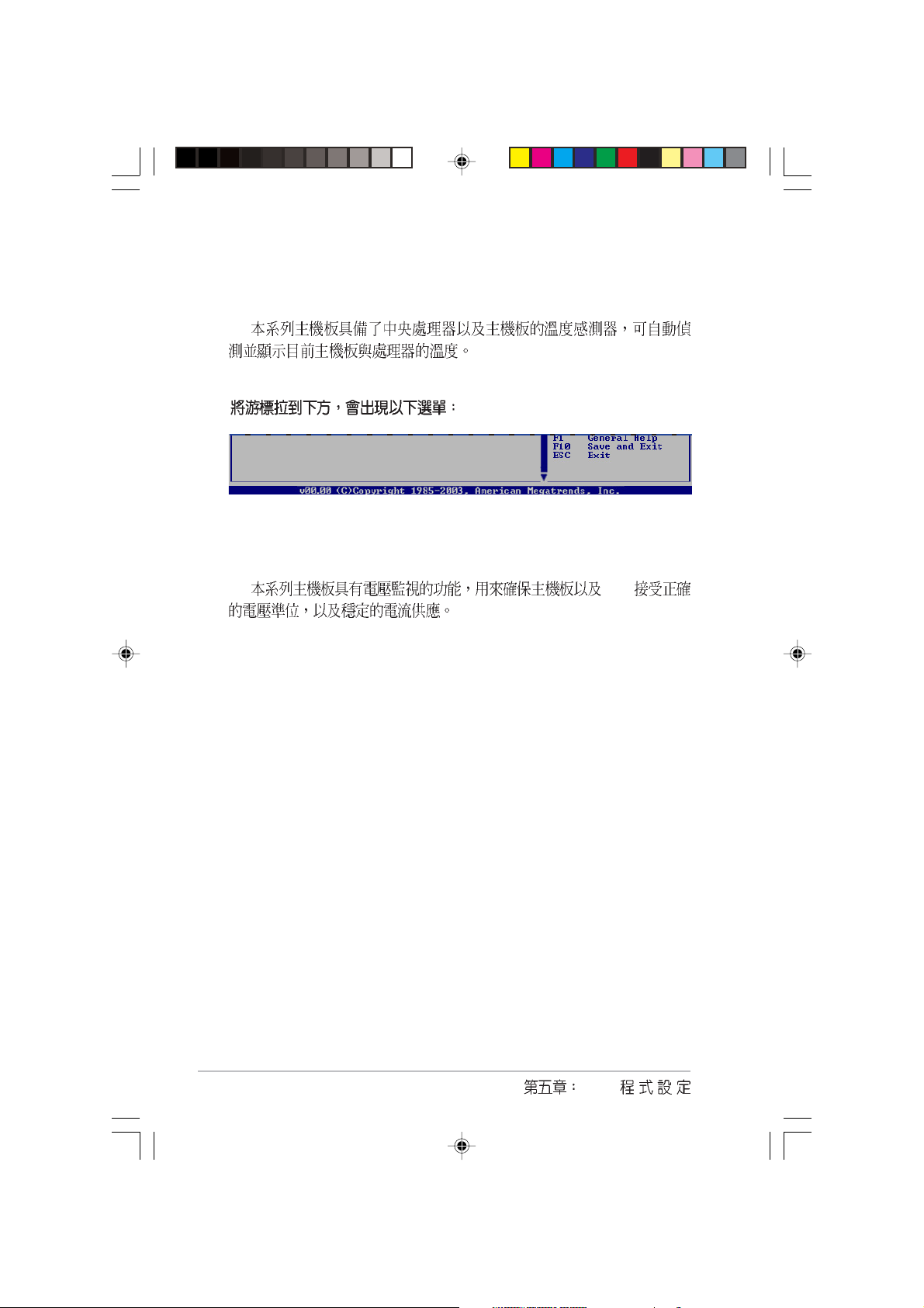
5.5.3 Hardware Monitor
Hardware Monitor
CPU1 Temperature [49ºC/120ºF]
CPU2 Temperature [47ºC/114ºF]
MB Temperature [47ºC/114ºF]
CPU1 Fan Speed [3884RPM]
CPU2 Fan Speed [2871RPM]
Front1 Fan Speed [N/A]
Front2 Fan Speed [N/A]
Rear1 Fan Speed [N/A]
Rear2 Fan Speed [N/A]
Smart Fan Control [Disabled]
VCORE1 Voltage [ 1.320V]
VCORE2 Voltage [ 1.380V]
3.3V Voltage [ 3.345V]
5V Voltage [ 5.094V]
5VSB Voltage [ 5.046V]
CPU1/CPU2 Temperature [xxx /xxx ]
MB Temperature [xxx /xxx ]
CPU1/CPU2 Fan Speed [0]
Front1/Front2 Fan Speed [0]
Rear1/Rear2 Fan Speed [xxxxRPM] or [N/A]
RPM Rotations Per Minute
CPU Fan Speed Front Fan Speed 0
ASUS ASWM
Smart Fan Control [Disabled]
Smart Fan Control [Enabled] CPU1 Temperature CPU2
Temperature Front1 Temperature
AP16000R-E2(BA2)
[Disabled] [Enabled]
5-29
CPU1/CPU2 Temperature [xxx]
Front1 Temperature [xxx]
VBAT Voltage [ 3.088V]
12V Voltage [11.749V]
VCORE1 Voltage, VCORE1 Voltage, 3.3V Voltage, 5V
Voltage, 5VSB Voltage, VBAT Voltage, 12V Voltage
CPU
5-30
BIOS

5.6 Boot menu
APM Configuration
Boot Device Priority
Boot Settings Configuration
Security
Specifies the Boot
Device Priority
sequence
5.6.1 Boot Device Priority
Boot Device Priority
1st Boot Device [1st FLOPPY DRIVE]
2nd Boot Device [PM-ST330620A]
3rd Boot Device [PS-ASUS CD-S360]
4th Boot Device [MBA v7.5.12 Slot 0]
1st~xxth Boot Device [1st Floppy Drive]
1st 2nd
3rd
[xxxxx Drive] [Disabled]
AP16000R-E2(BA2)
USB
5-31

5.6.2 Boot Settings
Configuration
Boot Settings Configuration
Quick Boot [Enabled]
Full Screen Logo [Enabled]
AddOn ROM Display Mode [Force BIOS]
Bootup Num-Lock [On]
PS/2 Mouse Support [Auto]
Wait For ‘F1’ If Error [Enabled]
Hit ‘DEL’ Message Display [Enabled]
Interrupt 19 Capture [Enabled]
Quiet Boot Progress Bar [Disabled]
Allows BIOS to skip
certain tests while
booting. This will
decrease the time
needed to boot the
system.
Select Screen
Select Item
Quick Boot [Enabled]
[Disabled] BIOS
[Disabled] [Enabled]
Full Screen Logo [Enabled]
[Disabled] [Enabled]
MyLogoTM Full Screen Logo
[Enabled]
Add On ROM Display Mode [Force BIOS]
POST
[Enable]
BIOS] [Keep Current]
Bootup Num-Lock [On]
[On]
PS/2 Mouse Support [Auto]
[Enabled] [Auto]
5-32
[Force
NumLock [Off]
PS/2 [Disabled]
BIOS

Wait for F1 If Error [Enabled]
[Enabled]
[F1]
[Disabled] [Enabled]
Hit DEL Message Display [Enabled]
[Enabled] Press DEL
to run Setup [Disabled] [Enabled]
Interrupt 19 Capture [Disabled]
PCI SCSI
Interrupt 19 [Enabled]
[Disabled] [Enabled]
Quiet Boot Progress Bar [Disabled]
POST quiet boot progress bar
[Disabled] [Enabled]
AP16000R-E2(BA2)
5-33

5.6.3 Security
Security Settings
Supervisor Password : Not Installed
User Password : Not Installed
Change Supervisor Password
Boot Sector Virus Protection [Disabled]
<Enter> to change
password.
<Enter> again to
disabled password.
Change Supervisor Password
Not Installed
Installed
Supervisor Password
1. Change Supervisor Password Enter
2. Enter Password
Enter
3. Enter Confirm Password
Password
Installed. Password do not
match!
Supervisor Password Installed
Change Supervisor Word Enter
Password Enter Password
uninstalled.
BIOS CMOS RTC
3.3
5-34
BIOS

Security Settings
Supervisor Password : Installed
User Password : Not Installed
Change Supervisor Password
User Access Level [Full Access]
Change User Password
Clear User Password
Password Check [Setup]
Boot Sector Virus Protection [Disabled]
User Access Level [Full Access]
BIOS
BIOS [No Access] [View Only]
[Limited] [Full Access]
No Access BIOS
View Only BIOS
Limited BIOS
Full Access BIOS
Change User Password
Not Installed Installed
User Password
1. Change User Password [Enter]
2. Enter Password
[Enter]
3. Confirm Password
Password Installed.
Password do not match!
User Password
Installed
AP16000R-E2(BA2)
5-35

Change User Word Enter Password
[Enter] Password uninstalled.
Clear User Password
Password Check [Setup]
[Setup] BIOS BIOS
[Always] BIOS
[Setup] [Always]
Boot Sector Virus Protection [Disabled]
[Enabled]
5.7 BIOS Exit menu
BIOS BIOS
Exit Options
Exit & Save Changes
Exit & Discard Changes
Discard Changes
Load Setup Defaults
[Disabled]
5-36
Esc BIOS
F10 BIOS
BIOS

Exit & Save Changes
BIOS
CMOS Enter [Yes]
CMOS BIOS [No]
BIOS
BIOS Esc BIOS
Discard configuration changes
and exit now? [Yes] BIOS
[No] BIOS
Exit & Discard Changes
BIOS
Enter [OK]
CMOS BIOS
[Cancel] BIOS
Discard Changes
BIOS
Enter [OK]
BIOS [Cancel]
BIOS
Load Setup Defaults
F5 Enter
[Yes] BIOS
[No] BIOS
AP16000R-E2(BA2)
5-37

5-38
BIOS

A

(POST)
1. 115V/230V
2.
3.
4.
1.
2.
A-2
 Loading...