


AP1600R-E2
(AA2/AI2)
1U Rackmount Barebone Server1U Rackmount Barebone Server
1U Rackmount Barebone Server
1U Rackmount Barebone Server1U Rackmount Barebone Server
User Guide

E1962E1962
E1962
E1962E1962
First Edition V1First Edition V1
First Edition V1
First Edition V1First Edition V1
August 2005August 2005
August 2005
August 2005August 2005
Copyright © 2005 ASUSTeK COMPUTER INC. All Rights Reserved.Copyright © 2005 ASUSTeK COMPUTER INC. All Rights Reserved.
Copyright © 2005 ASUSTeK COMPUTER INC. All Rights Reserved.
Copyright © 2005 ASUSTeK COMPUTER INC. All Rights Reserved.Copyright © 2005 ASUSTeK COMPUTER INC. All Rights Reserved.
No part of this manual, including the products and software described in it, may be reproduced,
transmitted, transcribed, stored in a retrieval system, or translated into any language in any form
or by any means, except documentation kept by the purchaser for backup purposes, without the
express written permission of ASUSTeK COMPUTER INC. (“ASUS”).
ASUS provides this manual “as is” without warranty of any kind, either express or implied, including
but not limited to the implied warranties or conditions of merchantability or fitness for a particular
purpose. In no event shall ASUS, its directors, officers, employees, or agents be liable for any
indirect, special, incidental, or consequential damages (including damages for loss of profits, loss of
business, loss of use or data, interruption of business and the like), even if ASUS has been advised
of the possibility of such damages arising from any defect or error in this manual or product.
Specifications and information contained in this manual ae furnished for informational use only, and
are subject to change at any time without notice, and should not be construed as a commitment by
ASUS. ASUS assumes no responsibility or liability for any errors or inaccuracies that may appear in
this manual, including the products and software described in it.
Product warranty or service will not be extended if: (1) the product is repaired, modified or altered,
unless such repair, modification of alteration is authorized in writing by ASUS; or (2) the serial
number of the product is defaced or missing.
Products and corporate names appearing in this manual may or may not be registered trademarks
or copyrights of their respective companies, and are used only for identification or explanation and
to the owners’ benefit, without intent to infringe.
ii

Contents
Notices ............................................................................................... vii
Safety information ............................................................................ viii
About this guide ................................................................................. ix
Chapter 1: Product introductionChapter 1: Product introduction
Chapter 1: Product introduction
Chapter 1: Product introductionChapter 1: Product introduction
1.1 System package contents .................................................... 1-2
1.2 System specifications .......................................................... 1-3
1.3 Front panel features ............................................................. 1-4
1.4 Rear panel features .............................................................. 1-5
1.5 Internal features ................................................................... 1-6
1.6 LED information .................................................................... 1-7
1.6.1 Front panel LEDs .................................................... 1-7
1.6.2 Rear panel LEDs ...................................................... 1-7
Chapter 2: Hardware setupChapter 2: Hardware setup
Chapter 2: Hardware setup
Chapter 2: Hardware setupChapter 2: Hardware setup
2.1 Chassis cover ....................................................................... 2-2
2.1.1 Removing the cover................................................ 2-2
2.1.2 Installing the cover ................................................. 2-3
2.2 Central Processing Unit (CPU) .............................................. 2-4
2.2.1 Installling a CPU ...................................................... 2-4
2.2.2 Installing the CPU heatsink ..................................... 2-6
2.4 System memory ................................................................... 2-7
2.4.1 Overview ................................................................. 2-7
2.4.2 Memory configurations ........................................... 2-7
2.4.4 Removing a DIMM ................................................... 2-8
2.4.3 Installing a DIMM ..................................................... 2-8
2.4 Hard disk drives .................................................................... 2-9
2.4.1 Installing a hot-swap SATA HDD (AA2 model) ....... 2-9
2.4.2 Installing an IDE HDD (AI2 model) ........................ 2-11
2.4.3 Installing an internal SATA HDD (AI2 model) ....... 2-13
2.5 Expansion slot .................................................................... 2-14
2.5.1 Installing an expansion card .................................. 2-14
2.5.2 Configuring an expansion card .............................. 2-16
2.6 Cable connections .............................................................. 2-17
2.7 Removable components ..................................................... 2-19
2.7.1 System fans .......................................................... 2-19
2.7.2 Device fan ............................................................. 2-19
..............................................
.......................
..............................................
............................................................
..............................
............................................................
1-11-1
1-1
1-11-1
2-12-1
2-1
2-12-1
iii

2.7.3 Power supply module ............................................ 2-20
2.7.4 Optical drive ......................................................... 2-21
2.7.5 Motherboard .........................................................2-23
2.8 SATA backplane cabling (for AA2) .................................... 2-26
2.9 Fan control board cabling (for AI2) .................................... 2-27
Chapter 3: Installation optionsChapter 3: Installation options
Chapter 3: Installation options
Chapter 3: Installation optionsChapter 3: Installation options
3.1 Rackmount rail kit items ....................................................... 3-2
3.2 Rack rails assembly .............................................................. 3-2
3.3 Attaching the rails to the rack ............................................. 3-3
3.4 Rackmounting the server ..................................................... 3-4
Chapter 4: Motherboard informationChapter 4: Motherboard information
Chapter 4: Motherboard information
Chapter 4: Motherboard informationChapter 4: Motherboard information
4.1 Motherboard layout .............................................................. 4-2
4.2 Jumpers ................................................................................ 4-5
4.3 Connectors .........................................................................4-10
Chapter 5: BIOS SETUPChapter 5: BIOS SETUP
Chapter 5: BIOS SETUP
Chapter 5: BIOS SETUPChapter 5: BIOS SETUP
5.1 Managing and updating your BIOS ........................................ 5-2
5.1.1 Creating a bootable floppy disk .............................. 5-2
5.1.2 AwardBIOS Flash Utility .......................................... 5-4
5.1.3 ASUS CrashFree BIOS 2 utility ................................ 5-8
5.1.4 ASUS EZ Flash utility ............................................ 5-10
5.1.5 ASUS Update utility ..............................................5-11
5.2 BIOS Setup program ...........................................................5-14
5.2.1 BIOS menu screen ................................................. 5-15
5.2.2 Menu bar ............................................................... 5-15
5.2.3 Navigation keys .................................................... 5-15
5.2.4 General help .......................................................... 5-16
5.2.5 Sub-menu ............................................................. 5-16
5.2.6 Scroll bar .............................................................. 5-16
5.2.7 Pop-up window ..................................................... 5-16
5.3 Main menu .......................................................................... 5-17
5.3.1 Primary IDE Master ............................................... 5-18
5.3.2 Primary IDE Slave .................................................. 5-20
5.3.3 Secondary IDE Master ........................................... 5-20
5.3.4 Secondary IDE Slave ............................................. 5-20
........................................................................
....................................
........................................................................
..................................................
.........................
..................................................
..................................
.................
..................................
3-13-1
3-1
3-13-1
4-14-1
4-1
4-14-1
5-15-1
5-1
5-15-1
iv

5.4 Advanced menu .................................................................. 5-21
5.4.1 Advanced BIOS Features ...................................... 5-22
5.4.2 CPU Configuration ................................................. 5-23
5.4.3 Memory Configuration .......................................... 5-24
5.4.4 Chipset ................................................................. 5-25
5.4.5 Onboard Device .................................................... 5-26
5.4.6 PCIPnP ................................................................... 5-30
5.4.7 USB Configuration ................................................. 5-32
5.5 Power menu ........................................................................ 5-33
5.5.1 APM Configuration ................................................ 5-34
5.5.2 Hardware Monitor ................................................. 5-37
5.6 Boot menu .......................................................................... 5-39
5.6.1 Boot Device Priority .............................................. 5-39
5.6.2 Hard Disk Boot Priority ......................................... 5-40
5.6.3 Removable Device Priority .................................... 5-40
5.6.4 CD-ROM Boot Priority ........................................... 5-41
5.6.5 Boot Settings Configuration .................................5-41
5.6.6 Security ................................................................ 5-43
5.7 Exit menu ........................................................................... 5-45
Chapter 6: Driver installationChapter 6: Driver installation
Chapter 6: Driver installation
Chapter 6: Driver installationChapter 6: Driver installation
6.1 RAID ...................................................................................... 6-2
6.1.1 RAID configurations ................................................ 6-2
6.1.2 Installing hard disk drives ....................................... 6-2
6.1.3 Setting the RAID item in BIOS ................................ 6-3
6.1.4 RAID configuration utility........................................ 6-3
6.1.5 Creating a RAID driver disk ...................................6-21
6.1.6 Installing the Intel® 6300ESB RAID controller
driver .................................................................... 6-22
6.2 LAN .................................................................................... 6-29
6.2.1 Windows® 2000 Server ....................................... 6-29
6.2.2 Windows® 2003 Server ....................................... 6-31
6.2.3 Red Hat® Linux 9.0 .............................................. 6-33
6.3 VGA .................................................................................... 6-34
6.3.1 Windows® 2000 Server ....................................... 6-34
6.3.2 Windows® 2003 Server ....................................... 6-35
6.3.3 Red Hat® Linux 9.0 .............................................. 6-35
......................................................
...........................
......................................................
6-16-1
6-1
6-16-1
v

Notices
Federal Communications Commission StatementFederal Communications Commission Statement
Federal Communications Commission Statement
Federal Communications Commission StatementFederal Communications Commission Statement
This device complies with Part 15 of the FCC Rules. Operation is subject to
the following two conditions:
•
This device may not cause harmful interference, and
•
This device must accept any interference received including interference
that may cause undesired operation.
This equipment has been tested and found to comply with the limits for a
Class A digital device, pursuant to Part 15 of the FCC Rules. These limits
are designed to provide reasonable protection against harmful interference
in a residential installation. This equipment generates, uses and can radiate
radio frequency energy and, if not installed and used in accordance with
manufacturer’s instructions, may cause harmful interference to radio
communications. However, there is no guarantee that interference will not
occur in a particular installation. If this equipment does cause harmful
interference to radio or television reception, which can be determined by
turning the equipment off and on, the user is encouraged to try to correct
the interference by one or more of the following measures:
•
Reorient or relocate the receiving antenna.
•
Increase the separation between the equipment and receiver.
•
Connect the equipment to an outlet on a circuit different from that to
which the receiver is connected.
•
Consult the dealer or an experienced radio/TV technician for help.
WARNING!WARNING!
WARNING! The use of shielded cables for connection of the monitor to
WARNING!WARNING!
the graphics card is required to assure compliance with FCC regulations.
Changes or modifications to this unit not expressly approved by the
party responsible for compliance could void the user’s authority to
operate this equipment.
Canadian Department of Communications StatementCanadian Department of Communications Statement
Canadian Department of Communications Statement
Canadian Department of Communications StatementCanadian Department of Communications Statement
This digital apparatus does not exceed the Class A limits for radio noise
emissions from digital apparatus set out in the Radio Interference
Regulations of the Canadian Department of Communications.
This This
CC
lass lass
AA
This
This This
C
CC
digital apparatus complies with Canadian ICES-003. digital apparatus complies with Canadian ICES-003.
lass
A
digital apparatus complies with Canadian ICES-003.
lass lass
AA
digital apparatus complies with Canadian ICES-003. digital apparatus complies with Canadian ICES-003.
vi

Safety information
Electrical SafetyElectrical Safety
Electrical Safety
Electrical SafetyElectrical Safety
• Before installing or removing signal cables, ensure that the power cables
for the system unit and all attached devices are unplugged.
• To prevent electrical shock hazard, disconnect the power cable from the
electrical outlet before relocating the system.
• When adding or removing any additional devices to or from the system,
ensure that the power cables for the devices are unplugged before the
signal cables are connected. If possible, disconnect all power cables from
the existing system before you add a device.
• If the power supply is broken, do not try to fix it by yourself. Contact a
qualified service technician or your dealer.
Operation SafetyOperation Safety
Operation Safety
Operation SafetyOperation Safety
• Any mechanical operation on this server must be conducted by certified
or experienced engineers.
• Before operating the server, carefully read all the manuals included with
the server package.
• Before using the server, make sure all cables are correctly connected and
the power cables are not damaged. If any damage is detected, contact
your dealer as soon as possible.
• To avoid short circuits, keep paper clips, screws, and staples away from
connectors, slots, sockets and circuitry.
• Avoid dust, humidity, and temperature extremes. Place the server on a
stable surface.
This product is equipped with a three-wire power cable and plug for the
user’s safety. Use the power cable with a properly grounded electrical
outlet to avoid electrical shock.
Lithium-Ion Battery WarningLithium-Ion Battery Warning
Lithium-Ion Battery Warning
Lithium-Ion Battery WarningLithium-Ion Battery Warning
CAUTION!CAUTION!
CAUTION! Danger of explosion if battery is incorrectly replaced.
CAUTION!CAUTION!
Replace only with the same or equivalent type recommended by
the manufacturer. Dispose of used batteries according to the
manufacturer’s instructions.
CD-ROM Drive Safety WarningCD-ROM Drive Safety Warning
CD-ROM Drive Safety Warning
CD-ROM Drive Safety WarningCD-ROM Drive Safety Warning
CLASS 1 LASER PRODUCTCLASS 1 LASER PRODUCT
CLASS 1 LASER PRODUCT
CLASS 1 LASER PRODUCTCLASS 1 LASER PRODUCT
Heavy SystemHeavy System
Heavy System
Heavy SystemHeavy System
CAUTION!CAUTION!
CAUTION! This server system is heavy. Ask for assistance when
CAUTION!CAUTION!
moving or carrying the system.
vii

About this guide
AudienceAudience
Audience
AudienceAudience
This user guide is intended for system integrators, and experienced users
with at least basic knowledge of configuring a server.
ContentsContents
Contents
ContentsContents
This guide contains the following parts:
1.1.
Chapter 1: Product IntroductionChapter 1: Product Introduction
1.
Chapter 1: Product Introduction
1.1.
Chapter 1: Product IntroductionChapter 1: Product Introduction
This chapter describes the general features of the server, including
sections on front panel and rear panel specifications.
2.2.
Chapter 2: Hardware setupChapter 2: Hardware setup
2.
Chapter 2: Hardware setup
2.2.
Chapter 2: Hardware setupChapter 2: Hardware setup
This chapter lists the hardware setup procedures that you have to
perform when installing or removing system components.
3.3.
Chapter 3: Installation optionsChapter 3: Installation options
3.
Chapter 3: Installation options
3.3.
Chapter 3: Installation optionsChapter 3: Installation options
This chapter describes how to install optional components into the
barebone server.
4.4.
Chapter 4: Motherboard informationChapter 4: Motherboard information
4.
Chapter 4: Motherboard information
4.4.
Chapter 4: Motherboard informationChapter 4: Motherboard information
This chapter gives information about the motherboard that comes
with the server. This chapter includes the motherboard layout, jumper
settings, and connector locations.
5.5.
Chapter 5: BIOS informationChapter 5: BIOS information
5.
Chapter 5: BIOS information
5.5.
Chapter 5: BIOS informationChapter 5: BIOS information
This chapter tells how to change system settings through the BIOS
Setup menus and describes the BIOS parameters.
6.6.
Chapter 6: Driver installationChapter 6: Driver installation
6.
Chapter 6: Driver installation
6.6.
Chapter 6: Driver installationChapter 6: Driver installation
This chapter provides instructions for creating and configuring RAID,
and installing the necessary drivers for different system components.
viii

ConventionsConventions
Conventions
ConventionsConventions
To make sure that you perform certain tasks properly, take note of the
following symbols used throughout this manual.
WARNING: WARNING:
WARNING: Information to prevent injury to yourself when trying
WARNING: WARNING:
to complete a task.
CAUTION:CAUTION:
CAUTION: Information to prevent damage to the components
CAUTION:CAUTION:
when trying to complete a task.
IMPORTANT: IMPORTANT:
IMPORTANT: Instructions that you MUST follow to complete a
IMPORTANT: IMPORTANT:
task.
NOTE: NOTE:
NOTE: Tips and information to aid in completing a task.
NOTE: NOTE:
ReferencesReferences
References
ReferencesReferences
Refer to the following sources for additional information, and for product
and software updates.
1.1.
ASUS NCCH-DR motherboard user guideASUS NCCH-DR motherboard user guide
1.
ASUS NCCH-DR motherboard user guide
1.1.
ASUS NCCH-DR motherboard user guideASUS NCCH-DR motherboard user guide
This manual contains detailed information about the ASUS NCCH-DR
motherboard.
2.2.
ASUS Server Web-based Management (ASWM) user guideASUS Server Web-based Management (ASWM) user guide
2.
ASUS Server Web-based Management (ASWM) user guide
2.2.
ASUS Server Web-based Management (ASWM) user guideASUS Server Web-based Management (ASWM) user guide
This manual tells how to set up and use the proprietary ASUS server
management utility.
3.3.
ASUS websitesASUS websites
3.
ASUS websites
3.3.
ASUS websitesASUS websites
The ASUS websites worldwide provide updated information for all
ASUS hardware and software products. Refer to the ASUS contact
information.
ix

x

Chapter 1
This chapter describes the general
features of the chassis kit. It
includes sections on front panel and
rear panel specifications.
ASUS AP1600R-E2 (AA2/AI2)ASUS AP1600R-E2 (AA2/AI2)
ASUS AP1600R-E2 (AA2/AI2)
ASUS AP1600R-E2 (AA2/AI2)ASUS AP1600R-E2 (AA2/AI2)
Product introduction
1-1
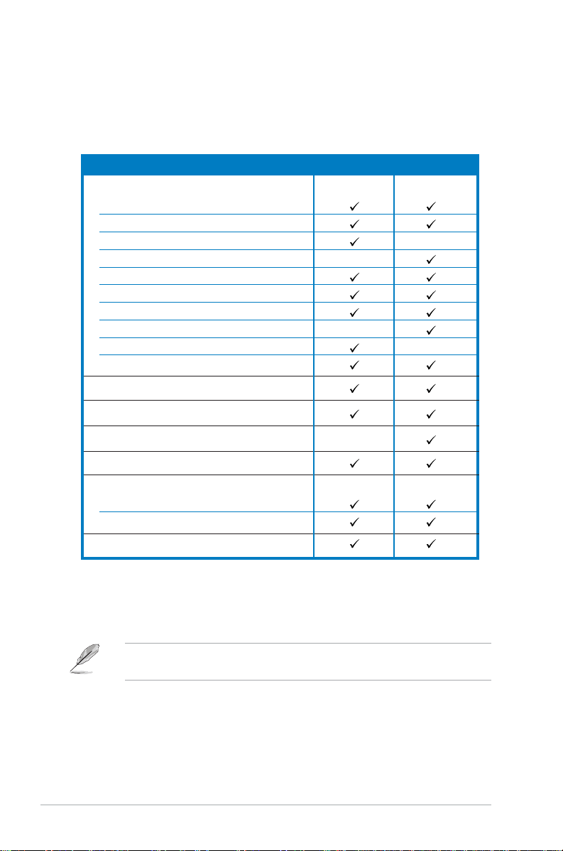
1.1 System package contents
The items in the ASUS AP1600R-E2 (AA2/AI2) product package vary
depending on the model your purchased. Check your package for the
standard items listed in the following table.
Package items AA2 model AI2 model
ASUS AR14 1U rackmount chassis with:
• ASUS NCCH-DR motherboard
• 500W power supply
•SATA backplane
• Fan control board
• Optical drive
• System fan
• Device fan
•2 x internal HDD trays
•2 x hot-swap HDD trays
• Pre-connected device/power cables
CPU heatsink
SA TA cable
IDE cable
Rackmount rail kit
Bundled CDs
• AP1600R-E2 drivers and utilities CD
•CA Anti-virus software CD
User guide
* AA2 model - supports up to two hot-swap SATA hard disks
* AI2 model - supports up to two internal IDE hard disks,
or up to two internal SATA hard disks
Contact your dealer immediately if any of the items is damaged or
missing.
1-21-2
1-2
1-21-2
Chapter 1: Product introductionChapter 1: Product introduction
Chapter 1: Product introduction
Chapter 1: Product introductionChapter 1: Product introduction

1.2 System specifications
The ASUS AP1600R-E2 (AA2/AI2) is a 1U barebone server system
featuring the ASUS NCCH-DR motherboard. The server supports dual Intel
®
Xeon™ processors, and includes the latest technologies through the
chipsets embedded on the motherboard.
ChassisChassis
Chassis Rackmount 1U (AR14)
ChassisChassis
MotherboardMotherboard
Motherboard ASUS NCCH-DR
MotherboardMotherboard
ChipsetChipset
Chipset North Bridge: Intel
ChipsetChipset
ProcessorProcessor
Processor Supports dual Intel
ProcessorProcessor
MemoryMemory
Memory 4 x 184-pin DDR sockets for up to 8 GB system memory
MemoryMemory
LANLAN
LAN Intel
LANLAN
VGAVGA
VGA ATI RAGE-XL PCI-based VGA controller
VGAVGA
Expansion slotsExpansion slots
Expansion slots 1 x PCI-X 66 MHz/64-bit slot (PCI-X 1.0)
Expansion slotsExpansion slots
StorageStorage
Storage Intel
StorageStorage
ManagementManagement
Management ASUS Server Web-based Management (ASWM)
ManagementManagement
Hardware monitorsHardware monitors
Hardware monitors Voltage, temperature, and fan speed monitoring
Hardware monitorsHardware monitors
Power supplyPower supply
Power supply 500W power supply, 115V~230V, 50Hz~60Hz
Power supplyPower supply
DimensionsDimensions
Dimensions 600 mm (l) x 445 mm (w) x 43.6 mm (h))
DimensionsDimensions
South Bridge: Intel® 6300ESB
Threading Technology via two 604-pin sockets
Supports PC3200/PC2700 unbuffered ECC or non-ECC DIMMs
Supports dual-channel memory architecture
®
PRO/1000 CT Network Connection (82547GI)
Intel® PRO/1000 MT Network Connection (82541GI)
Supports 8MB display memory
1 x Mini-PCI socket for the ASUS Server Management Board
®
6300ESB South Bridge supports:
- 2 x Ultra DMA 100/66/33 HDDs
- 2 x SATA HDDs with RAID 0/1 configuration and
Intel® Matrix Storage Technology
Automatic System Restart (ASR) feature
®
E7210 Memory Controller Hub (MCH)
®
Xeon™ 3.4+GHz processors with Hyper-
(IDE model)(IDE model)
(IDE model)
(IDE model)(IDE model)
(SATA model)(SATA model)
(SATA model)
(SATA model)(SATA model)
ASUS AP1600R-E2 (AA2/AI2)ASUS AP1600R-E2 (AA2/AI2)
ASUS AP1600R-E2 (AA2/AI2)
ASUS AP1600R-E2 (AA2/AI2)ASUS AP1600R-E2 (AA2/AI2)
1-31-3
1-3
1-31-3

1.3 Front panel features
The barebone server displays a simple yet stylish front panel with easily
accessible features. The power and reset buttons, LED indicators, location
switch, optical drive, and two USB ports are located on the front panel.
Refer to section “1.6.1 Front panel LEDs” for the LED descriptions.
AA2 modelAA2 model
AA2 model
AA2 modelAA2 model
Rack screwRack screw
Rack screw
Rack screwRack screw
HDD Access LEDHDD Access LED
HDD Access LED
HDD Access LEDHDD Access LED
LAN2 LEDLAN2 LED
LAN2 LED
LAN2 LEDLAN2 LED
LAN1 LEDLAN1 LED
LAN1 LED
LAN1 LEDLAN1 LED
AI2 modelAI2 model
AI2 model
AI2 modelAI2 model
The AA2 and AI2 models have the same front panel features except for
the HDD bays.
Hot-swap HDD baysHot-swap HDD bays
Hot-swap HDD bays
Hot-swap HDD baysHot-swap HDD bays
USB portsUSB ports
USB ports
USB portsUSB ports
Message LEDMessage LED
Message LED
Message LEDMessage LED
Internal HDD baysInternal HDD bays
Internal HDD bays
Internal HDD baysInternal HDD bays
Optical driveOptical drive
Optical drive
Optical driveOptical drive
Power buttonPower button
Power button
Power buttonPower button
Power LEDPower LED
Power LED
Power LEDPower LED
Location switchLocation switch
Location switch
Location switchLocation switch
Location LEDLocation LED
Location LED
Location LEDLocation LED
Reset buttonReset button
Reset button
Reset buttonReset button
Rack screwRack screw
Rack screw
Rack screwRack screw
1-41-4
1-4
1-41-4
Chapter 1: Product introductionChapter 1: Product introduction
Chapter 1: Product introduction
Chapter 1: Product introductionChapter 1: Product introduction

1.4 Rear panel features
The rear panel includes the expansion slot, system power socket, and rear
fans. The middle part includes the I/O shield with openings for the rear
panel connectors on the motherboard.
The ports for the PS/2 keyboard, PS/2 mouse, USB, VGA, and Gigabit
LAN do not appear on the rear panel if motherboard is not present.
A
A
A
A
A
C
C
C
C
C
p
p
p
p
p
o
o
o
o
o
w
w
w
w
w
e
e
e
e
e
r
r
r
r
r
s
s
s
s
s
o
o
o
o
o
c
c
c
c
c
k
k
k
k
k
e
e
e
e
e
t
t
t
t
t
R
R
R
PS/2 mouse port
R
R
PS/2 mouse portPS/2 mouse port
PS/2 mouse portPS/2 mouse port
e
e
e
e
e
a
a
a
a
a
r
r
r
r
r
f
f
f
f
f
a
a
a
a
a
n
n
n
n
n
s
s
s
s
s
U
U
PS/2 keyboard port
U
U
U
PS/2 keyboard portPS/2 keyboard port
PS/2 keyboard portPS/2 keyboard port
S
S
S
S
S
B
B
B
B
B
p
p
p
p
p
o
o
o
o
o
r
r
r
r
r
t
t
t
t
t
s
s
s
s
s
Refer to section “1.6.2 Rear panel LEDs” for the LED descriptions.
V
V
V
V
V
S
S
S
S
S
e
e
e
e
e
r
r
r
r
r
ia
ia
ia
ia
ia
l
l
l
l
l
p
p
p
p
p
o
o
o
o
o
r
r
r
r
r
t
t
t
t
t
LAN port1
LAN port1LAN port1
LAN port1LAN port1
G
G
G
G
G
A
A
A
A
A
p
p
p
p
p
o
o
o
o
o
r
r
r
r
r
t
t
t
t
t
LAN port2
LAN port2LAN port2
LAN port2LAN port2
Parallel port
Expansion slot
Parallel portParallel port
Parallel portParallel port
Expansion slotExpansion slot
Expansion slotExpansion slot
ASUS AP1600R-E2 (AA2/AI2)ASUS AP1600R-E2 (AA2/AI2)
ASUS AP1600R-E2 (AA2/AI2)
ASUS AP1600R-E2 (AA2/AI2)ASUS AP1600R-E2 (AA2/AI2)
1-51-5
1-5
1-51-5

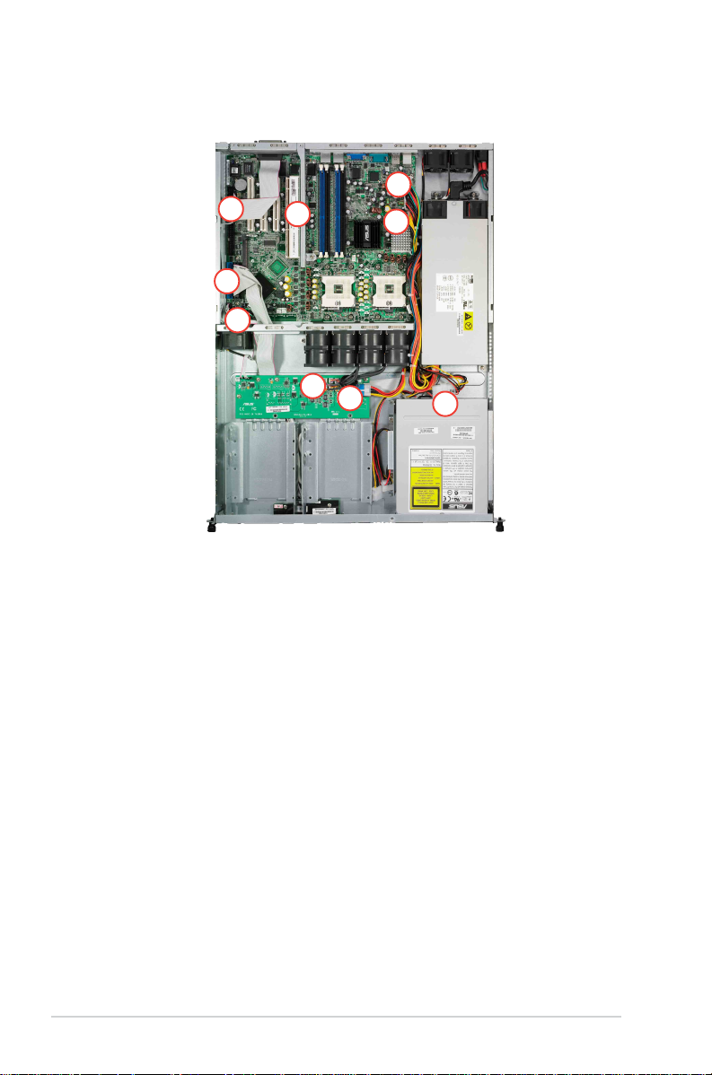
1.5 Internal features
The barebone server includes the basic components as shown.
The AA2 and AI2 models have the same internal features except for the
SATA backplane, fan control board, and HDD trays.
AA2 modelAA2 model
AA2 model
AA2 modelAA2 model
2
1
4
10
5
8 9
3
6
7
1. PCI-X riser card bracket
2. Rear fans
3. ASUS NCCH-DR motherboard
4. Power supply
5. Device fan
6. System fans
AI2 modelAI2 model
AI2 model
AI2 modelAI2 model
7
8 9
AA2AA2
7.
AA2: SATA backplane
AA2AA2
AI2AI2
AI2: Fan control board
AI2AI2
AA2AA2
8.
AA2: Hot-swap HDD tray 1
AA2AA2
AI2AI2
AI2: Internal HDD tray 1
AI2AI2
AA2AA2
9.
AA2: Hot-swap HDD tray 2
AA2AA2
AI2AI2
AI2: Internal HDD tray 2
AI2AI2
10. Optical drive
1-61-6
1-6
1-61-6
The barebone server does not include a floppy disk drive. Connect an
external floppy disk drive (USB interface) to any of the USB ports on the
front or rear panel if you need to use a floppy disk.
Chapter 1: Product introductionChapter 1: Product introduction
Chapter 1: Product introduction
Chapter 1: Product introductionChapter 1: Product introduction
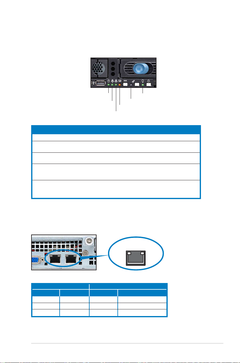
1.6 LED information
1.6.11.6.1
1.6.1
1.6.11.6.1
Front panel LEDsFront panel LEDs
Front panel LEDs
Front panel LEDsFront panel LEDs
HDD Access LEDHDD Access LED
HDD Access LED
HDD Access LEDHDD Access LED
LAN2 LEDLAN2 LED
LAN2 LED
LAN2 LEDLAN2 LED
LAN1 LEDLAN1 LED
LAN1 LED
LAN1 LEDLAN1 LED
LEDLED
LED
LEDLED
Power LED ON System power ON
HDD Access LED OFF No activity
Message LED OFF System is normal; no incoming event
Location LED OFF Normal status
LAN LEDs OFF No LAN connection
Display statusDisplay status
Display status
Display statusDisplay status
Blinking Read/write data into the HDD
Blinking ASWM indicates a HW monitor event
ON Location switch is pressed
Blinking LAN is transmitting or receiving data
ON LAN connection is present
Message LEDMessage LED
Message LED
Message LEDMessage LED
DescriptionDescription
Description
DescriptionDescription
(Press the location switch again to turn off)
Power LEDPower LED
Power LED
Power LEDPower LED
Location LEDLocation LED
Location LED
Location LEDLocation LED
1.6.21.6.2
1.6.2
1.6.21.6.2
Status Description Status Description
OFF No link OFF 10Mbps connection
Green Linked Orange 100Mbps connection
Blinking Linking Green 1000Mbps connection
ASUS AP1600R-E2 (AA2/AI2)ASUS AP1600R-E2 (AA2/AI2)
ASUS AP1600R-E2 (AA2/AI2)
ASUS AP1600R-E2 (AA2/AI2)ASUS AP1600R-E2 (AA2/AI2)
Rear panel LEDsRear panel LEDs
Rear panel LEDs
Rear panel LEDsRear panel LEDs
ACT/LINK LEDACT/LINK LED
ACT/LINK LED
ACT/LINK LEDACT/LINK LED
RJ-45
SPEED LEDSPEED LED
SPEED LED
SPEED LEDSPEED LED
SPEEDACT/LNK
1-71-7
1-7
1-71-7

1-81-8
1-8
1-81-8
Chapter 1: Product introductionChapter 1: Product introduction
Chapter 1: Product introduction
Chapter 1: Product introductionChapter 1: Product introduction

Chapter 2
This chapter lists the hardware
setup procedures that you have to
perform when installing or removing
system components.
ASUS AP1600R-E2 (AA2/AI2)ASUS AP1600R-E2 (AA2/AI2)
ASUS AP1600R-E2 (AA2/AI2)
ASUS AP1600R-E2 (AA2/AI2)ASUS AP1600R-E2 (AA2/AI2)
Hardware setup
2-1

2.1 Chassis cover
2.1.12.1.1
2.1.1
2.1.12.1.1
Removing the coverRemoving the cover
Removing the cover
Removing the coverRemoving the cover
1. Use a Phillips screwdriver to remove the screw on each front end of
the top cover.
ThumbscrewsThumbscrews
Thumbscrews
ThumbscrewsThumbscrews
2. Loosen the two thumbscrews on
the rear panel to release the top
cover from the chassis.
3. Firmly hold the cover and slide it
toward the rear panel for about
half an inch until it is disengaged
from the chassis.
4. Lift the cover from the chassis.
2-22-2
2-2
2-22-2
1/2 inch distance1/2 inch distance
1/2 inch distance
1/2 inch distance1/2 inch distance
Chapter 2: Hardware setupChapter 2: Hardware setup
Chapter 2: Hardware setup
Chapter 2: Hardware setupChapter 2: Hardware setup

2.1.22.1.2
2.1.2
2.1.22.1.2
Installing the coverInstalling the cover
Installing the cover
Installing the coverInstalling the cover
1. Position the cover on top of the chassis with the thumbscrews on the
rear, and leaving a gap of about half an inch from the front panel.
Side markingsSide markings
Side markings
Side markingsSide markings
2. Make sure that the side markings on the cover (two on each side) are
aligned to the grooves on the chassis.
GroovesGrooves
Grooves
GroovesGrooves
3. Slide the cover toward the front until it snaps in place.
4. Tighten the thumbscrews on the rear to secure the cover.
ThumbscrewsThumbscrews
Thumbscrews
ThumbscrewsThumbscrews
ASUS AP1600R-E2 (AA2/AI2)ASUS AP1600R-E2 (AA2/AI2)
ASUS AP1600R-E2 (AA2/AI2)
ASUS AP1600R-E2 (AA2/AI2)ASUS AP1600R-E2 (AA2/AI2)
2-32-3
2-3
2-32-3

2.2 Central Processing Unit (CPU)
The motherboard comes with two surface mount 604-pin Zero Insertion
Force (ZIF) socket and designed for the Intel® Xeon™ processors.
CPU2
CPU1
NCCH-DR
NCCH-DR CPU Socket 604
1. The motherboard supports either one or two CPUs. If you are
installing only one CPU, you MUST install it in CPU socket 1.
2. If you are installing two CPUs, install in the CPU socket 2 first.
2.2.12.2.1
2.2.1
2.2.12.2.1
Installling a CPUInstallling a CPU
Installling a CPU
Installling a CPUInstallling a CPU
To install the CPUs:
1. Locate the CPU sockets on the
motherboard. Flip up the socket
lever and push it all the way to
the other side.
Intel Xeon
Gold Arrow
Pin A1
2-42-4
2-4
2-42-4
Socket for CPU1Socket for CPU1
Socket for CPU1
Socket for CPU1Socket for CPU1
Chapter 2: Hardware setupChapter 2: Hardware setup
Chapter 2: Hardware setup
Chapter 2: Hardware setupChapter 2: Hardware setup

2. Carefully insert the CPU into the
socket as shown until it fits in
place.
The CPU fits only in one
correct orientation. DO NOT
force the CPU into the socket
to prevent bending the pins
and damaging the CPU!
3. Carefully push down the socket
lever to secure the CPU. The
lever clicks on the side tab to
indicate that it is locked.
4. Apply the thermal interface
material (thermal grease) to the
top of the CPU. This thermal
grease should come with the CPU
package.
5. Repeat steps 1 to 4 if you wish
to install a second CPU.
Marked cornerMarked corner
Marked corner
Marked cornerMarked corner
(gold arrow)(gold arrow)
(gold arrow)
(gold arrow)(gold arrow)
ASUS AP1600R-E2 (AA2/AI2)ASUS AP1600R-E2 (AA2/AI2)
ASUS AP1600R-E2 (AA2/AI2)
ASUS AP1600R-E2 (AA2/AI2)ASUS AP1600R-E2 (AA2/AI2)
2-52-5
2-5
2-52-5
2.2.22.2.2
2.2.2
2.2.22.2.2
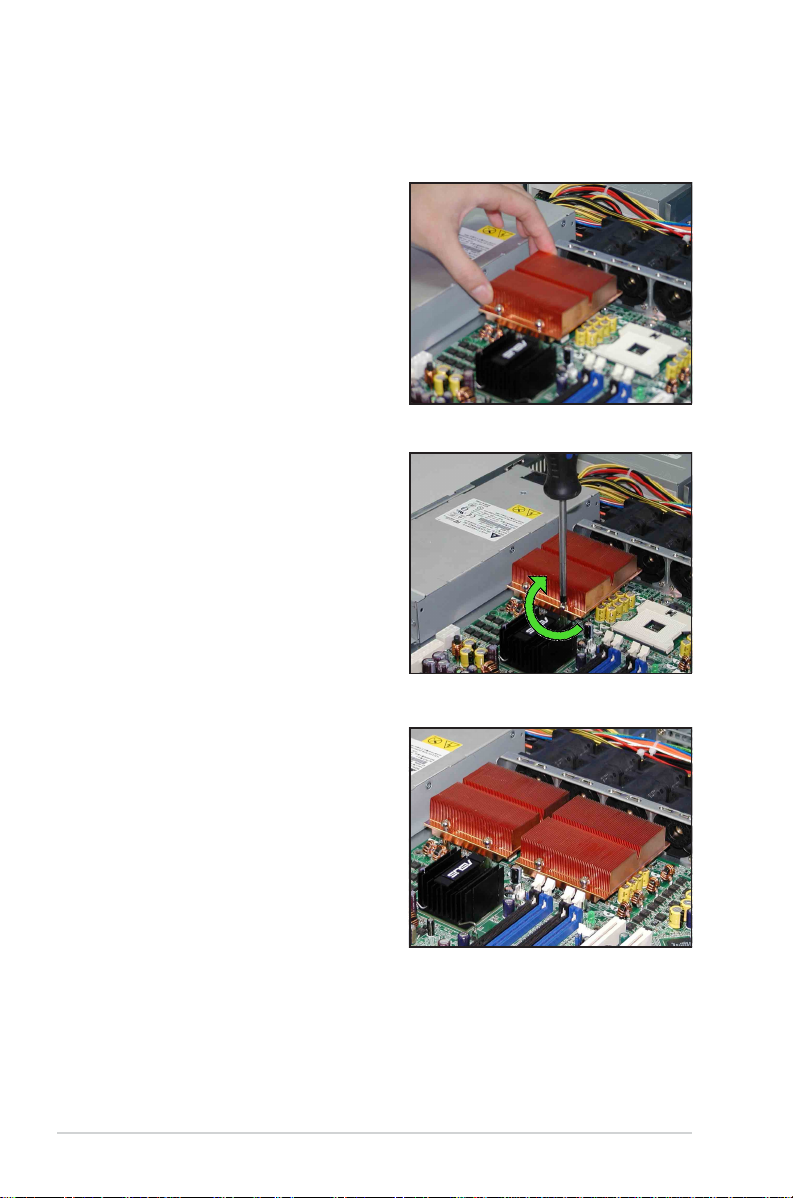
To install the CPU heatsink:
1. Carefully place the heatsink on
2. Twist each of the four screws
Installing the CPU heatsinkInstalling the CPU heatsink
Installing the CPU heatsink
Installing the CPU heatsinkInstalling the CPU heatsink
top of the installed CPU.
with a Philips (cross) screwdriver
just enough to attach the
heatsink to the motherboard.
When the four screws are
attached, tighten them one by
one to completely secure the
heatsink.
3. Follow steps 1 and 2 to install
the second CPU heatsink.
2-62-6
2-6
2-62-6
Chapter 2: Hardware setupChapter 2: Hardware setup
Chapter 2: Hardware setup
Chapter 2: Hardware setupChapter 2: Hardware setup

2.4 System memory
2.4.12.4.1
2.4.1
2.4.12.4.1
OverviewOverview
Overview
OverviewOverview
The motherboard comes with four Double Data Rate (DDR) Dual Inline
Memory Modules (DIMM) sockets.
80 Pins104 Pins
DIMM_A1
DIMM_A2
DIMM_B1
2.4.22.4.2
2.4.2
2.4.22.4.2
NCCH-DR
NCCH-DR 184-Pin DDR DIMM sockets
Memory configurationsMemory configurations
Memory configurations
Memory configurationsMemory configurations
DIMM_B2
You may install 128 MB, 256 MB, 512 MB, 1 GB, and 2 GB unbuffered ECC
or non-ECC DDR DIMMs into the DIMM sockets.
• Always install DIMMs with the same CAS latency. For optimum
compatibility, it is recommended that you obtain memory modules
from the same vendor. Refer to the DDR Qualified Vendors List on
the ASUS website for details.
• Due to chipset resource allocation, the system may detect less than
8 GB system memory when you install four 2 GB DDR memory
modules.
• This motherboard does not support memory modules made up of
128 Mb chips or double sided x16 memory modules.
• Three DDR DIMMs intalled into any three memory sockets will
function in single-channel mode.
ASUS AP1600R-E2 (AA2/AI2)ASUS AP1600R-E2 (AA2/AI2)
ASUS AP1600R-E2 (AA2/AI2)
ASUS AP1600R-E2 (AA2/AI2)ASUS AP1600R-E2 (AA2/AI2)
2-72-7
2-7
2-72-7

2.4.32.4.3
2.4.3
2.4.32.4.3
Installing a DIMMInstalling a DIMM
Installing a DIMM
Installing a DIMMInstalling a DIMM
Make sure to unplug the power supply before adding or removing DIMMs
or other system components. Failure to do so may cause severe damage
to both the motherboard and the components.
1. Unlock a DIMM socket by
pressing the retaining clips
outward.
2. Align a DIMM on the socket such
that the notch on the DIMM
matches the break on the
socket.
A DDR DIMM is keyed with a notch so that it fits in only one direction.
DO NOT force a DIMM into a socket to avoid damaging the DIMM.
3. Firmly insert the DIMM into the
socket until the retaining clips
snap back in place and the DIMM
is properly seated.
2
DDR DIMM notchDDR DIMM notch
DDR DIMM notch
DDR DIMM notchDDR DIMM notch
1
1
Unlocked retaining clipUnlocked retaining clip
Unlocked retaining clip
Unlocked retaining clipUnlocked retaining clip
2.4.42.4.4
2.4.4
2.4.42.4.4
Removing a DIMMRemoving a DIMM
Removing a DIMM
Removing a DIMMRemoving a DIMM
Follow these steps to remove a DIMM.
1. Simultaneously press the
retaining clips outward to unlock
the DIMM.
Support the DIMM lightly with your fingers when pressing the retaining
clips. The DIMM might get damaged when it flips out with extra force.
2. Remove the DIMM from the socket.
2-82-8
2-8
2-82-8
Locked Retaining ClipLocked Retaining Clip
Locked Retaining Clip
Locked Retaining ClipLocked Retaining Clip
2
1
DDR DIMM notchDDR DIMM notch
DDR DIMM notch
DDR DIMM notchDDR DIMM notch
Chapter 2: Hardware setupChapter 2: Hardware setup
Chapter 2: Hardware setup
Chapter 2: Hardware setupChapter 2: Hardware setup
1

2.4 Hard disk drives
2.4.12.4.1
2.4.1
2.4.12.4.1
To install a hot-swap SATA HDD:
1. Release a drive tray by pushing
2. Firmly hold the tray lever and
3. Take note of the drive tray
Installing a hot-swap SATA HDD Installing a hot-swap SATA HDD
Installing a hot-swap SATA HDD
Installing a hot-swap SATA HDD Installing a hot-swap SATA HDD
the spring lock to the right, then
pulling the tray lever outward.
The drive tray ejects slightly
after you pull out the lever.
pull the drive tray out of the
bay.
holes. Each side has three holes
to fit different types of hard disk
drives. Use two screws on each
side to secure the hard disk
drive.
(AA2 model)(AA2 model)
(AA2 model)
(AA2 model)(AA2 model)
4. Place a SATA hard disk drive on
the tray, then secure it with four
screws.
ASUS AP1600R-E2 (AA2/AI2)ASUS AP1600R-E2 (AA2/AI2)
ASUS AP1600R-E2 (AA2/AI2)
ASUS AP1600R-E2 (AA2/AI2)ASUS AP1600R-E2 (AA2/AI2)
2-92-9
2-9
2-92-9
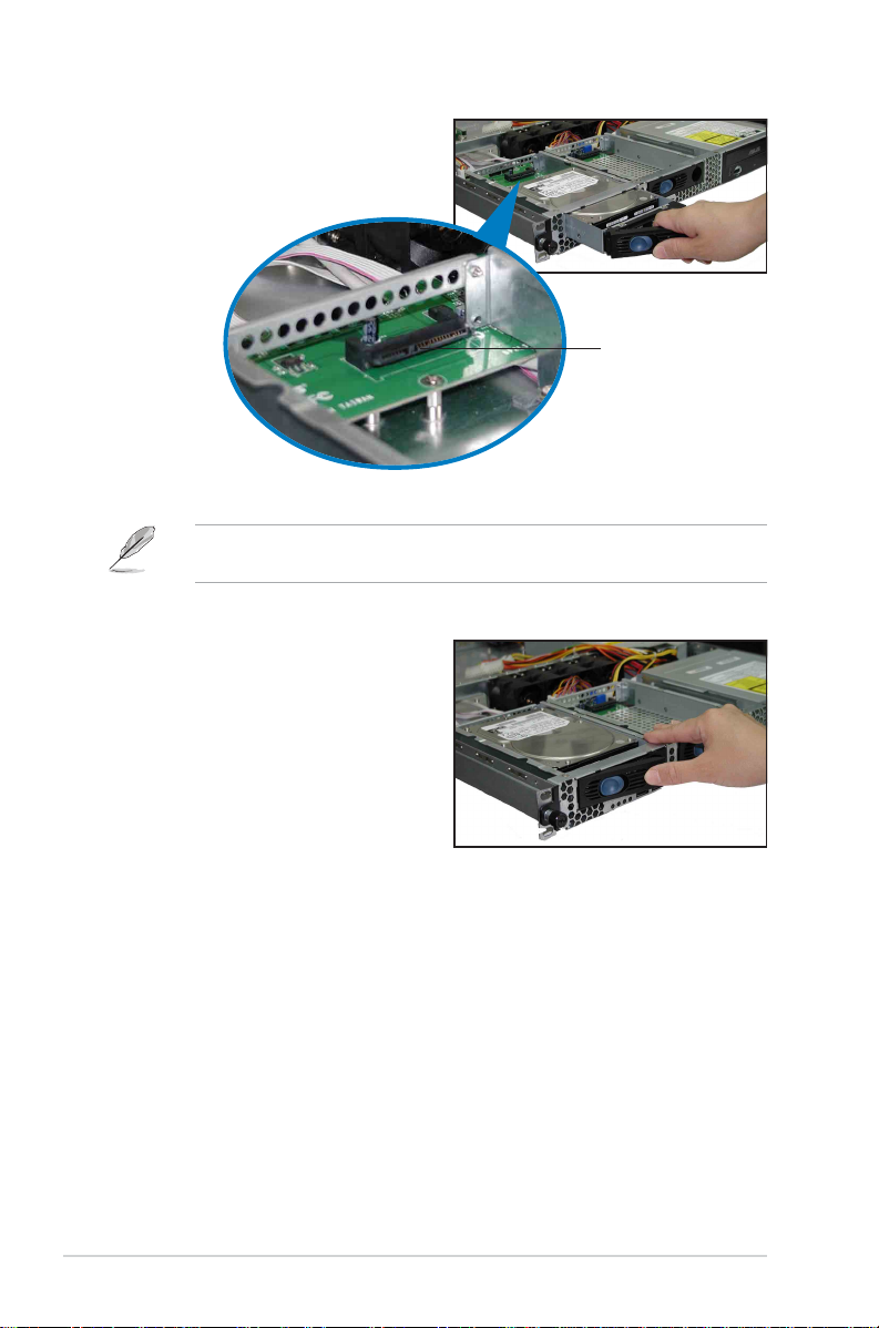
5. Carefully insert the drive tray
and push it all the way to the
depth of the bay until just a
small fraction of the tray edge
protrudes.
When installed, the SATA connector on the drive connects to the SATA
interface on the backplane.
6. Push the tray lever until it clicks,
and secures the drive tray in
place. The drive tray is correctly
placed when its front edge aligns
with the bay edge.
7. Repeat steps 1 to 6 if you wish
to install a second SATA drive.
SATA interfaceSATA interface
SATA interface
SATA interfaceSATA interface
on the backplaneon the backplane
on the backplane
on the backplaneon the backplane
8. Connect the bundled SATA cables to the connectors on the SATA
backplane. Refer to section “2.7 SATA backplane cabling” for
information on the SATA backplane cable connections.
2-102-10
2-10
2-102-10
Chapter 2: Hardware setupChapter 2: Hardware setup
Chapter 2: Hardware setup
Chapter 2: Hardware setupChapter 2: Hardware setup

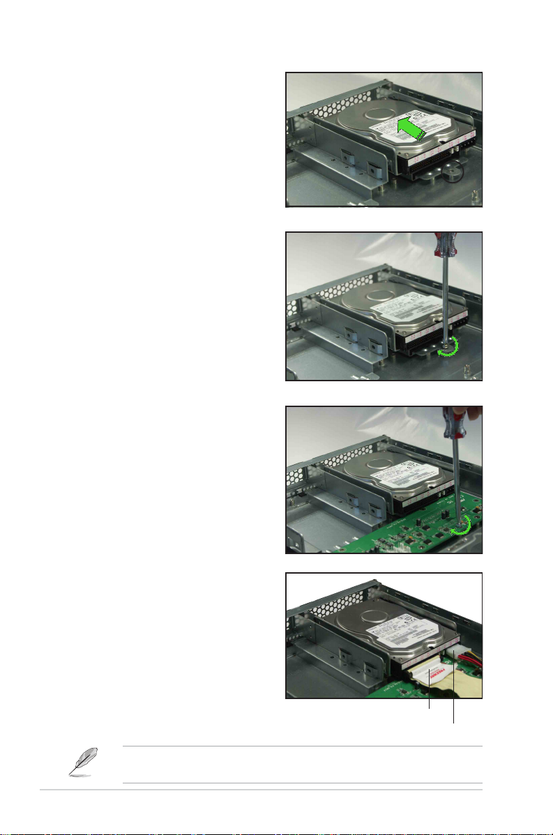
2.4.22.4.2
2.4.2
2.4.22.4.2
To install an IDE HDD:
1. Disconnect all the cables from
2. Remove the screw that secures
Installing an IDE HDD Installing an IDE HDD
Installing an IDE HDD
Installing an IDE HDD Installing an IDE HDD
the fan control board. Use a
Phillips (cross) screwdriver to
remove the five screws that
secure the fan control board.
Fan control board screwsFan control board screws
Fan control board screws
Fan control board screwsFan control board screws
the hard disk tray to the chassis.
Slide the tray backward until the
two tray lock tabs are
disengaged. Lift the tray from
the bay.
(AI2 model)(AI2 model)
(AI2 model)
(AI2 model)(AI2 model)
Lock tab
3. Place a hard disk drive on the
drive tray, and secure it with
four screws.
ASUS AP1600R-E2 (AA2/AI2)ASUS AP1600R-E2 (AA2/AI2)
ASUS AP1600R-E2 (AA2/AI2)
ASUS AP1600R-E2 (AA2/AI2)ASUS AP1600R-E2 (AA2/AI2)
2-112-11
2-11
2-112-11
4. Carefully place the tray with
installed hard disk drive into the
drive bay. Slide it forward until
the front end aligns with the
front panel, and the screw hole
matches the standoff.
5. Secure the tray with a screw.
6. Repeat steps 2 to 5 if you wish
to install a second HDD;
otherwise, proceed to step 7.
7. Reinstall the fan control board.
Secure the board with five
screws.
8. Connect the 40-pin IDE cable
and a 4-pin power plug to their
respective connectors on the
back of the drive.
The other end of the IDE cable is pre-connected to the primary IDE
connector on the motherboard.
2-122-12
2-12
2-122-12
40-pin IDE cable40-pin IDE cable
40-pin IDE cable
40-pin IDE cable40-pin IDE cable
4-pin power plug4-pin power plug
4-pin power plug
4-pin power plug4-pin power plug
Chapter 2: Hardware setupChapter 2: Hardware setup
Chapter 2: Hardware setup
Chapter 2: Hardware setupChapter 2: Hardware setup

2.4.32.4.3
2.4.3
2.4.32.4.3
To install an internal SATA HDD:
1. Follow steps 1 to 7 in section
2. Connect the 7-pin SATA cable
Installing an internal SATA HDD Installing an internal SATA HDD
Installing an internal SATA HDD
Installing an internal SATA HDD Installing an internal SATA HDD
“2.4.2 Installing an IDE hard
disk drive.”
to the SATA connector on the
back of the drive. Connect the
other end to an SATA
connector on the motherboard.
(AI2 model)(AI2 model)
(AI2 model)
(AI2 model)(AI2 model)
SATA connector
7-pin SATA cable
3. Connect the HDD power cable.
• If you are using SATA HDDs
4-pin (female) device plug from the power supply to the 4-pin (male)
power connector on the back of the drive as shown above.
• If you are using SATA HDDs
purchase a SATA power cable with a 4-pin/15pin plugs. Connect a
4-pin (female) device plug from the power supply to the 4-pin (male)
plug of the SATA power cable. Connect the 15-pin SATA power plug
to the power connector on the back of the drive.
4. Repeat steps 1 to 3 to install a second SATA drive.
Ensure that all cables are held together with the cable clamp, specially
those near the system fans. Loose cables may get caught with the fan
blades causing fan failure! See step 7 of section “2.4.2 Installing an
IDE HDD.”!
with a 4-pin power connector
without a 4-pin power connector
4-pin device power cable
, connect a
,
ASUS AP1600R-E2 (AA2/AI2)ASUS AP1600R-E2 (AA2/AI2)
ASUS AP1600R-E2 (AA2/AI2)
ASUS AP1600R-E2 (AA2/AI2)ASUS AP1600R-E2 (AA2/AI2)
2-132-13
2-13
2-132-13

2.5 Expansion slot
2.5.12.5.1
2.5.1
2.5.12.5.1
Installing an expansion cardInstalling an expansion card
Installing an expansion card
Installing an expansion cardInstalling an expansion card
The barebone server comes with a riser card bracket. You need to remove
the bracket if you wish to install a PCI-X expansion card.
To install a PCI-X card:
1. Use a Phillips (cross) screwdriver to remove the screw that secures
the riser card to the standoff.
Riser card screwRiser card screw
Riser card screw
Riser card screwRiser card screw
Riser card standoffRiser card standoff
Riser card standoff
Riser card standoffRiser card standoff
2. Firmly hold a riser card bracket,
then pull it up to detach it from
the PCI-X slot on the
motherboard.
3. Remove the screw that secures
the slot metal cover.
4. Install a PCI-X card to the
bracket as shown, then secure
the card with a screw.
2-142-14
2-14
2-142-14
Chapter 2: Hardware setupChapter 2: Hardware setup
Chapter 2: Hardware setup
Chapter 2: Hardware setupChapter 2: Hardware setup
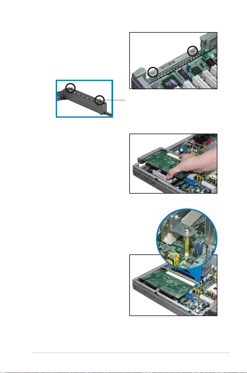
5. Take note of the holes on the
riser card bay. The two pegs on
the riser card bracket should
match these holes to ensure
that the bracket is properly in
place.
Peg on the riserPeg on the riser
Peg on the riser
Peg on the riserPeg on the riser
card bracketcard bracket
card bracket
card bracketcard bracket
6. Install the riser card bracket with
the card into the PCI-X slot on
the motherboard.
7. Make sure that the golden
connectors completely fit the
slot and the bracket aligns with
the rear panel.
8. Secure the riser card to the
standoff.
9. Connect the cable(s) to the
card, if applicable.
ASUS AP1600R-E2 (AA2/AI2)ASUS AP1600R-E2 (AA2/AI2)
ASUS AP1600R-E2 (AA2/AI2)
ASUS AP1600R-E2 (AA2/AI2)ASUS AP1600R-E2 (AA2/AI2)
2-152-15
2-15
2-152-15
2.5.22.5.2
2.5.2
2.5.22.5.2
Configuring an expansion cardConfiguring an expansion card
Configuring an expansion card
Configuring an expansion cardConfiguring an expansion card
After installing the expansion card, configure the it by adjusting the
software settings.
1. Turn on the system and change the necessary BIOS settings, if any.
See Chapter 5 for information on BIOS setup.
2. Assign an IRQ to the card. Refer to the following tables.
3. Install the software drivers for the expansion card.
Standard interrupt assignmentsStandard interrupt assignments
Standard interrupt assignments
Standard interrupt assignmentsStandard interrupt assignments
IRQ Priority Standard Function
0 1 System Timer
1 2 Keyboard Controller
2 N/A Programmable Interrupt
3* 11 Communications Port (COM2)
4* 12 Communications Port (COM1)
5* 13 Sound Card (sometimes LPT2)
6 14 Floppy Disk Controller
7* 15 Printer Port (LPT1)
8 3 System CMOS/Real Time Clock
9* 4 ACPI Mode when used
10* 5 IRQ Holder for PCI Steering
11* 6 IRQ Holder for PCI Steering
12* 7 PS/2 Compatible Mouse Port
13 8 Numeric Data Processor
14* 9 Primary IDE Channel
15* 10 Secondary IDE Channel
* These IRQs are usually available for ISA or PCI devices.
IRQ assignments for this motherboardIRQ assignments for this motherboard
IRQ assignments for this motherboard
IRQ assignments for this motherboardIRQ assignments for this motherboard
INTA# INTB# INTC# INTD# REQ# GNT#
ATI Rage XL PIRQB# — — — REQ2# GNT2#
BCM5705E PIRQF# — — — REQ3# GNT3#
PCIX slot 1 (64-bit) PXIRQ0 PXIRQ1 PXIRQ2 PXIRQ3 X_REQ0 X_GNT0
When using PCI cards on shared slots, ensure that the drivers support
“Share IRQ” or that the cards do not need IRQ assignments. Otherwise,
conflicts will arise between the two PCI groups, making the system
unstable and the card inoperable.
2-162-16
2-16
2-162-16
Chapter 2: Hardware setupChapter 2: Hardware setup
Chapter 2: Hardware setup
Chapter 2: Hardware setupChapter 2: Hardware setup
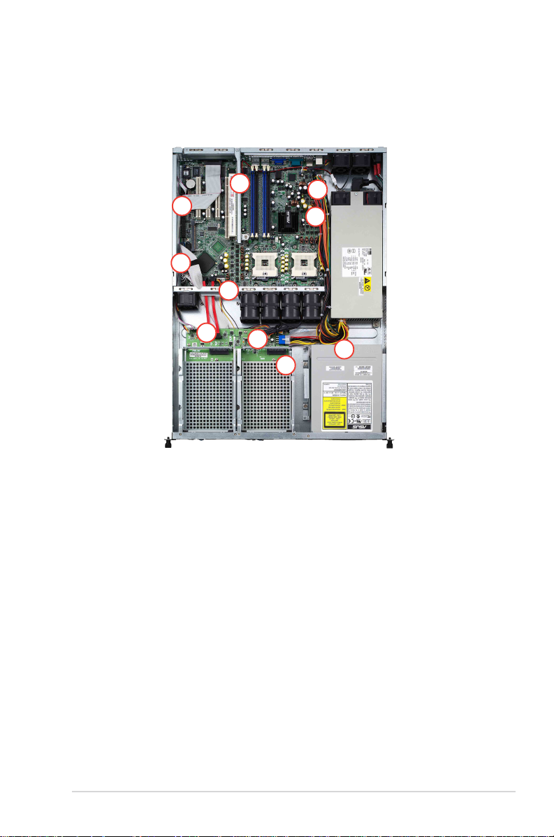
2.6 Cable connections
AA2 modelAA2 model
AA2 model
AA2 modelAA2 model
2
1
3
4
5
6
7
8
10
9
Pre-connected system cablesPre-connected system cables
Pre-connected system cables
Pre-connected system cablesPre-connected system cables
1. Parallel port cable (from motherboard to rear panel)
2. Rear fan connector (from power supply to motherboard)
3. 24-pin SSI power connector (from power supply to motherboard)
4. 8-pin SSI power connector (power supply to motherboard)
5. Secondary IDE connector (from motherboard to optical drive)
6. Device fan connector (from motherboard to SATA backplane board)
7. SATA connectors (from motherboard to SATA backplane board)
8. System fan connectors (from mid-fans to SATA backplane)
9. SATA backplane power connector (from power supply)
10. 4-pin power connector (from power supply to optical drive)
ASUS AP1600R-E2 (AA2/AI2)ASUS AP1600R-E2 (AA2/AI2)
ASUS AP1600R-E2 (AA2/AI2)
ASUS AP1600R-E2 (AA2/AI2)ASUS AP1600R-E2 (AA2/AI2)
2-172-17
2-17
2-172-17
AI2 modelAI2 model
AI2 model
AI2 modelAI2 model
3
1
2
4
5
6
7
8
Pre-connected system cablesPre-connected system cables
Pre-connected system cables
Pre-connected system cablesPre-connected system cables
1. Parallel port cable (from motherboard to rear panel)
2. Rear fan connector (from power supply to motherboard)
3. 24-pin SSI power connector (from power supply to motherboard)
4. 8-pin SSI power connector (power supply to motherboard)
5. Secondary IDE connector (from motherboard to optical drive)
6. Device fan connector (from device fan to motherboard)
7. System fan connectors (from mid-fans to SATA backplane)
8. Fan control board power connector (from power supply)
9. 4-pin power connector (from power supply to optical drive)
9
2-182-18
2-18
2-182-18
Chapter 2: Hardware setupChapter 2: Hardware setup
Chapter 2: Hardware setup
Chapter 2: Hardware setupChapter 2: Hardware setup
2.7 Removable components
You may need to remove previously installed system components when
installing or removing system devices, or when you need to replace
defective components. This section tells how to remove the following
components:
1. System fans
2. Device fan
3. Power supply module
4. Optical drive
5. Motherboard
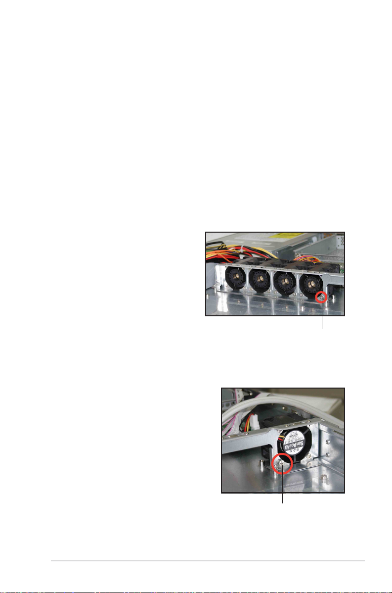
2.7.12.7.1
2.7.1
2.7.12.7.1
To uninstall the system fans:
1. Disconnect all the system fan
2. Remove the four screws that
3. Repeat step 2 to uninstall the
2.7.22.7.2
2.7.2
2.7.22.7.2
To uninstall the device fan:
1. Disconnect the system fan cable
2. Remove the four screws that secure
System fansSystem fans
System fans
System fansSystem fans
cables from the connectors on
the backplane board.
secure a fan.
other fans.
Device fanDevice fan
Device fan
Device fanDevice fan
from the connector on the
motherboard.
the device fan.
Fan screwFan screw
Fan screw
Fan screwFan screw
ASUS AP1600R-E2 (AA2/AI2)ASUS AP1600R-E2 (AA2/AI2)
ASUS AP1600R-E2 (AA2/AI2)
ASUS AP1600R-E2 (AA2/AI2)ASUS AP1600R-E2 (AA2/AI2)
Fan screwFan screw
Fan screw
Fan screwFan screw
2-192-19
2-19
2-192-19

2.7.32.7.3
2.7.3
2.7.32.7.3
To uninstall the power supply module:
1. Disconnect all the power cables
2. Use a Phillips (cross) screwdriver
Power supply modulePower supply module
Power supply module
Power supply modulePower supply module
connected to the motherboard and
other system devices.
to remove the screw the secures
the front end of the power
supply.
3. Slide the power supply backward for about half an inch, then carefully
lift it out from the chassis.
2-202-20
2-20
2-202-20
Chapter 2: Hardware setupChapter 2: Hardware setup
Chapter 2: Hardware setup
Chapter 2: Hardware setupChapter 2: Hardware setup

2.7.42.7.4
2.7.4
2.7.42.7.4
Optical driveOptical drive
Optical drive
Optical driveOptical drive
To uninstall the optical drive:
1. Please use a pin-ejector (paper
clipper may be used) for trayout.. (or you can open the tray
by pushing the “open botton”)
When changing ODD, the black ODD front plastic housing is already
removed. User can uninstall/install ODD after remove the tray bezel.
2. Then remove the tray bezel
demonstrated in the photo.
3. Disconnect the power and signal
cabled connected to the rear of
the ODD.
4. Use a Philips (cross) screwdriver
to remove the two screws that
secure the metal bracket on the
side of the ODD.
5. Remove the bracket to release
the drive.
ASUS AP1600R-E2 (AA2/AI2)ASUS AP1600R-E2 (AA2/AI2)
ASUS AP1600R-E2 (AA2/AI2)
ASUS AP1600R-E2 (AA2/AI2)ASUS AP1600R-E2 (AA2/AI2)
2-212-21
2-21
2-212-21

To install an optical drive:
1. Please follow previous Step 1
instructions to tray-out and to
remove the ODD bezel.
2. Then put the ODD inside the server and insert ODD into the ODD bay.
The purpose of the metal bracket is to secure the ODD us securely in
place.
Drive holes to match the
pegs on the metal bracket
Drive metal bracket
Bracket pegs
Standoffs to match the
holes on the metal bracket
3. Secure the bracket with two
screws and re-connect the power
and signal cables in place. Put back
the tray bezel to finish ODD
installation.
2-222-22
2-22
2-222-22
Holes to match the standoffs
Chapter 2: Hardware setupChapter 2: Hardware setup
Chapter 2: Hardware setup
Chapter 2: Hardware setupChapter 2: Hardware setup

2.7.52.7.5
2.7.5
2.7.52.7.5
To uninstall the motherboard:
1. Disconnect all the pre-connected cables from the motherboard. See
2. Uninstall all the devices from the motherboard including the CPU and
3. Remove the riser card standoff by twisting it counterclockwise.
3. Use a Phillips (cross) screwdriver
MotherboardMotherboard
Motherboard
MotherboardMotherboard
section “2.6 Cable connections” for illustration.
heatsink, riser card bracket, and DDR DIMMs. Refer to the
corresponding sections for instructions on removing these
components.
Riser card standoffRiser card standoff
Riser card standoff
Riser card standoffRiser card standoff
to remove the screws that
secure the motherboard to the
base of the chassis.
4. Carefully lift the motherboard
out of the chassis as shown.
ASUS AP1600R-E2 (AA2/AI2)ASUS AP1600R-E2 (AA2/AI2)
ASUS AP1600R-E2 (AA2/AI2)
ASUS AP1600R-E2 (AA2/AI2)ASUS AP1600R-E2 (AA2/AI2)
2-232-23
2-23
2-232-23

To reinstall the motherboard:
1. Firmly hold the motherboard by
the sides and insert it into the
chassis as shown.
2. Carefully adjust the motherboard
until the rear panel ports fit in
place.
3. Use a Phillips (cross) screwdriver
to secure the motherboard with
nine (9) screws in the holes as
shown.
2-242-24
2-24
2-242-24
NCCH-DR
Screw holeScrew hole
Screw hole
Screw holeScrew hole
Chapter 2: Hardware setupChapter 2: Hardware setup
Chapter 2: Hardware setup
Chapter 2: Hardware setupChapter 2: Hardware setup

4. Insert the riser card standoff
into the motherboard hole
beside the PCI-X slot, and twist it
clockwise until secure.
5. Reconnect all the required cables to the motherboard. See section
“2.6 Cable connections” for illustration.
6. Reinstall all the devices that you have previously removed.
ASUS AP1600R-E2 (AA2/AI2)ASUS AP1600R-E2 (AA2/AI2)
ASUS AP1600R-E2 (AA2/AI2)
ASUS AP1600R-E2 (AA2/AI2)ASUS AP1600R-E2 (AA2/AI2)
2-252-25
2-25
2-252-25

2.8 SATA backplane cabling
(for AA2)
Connects the SMBusConnects the SMBus
Connects the SMBus
Connects the SMBusConnects the SMBus
cable from the MBcable from the MB
cable from the MB
cable from the MBcable from the MB
Connect the SATAConnect the SATA
Connect the SATA
Connect the SATAConnect the SATA
cables from the MBcables from the MB
cables from the MB
cables from the MBcables from the MB
Connects theConnects the
Connects the
Connects theConnects the
device fan cabledevice fan cable
device fan cable
device fan cabledevice fan cable
(FAN1) Connects the fan cable(FAN1) Connects the fan cable
(FAN1) Connects the fan cable
(FAN1) Connects the fan cable(FAN1) Connects the fan cable
from CPU_FAN1 on the MBfrom CPU_FAN1 on the MB
from CPU_FAN1 on the MB
from CPU_FAN1 on the MBfrom CPU_FAN1 on the MB
Connect theConnect the
Connect the
Connect theConnect the
system fan cablessystem fan cables
system fan cables
system fan cablessystem fan cables
Connect the SATA HDDsConnect the SATA HDDs
Connect the SATA HDDs
Connect the SATA HDDsConnect the SATA HDDs
Connects a 4-pin plugConnects a 4-pin plug
Connects a 4-pin plug
Connects a 4-pin plugConnects a 4-pin plug
from power supplyfrom power supply
from power supply
from power supplyfrom power supply
2-262-26
2-26
2-262-26
Chapter 2: Hardware setupChapter 2: Hardware setup
Chapter 2: Hardware setup
Chapter 2: Hardware setupChapter 2: Hardware setup

2.9 Fan control board cabling
(for AI2)
Connects the SMBusConnects the SMBus
Connects the SMBus
Connects the SMBusConnects the SMBus
cable from the MBcable from the MB
cable from the MB
cable from the MBcable from the MB
Connects theConnects the
Connects the
Connects theConnects the
device fan cabledevice fan cable
device fan cable
device fan cabledevice fan cable
(FAN1) Connects the fan cable(FAN1) Connects the fan cable
(FAN1) Connects the fan cable
(FAN1) Connects the fan cable(FAN1) Connects the fan cable
from CPU_FAN1 on the MBfrom CPU_FAN1 on the MB
from CPU_FAN1 on the MB
from CPU_FAN1 on the MBfrom CPU_FAN1 on the MB
Connect theConnect the
Connect the
Connect theConnect the
system fan cablessystem fan cables
system fan cables
system fan cablessystem fan cables
Connects a 4-pin plugConnects a 4-pin plug
Connects a 4-pin plug
Connects a 4-pin plugConnects a 4-pin plug
from power supplyfrom power supply
from power supply
from power supplyfrom power supply
ASUS AP1600R-E2 (AA2/AI2)ASUS AP1600R-E2 (AA2/AI2)
ASUS AP1600R-E2 (AA2/AI2)
ASUS AP1600R-E2 (AA2/AI2)ASUS AP1600R-E2 (AA2/AI2)
2-272-27
2-27
2-272-27

2-282-28
2-28
2-282-28
Chapter 2: Hardware setupChapter 2: Hardware setup
Chapter 2: Hardware setup
Chapter 2: Hardware setupChapter 2: Hardware setup

Chapter 3
This chapter describes how to
install the optional components and
devices into the barebone server.
ASUS AP1600R-E2 (AA2/AI2)ASUS AP1600R-E2 (AA2/AI2)
ASUS AP1600R-E2 (AA2/AI2)
ASUS AP1600R-E2 (AA2/AI2)ASUS AP1600R-E2 (AA2/AI2)
Installation options
2-1

3.1 Rackmount rail kit items
If you have the rackmount rail kit, it contains two pairs of rails (one pair for
each side of the barebone system), and eight (8) pairs of nut-and-bolt
type screws.
NutsNuts
Nuts
NutsNuts
BoltsBolts
Bolts
BoltsBolts
Left pairLeft pair
Left pair
Left pairLeft pair
Right pairRight pair
Right pair
Right pairRight pair
3.2 Rack rails assembly
To assemble the rack rails:
1. Determine the depth of the rack where you wish to install the system.
2. Match one long and one short rail to your desired length, and fix them
together using four (4) pairs of nuts and bolts.
3. Repeat step 2 to assemble the other rail pair.
Rear endsRear ends
Rear ends
Rear endsRear ends
Bolts on inner sideBolts on inner side
Bolts on inner side
Bolts on inner sideBolts on inner side
Nuts on outer sideNuts on outer side
Nuts on outer side
Nuts on outer sideNuts on outer side
Front endsFront ends
Front ends
Front endsFront ends
3-23-2
3-2
3-23-2
Chapter 3: Installation optionsChapter 3: Installation options
Chapter 3: Installation options
Chapter 3: Installation optionsChapter 3: Installation options
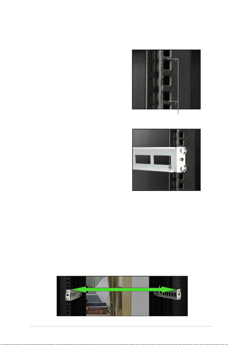
3.3 Attaching the rails to the rack
To attach the rails to the rack:
1. Select one unit of space (1U) on the
rack where you wish to install the
barebone server.
2. Remove the screws from the 1U space
on the rack front.
1U space
3. Align the front end holes of a rack rail
pair to the 1U space.
4. Drive in two screws on the outer holes
to secure the front end.
5. Find the
rear 1U spacerear 1U space
rear 1U space that corresponds to the
rear 1U spacerear 1U space
front 1U spacefront 1U space
front 1U space
front 1U spacefront 1U space
where you attached the rail.
6. Remove the screws from the rear 1U space, and align the rear end
holes.
7. Drive in two screws on the outer holes to secure the rear end.
8. From the rack front, find the corresponding 1U space for the second
rail pair.
9. Repeat steps 2 to 7 to attach the second rail pair. When properly
installed, the rack rails appear as shown.
ASUS AP1600R-E2 (AA2/AI2)ASUS AP1600R-E2 (AA2/AI2)
ASUS AP1600R-E2 (AA2/AI2)
ASUS AP1600R-E2 (AA2/AI2)ASUS AP1600R-E2 (AA2/AI2)
3-33-3
3-3
3-33-3

3.4 Rackmounting the server
To mount the server to the rack:
1. Firmly hold the server on both sides and insert the rear panel side to
the front end of the rack rail, then carefully push the server all the
way to the back until the front panel fits the front end of the rack,
and the rack screws on the server match the middle hole on the rack..
2. Tighten the two rack screws to secure
the server to the rack.
3-43-4
3-4
3-43-4
Rack screwRack screw
Rack screw
Rack screwRack screw
Chapter 3: Installation optionsChapter 3: Installation options
Chapter 3: Installation options
Chapter 3: Installation optionsChapter 3: Installation options

Chapter 4
This chapter includes the
motherboard layout, and brief
descriptions of the jumpers and
internal connectors.
ASUS AP1600R-E2 (AA2/AI2)ASUS AP1600R-E2 (AA2/AI2)
ASUS AP1600R-E2 (AA2/AI2)
ASUS AP1600R-E2 (AA2/AI2)ASUS AP1600R-E2 (AA2/AI2)
Motherboard info
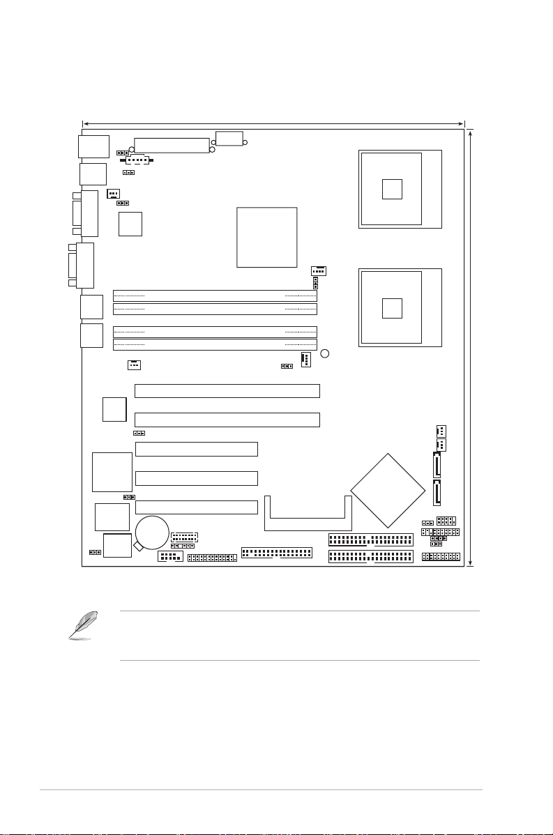
4.1 Motherboard layout
26.8cm (10.5in)
PS/2KBMS
T: Mouse
B: Keyboard
USB12
COM1
KBPWR1
PSUSMB1
USBPW12
REAR_FAN2
Intel
82547GI
Gigabit
Ethernet
ATXPWR1
LAN_EN1
ATX12V1
Intel
MCH
E7210
CPU2
mPGA 604
VGA
LAN1
LAN2
RAGE XL
Controller
CLRTC1
Intel
82541GI
Gigabit
Ethernet
LAN_EN2
ATI
VGA
VGA_EN1
Super
I/O
8Mbit
DDR DIMM_A1 (64 bit,184-pin module)
DDR DIMM_A2 (64 bit,184-pin module)
DDR DIMM_B1 (64 bit,184-pin module)
DDR DIMM_B2 (64 bit,184-pin module)
REAR_FAN1
PCIX1
(64-bit, 66MHz 3V)
PCIX2
(64-bit, 66MHz 3V)
PCI3 (32-bit, 33MHz 5V)
PCI4 (32-bit, 33MHz 5V)
PCI5 (32-bit, 33MHz 5V)
CR2032 3V
Flash
BIOS
Lithium Cell
CMOS Power
COM2
BMCCONN1
BPSMB1
FM_CPU1
FLOPPY
LPT1
NCCH-DR
FM_CPU2
CPU_FAN1
BMCSOCKET1
SEC_IDE
PRI_IDE
CPU_FAN2
SB_PWR1
CPU1
Intel
ICH
6300ESB
AUX_PANEL1
FRNT_FAN2
FRNT_FAN1
SATA2
SATA1
USBPW34
HDLED
The four grayed out card slots are present on the motherboard but are
not used in this system. You may install one PCI-X card via the riser card
bracket.
mPGA 604
30.5cm (12in)
USB34
RECOVERY
PANEL1
4-24-2
4-2
4-24-2
Chapter 4: Motherboard informationChapter 4: Motherboard information
Chapter 4: Motherboard information
Chapter 4: Motherboard informationChapter 4: Motherboard information
Layout contentsLayout contents
Layout contents
Layout contentsLayout contents
SlotsSlots
Slots
SlotsSlots
PagePage
Page
PagePage
1. CPU sockets 2-13
2. DDR DIMM sockets 2-16
3. PCI/PCI-X slots 2-20
JumpersJumpers
Jumpers
JumpersJumpers
PagePage
Page
PagePage
Clear RTC RAM (CLRTC1) 2-21
CPU fan pin selection (3-pin FM_CPU1, FM_CPU2) 2-22
USB device wake-up (3-pin USBPW12, USBPW34) 2-22
Keyboard power (3-pin KBPWR1) 2-23
SATA controller setting (3-pin SATA_EN1)
SATA controller LED setting (3-pin 8130LED1)
SATA models only
SATA models only
2-23
2-24
Gigabit LAN controller setting (3-pin LAN_EN1; LAN_EN2) 2-24
Integrated graphics controller (3-pin VGA_EN1) 2-25
Force BIOS recovery (3-pin RECOVERY) 2-25
Rear panel connectorsRear panel connectors
Rear panel connectors
Rear panel connectorsRear panel connectors
PagePage
Page
PagePage
1. PS/2 mouse port (green) 2-26
2. PS/2 keyboard port (purple) 2-26
3. USB 2.0 ports 1 and 2 2-26
4. Serial (COM1) port 2-26
5. VGA port 2-26
6. LAN1 (RJ-45) port 2-26
7. LAN2 (RJ-45) port 2-26
ASUS AP1600R-E2 (AA2/AI2)ASUS AP1600R-E2 (AA2/AI2)
ASUS AP1600R-E2 (AA2/AI2)
ASUS AP1600R-E2 (AA2/AI2)ASUS AP1600R-E2 (AA2/AI2)
4-34-3
4-3
4-34-3

Internal connectorsInternal connectors
Internal connectors
Internal connectorsInternal connectors
PagePage
Page
PagePage
Floppy disk drive connector (34-1 pin FLOPPY) 2-27
IDE connectors (40-1 pin PRI_IDE, SEC_IDE) 2-27
Serial ATA connectors (7-pin SATA1, SATA2) 2-28
Serial ATA RAID connectors (7-pin SATA_RAID1, SATA_RAID2, 2-29
SATA_RAID3, SATA_RAID4)
SATA models only
Hard disk activity LED connector (2-pin HDLED) 2-29
CPU and system fan connectors (4-pin CPU_FAN1/2, 2-30
3-pin REAR_FAN1/2, FRNT_FAN1/2)
USB port connector (10-1 pin USB34) 2-30
SSI power connectors (24-pin ATXPWR1, 8-pin ATX12V1) 2-31
Serial port connector (10-1 pin COM2) 2-32
Printer port connector (26-1 pin LPT1) 2-32
Backplane SMBus connector (6-1 pin BPSMB1) 2-33
Power supply SMBus connector (5-pin PSUSMB1) 2-33
BMC connector (16-pin BMCCONN1) 2-34
Auxiliary panel connector (20-2 pin AUX_PANEL1) 2-34
System panel connector (20-pin PANEL1) 2-35
System power LED (Green 3-pin PLED) 2-35
Message LED (Brown 2-pin MLED) 2-35
Hard disk drive activity LED (Red 2-pin HDD_LED) 2-35
System warning speaker (Orange 4-pin SPEAKER) 2-35
ATX power button/soft-off button (Yellow 2-pin PWRSW) 2-35
Reset button (Blue 2-pin RESET) 2-35
4-44-4
4-4
4-44-4
Chapter 4: Motherboard informationChapter 4: Motherboard information
Chapter 4: Motherboard information
Chapter 4: Motherboard informationChapter 4: Motherboard information
4.2 Jumpers
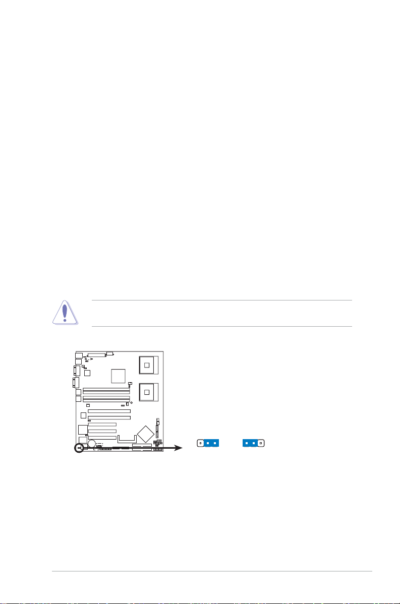
1.1.
Clear RTC RAM (CLRTC1)Clear RTC RAM (CLRTC1)
1.
Clear RTC RAM (CLRTC1)
1.1.
Clear RTC RAM (CLRTC1)Clear RTC RAM (CLRTC1)
This jumper allows you to clear the Real Time Clock (RTC) RAM in
CMOS. You can clear the CMOS memory of date, time, and system
setup parameters by erasing the CMOS RTC RAM data. The onboard
button cell battery powers the RAM data in CMOS, which include
system setup information such as system passwords.
To erase the RTC RAM:
1. Turn OFF the computer and unplug the power cord.
2. Remove the onboard battery.
3. Move the jumper cap from pins 1-2 (default) to pins 2-3. Keep the
cap on pins 2-3 for about 5~10 seconds, then move the cap back
to pins 1-2.
4. Re-install the battery.
5. Plug the power cord and turn ON the computer.
6. Hold down the <Del> key during the boot process and enter BIOS
setup to re-enter data.
Except when clearing the RTC RAM, never remove the cap on CLRTC
jumper default position. Removing the cap will cause system boot failure!
NCCH-DR
NCCH-DR Clear RTC RAM
ASUS AP1600R-E2 (AA2/AI2)ASUS AP1600R-E2 (AA2/AI2)
ASUS AP1600R-E2 (AA2/AI2)
ASUS AP1600R-E2 (AA2/AI2)ASUS AP1600R-E2 (AA2/AI2)
Normal
(Default)
CLRTC1
12
23
Clear CMOS
4-54-5
4-5
4-54-5

2.2.
CPU fan pin selection (3-pin FM_CPU1, FM_CPU2)CPU fan pin selection (3-pin FM_CPU1, FM_CPU2)
2.
CPU fan pin selection (3-pin FM_CPU1, FM_CPU2)
2.2.
CPU fan pin selection (3-pin FM_CPU1, FM_CPU2)CPU fan pin selection (3-pin FM_CPU1, FM_CPU2)
These jumpers allow you to connect either a 3-pin or a 4-pin CPU fan
cable plug to the CPU fan connectors (CPU_FAN1, CPU_FAN2). Set
these jumpers to pins 1-2 if you are using a 3-pin fan cable plug, or to
pins 2-3 if you are using a 4-pin plug.
FM_CPU2
2
1
DC mode PWM
(Default)
3
2
FM_CPU1
12
NCCH-DR
DC mode PWM
(Default)
23
NCCH-DR FM_CPU setting
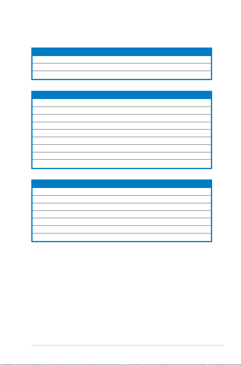
3.3.
USB device wake-up (3-pin USBPW12, USBPW34)USB device wake-up (3-pin USBPW12, USBPW34)
3.
USB device wake-up (3-pin USBPW12, USBPW34)
3.3.
USB device wake-up (3-pin USBPW12, USBPW34)USB device wake-up (3-pin USBPW12, USBPW34)
Set these jumpers to +5V to wake up the computer from S1 sleep
mode (CPU stopped, DRAM refreshed, system running in low power
mode) using the connected USB devices. Set to +5VSB to wake up
from S3 and S4 sleep modes (no power to CPU, DRAM in slow refresh,
power supply in reduced power mode).
USBPW12
12
+5V +5VSB
(Default)
USBPW34
12
NCCH-DR
NCCH-DR USB device wake-up
+5V +5VSB
(Default)
• The USB device wake-up feature requires a power supply that can
provide 500mA on the +5VSB lead for each USB port; otherwise, the
system would not power up.
• The total current consumed must NOT exceed the power supply
capability (+5VSB) whether under normal condition or in sleep mode.
23
23
4-64-6
4-6
4-64-6
Chapter 4: Motherboard informationChapter 4: Motherboard information
Chapter 4: Motherboard information
Chapter 4: Motherboard informationChapter 4: Motherboard information
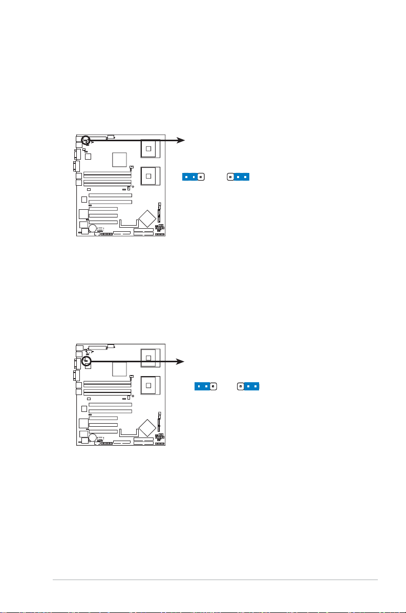
4.4.
Keyboard power (3-pin KBPWR1)Keyboard power (3-pin KBPWR1)
4.
Keyboard power (3-pin KBPWR1)
4.4.
Keyboard power (3-pin KBPWR1)Keyboard power (3-pin KBPWR1)
This jumper allows you to enable or disable the keyboard wake-up
feature. Set this jumper to pins 2-3 (+5VSB) to wake up the computer
when you press a key on the keyboard (the default is the Space Bar).
This feature requires an ATX power supply that can supply at least 1A
on the +5VSB lead, and a corresponding setting in the BIOS.
KBPWR1
12
+5V +5VSB
(Default)
NCCH-DR
23
NCCH-DR Keyboard power setting
5.5.
Gigabit LAN1 controller setting (3-pin LAN_EN1)Gigabit LAN1 controller setting (3-pin LAN_EN1)
5.
Gigabit LAN1 controller setting (3-pin LAN_EN1)
5.5.
Gigabit LAN1 controller setting (3-pin LAN_EN1)Gigabit LAN1 controller setting (3-pin LAN_EN1)
This jumper allows you to enable or disable the Intel® 82547GI Gigabit
LAN controller (CSA) that controls the LAN1 port. Place a jumper cap
on pins 1-2 to activate the Gigabit LAN1 controller.
NCCH-DR
NCCH-DR LAN_EN1 setting
ASUS AP1600R-E2 (AA2/AI2)ASUS AP1600R-E2 (AA2/AI2)
ASUS AP1600R-E2 (AA2/AI2)
ASUS AP1600R-E2 (AA2/AI2)ASUS AP1600R-E2 (AA2/AI2)
12
Enable
(Default)
LAN_EN1
Disable
23
4-74-7
4-7
4-74-7

6.6.
Gigabit LAN2 controller setting (3-pin LAN_EN2)Gigabit LAN2 controller setting (3-pin LAN_EN2)
6.
Gigabit LAN2 controller setting (3-pin LAN_EN2)
6.6.
Gigabit LAN2 controller setting (3-pin LAN_EN2)Gigabit LAN2 controller setting (3-pin LAN_EN2)
®
This jumper allows you to enable or disable the Intel
82541GI Gigabit
LAN controller (32-bit) that controls the LAN2 port. Place a jumper
cap on pins 1-2 to activate the Gigabit LAN2 controller.
LAN_EN2
12
Enable
NCCH-DR
(Default)
23
Disable
NCCH-DR LAN_EN2 setting
7.7.
Integrated graphics controller (3-pin VGA_EN1)Integrated graphics controller (3-pin VGA_EN1)
7.
Integrated graphics controller (3-pin VGA_EN1)
7.7.
Integrated graphics controller (3-pin VGA_EN1)Integrated graphics controller (3-pin VGA_EN1)
This jumper allows you enable or disable the onboard graphics
controller.
4-84-8
4-8
4-84-8
NCCH-DR
NCCH-DR VGA setting
VGA_EN1
12
Enable
(Default)
Chapter 4: Motherboard informationChapter 4: Motherboard information
Chapter 4: Motherboard information
Chapter 4: Motherboard informationChapter 4: Motherboard information
23
Disable
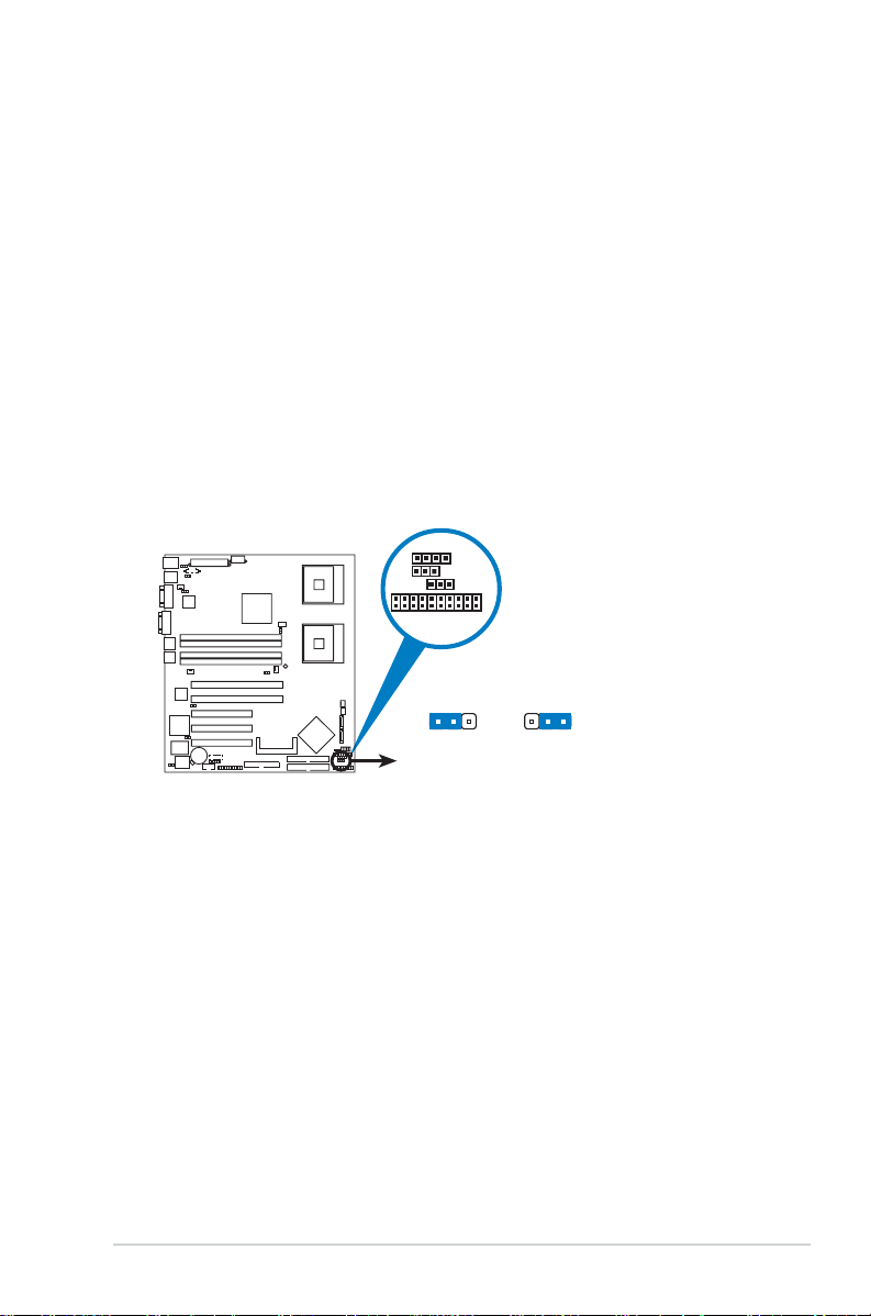
8.8.
Force BIOS recovery (3-pin RECOVERY)Force BIOS recovery (3-pin RECOVERY)
8.
Force BIOS recovery (3-pin RECOVERY)
8.8.
Force BIOS recovery (3-pin RECOVERY)Force BIOS recovery (3-pin RECOVERY)
This jumper allows you to update or recover the BIOS settings when it
gets corrupted or destroyed.This jumper allows you to update/recover
the BIOS quickly.
To update the BIOS:
1. Prepare a floppy disk that contains the latest BIOS for the
motherboard (xxxx-xxx.BIN) and the AWDFLASH.EXE utility.
2. Set the jumper to pins 2-3.
3. Insert the floppy disk, then turn on the system to update the BIOS.
4. Shut down the system.
5. Set the jumper back to pins 1-2.
6. Turn on the system.
LED
RECOVERY
0 LED1
PANEL1
RECOVERY
23
NCCH-DR
NCCH-DR BIOS recovery setting
12
Normal BIOS Recovery
(Default)
ASUS AP1600R-E2 (AA2/AI2)ASUS AP1600R-E2 (AA2/AI2)
ASUS AP1600R-E2 (AA2/AI2)
ASUS AP1600R-E2 (AA2/AI2)ASUS AP1600R-E2 (AA2/AI2)
4-94-9
4-9
4-94-9

4.3 Connectors
1.1.
Floppy disk drive connector (34-1 pin FLOPPY)Floppy disk drive connector (34-1 pin FLOPPY)
1.
Floppy disk drive connector (34-1 pin FLOPPY)
1.1.
Floppy disk drive connector (34-1 pin FLOPPY)Floppy disk drive connector (34-1 pin FLOPPY)
This connector is for the provided floppy disk drive (FDD) signal cable.
Insert one end of the cable to this connector, then connect the other
end to the signal connector at the back of the floppy disk drive.
Pin 5 on the connector is removed to prevent incorrect cable connection
when using a FDD cable with a covered Pin 5.
FLOPPY
PIN 1
NOTE: Orient the red markings on
NCCH-DR
NCCH-DR Floppy disk drive connector
2.2.
IDE connectors (40-1 pin PRI_IDE, SEC_IDE)IDE connectors (40-1 pin PRI_IDE, SEC_IDE)
2.
IDE connectors (40-1 pin PRI_IDE, SEC_IDE)
2.2.
IDE connectors (40-1 pin PRI_IDE, SEC_IDE)IDE connectors (40-1 pin PRI_IDE, SEC_IDE)
These connectors are for Ultra DMA 100/66/33 signal cables. The Ultra
DMA 100/66/33 signal cable has three connectors: a blue connector for
the primary IDE connector on the motherboard, a gray connector for an
Ultra DMA 100/66 IDE master device (hard disk drive), and a black
connector for an Ultra DMA 100/66/33 IDE slave device (optical drive/
hard disk drive). If you install two hard disk drives, you must configure
the second drive as a slave device by setting its jumper accordingly.
Refer to the hard disk documentation for the jumper settings.
the floppy ribbon cable to PIN 1.
4-104-10
4-10
4-104-10
• Pin 20 on the IDE connectors are removed to match the covered
hole on the Ultra DMA cable connector. This prevents incorrect
insertion when you connect the IDE cable.
• Use the 80-conductor IDE cable for Ultra DMA 100/66/33 IDE devices.
SEC_IDE
PIN 1
PRI_IDE
PIN 1
NOTE: Orient the red markings
NCCH-DR
(usually zigzag) on the IDE
ribbon cable to PIN 1.
NCCH-DR IDE connectors
Chapter 4: Motherboard informationChapter 4: Motherboard information
Chapter 4: Motherboard information
Chapter 4: Motherboard informationChapter 4: Motherboard information

3.3.
Serial ATA connectors (7-pin SATA1, SATA2)Serial ATA connectors (7-pin SATA1, SATA2)
3.
Serial ATA connectors (7-pin SATA1, SATA2)
3.3.
Serial ATA connectors (7-pin SATA1, SATA2)Serial ATA connectors (7-pin SATA1, SATA2)
These connectors are for the Serial ATA signal cables for Serial ATA
hard disk drives.
If you installed Serial ATA hard disk drives, you can create a RAID 0 or
RAID 1 configuration.
These connectors are set to
SS
tandard IDE tandard IDE
S
tandard IDE mode, you can connect Serial ATA boot/data hard disk
SS
tandard IDE tandard IDE
Standard IDE Standard IDE
Standard IDE mode by default. In
Standard IDE Standard IDE
drives to these connectors. If you intend to create a Serial ATA RAID set
SATA SATA
ModeMode
using these connectors, set the
SATA
SATA SATA
Mode
item in the BIOS to [RAID].
ModeMode
See page 5-28 and 5-29 for details.
SATA2
GND
RSATA_TXP2
RSATA_TXN2
GND
RSATA_RXN2
RSATA_RXP2
GND
SATA1
GND
RSATA_TXP1
RSATA_TXN1
GND
NCCH-DR
RSATA_RXN1
RSATA_RXP1
GND
NCCH-DR SATA connectors
Important notes on Serial ATAImportant notes on Serial ATA
Important notes on Serial ATA
Important notes on Serial ATAImportant notes on Serial ATA
• You must install Windows® 2000 Service Pack 4 or the Windows® XP
Service Pack 1 before using Serial ATA hard disk drives. The Serial
ATA RAID feature (RAID 0/RAID 1) is available only if you are using
Windows® 2000/XP.
• Use only two Serial ATA RAID connectors for each RAID 0 or RAID 1
set.
S S
• When using the connectors in
tandard IDE tandard IDE
S
tandard IDE mode, connect the
S S
tandard IDE tandard IDE
primary (boot) hard disk drive to the SATA1 or SATA2 connector.
Refer to the table below for the recommended SATA hard disk drive
connections.
Serial ATA hard disk drive connectionSerial ATA hard disk drive connection
Serial ATA hard disk drive connection
Serial ATA hard disk drive connectionSerial ATA hard disk drive connection
ConnectorConnector
Connector
ConnectorConnector
SATA1SATA1
SATA1
SATA1SATA1
SATA2SATA2
SATA2
SATA2SATA2
ASUS AP1600R-E2 (AA2/AI2)ASUS AP1600R-E2 (AA2/AI2)
ASUS AP1600R-E2 (AA2/AI2)
ASUS AP1600R-E2 (AA2/AI2)ASUS AP1600R-E2 (AA2/AI2)
SettingSetting
Setting
SettingSetting
MasterMaster
Master
MasterMaster
SlaveSlave
Slave
SlaveSlave
UseUse
Use
UseUse
Boot diskBoot disk
Boot disk
Boot diskBoot disk
Data diskData disk
Data disk
Data diskData disk
4-114-11
4-11
4-114-11

4.4.
Hard disk activity LED connector (4-pin HDLED1)Hard disk activity LED connector (4-pin HDLED1)
4.
Hard disk activity LED connector (4-pin HDLED1)
4.4.
Hard disk activity LED connector (4-pin HDLED1)Hard disk activity LED connector (4-pin HDLED1)
For some storage cards, such as SCSI card, with access signals for
external LEDs, this connector allows the access signals to go through
the front panel IDE_LED lead.
HDLED1
1
NC
NC
NCCH-DR
NCCH-DR
ADD_IN_CARD_ACT#
ADD_IN_CARD_ACT#
SCSI/SATA card activity LED connector
5.5.
CPU and system fan connectors (4-pin CPU_FAN1/2,CPU and system fan connectors (4-pin CPU_FAN1/2,
5.
CPU and system fan connectors (4-pin CPU_FAN1/2,
5.5.
CPU and system fan connectors (4-pin CPU_FAN1/2,CPU and system fan connectors (4-pin CPU_FAN1/2,
3-pin REAR_FAN1/2, FRNT_FAN1/2)3-pin REAR_FAN1/2, FRNT_FAN1/2)
3-pin REAR_FAN1/2, FRNT_FAN1/2)
3-pin REAR_FAN1/2, FRNT_FAN1/2)3-pin REAR_FAN1/2, FRNT_FAN1/2)
The fan connectors support cooling fans of 350 mA ~ 740 mA (8.88 W
max.) or a total of 2.1 A ~ 4.44 A (53.28 W max.) at +12V. Connect
the fan cables to the fan connectors on the motherboard, making sure
that the black wire of each cable matches the ground pin of the
connector.
Do not forget to connect the fan cables to the fan connectors.
Insufficient air flow inside the system may damage the motherboard
components. These are not jumpers! Do not place jumper caps on the
fan connectors!
CPU_FAN2
GND
Rotation
FANOUT6
FANPWR3
REAR_FAN2REAR_FAN1
Rotation
+12V
GND
GND
+12V
Rotation
NCCH-DR
NCCH-DR Fan connectors
CPU_FAN1
GND
FANPWR2
Rotation
FANOUT4
GND
+12V
Rotation
FRNT_FAN1 FRNT_FAN2
GND
+12V
Rotation
4-124-12
4-12
4-124-12
Chapter 4: Motherboard informationChapter 4: Motherboard information
Chapter 4: Motherboard information
Chapter 4: Motherboard informationChapter 4: Motherboard information

6.6.
USB port connector (10-1 pin USB34)USB port connector (10-1 pin USB34)
6.
USB port connector (10-1 pin USB34)
6.6.
USB port connector (10-1 pin USB34)USB port connector (10-1 pin USB34)
This connector is for additional USB 2.0 ports. Connect the USB
module cable to this connector, then install the module to a slot
opening at the back of the system chassis.
Never connect a
1394 cable1394 cable
1394 cable to the USB connectors. Doing so will
1394 cable1394 cable
damage the motherboard!
USB+5V
USB_P4-
USB_P4+
GND
NC
USB34
NCCH-DR
NCCH-DR USB 2.0 connector
USB+5V
USB_P3-
USB_P3+
GND
The USB port module is purchased separately.
7.7.
Serial port connector (10-1 pin COM2)Serial port connector (10-1 pin COM2)
7.
Serial port connector (10-1 pin COM2)
7.7.
Serial port connector (10-1 pin COM2)Serial port connector (10-1 pin COM2)
This connector is for a serial (COM) port. Connect the serial port
module cable to this connector, then install the module to a slot
opening at the back of the system chassis.
NCCH-DR
NCCH-DR
Serial port2 (COM2) connector
The serial port module is purchased separately.
ASUS AP1600R-E2 (AA2/AI2)ASUS AP1600R-E2 (AA2/AI2)
ASUS AP1600R-E2 (AA2/AI2)
ASUS AP1600R-E2 (AA2/AI2)ASUS AP1600R-E2 (AA2/AI2)
COM2
PIN 1
4-134-13
4-13
4-134-13

8.8.
SSI SSI
8.
8.8.
power connectors (24-pin ATXPWR1,power connectors (24-pin ATXPWR1,
SSI
power connectors (24-pin ATXPWR1,
SSI SSI
power connectors (24-pin ATXPWR1,power connectors (24-pin ATXPWR1,
8 8
8
8 8
-pin -pin
ATX12V1ATX12V1
-pin
ATX12V1
-pin -pin
ATX12V1ATX12V1
These connectors are for SSI power supply plugs. The power supply
plugs are designed to fit these connectors in only one orientation.
Find the proper orientation and push down firmly until the connectors
completely fit.
• Use of an SSI 12 V Specification 2.0-compliant power supply unit
(PSU) that provides a minimum power of 450 W is recommended
for a fully-configured system.
• Do not forget to connect the 8-pin ATX +12 V power plug;
otherwise, the system will not boot up.
• Use of a PSU with a higher power output is recommended when
configuring a system with more power consuming devices. The
system may become unstable or may not boot up if the power is
inadequate.
• You must install a PSU with a higher power rating if you intend to
install additional devices.
))
)
))
4-144-14
4-14
4-144-14
NCCH-DR
NCCH-DR Power connectors
24-pin Power Connector
+3 Volts
+3 Volts
Ground
+5 Volts
+5 Volts
Ground
Ground
Power OK
+5V Standby
+12 Volts
+12 Volts
+3 Volts
1
Ground
PSON#
Ground
Ground
-5 Volts
+5 Volts
+5 Volts
+5 Volts
Ground
Ground
+3 Volts
-12 Volts
Chapter 4: Motherboard informationChapter 4: Motherboard information
Chapter 4: Motherboard information
Chapter 4: Motherboard informationChapter 4: Motherboard information
8-pin
GND+12V CPU2
GND+12V CPU1
GND+12V CPU1
For Power Supply
with 20-pin
Power Connector
GND+12V CPU2

9.9.
Printer port connector (26-1 pin LPT1)Printer port connector (26-1 pin LPT1)
9.
Printer port connector (26-1 pin LPT1)
9.9.
Printer port connector (26-1 pin LPT1)Printer port connector (26-1 pin LPT1)
This connector is for a parallel printer port. Connect the parallel printer
port module cable to this connector, then install the module to a slot
opening at the back of the system chassis.
SPD4 GND
SPD5 GND
SPD6 GND
SPD7 GND
ACK# GND
GND
BUSY
PE GND
SLCT
LPT1
Pin 1
STB# AFD#
SPD3 GND
SPD2 SLIN#
SPD1 PINIT#
NCCH-DR
SPD0 ERROR#
NCCH-DR Parallel port connector
10.10.
BMC connector (16-pin BMCCONN1)BMC connector (16-pin BMCCONN1)
10.
BMC connector (16-pin BMCCONN1)
10.10.
BMC connector (16-pin BMCCONN1)BMC connector (16-pin BMCCONN1)
This connector is for the optional ASUS server management card.
+5VSB
+5VSB
BMC_LANCLK#
BMC_SMBCLK#
PSON#
BMC_RSTBTN#
PWROK
+5VSB
BMC_PWRBTN#
BMC_LANDATA#
BMC_SMBDATA#
PSONEN
GND
SMIOUT#
PRESENCE#
1
BMCCONN1
2
+5VSB
NCCH-DR
NCCH-DR BMC connector
ASUS AP1600R-E2 (AA2/AI2)ASUS AP1600R-E2 (AA2/AI2)
ASUS AP1600R-E2 (AA2/AI2)
ASUS AP1600R-E2 (AA2/AI2)ASUS AP1600R-E2 (AA2/AI2)
4-154-15
4-15
4-154-15

11.11.
Backplane SMBus connector (6-1 pin BPSMB1)Backplane SMBus connector (6-1 pin BPSMB1)
11.
Backplane SMBus connector (6-1 pin BPSMB1)
11.11.
Backplane SMBus connector (6-1 pin BPSMB1)Backplane SMBus connector (6-1 pin BPSMB1)
This connector allows you to connect SMBus (System Management
Bus) devices. Devices communicate with an SMBus host and/or other
SMBus devices using the SMBus interface.
BPSMB1
1
+5V
NCCH-DR
NCCH-DR SMBus connector
12.12.
Power supply SMBus connector (5-pin PSUSMB1)Power supply SMBus connector (5-pin PSUSMB1)
12.
Power supply SMBus connector (5-pin PSUSMB1)
12.12.
Power supply SMBus connector (5-pin PSUSMB1)Power supply SMBus connector (5-pin PSUSMB1)
FAN_PWM
I2C_6_CLK#
GND
I2C_6_DATA#
This connects SMBus (System Management Bus) devices to the power
supply unit. Devices communicate with an SMBus host and/or other
SMBus devices using the SMBus interface.
PSUSMB1
4-164-16
4-16
4-164-16
NC
GND
PSU_I2CCLK
PSU_I2CDATA
+3.3V Remote Sense
NCCH-DR
NCCH-DR Power supply SMBus connector
Chapter 4: Motherboard informationChapter 4: Motherboard information
Chapter 4: Motherboard information
Chapter 4: Motherboard informationChapter 4: Motherboard information

13.13.
Auxilliary panel connector (20-2 pin AUX_PANEL1)Auxilliary panel connector (20-2 pin AUX_PANEL1)
13.
Auxilliary panel connector (20-2 pin AUX_PANEL1)
13.13.
Auxilliary panel connector (20-2 pin AUX_PANEL1)Auxilliary panel connector (20-2 pin AUX_PANEL1)
This connector supports several front panel chassis-mounted
functions including chassis intrusion, LAN1/LAN2 link and activity
LEDs, Locator LED1/2, Locator switch, and front panel System
Management bus (SMBus).
AUX_PANEL1
I2CDATALOCLED1+
+5VSBLOCLED1-
LANACT1
LANLINK1
I2CDATA
GNDGND
LANLINK2
LANACT2
1
+5VSB
NCCH-DR
INTTUDER
GND
LOCBTN#
LOCLED2-
LOCLED2+
NCCH-DR Auxiliary panel connector
14.14.
System panel connector (20-pin PANEL1)System panel connector (20-pin PANEL1)
14.
System panel connector (20-pin PANEL1)
14.14.
System panel connector (20-pin PANEL1)System panel connector (20-pin PANEL1)
This connector supports several chassis-mounted functions.
MLED-GND
NCPWRBTN#
+5VGND
PLED-
MLED+NMIBTN#
GNDNC
GNDFP_RESET#
SPKROUTGND
PLED+HDLED+
NCGND
PANEL1
NCCH-DR
NCCH-DR System panel connector
The sytem panel connector is color-coded for easy connection. Refer to
the connector descriptions on the next page for details.
ASUS AP1600R-E2 (AA2/AI2)ASUS AP1600R-E2 (AA2/AI2)
ASUS AP1600R-E2 (AA2/AI2)
ASUS AP1600R-E2 (AA2/AI2)ASUS AP1600R-E2 (AA2/AI2)
4-174-17
4-17
4-174-17

System power LED (Green 3-pin PLED)System power LED (Green 3-pin PLED)
•
System power LED (Green 3-pin PLED)
System power LED (Green 3-pin PLED)System power LED (Green 3-pin PLED)
This 3-pin connector is for the system power LED. Connect the
chassis power LED cable to this connector. The system power LED
lights up when you turn on the system power, and blinks when the
system is in sleep mode.
Message LED (Brown 2-pin MLED)Message LED (Brown 2-pin MLED)
•
Message LED (Brown 2-pin MLED)
Message LED (Brown 2-pin MLED)Message LED (Brown 2-pin MLED)
This connector is for the message LED cable that connects to the
front panel message LED. The message LED indicates the booting
status. The LED blinks when the system is in the boot process until
the operating system is loaded.
System warning speaker (Orange 4-pin SPEAKER)System warning speaker (Orange 4-pin SPEAKER)
•
System warning speaker (Orange 4-pin SPEAKER)
System warning speaker (Orange 4-pin SPEAKER)System warning speaker (Orange 4-pin SPEAKER)
This 4-pin connector is for the chassis-mounted system warning
speaker. The speaker allows you to hear system beeps and warnings.
Hard disk drive activity LED (Red 2-pin HDD LED)Hard disk drive activity LED (Red 2-pin HDD LED)
•
Hard disk drive activity LED (Red 2-pin HDD LED)
Hard disk drive activity LED (Red 2-pin HDD LED)Hard disk drive activity LED (Red 2-pin HDD LED)
This 2-pin connector is for the HDD Activity LED. Connect the HDD
Activity LED cable to this connector. The IDE LED lights up or flashes
when data is read from or written to the HDD.
ATX power button/soft-off button (Yellow 2-pin PWRSW)ATX power button/soft-off button (Yellow 2-pin PWRSW)
•
ATX power button/soft-off button (Yellow 2-pin PWRSW)
ATX power button/soft-off button (Yellow 2-pin PWRSW)ATX power button/soft-off button (Yellow 2-pin PWRSW)
This connector is for the system power button. Pressing the power
button turns the system on or puts the system in sleep or soft-off
mode depending on the BIOS settings. Pressing the power switch for
more than four seconds while the system is ON turns the system OFF.
Reset button (Blue 2-pin RESET)Reset button (Blue 2-pin RESET)
•
Reset button (Blue 2-pin RESET)
Reset button (Blue 2-pin RESET)Reset button (Blue 2-pin RESET)
This 2-pin connector is for the chassis-mounted reset button for
system reboot without turning off the system power.
4-184-18
4-18
4-184-18
Chapter 4: Motherboard informationChapter 4: Motherboard information
Chapter 4: Motherboard information
Chapter 4: Motherboard informationChapter 4: Motherboard information

Chapter 5
This chapter lists the hardware
setup procedures that you have to
perform when installing or removing
system components.
ASUS AP1600R-E2 (AA2/AI2)ASUS AP1600R-E2 (AA2/AI2)
ASUS AP1600R-E2 (AA2/AI2)
ASUS AP1600R-E2 (AA2/AI2)ASUS AP1600R-E2 (AA2/AI2)
BIOS setup
2-1

5.1 Managing and updating your BIOS
The following utilities allow you to manage and update the motherboard
Basic Input/Output System (BIOS) setup.
Award BIOS Award BIOS
1.
Award BIOS Flash Utility (Updates the BIOS in DOS mode using a
Award BIOS Award BIOS
floppy disk.)
ASUS CrashFree BIOS 2 ASUS CrashFree BIOS 2
2.
ASUS CrashFree BIOS 2 (Updates the BIOS using a bootable
ASUS CrashFree BIOS 2 ASUS CrashFree BIOS 2
floppy disk or the motherboard support CD when the BIOS file fails or
gets corrupted.)
ASUS EZ Flash ASUS EZ Flash
3.
ASUS EZ Flash (Updates the BIOS in DOS mode using a floppy disk
ASUS EZ Flash ASUS EZ Flash
or the motherboard support CD.)
ASUS Update ASUS Update
4.
ASUS Update (Updates the BIOS in Windows
ASUS Update ASUS Update
Refer to the corresponding sections for details on these utilities.
Save a copy of the original motherboard BIOS file to a bootable floppy
disk in case you need to restore the BIOS in the future. Copy the original
motherboard BIOS using the ASUS Update or Award BIOS Flash utilities.
®
environment.)
5.1.15.1.1
5.1.1
5.1.15.1.1
Creating a bootable floppy diskCreating a bootable floppy disk
Creating a bootable floppy disk
Creating a bootable floppy diskCreating a bootable floppy disk
This barebone system does not include a floppy disk drive. Connect an
external floppy disk drive (USB interface) to any of the USB 2.0 ports on
the front or rear panel if you need to use a floppy disk.
1. Do either one of the following to create a bootable floppy disk.
DOS environment
a. Insert a 1.44MB floppy disk into the drive.
b. At the DOS prompt, type format A:/S
then press <Enter>.
Windows® XP environment
a. Insert a 1.44 MB floppy disk to the floppy disk drive.
b. Click
ComputerComputer
Computer.
ComputerComputer
Start Start
Start from the Windows® desktop, then select
Start Start
MyMy
My
MyMy
c. Select the 3 1/2 Floppy Drive icon.
d. Click
e.
File File
File from the menu, then select
File File
Floppy DiskFloppy Disk
Floppy Disk window appears.
Floppy DiskFloppy Disk
®®
®
®®
WindowsWindows
Windows
WindowsWindows
disk disk
disk from the format options field, then click
disk disk
XP users: XP users:
XP users: Select
XP users: XP users:
FormatFormat
Format. A
FormatFormat
Create an MS-DOS startupCreate an MS-DOS startup
Create an MS-DOS startup
Create an MS-DOS startupCreate an MS-DOS startup
Format 3 1/2Format 3 1/2
Format 3 1/2
Format 3 1/2Format 3 1/2
StartStart
Start.
StartStart
5-25-2
5-2
5-25-2
Chapter 5: BIOS setupChapter 5: BIOS setup
Chapter 5: BIOS setup
Chapter 5: BIOS setupChapter 5: BIOS setup

Windows® 2000 environment
To create a set of boot disks for Windows® 2000:
a. Insert a formatted, high density 1.44 MB floppy disk into the drive.
®
b. Insert the Windows
c. Click
d. In the
StartStart
Start, then select
StartStart
Open Open
Open field, type D:\bootdisk\makeboot a:
Open Open
2000 CD to the optical drive.
RunRun
Run.
RunRun
assuming that D is your optical drive letter.
e. Press <Enter>, then follow screen instructions to continue.
2. Copy the original or the latest motherboard BIOS file to the bootable
floppy disk.
ASUS AP1600R-E2 (AA2/AI2)ASUS AP1600R-E2 (AA2/AI2)
ASUS AP1600R-E2 (AA2/AI2)
ASUS AP1600R-E2 (AA2/AI2)ASUS AP1600R-E2 (AA2/AI2)
5-35-3
5-3
5-35-3

5.1.25.1.2
5.1.2
5.1.25.1.2
The Basic Input/Output System (BIOS) can be updated using the
AwardBIOS Flash Utility. The following sections tell you how to update the
BIOS or how to save the current BIOS file.
Updating the current BIOS fileUpdating the current BIOS file
Updating the current BIOS file
Updating the current BIOS fileUpdating the current BIOS file
To update the current BIOS file:
1. Download the latest BIOS file from the ASUS web site. Extract the
zipped file, then save it to a floppy disk as
2. Copy the AwardBIOS Flash Utility (awdflash.exe) from the Software
3. Boot the system in DOS mode using the bootable floppy disk you
4. When the A:> appears, replace the bootable floppy disk with the
5. At the prompt, type awdflash then press <Enter>. The Award BIOS
AwardBIOS Flash UtilityAwardBIOS Flash Utility
AwardBIOS Flash Utility
AwardBIOS Flash UtilityAwardBIOS Flash Utility
*.BIN*.BIN
*.BIN.
*.BIN*.BIN
Save only the updated BIOS file in the floppy disk to avoid loading the
wrong BIOS file.
folder of the support CD to the floppy disk with the latest BIOS file.
created earlier.
floppy disk containing the new BIOS file and the Award BIOS Flash
Utility.
Flash Utility screen appears.
5-45-4
5-4
5-45-4
AwardBIOS Flash Utility for ASUS V1.05
(C) Phoenix Technologies Ltd. All Rights Reserved
For Canterwood - NCCH-DRC-00 DATE: 07/14/2004
Flash Type - SST 49LF008A /3.3V
File Name to Program :
Message: Please input File Name!
Chapter 5: BIOS setupChapter 5: BIOS setup
Chapter 5: BIOS setup
Chapter 5: BIOS setupChapter 5: BIOS setup
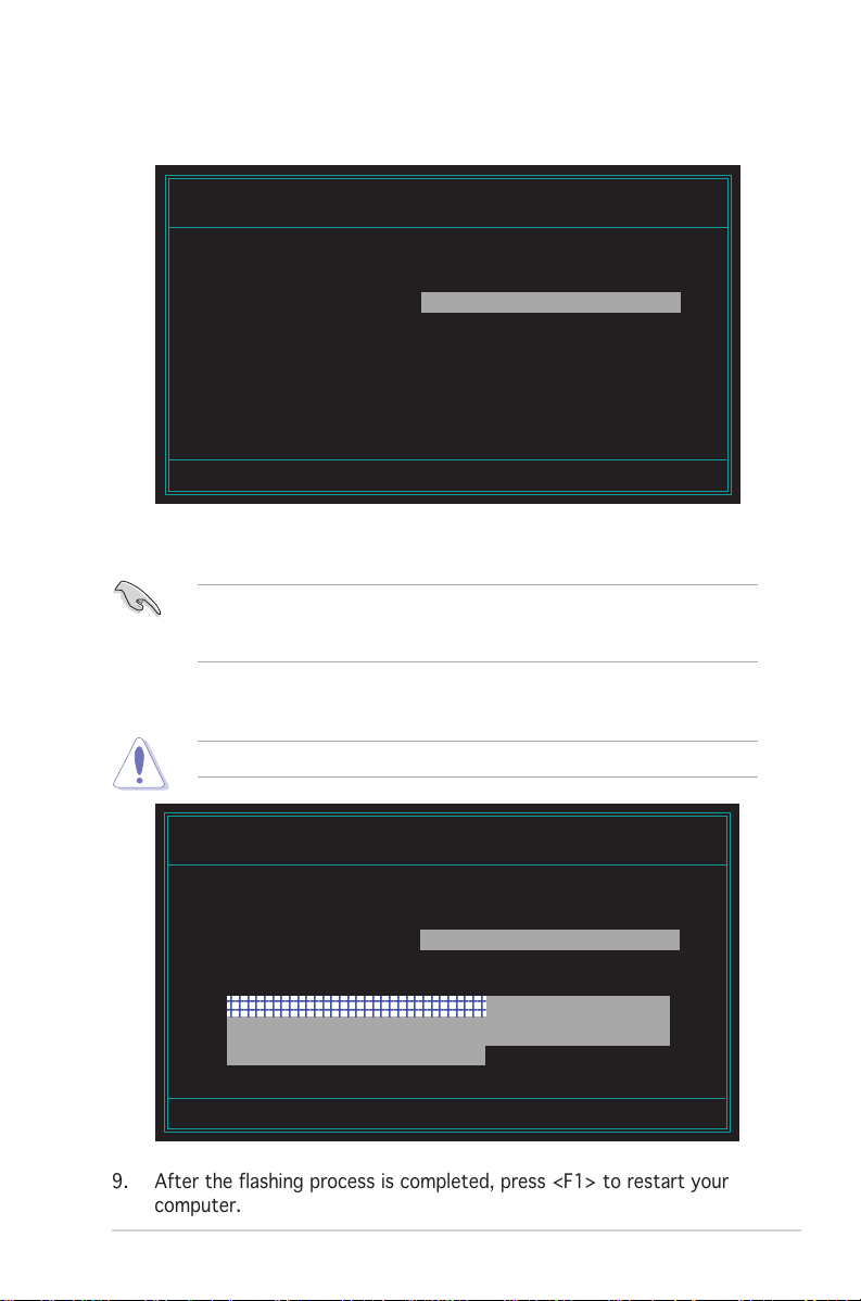
6. Type the BIOS file name in the File Name to Program field, then press
2
2
<Enter>.
AwardBIOS Flash Utility for ASUS V1.05
(C) Phoenix Technologies Ltd. All Rights Reserved
For Canterwood - NCCH-DRC-00 DATE: 07/14/2004
Flash Type - SST 49LF008A /3.3V
File Name to Program : 1001.bin
Message: Do You Want To Save BIOS (Y/N)
7. The utility prompts you to save the current BIOS file. Press <Y> to
save the current BIOS file to the floppy disk, or <N> to continue.
If you intend to save the current BIOS file, make sure that the floppy
disk has enough disk space to save the file. See the next section for
details on saving the current BIOS file.
8. The utility verifies the BIOS file in the floppy disk and starts flashing
the BIOS file.
Do not turn off or reset the system during the flashing process!
AwardBIOS Flash Utility for ASUS V1.05
(C) Phoenix Technologies Ltd. All Rights Reserved
For Canterwood - NCCH-DRC-00 DATE: 07/14/2004
Flash Type - SST 49LF008A /3.3V
File Name to Program : 1001.bin
Program Flashing Memory - 0FE00 OK
234567890123456789012345678901
234567890123456789012345678901
Write OK No Update Write Fail
Warning: Don’t Turn Off Power Or Reset System!
9. After the flashing process is completed, press <F1> to restart your
computer.
ASUS AP1600R-E2 (AA2/AI2)ASUS AP1600R-E2 (AA2/AI2)
ASUS AP1600R-E2 (AA2/AI2)
ASUS AP1600R-E2 (AA2/AI2)ASUS AP1600R-E2 (AA2/AI2)
5-55-5
5-5
5-55-5

Copying the current BIOS fileCopying the current BIOS file
Copying the current BIOS file
Copying the current BIOS fileCopying the current BIOS file
You can use the AwardBIOS Flash Utility to save the current BIOS file. You
can load the current BIOS file when the BIOS file gets corrupted during the
flashing process.
To save the current BIOS file using the AwardBIOS Flash Utility:
1. Follow steps 1 to 6 of the previous section.
2. Press <Y> when the utility prompts you to save the current BIOS file.
The following screen appears.
AwardBIOS Flash Utility for ASUS V1.05
(C) Phoenix Technologies Ltd. All Rights Reserved
For Canterwood - NCCH-DRC-00 DATE: 07/14/2004
Flash Type - SST 49LF008A /3.3V
File Name to Program : 1001.bin
Save current BIOS as :
Message:
3. Type a filename for the current BIOS file in the Save current BIOS as
field, then press <Enter>.
5-65-6
5-6
5-65-6
AwardBIOS Flash Utility for ASUS V1.05
(C) Phoenix Technologies Ltd. All Rights Reserved
For Canterwood - NCCH-DRC-00 DATE: 07/14/2004
Flash Type - SST 49LF008A /3.3V
File Name to Program : 1001.bin
Checksum : 0E00
Save current BIOS as : old.bin
Message: Please Wait!
Chapter 5: BIOS setupChapter 5: BIOS setup
Chapter 5: BIOS setup
Chapter 5: BIOS setupChapter 5: BIOS setup

12345678901234567890123456789012
1
2
12345678901234567890123456789012
4. The utility saves the current BIOS file to the floppy disk, then returns
to the BIOS flashing process.
AwardBIOS Flash Utility for ASUS V1.05
(C) Phoenix Technologies Ltd. All Rights Reserved
For Canterwood - NCCH-DRC-00 DATE: 07/14/2004
Flash Type - SST 49LF008A /3.3V
File Name to Program : 1001.bin
Now Backup System BIOS to
File!
234567890123456789012345678901
Message: Please Wait!Reset
ASUS AP1600R-E2 (AA2/AI2)ASUS AP1600R-E2 (AA2/AI2)
ASUS AP1600R-E2 (AA2/AI2)
ASUS AP1600R-E2 (AA2/AI2)ASUS AP1600R-E2 (AA2/AI2)
5-75-7
5-7
5-75-7
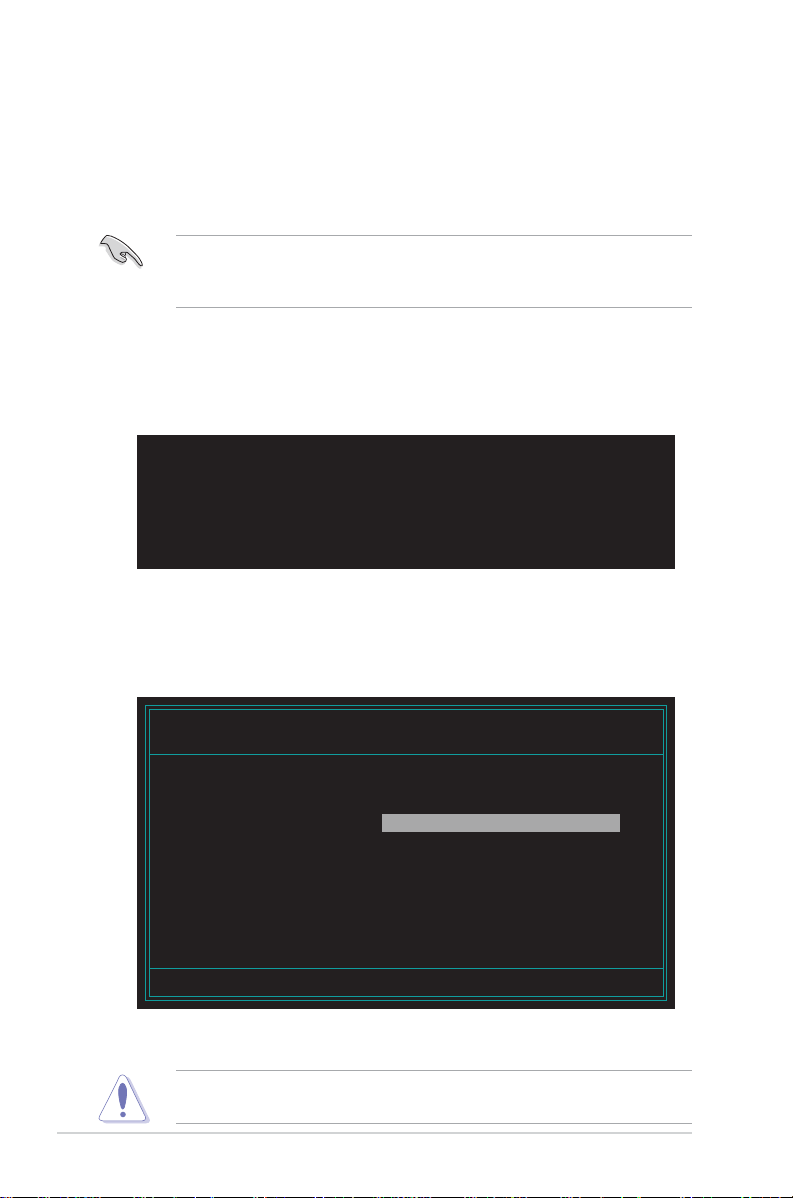
5.1.35.1.3
5.1.3
5.1.35.1.3
ASUS CrashFree BIOS 2 utilityASUS CrashFree BIOS 2 utility
ASUS CrashFree BIOS 2 utility
ASUS CrashFree BIOS 2 utilityASUS CrashFree BIOS 2 utility
The ASUS CrashFree BIOS 2 is an auto recovery tool that allows you to
restore the BIOS file when it fails or gets corrupted during the updating
process. You can update a corrupted BIOS file using the floppy disk that
contains the updated BIOS file and the AwardBIOS Flash Utility or the
motherboard support CD.
Prepare the floppy disk containing the updated motherboard BIOS and
the AwardBIOS Flash Utility or the motherboard support CD before using
this utility.
Recovering the BIOS from a floppy diskRecovering the BIOS from a floppy disk
Recovering the BIOS from a floppy disk
Recovering the BIOS from a floppy diskRecovering the BIOS from a floppy disk
To recover the BIOS from a floppy disk:
1. Turn on the system, then insert the bootable floppy disk to the floppy
disk drive. The following screen appears when the BIOS file is corrupted.
Award BootBlock BIOS v.1.0
Copyright (c) 2000, Award Software, Inc.
BIOS ROM checksum error
Detecting IDE ATAPI device...
Found CD-ROM, try to Boot from it ... Fail
Detecting floppy drive A media ....
INSERT SYSTEM DISK AND PRESS ENTER_
2. Press <Enter>. When the A:> appears, replace the bootable floppy disk
with the floppy disk containing the new BIOS file and the Award BIOS
Flash Utility.
3. At the prompt, type awdflash then press <Enter>. The Award BIOS
Flash Utility screen appears.
AwardBIOS Flash Utility for ASUS V1.05
(C) Phoenix Technologies Ltd. All Rights Reserved
For Canterwood - NCCH-DRC-00 DATE: 07/14/2004
Flash Type - SST 49LF008A /3.3V
File Name to Program :
Message: Please input File Name!
4. Update the BIOS file following the instructions on the section
“AwardBIOS Flash Utility”.
DO NOT shut down or reset the system while updating the BIOS! Doing
so can cause system boot failure!
5-85-8
5-8
5-85-8
Chapter 5: BIOS setupChapter 5: BIOS setup
Chapter 5: BIOS setup
Chapter 5: BIOS setupChapter 5: BIOS setup

Recovering the BIOS from the support CDRecovering the BIOS from the support CD
Recovering the BIOS from the support CD
Recovering the BIOS from the support CDRecovering the BIOS from the support CD
To recover the BIOS from the support CD:
1. Place the motherboard support CD to the optical drive, remove any
floppy disk from the floppy disk drive, then restart the system. The
following screen appears when the BIOS file is corrupted.
Award BootBlock BIOS v.1.0
Copyright (c) 2000, Award Software, Inc.
BIOS ROM checksum error
Detecting IDE ATAPI device...
Found CD-ROM, try to Boot from it ... Pass
1. FD 1.44MB System Type-(00)
Loading FreeDOS FAT KERNEL GO!
Press any key to boot from CDROM...
2. When prompted, press any key to boot from the CD. The CD loads the
boot files to the system, then prompts you to recover the BIOS file.
The BIOS was corrupted! Do you want to recover (y/n)?
3. Press <Y>. The following screen appears.
Would you like to FLASH bios now? (y/n)
Yes or No _
4. Press <Y>. The AwardBIOS Flash Utility appears.
AwardBIOS Flash Utility for ASUS V1.05
(C) Phoenix Technologies Ltd. All Rights Reserved
For Canterwood - NCCH-DRC-00 DATE: 07/14/2004
Flash Type - SST 49LF008A /3.3V
File Name to Program :
Message: Please input File Name!
The AwardBIOS Flash Utility searches the support CD for the updated
BIOS file. When found, the utility automatically updates the BIOS, then
restarts the system.
DO NOT shut down or reset the system while updating the BIOS! Doing
so can cause system boot failure!
ASUS AP1600R-E2 (AA2/AI2)ASUS AP1600R-E2 (AA2/AI2)
ASUS AP1600R-E2 (AA2/AI2)
ASUS AP1600R-E2 (AA2/AI2)ASUS AP1600R-E2 (AA2/AI2)
5-95-9
5-9
5-95-9

5.1.45.1.4
5.1.4
5.1.45.1.4
ASUS EZ Flash utilityASUS EZ Flash utility
ASUS EZ Flash utility
ASUS EZ Flash utilityASUS EZ Flash utility
The ASUS EZ Flash feature allows you to update the BIOS without having to
go through the long process of booting from a floppy disk and using a
DOS-based utility. The EZ Flash utility is built-in the BIOS chip so it is
accessible by pressing <Alt> + <F2> during the Power-On Self Tests
(POST).
To update the BIOS using EZ Flash:
1. Visit the ASUS website (www.asus.com) to download the latest BIOS
file for the motherboard.
2. Save the BIOS file to a floppy disk, then restart the system.
3. Press <Alt> + <F2> during POST to display the following.
Insert Disk press Enter or Esc to continue POST
4. Insert the floppy disk that contains the BIOS file to the floppy disk
drive, then press <Enter>. When the correct BIOS file is found,
EZ Flash opens the AwardBIOS Flash Utility.
The AwardBIOS Flash Utility searches the floppy disk for the updated
BIOS file. When found, the utility automatically updates the BIOS, then
restarts the system.
AwardBIOS Flash Utility for ASUS V1.05
(C) Phoenix Technologies Ltd. All Rights Reserved
For Canterwood - NCCH-DRC-00 DATE: 07/14/2004
Flash Type - SST 49LF008A /3.3V
File Name to Program : 1001.bin
5-105-10
5-10
5-105-10
• Do not shutdown or reset the system while updating the BIOS to
prevent system boot failure!
•A “Source File Not Found!” error message appears if the correct
BIOS file is not found in the floppy disk.
Chapter 5: BIOS setupChapter 5: BIOS setup
Chapter 5: BIOS setup
Chapter 5: BIOS setupChapter 5: BIOS setup

5.1.55.1.5
5.1.5
5.1.55.1.5
The ASUS Update is a utility that allows you to manage, save, and update
the motherboard BIOS in Windows® environment. The ASUS Update utility
allows you to:
This utility is available in the support CD that comes with the motherboard
package.
Installing ASUS UpdateInstalling ASUS Update
Installing ASUS Update
Installing ASUS UpdateInstalling ASUS Update
To install ASUS Update:
ASUS Update utilityASUS Update utility
ASUS Update utility
ASUS Update utilityASUS Update utility
• Save the current BIOS file
• Download the latest BIOS file from the Internet
• Update the BIOS from an updated BIOS file
• Update the BIOS directly from the Internet, and
• View the BIOS version information.
ASUS Update requires an Internet connection either through a network
or an Internet Service Provider (ISP).
1. Place the support CD in the optical drive. The
2. Click the
VX.XX.XXVX.XX.XX
VX.XX.XX.
VX.XX.XXVX.XX.XX
3. The ASUS Update utility is copied to your system.
ASUS AP1600R-E2 (AA2/AI2)ASUS AP1600R-E2 (AA2/AI2)
ASUS AP1600R-E2 (AA2/AI2)
ASUS AP1600R-E2 (AA2/AI2)ASUS AP1600R-E2 (AA2/AI2)
Utilities Utilities
Utilities tab, then click
Utilities Utilities
Quit all Windows® applications before you update the BIOS using this
utility.
Install ASUS UpdateInstall ASUS Update
Install ASUS Update
Install ASUS UpdateInstall ASUS Update
Drivers Drivers
Drivers menu appears.
Drivers Drivers
5-115-11
5-11
5-115-11
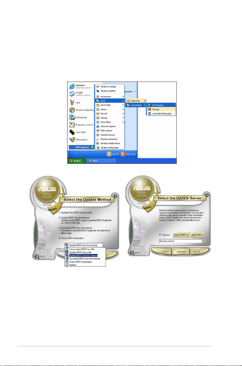
Updating the BIOS through the InternetUpdating the BIOS through the Internet
Updating the BIOS through the Internet
Updating the BIOS through the InternetUpdating the BIOS through the Internet
To update the BIOS through the Internet:
®
1. Launch the ASUS Update utility from the Windows
Start Start
Start >
Start Start
Programs Programs
Programs >
Programs Programs
ASUS ASUS
ASUS >
ASUS ASUS
ASUSUpdate ASUSUpdate
ASUSUpdate >
ASUSUpdate ASUSUpdate
desktop by clicking
ASUSUpdateASUSUpdate
ASUSUpdate. The
ASUSUpdateASUSUpdate
ASUS Update main window appears.
2. Select
5-125-12
5-12
5-125-12
Update BIOS fromUpdate BIOS from
Update BIOS from
Update BIOS fromUpdate BIOS from
the Internet the Internet
the Internet option from the
the Internet the Internet
drop-down menu, then click
NextNext
Next.
NextNext
3. Select the ASUS FTP site
nearest you to avoid network
traffic, or click
NextNext
Click
Next.
NextNext
Chapter 5: BIOS setupChapter 5: BIOS setup
Chapter 5: BIOS setup
Chapter 5: BIOS setupChapter 5: BIOS setup
Auto SelectAuto Select
Auto Select.
Auto SelectAuto Select
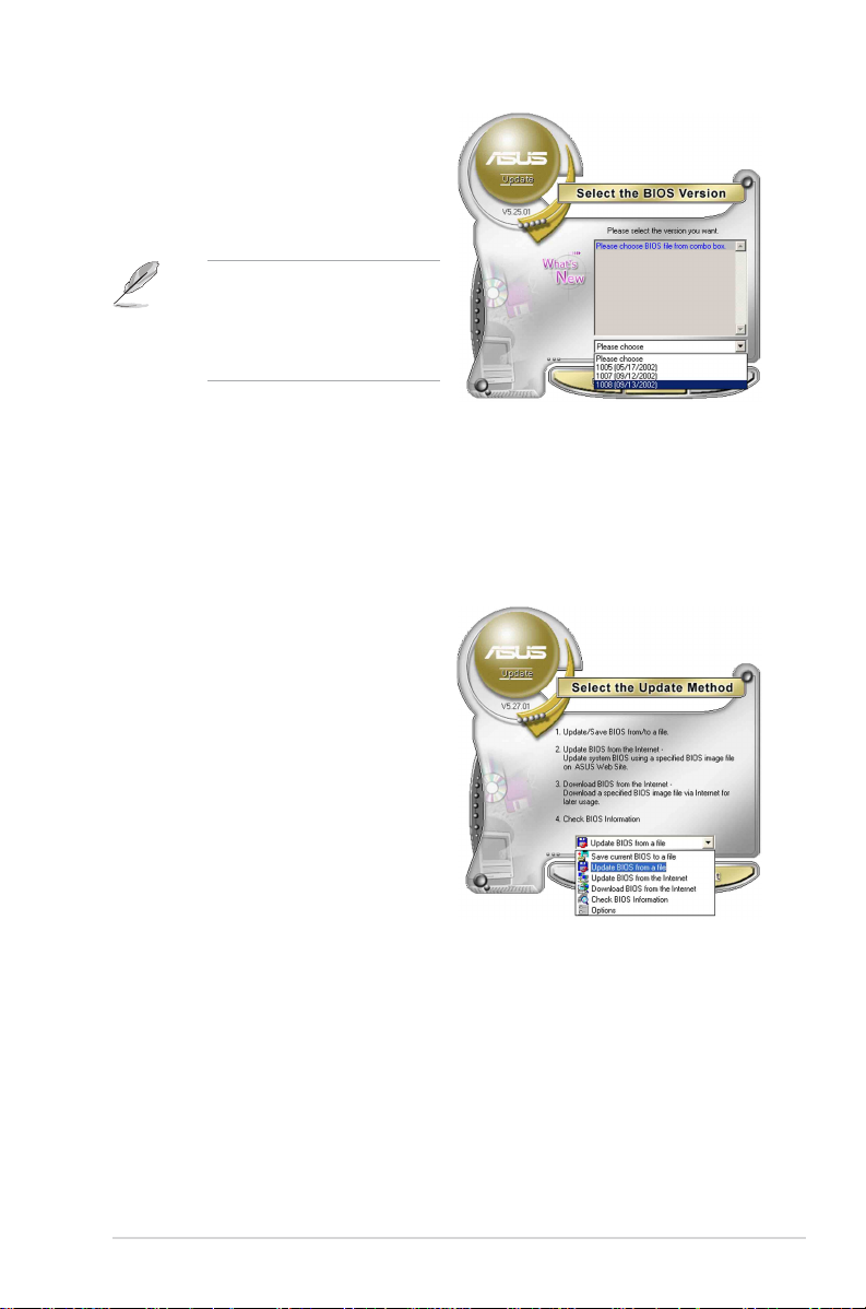
4. From the FTP site, select the
BIOS version that you wish to
download. Click Next.
5. Follow the screen instructions to
complete the update process.
The ASUS Update utility is
capable of updating itself
through the Internet. Always
update the utility to avail all
its features.
Updating the BIOS through a BIOS fileUpdating the BIOS through a BIOS file
Updating the BIOS through a BIOS file
Updating the BIOS through a BIOS fileUpdating the BIOS through a BIOS file
To update the BIOS through a BIOS file:
®
1. Launch the ASUS Update utility from the Windows
clicking
ASUSUpdateASUSUpdate
ASUSUpdate. The ASUS Update main window appears.
ASUSUpdateASUSUpdate
2. Select
file file
file option from the drop-down
file file
Start Start
Start >
Start Start
Update BIOS from aUpdate BIOS from a
Update BIOS from a
Update BIOS from aUpdate BIOS from a
menu, then click
Programs Programs
Programs >
Programs Programs
NextNext
Next.
NextNext
ASUS ASUS
ASUS >
ASUS ASUS
ASUSUpdate ASUSUpdate
ASUSUpdate >
ASUSUpdate ASUSUpdate
desktop by
3. Locate the BIOS file from the
Open Open
Open window, then click
Open Open
SaveSave
Save.
SaveSave
4. Follow the screen instructions to complete the update process.
ASUS AP1600R-E2 (AA2/AI2)ASUS AP1600R-E2 (AA2/AI2)
ASUS AP1600R-E2 (AA2/AI2)
ASUS AP1600R-E2 (AA2/AI2)ASUS AP1600R-E2 (AA2/AI2)
5-135-13
5-13
5-135-13

5.2 BIOS Setup program
This motherboard includes a Flash ROM that you can update using the
provided utility described in section “4.1 Managing and updating your
BIOS.”
Use the BIOS Setup program when you are installing a motherboard,
reconfiguring your system, or prompted to “Run Setup”. This section
explains how to configure your system using this utility.
Even if you are not prompted to use the Setup program, you may want to
change the configuration of your computer in the future. For example, you
may want to enable the security password feature or make changes to the
power management settings. This requires you to reconfigure your system
using the BIOS Setup program so that the computer can recognize these
changes and record them in the CMOS RAM of the Flash ROM.
The Flash ROM on the motherboard stores the Setup utility. When you start
up the computer, the system provides you with the opportunity to run this
program. Press <Delete> during the Power-On Self Test (POST) to enter
the Setup utility, otherwise, POST continues with its test routines.
If you wish to enter Setup after POST, restart the system by pressing
<Ctrl> + <Alt> + <Delete>, or by pressing the reset button on the system
chassis. You can also restart by turning the system off and then back on.
Do this last option only if the first two failed.
The Setup program is designed to make it as easy to use as possible. It is a
menu-driven program, which means you can scroll through the various
sub-menus and make your selections among the predetermined choices.
5-145-14
5-14
5-145-14
Because the BIOS software is constantly being updated, the following
BIOS setup screens and descriptions are for reference purposes only, and
may not exactly match what you see on your screen.
Chapter 5: BIOS setupChapter 5: BIOS setup
Chapter 5: BIOS setup
Chapter 5: BIOS setupChapter 5: BIOS setup
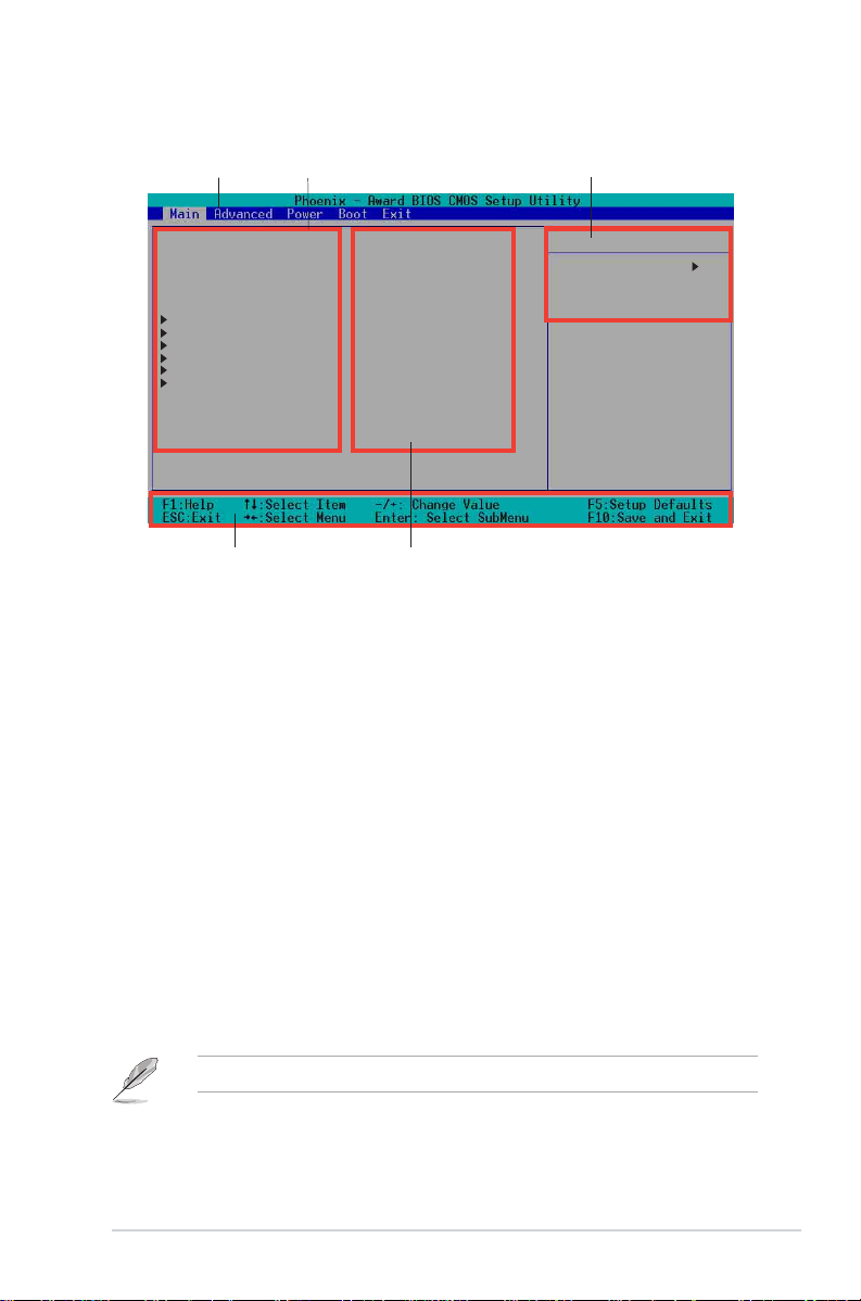
5.2.15.2.1
5.2.1
5.2.15.2.1
BIOS menu screenBIOS menu screen
BIOS menu screen
BIOS menu screenBIOS menu screen
Menu barMenu bar
Menu bar
Menu barMenu bar
System Time 11: 10 : 30
System Date Wed, Jul 21 2004
Legacy Diskette A [1.44M, 3.5 in.]
Floppy 3 Mode Support [Disabled]
Primary IDE Master [None]
Primary IDE Slave [None]
Secondary IDE Master [None]
Secondary IDE Slave [None]
Third IDE Master [None]
Fourth IDE Master [None]
Base Memory 640K
Extended Memory 260096K
Total Memory 261120K
Navigation keysNavigation keys
Navigation keys
Navigation keysNavigation keys
5.2.25.2.2
5.2.2
5.2.25.2.2
Menu itemsMenu items
Menu items
Menu itemsMenu items
Menu barMenu bar
Menu bar
Menu barMenu bar
Field settingsField settings
Field settings
Field settingsField settings
General helpGeneral help
General help
General helpGeneral help
Select Menu
Item Specific Help
Change the internal
clock.
The menu bar on top of the screen has the following main items:
MainMain
Main For changing the basic system configuration settings
MainMain
AdvancedAdvanced
Advanced For changing the advanced system settings
AdvancedAdvanced
PowerPower
Power For changing the power configuration settings
PowerPower
BootBoot
Boot For changing the system boot configuration settings
BootBoot
ExitExit
Exit For selecting the exit options and loading default settings
ExitExit
To select the menu bar items, press the right or left arrow key on the
keyboard until the desired item is highlighted.
5.2.35.2.3
5.2.3
5.2.35.2.3
At the
Navigation keysNavigation keys
Navigation keys
Navigation keysNavigation keys
bottom bottom
bottom of a menu screen are the navigation keys for that
bottom bottom
particular menu. Use the navigation keys to select items in the menu and
change the settings.
The navigation keys differ from one screen to another.
ASUS AP1600R-E2 (AA2/AI2)ASUS AP1600R-E2 (AA2/AI2)
ASUS AP1600R-E2 (AA2/AI2)
ASUS AP1600R-E2 (AA2/AI2)ASUS AP1600R-E2 (AA2/AI2)
5-155-15
5-15
5-155-15

5.2.45.2.4
5.2.4
5.2.45.2.4
On the right side of the menu screen is a brief description of the selected
item.
General helpGeneral help
General help
General helpGeneral help
5.2.55.2.5
5.2.5
5.2.55.2.5
An item with a sub-menu on any menu screen is distinguished by a solid
triangle before the item. To display the sub-menu, select the item and
press <Enter>.
5.2.65.2.6
5.2.6
5.2.65.2.6
A scroll bar appears on the right side of a menu screen when there are
items that do not fit on the screen. Press
PageUp/PageDown keysPageUp/PageDown keys
PageUp/PageDown keys to display the other items on the screen.
PageUp/PageDown keysPageUp/PageDown keys
5.2.75.2.7
5.2.7
5.2.75.2.7
Select an item in the menu, then press <Enter> to display a pop-up window
with the configuration options for that item.
Sub-menuSub-menu
Sub-menu
Sub-menuSub-menu
Scroll barScroll bar
Scroll bar
Scroll barScroll bar
Pop-up windowPop-up window
Pop-up window
Pop-up windowPop-up window
Up/Down arrow keysUp/Down arrow keys
Up/Down arrow keys or
Up/Down arrow keysUp/Down arrow keys
5-165-16
5-16
5-165-16
Chapter 5: BIOS setupChapter 5: BIOS setup
Chapter 5: BIOS setup
Chapter 5: BIOS setupChapter 5: BIOS setup
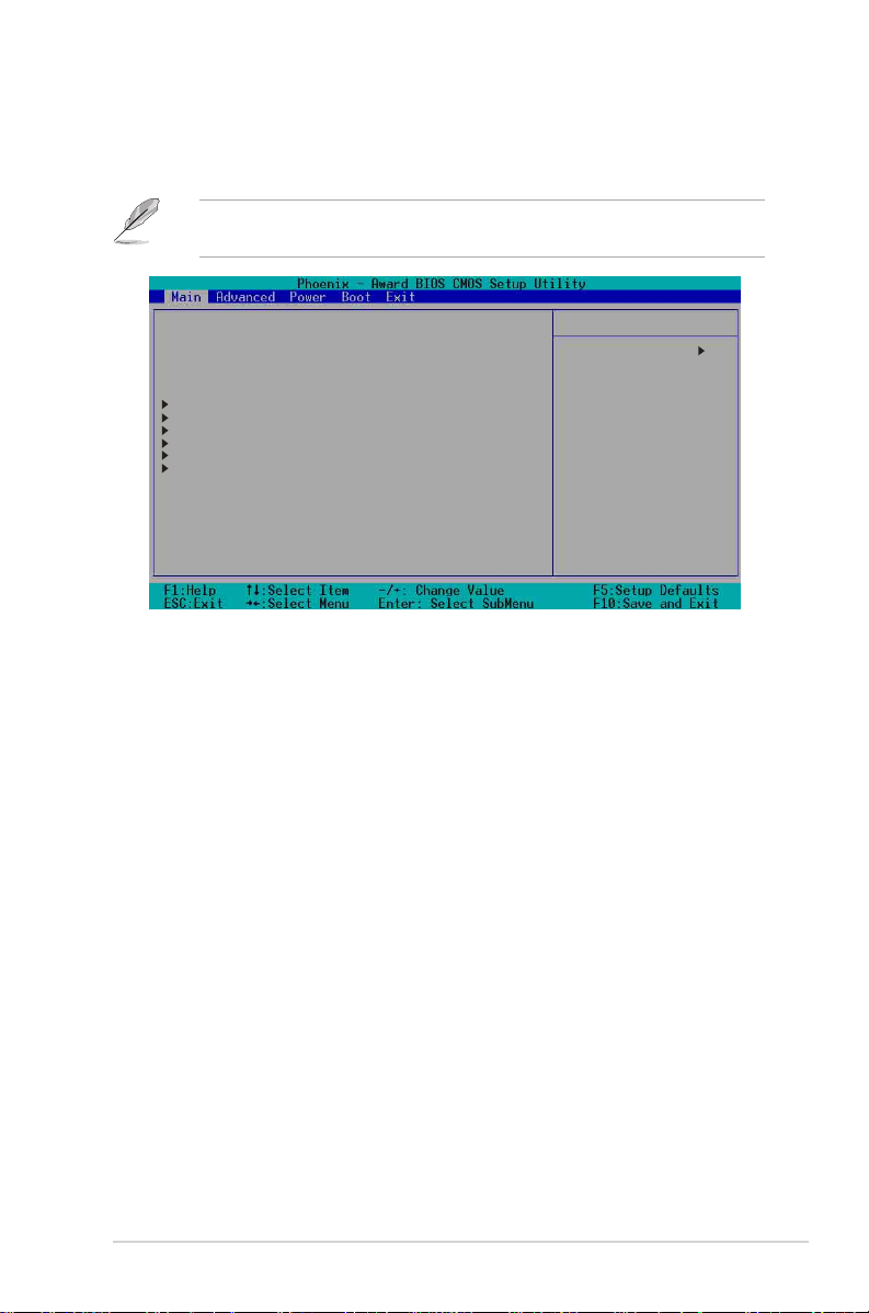
5.3 Main menu
When you enter the BIOS Setup program, the Main menu screen appears
giving you an overview of the basic system information.
Refer to section “5.2.1 BIOS menu screen” for information on the menu
screen items and how to navigate through them.
System Time 11: 10 : 30
System Date Wed, Jul 21 2004
Legacy Diskette A [1.44M, 3.5 in.]
Floppy 3 Mode Support [Disabled]
Primary IDE Master [None]
Primary IDE Slave [None]
Secondary IDE Master [None]
Secondary IDE Slave [None]
Third IDE Master [None]
Fourth IDE Master [None]
Base Memory 640K
Extended Memory 260096K
Total Memory 261120K
System Time (hh:mm:ss)System Time (hh:mm:ss)
System Time (hh:mm:ss)
System Time (hh:mm:ss)System Time (hh:mm:ss)
Select Menu
Item Specific Help
Change the internal
clock.
Sets the system to the time that you specify (usually the current time).
The format is hour:minute:second. Valid values for hour, minute, and
second are Hour: (00 to 23), Minute: (00 to 59), Second: (00 to 59). Use
the <Tab> key to move between the hour, minute, and second fields.
System Date (mm:dd:yy)System Date (mm:dd:yy)
System Date (mm:dd:yy)
System Date (mm:dd:yy)System Date (mm:dd:yy)
Sets the system to the date that you specify (usually the current date).
The format is month:day:year. Valid values for month, day, and year are
Month: (1 to 12), Day: (1 to 31), Year: (1999 to 2099). Use the <Tab>
key to move between the month, day, and year fields.
Legacy Diskette A [1.44M, 3.5 in.]Legacy Diskette A [1.44M, 3.5 in.]
Legacy Diskette A [1.44M, 3.5 in.]
Legacy Diskette A [1.44M, 3.5 in.]Legacy Diskette A [1.44M, 3.5 in.]
Sets the type of floppy drive installed. Configuration options: [Disabled]
[360K, 5.25 in.] [1.2M , 5.25 in.] [720K , 3.5 in.] [1.44M, 3.5 in.]
[2.88M, 3.5 in.]
Floppy 3 Mode Support Floppy 3 Mode Support
Floppy 3 Mode Support
Floppy 3 Mode Support Floppy 3 Mode Support
[Disabled][Disabled]
[Disabled]
[Disabled][Disabled]
Enables support for older Japanese floppy drives. The Floppy 3 Mode
feature allows reading and writing of 1.28 MB (as opposed to 1.44 MB) on
a 3.5-inch floppy disk. Configuration options: [Disabled] [Drive A]
Base/Extended/Total Memory [xxxK]Base/Extended/Total Memory [xxxK]
Base/Extended/Total Memory [xxxK]
Base/Extended/Total Memory [xxxK]Base/Extended/Total Memory [xxxK]
The base memory, extended memory, and total memory values are
auto-detected. These fields are not user-configurable.
ASUS AP1600R-E2 (AA2/AI2)ASUS AP1600R-E2 (AA2/AI2)
ASUS AP1600R-E2 (AA2/AI2)
ASUS AP1600R-E2 (AA2/AI2)ASUS AP1600R-E2 (AA2/AI2)
5-175-17
5-17
5-175-17
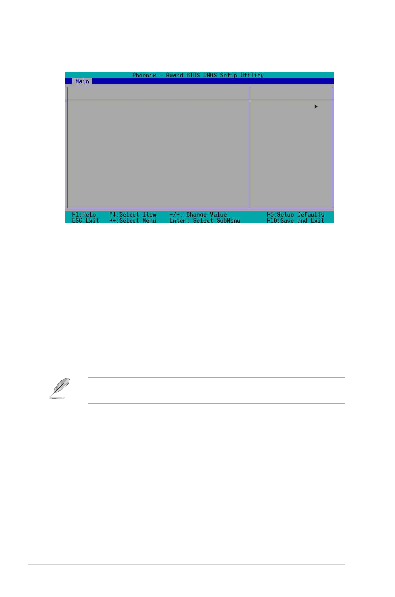
5.3.15.3.1
5.3.1
5.3.15.3.1
Primary IDE MasterPrimary IDE Master
Primary IDE Master
Primary IDE MasterPrimary IDE Master
Primary Master
Primary IDE Master [Auto]
Access Mode [Auto]
Capacity 0 MB
Cylinder 0
Head 0
Precomp 0
Landing Zone 0
Sector 0
PIO Mode [Auto]
UDMA Mode [Auto]
Transfer Mode None
S.M.A.R.T Status None
Primary IDE Master [Auto]Primary IDE Master [Auto]
Primary IDE Master [Auto]
Primary IDE Master [Auto]Primary IDE Master [Auto]
Select Menu
Item Specific Help
Selects the type of
fixed disk connected to
the system. ‘Manual’
will let you select the
number of cylinders,
heads, etc.
Note: PRECOMP=65535
means none!
Select [Auto] to automatically detect an IDE drive. If automatic detection
is successful, the setup BIOS automatically fills in the correct values for the
remaining fields on this sub-menu.
If automatic detection fails, this may be because the IDE drive is too old or
too new. If the drive was already formatted on a previous system, the BIOS
may detect incorrect parameters. In these cases, select [Manual] to
manually enter the IDE drive parameters. Refer to the section “Manually
detecting an IDE drive.”
If no drive is installed or if you are removing a drive and not replacing it,
select [None]. Configuration options: [None] [Auto] [Manual]
The IDE drive information items are grayed out when this item is set to
[Auto].
Access Mode [Auto]Access Mode [Auto]
Access Mode [Auto]
Access Mode [Auto]Access Mode [Auto]
Allows selection of the sector addressing mode. The default [Auto] allows
automatic detection of an IDE drive. Set this item to [CHS] if the
IDE MasterIDE Master
IDE Master item is set to [Manual] so you can manually enter the drive
IDE MasterIDE Master
PrimaryPrimary
Primary
PrimaryPrimary
values. Configuration options: [CHS] [LBA] [Large] [Auto]
PIO Mode [Auto]PIO Mode [Auto]
PIO Mode [Auto]
PIO Mode [Auto]PIO Mode [Auto]
Sets the PIO mode for the IDE drive. The settings Mode 0 to 4 allow
successive increase in performance. Configuration options: [Auto]
[Mode 0] [Mode 1] [Mode 2] [Mode 3] [Mode 4]
5-185-18
5-18
5-185-18
Chapter 5: BIOS setupChapter 5: BIOS setup
Chapter 5: BIOS setup
Chapter 5: BIOS setupChapter 5: BIOS setup

UDMA Mode [Auto]UDMA Mode [Auto]
UDMA Mode [Auto]
UDMA Mode [Auto]UDMA Mode [Auto]
When this item is set to [Auto], the UDMA capability allows improved
transfer speeds and data integrity for supported IDE drives. Configuration
options: [Disabled] [Auto]
Manually detecting an IDE drive
If you wish to manually enter the drive information, set the Primary IDE
Master item to [Manual], and the Access Mode item to [CHS].
Primary Master
Primary IDE Master [Manual]
Access Mode [CHS]
Capacity 0 MB
Cylinder [ 0]
Head [ 0]
Precomp [ 0]
Landing Zone [ 0]
Sector [ 0]
PIO Mode [Auto]
UDMA Mode [Auto]
Transfer Mode None
S.M.A.R.T Status None
Select Menu
Item Specific Help
Selects the type of
fixed disk connected to
the system. ‘Manual’
will let you select the
number of cylinders,
heads, etc.
Note: PRECOMP=65535
means none!
Before attempting to manually configure an IDE drive, make sure that
you have the correct configuration information supplied by the drive
manufacturer. Incorrect settings may cause the system to fail to
recognize the installed IDE drive!
To manually enter the number of cylinder, head, precomp, landing zone,
and sector per track for the drive, highlight an item, key-in the value that
you obtained from the drive documentation, then press <Enter>. Refer to
the drive documentation or the drive label for this information.
To enter a value, you may also highlight the item, then press <Enter> to
display a pop-up menu. Type in the value from the drive documentation,
then press <Enter>.
Capacity [xxxxx MB]Capacity [xxxxx MB]
Capacity [xxxxx MB]
Capacity [xxxxx MB]Capacity [xxxxx MB]
Displays the auto-detected hard disk capacity. The value is not
user-configurable.
CylinderCylinder
Cylinder
CylinderCylinder
Shows the number of the hard disk cylinders.
ASUS AP1600R-E2 (AA2/AI2)ASUS AP1600R-E2 (AA2/AI2)
ASUS AP1600R-E2 (AA2/AI2)
ASUS AP1600R-E2 (AA2/AI2)ASUS AP1600R-E2 (AA2/AI2)
5-195-19
5-19
5-195-19

HeadHead
Head
HeadHead
Shows the number of the hard disk read/write heads.
PrecompPrecomp
Precomp
PrecompPrecomp
Displays the precompressed volumes on the hard disk, if any, on the
motherboard.
Landing ZoneLanding Zone
Landing Zone
Landing ZoneLanding Zone
Displays the drive’s maximum usable capacity as calculated by the BIOS
based on the drive information you entered.
SectorSector
Sector
SectorSector
Shows the number of sectors per track.
Transfer ModeTransfer Mode
Transfer Mode
Transfer ModeTransfer Mode
Shows the data transfer mode if the IDE hard disk drive supports the
feature. Otherwise, this item is grayed out and shows the value [None].
S.M.A.R.T. StatusS.M.A.R.T. Status
S.M.A.R.T. Status
S.M.A.R.T. StatusS.M.A.R.T. Status
Shows the Smart Monitoring, Analysis, and Reporting Technology
(S.M.A.R.T.) status if the IDE hard disk drive supports the feature.
Otherwise, this item is grayed out and shows the value [None].
After entering the IDE hard disk drive information, use a disk utility, such
as FDISK, to partition and format new IDE drives. This is necessary so
that you can write or read data from the hard disk. Make sure to set the
partition of the Primary IDE hard disk drive to “Active.”
5.3.25.3.2
5.3.2
5.3.25.3.2
When configuring a drive as Primary IDE Slave, refer to section “5.3.1
Primary IDE Master” for the menu item descriptions.
5.3.35.3.3
5.3.3
5.3.35.3.3
When configuring a drive as Secondary IDE Master, refer to section “5.3.1
Primary IDE Master” for the menu item descriptions.
5.3.45.3.4
5.3.4
5.3.45.3.4
When configuring a drive as Secondary IDE Slave, refer to section “5.3.1
Primary IDE Master” for the menu item descriptions.
5-205-20
5-20
5-205-20
Primary IDE SlavePrimary IDE Slave
Primary IDE Slave
Primary IDE SlavePrimary IDE Slave
Secondary IDE MasterSecondary IDE Master
Secondary IDE Master
Secondary IDE MasterSecondary IDE Master
Secondary IDE SlaveSecondary IDE Slave
Secondary IDE Slave
Secondary IDE SlaveSecondary IDE Slave
Chapter 5: BIOS setupChapter 5: BIOS setup
Chapter 5: BIOS setup
Chapter 5: BIOS setupChapter 5: BIOS setup
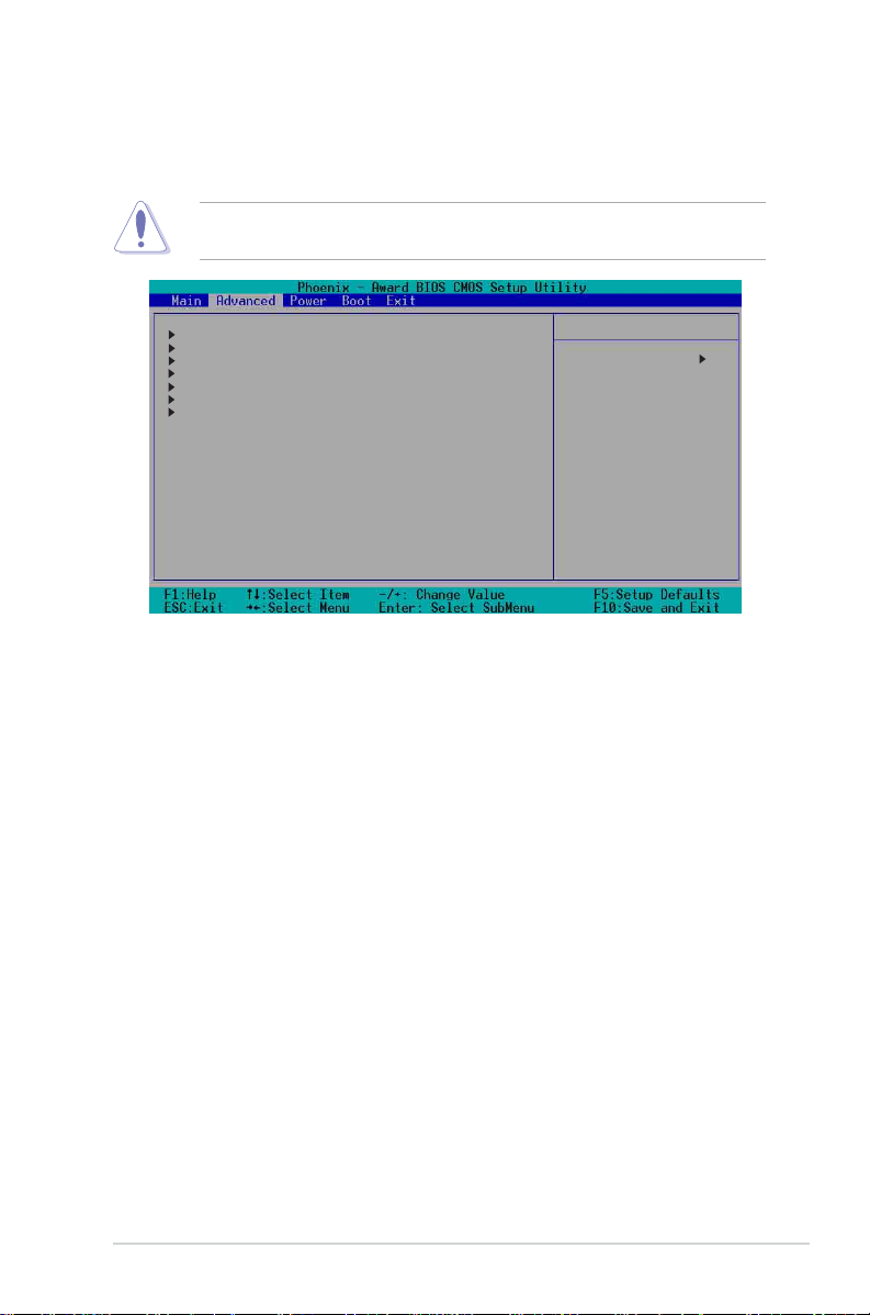
5.4 Advanced menu
The Advanced menu items allow you to change the settings for the CPU,
memory, chipset, and other system devices.
Take caution when changing the settings of the Advanced menu items.
Incorrect field values may cause the system to malfunction!
Advanced BIOS Features
CPU Configuration
Memory Configuration
Chipset
Onboard Device
PCIPnP
USB Configuration
Select Menu
Item Specific Help
Virus Protection, Boot
Sequence...
ASUS AP1600R-E2 (AA2/AI2)ASUS AP1600R-E2 (AA2/AI2)
ASUS AP1600R-E2 (AA2/AI2)
ASUS AP1600R-E2 (AA2/AI2)ASUS AP1600R-E2 (AA2/AI2)
5-215-21
5-21
5-215-21

5.4.15.4.1
5.4.1
5.4.15.4.1
Advanced BIOS FeaturesAdvanced BIOS Features
Advanced BIOS Features
Advanced BIOS FeaturesAdvanced BIOS Features
This menu shows the console redirection and agent information. Select an
item then press <Enter> to display a pop-up menu with the configuration
options.
Advanced BIOS Features Select Menu
Console Redirection [Disabled]
Baud Rate 19200
Agent Address [Auto]
Agent after boot [Disabled]
Console Redirection [Disabled]Console Redirection [Disabled]
Console Redirection [Disabled]
Console Redirection [Disabled]Console Redirection [Disabled]
Item Specific Help
Enabled - Attempt to
redirect console via COM
port.
Disabled - Attempt to
redirect console when
keyboard is absent.
Allows you to redirect the console through the serial port. when set to
[Enabled], the
Baud RateBaud Rate
Baud Rate option is activated.
Baud RateBaud Rate
Configuration options: [Disabled] [Enabled]
Baud Rate [19200]Baud Rate [19200]
Baud Rate [19200]
Baud Rate [19200]Baud Rate [19200]
Allows you to set the console redirection Baud rate. This item is
user-configurable only when the
Console Redirection Console Redirection
Console Redirection option is set to
Console Redirection Console Redirection
[Enabled]. Configuration options: [9600] [19200] [38400] [57600]
[115200]
Agent Address [Auto]Agent Address [Auto]
Agent Address [Auto]
Agent Address [Auto]Agent Address [Auto]
This option allows you to select the agent address.
Configuration options: [3F8h] [2F8h] [3E8h] [2E8h] [Auto]
Agent after boot [Disabled]Agent after boot [Disabled]
Agent after boot [Disabled]
Agent after boot [Disabled]Agent after boot [Disabled]
This option allows you to enable or disable the agent after boot-up.
Configuration options: [Disabled] [Enabled]
5-225-22
5-22
5-225-22
Chapter 5: BIOS setupChapter 5: BIOS setup
Chapter 5: BIOS setup
Chapter 5: BIOS setupChapter 5: BIOS setup

5.4.25.4.2
5.4.2
5.4.25.4.2
CPU ConfigurationCPU Configuration
CPU Configuration
CPU ConfigurationCPU Configuration
This menu shows the CPU configuration settings. Select an item then press
<Enter> to display a pop-up menu with the configuration options.
CPU Configuration Select Menu
CPU L1 & L2 Cache [Enabled]
Hyper-Threading Technology [Enabled]
CPU L1 & L2 Cache [Enabled]CPU L1 & L2 Cache [Enabled]
CPU L1 & L2 Cache [Enabled]
CPU L1 & L2 Cache [Enabled]CPU L1 & L2 Cache [Enabled]
Item Specific Help
Disable/Enable CPU L1
L2 cache.
Allows you to enable or disable the CPU L1 and L2 cache.
Configuration options: [Disabled] [Enabled]
Hyper-Threading Technology [Enabled]Hyper-Threading Technology [Enabled]
Hyper-Threading Technology [Enabled]
Hyper-Threading Technology [Enabled]Hyper-Threading Technology [Enabled]
Allows you to enable or disable the Hyper-Threading Technology.
Configuration options: [Disabled] [Enabled]
ASUS AP1600R-E2 (AA2/AI2)ASUS AP1600R-E2 (AA2/AI2)
ASUS AP1600R-E2 (AA2/AI2)
ASUS AP1600R-E2 (AA2/AI2)ASUS AP1600R-E2 (AA2/AI2)
5-235-23
5-23
5-235-23

5.4.35.4.3
5.4.3
5.4.35.4.3
Memory ConfigurationMemory Configuration
Memory Configuration
Memory ConfigurationMemory Configuration
This menu shows the memory configuration settings. Select an item then
press <Enter> to display a pop-up menu with the configuration options.
Memory Configuration Select Menu
DRAM Frequency [Auto]
Memory Timing Selectable [By SPD]
Cache Latency Time 3
Active to Precharge Delay 8
DRAM RAS# to CAS# Delay 4
DRAM RAS# Precharge 4
Memory Parity Check Disabled
DRAM Frequency [Auto]DRAM Frequency [Auto]
DRAM Frequency [Auto]
DRAM Frequency [Auto]DRAM Frequency [Auto]
Item Specific Help
Set DRAM Frequency.
This item sets the DRAM operating frequency.
Configuration options: [DDR266] [DDR320] [DDR400] [Auto]
Memory Timing Selectable [By SPD]Memory Timing Selectable [By SPD]
Memory Timing Selectable [By SPD]
Memory Timing Selectable [By SPD]Memory Timing Selectable [By SPD]
The DRAM clock are set according to the DRAM SPD (Serial Presence
Detect). Select [By SPD] for automatic DRAM clock detection. Select
[Manual] to allow setting the succeeding memory items to optimal timings.
Configuration options: [Manual] [By SPD]
The items CAS Latency Time, Active to Precharge Delay, DRAM RAS# to
CAS# Delay, and DRAM RAS# Precharge are configurable only when the
Memory Timing Selectable item is set to [Manual].
CAS Latency Time [2.5]CAS Latency Time [2.5]
CAS Latency Time [2.5]
CAS Latency Time [2.5]CAS Latency Time [2.5]
This item sets the latency (in clocks) between the DRAM read command
and the time the data actually becomes available.
Configuration options: [2] [2.5] [3]
Active to Precharge Delay [7]Active to Precharge Delay [7]
Active to Precharge Delay [7]
Active to Precharge Delay [7]Active to Precharge Delay [7]
This item controls the number of DRAM clocks used for DRAM parameters.
Configuration options: [8] [7] [6] [5]
DRAM RAS# to CAS# Delay [3]DRAM RAS# to CAS# Delay [3]
DRAM RAS# to CAS# Delay [3]
DRAM RAS# to CAS# Delay [3]DRAM RAS# to CAS# Delay [3]
Controls the latency between the DRAM active command and the read/
write command. Configuration options: [4] [3] [2]
5-245-24
5-24
5-245-24
Chapter 5: BIOS setupChapter 5: BIOS setup
Chapter 5: BIOS setup
Chapter 5: BIOS setupChapter 5: BIOS setup

DRAM RAS# Precharge [3]DRAM RAS# Precharge [3]
DRAM RAS# Precharge [3]
DRAM RAS# Precharge [3]DRAM RAS# Precharge [3]
This item controls the idle clocks after issuing a precharge command to the
DDR SDRAM. Configuration options: [4] [3] [2]
Memory Parity Check [Enabled]Memory Parity Check [Enabled]
Memory Parity Check [Enabled]
Memory Parity Check [Enabled]Memory Parity Check [Enabled]
Allows memory parity checking option. This item is not user-configurable
and set to [Enabled] by default.
5.4.45.4.4
5.4.4
5.4.45.4.4
ChipsetChipset
Chipset
ChipsetChipset
This menu shows the chipset configuration settings. Select an item then
press <Enter> to display a sub-menu with additional items, or show a popup menu with the configuration options.
Chipset Select Menu
System BIOS Cacheable [Enabled]
Video BIOS Cacheable [Disabled]
Init Display First [PCI VGA Card]
Auto Detect PCI Clk [Enabled]
System BIOS Cacheable [Enabled]System BIOS Cacheable [Enabled]
System BIOS Cacheable [Enabled]
System BIOS Cacheable [Enabled]System BIOS Cacheable [Enabled]
Item Specific Help
Press <Enter> to enable
or disable BIOS
cacheable.
Allows you to enable or disable the cache function of the system BIOS.
Configuration options: [Disabled] [Enabled]
Video BIOS Cacheable [Disabled]Video BIOS Cacheable [Disabled]
Video BIOS Cacheable [Disabled]
Video BIOS Cacheable [Disabled]Video BIOS Cacheable [Disabled]
Allows you to enable or disable the cache function of the video BIOS.
Setting to [Enabled] improves the display speed by caching the display
data. Configuration options: [Disabled] [Enabled]
Init Display First [PCI VGA Card]Init Display First [PCI VGA Card]
Init Display First [PCI VGA Card]
Init Display First [PCI VGA Card]Init Display First [PCI VGA Card]
Allows you to select the graphics controller to use as primary boot device.
Configuration options: [PCI VGA Card] [Onboard VGA]
Auto Detect PCI Clk [Enabled]Auto Detect PCI Clk [Enabled]
Auto Detect PCI Clk [Enabled]
Auto Detect PCI Clk [Enabled]Auto Detect PCI Clk [Enabled]
Allows you to select the maximum PCI bus speed to be programmed.
Configuration options: [Enabled] [Disabled]
ASUS AP1600R-E2 (AA2/AI2)ASUS AP1600R-E2 (AA2/AI2)
ASUS AP1600R-E2 (AA2/AI2)
ASUS AP1600R-E2 (AA2/AI2)ASUS AP1600R-E2 (AA2/AI2)
5-255-25
5-25
5-255-25

5.4.55.4.5
5.4.5
5.4.55.4.5
Onboard DeviceOnboard Device
Onboard Device
Onboard DeviceOnboard Device
This menu shows the onboard device configuration settings. Select an item
then press <Enter> to display a sub-menu with additional items, or show a
pop-up menu with the configuration options.
Onboard Device
H/W Jumper of CSA LAN Enabled
Onboard CSA LAN Boot ROM [Disabled]
H/W Jumper of ONB LAN Enabled
Onboard LAN Boot ROM [Disabled]
Super I/O Device
SATA Configuration
H/W Jumper of CSA LAN [Enabled]H/W Jumper of CSA LAN [Enabled]
H/W Jumper of CSA LAN [Enabled]
H/W Jumper of CSA LAN [Enabled]H/W Jumper of CSA LAN [Enabled]
Select Menu
Item Specific Help
Enable/Disable Onboard
CSA LAN device boot ROM
support.
This option tells whether the CSA LAN jumper labeled LAN_EN1 on the
motherboard is enabled or disabled. See section “2.6 Jumpers” for details.
Onboard CSA LAN Boot ROM [Disabled]Onboard CSA LAN Boot ROM [Disabled]
Onboard CSA LAN Boot ROM [Disabled]
Onboard CSA LAN Boot ROM [Disabled]Onboard CSA LAN Boot ROM [Disabled]
Allows you to enable or disable the onboard CSA LAN boot ROM.
Configuration options: [Disabled] [Enabled]
H/W Jumper of ONB LAN [Enabled]H/W Jumper of ONB LAN [Enabled]
H/W Jumper of ONB LAN [Enabled]
H/W Jumper of ONB LAN [Enabled]H/W Jumper of ONB LAN [Enabled]
This option tells whether the onboard LAN jumper labeled LAN_EN2 on the
motherboard is enabled or disabled. See section “2.6 Jumpers” for details.
Onboard LAN Boot ROM [Disabled]Onboard LAN Boot ROM [Disabled]
Onboard LAN Boot ROM [Disabled]
Onboard LAN Boot ROM [Disabled]Onboard LAN Boot ROM [Disabled]
Allows you to enable or disable the onboard LAN boot ROM.
Configuration options: [Disabled] [Enabled]
5-265-26
5-26
5-265-26
Chapter 5: BIOS setupChapter 5: BIOS setup
Chapter 5: BIOS setup
Chapter 5: BIOS setupChapter 5: BIOS setup

Super I/O DeviceSuper I/O Device
Super I/O Device
Super I/O DeviceSuper I/O Device
Super I/O Device
Serial Port1 Address [3F8/IRQ4]
Serial Port2 Address [2F8/IRQ3]
Onboard Parallel Port [378/IRQ7]
Parallel Port Mode [SPP]
EPP Mode Select EPP1.7
ECP Mode Use DMA 3
Serial Port 1 [3F8/IRQ4]Serial Port 1 [3F8/IRQ4]
Serial Port 1 [3F8/IRQ4]
Serial Port 1 [3F8/IRQ4]Serial Port 1 [3F8/IRQ4]
Serial Port 2 [2F8/IRQ3]Serial Port 2 [2F8/IRQ3]
Serial Port 2 [2F8/IRQ3]
Serial Port 2 [2F8/IRQ3]Serial Port 2 [2F8/IRQ3]
Select Menu
Item Specific Help
Set Base I/O address
for serial port 1.
Allow you to select the serial port base addresses.
Configuration options: [Disabled] [3F8/IRQ4] [2F8/IRQ3] [3E8/IRQ4]
[2E8/IRQ3] [Auto]
Onboard Parallel Port [378/IRQ7]Onboard Parallel Port [378/IRQ7]
Onboard Parallel Port [378/IRQ7]
Onboard Parallel Port [378/IRQ7]Onboard Parallel Port [378/IRQ7]
Allows you to select the parellel port base address.
Configuration options: [Disabled] [378/IRQ7] [278/IRQ5] [3BC/IRQ7]
Parallel Port Mode [SPP]Parallel Port Mode [SPP]
Parallel Port Mode [SPP]
Parallel Port Mode [SPP]Parallel Port Mode [SPP]
Allows you to select the parallel port mode.
Configuration options: [SPP] [EPP] [ECP] [ECP+EPP] [Normal]
EPP Mode Select [EPP1.7]EPP Mode Select [EPP1.7]
EPP Mode Select [EPP1.7]
EPP Mode Select [EPP1.7]EPP Mode Select [EPP1.7]
Allows you to select the EPP mode. This item becomes configurable only if
Parallel Port ModeParallel Port Mode
the
Parallel Port Mode is set to [EPP] or [ECP+EPP].|
Parallel Port ModeParallel Port Mode
Configuration options: [EPP 1.9] [EPP 1.7]
ECP Mode Use DMA [3]ECP Mode Use DMA [3]
ECP Mode Use DMA [3]
ECP Mode Use DMA [3]ECP Mode Use DMA [3]
Allows you to select the ECP mode. This item becomes configurable only if
Parallel Port ModeParallel Port Mode
the
Parallel Port Mode is set to [ECP] or [ECP+EPP].
Parallel Port ModeParallel Port Mode
Configuration options: [1] [3]
ASUS AP1600R-E2 (AA2/AI2)ASUS AP1600R-E2 (AA2/AI2)
ASUS AP1600R-E2 (AA2/AI2)
ASUS AP1600R-E2 (AA2/AI2)ASUS AP1600R-E2 (AA2/AI2)
5-275-27
5-27
5-275-27
SATA ConfigurationSATA Configuration
SATA Configuration
SATA ConfigurationSATA Configuration
SATA Configuration
*** On-Chip Serial ATA Setting ***
On-Chip Serial ATA [Auto]
SATA Mode IDE
Serial ATA Port0 Mode SATA0 master
Serial ATA Port1 Mode SATA1 master
***On-Chip Serial ATA Setting******On-Chip Serial ATA Setting***
***On-Chip Serial ATA Setting***
***On-Chip Serial ATA Setting******On-Chip Serial ATA Setting***
Select Menu
Item Specific Help
[Disabled]: Disable
SATA Controller.
[Auto]: Auto-arrange
the BIOS.
[Combined Mode]: PATA
and SATA are combined.
Max. of 2 IDE drives on
each channel.
[Enhanced Mode]: Enable
both SATA and PATA.
Max. of 6 IDE drives
are supported.
[SATA Only]: SATA is
opeating in legacy
mode.
The SATA Mode and Serial ATA Port0 Mode items are configurable
only when the On-Chip Serial ATA item is set to [ Combined Mode]
[Enhanced Mode] or [SATA Only].
On-chip Serial ATA [Auto]On-chip Serial ATA [Auto]
On-chip Serial ATA [Auto]
On-chip Serial ATA [Auto]On-chip Serial ATA [Auto]
This item allows you to configure your serial ATA devices, if present.
Configuration options: [Disabled] [Auto] [Combined Mode]
[Enhanced Mode] [SATA Only]
a. Setting to [
AutoAuto
Auto] allows BIOS to automatically configure the SATA
AutoAuto
devices.
b. Setting to [
serial ATA devices at the same time. You may install
devices on any of the parallel ATA channelsdevices on any of the parallel ATA channels
devices on any of the parallel ATA channels, and
devices on any of the parallel ATA channelsdevices on any of the parallel ATA channels
device on each serial ATA channeldevice on each serial ATA channel
device on each serial ATA channel for a maximum of
device on each serial ATA channeldevice on each serial ATA channel
Combined ModeCombined Mode
Combined Mode] allows you to install parallel ATA and
Combined ModeCombined Mode
two IDEtwo IDE
two IDE
two IDEtwo IDE
one IDEone IDE
one IDE
one IDEone IDE
fourfour
four
fourfour
devices. Use ths option when you installed a legacy operating system
like MS-DOS, Windows ME/98/NT4.0.
c. Setting to [
serial ATA devices at the same time, with a maximum of
Enhanced ModeEnhanced Mode
Enhanced Mode] allows you to install parallel ATA and
Enhanced ModeEnhanced Mode
six six
six IDE
six six
devices on each channel. Use this option when you installed a native
operating system like Windows 2000/XP.
d. Setting to [
SATA OnlySATA Only
SATA Only] allows you to install IDE devices on the
SATA OnlySATA Only
Serial ATA channels only.
e. Setting to [
DisabledDisabled
Disabled] disables the onboard SATA controller. The
DisabledDisabled
RAID feature is also disabled.
5-285-28
5-28
5-285-28
Chapter 5: BIOS setupChapter 5: BIOS setup
Chapter 5: BIOS setup
Chapter 5: BIOS setupChapter 5: BIOS setup

SATA Mode [IDE]SATA Mode [IDE]
SATA Mode [IDE]
SATA Mode [IDE]SATA Mode [IDE]
When set to [RAID], this item allows configuration of the installed IDE
devices into a disk array. Configuration options: [IDE] [RAID]
Serial ATA Port0 Mode [SATA0 master]Serial ATA Port0 Mode [SATA0 master]
Serial ATA Port0 Mode [SATA0 master]
Serial ATA Port0 Mode [SATA0 master]Serial ATA Port0 Mode [SATA0 master]
Serial ATA Port1 Mode [SATA1 master]Serial ATA Port1 Mode [SATA1 master]
Serial ATA Port1 Mode [SATA1 master]
Serial ATA Port1 Mode [SATA1 master]Serial ATA Port1 Mode [SATA1 master]
Allow you to set the SATA Port0 and Serial ATA Port1 modes. The options
for these items vary depending on the setting of the
ATA ATA
ATA item. Configuration options: [Primary Master] [Primary Slave]
ATA ATA
[Secondary Master] [Secondary Slave] [SATA0 master] SATA1 master]
On-Chip SerialOn-Chip Serial
On-Chip Serial
On-Chip SerialOn-Chip Serial
ASUS AP1600R-E2 (AA2/AI2)ASUS AP1600R-E2 (AA2/AI2)
ASUS AP1600R-E2 (AA2/AI2)
ASUS AP1600R-E2 (AA2/AI2)ASUS AP1600R-E2 (AA2/AI2)
5-295-29
5-29
5-295-29
5.4.65.4.6
5.4.6
5.4.65.4.6
PCIPnPPCIPnP
PCIPnP
PCIPnPPCIPnP
This menu shows the PCIPnP configuration settings. Select an item then
press <Enter> to display a pop-up menu with the configuration options.
PCIPnP Select Menu
Reset Configuration Data [Disabled]
Resources Controlled By [Auto]
IRQ Resources
PCI/VGA Pallete Snoop [Disabled]
INT Pin 1 Assignment [Auto]
INT Pin 2 Assignment [Auto]
INT Pin 3 Assignment [Auto]
INT Pin 4 Assignment [Auto]
INT Pin 5 Assignment [Auto]
INT Pin 6 Assignment [Auto]
INT Pin 7 Assignment [Auto]
INT Pin 8 Assignment [Auto]
Reset Configuration Data [Disabled]Reset Configuration Data [Disabled]
Reset Configuration Data [Disabled]
Reset Configuration Data [Disabled]Reset Configuration Data [Disabled]
Item Specific Help
Default is Disabled.
Select Enabled to reset
Extended System
Configuration Data
(ESCD) when you exit
Setup, if you installed
a new add-on card and
the system
reconfiguration has
caused a serious
conflict that the OS
cannot boot.
Allows you to enable or disabled resetting of the Extended System
Configuration Data (ESCD) when you exit the Setup. The ESCD includes
information on non-PnP devices. Set this item to [Enabled] if you installed
an expansion card that conflicts with other devices and cause system boot
failure. Configuration options: [Disabled] [Enabled]
Resources Controlled By [Auto]Resources Controlled By [Auto]
Resources Controlled By [Auto]
Resources Controlled By [Auto]Resources Controlled By [Auto]
When set to [Auto(ESCD)], allows BIOS to automatically configure of all
boot and Plug and Play devices. When set to [Manual], you can assign the
available IRQ Resources to the PCI devices.
Configuration options: [Auto] [Manual]
When the item
IRQ Resources is grayed out and not user-configurable. Refer to the
section “IRQ Resources” for information on how to enable this item.
PCI/VGA Pallete Snoop [Disabled]PCI/VGA Pallete Snoop [Disabled]
PCI/VGA Pallete Snoop [Disabled]
PCI/VGA Pallete Snoop [Disabled]PCI/VGA Pallete Snoop [Disabled]
Resources Controlled ByResources Controlled By
Resources Controlled By is set to [Auto], the item
Resources Controlled ByResources Controlled By
Some non-standard VGA cards, like graphics accelerators or MPEG video
cards, may not show colors properly. Setting this field to [Enabled] corrects
this problem. If you are using a standard VGA card, leave this field to the
default setting [Disabled]. Configuration options: [Disabled] [Enabled]
INT Pin 1~8 Assignment [Auto]INT Pin 1~8 Assignment [Auto]
INT Pin 1~8 Assignment [Auto]
INT Pin 1~8 Assignment [Auto]INT Pin 1~8 Assignment [Auto]
Allows you to select the appropriate interrupt to the specific devices to
avoid conflict. Configuration options: [Auto] [3] [4] [5] [7] [9] [10] [11]
[12] [14] [15]
5-305-30
5-30
5-305-30
Chapter 5: BIOS setupChapter 5: BIOS setup
Chapter 5: BIOS setup
Chapter 5: BIOS setupChapter 5: BIOS setup
IRQ ResourcesIRQ Resources
IRQ Resources
IRQ ResourcesIRQ Resources
Set the item
the item
Resources Controlled ByResources Controlled By
Resources Controlled By is set to [Manual] to enable
Resources Controlled ByResources Controlled By
IRQ ResourcesIRQ Resources
IRQ Resources and assign the interrupts depending on the
IRQ ResourcesIRQ Resources
type of installed PCI device.
PCIPnP Select Menu
Reset Configuration Data [Disabled]
Resources Controlled By [Manual]
IRQ Resources
PCI/VGA Pallete Snoop [Disabled]
INT Pin 1 Assignment [Auto]
INT Pin 2 Assignment [Auto]
INT Pin 3 Assignment [Auto]
INT Pin 4 Assignment [Auto]
IRQ Resources
IRQ-3 assigned to [PCI Device]
IRQ-4 assigned to [PCI Device]
IRQ-5 assigned to [PCI Device]
IRQ-7 assigned to [PCI Device]
IRQ-9 assigned to [PCI Device]
IRQ-10 assigned to [PCI Device]
IRQ-11 assigned to [PCI Device]
IRQ-12 assigned to [PCI Device]
IRQ-14 assigned to [PCI Device]
IRQ-15 assigned to [PCI Device]
Item Specific Help
BIOS can automatically
configure all the boot
and Plug and Play
compatible devices. If
you choose auto, you
cannot select IRQ DMA
and memory base address
fields, since BIOS
Select Menu
Item Specific Help
Legacy ISA for devices
compliant with the
original PC AT bus
specification, PCI/ISA
PnP for devices
compliant with the Plug
and Play standard
whether designed for PCI
or ISA bus architecture.
IRQ-xx assigned to [PCI device]IRQ-xx assigned to [PCI device]
IRQ-xx assigned to [PCI device]
IRQ-xx assigned to [PCI device]IRQ-xx assigned to [PCI device]
The IRQ Resources sub-menu is activated when the Resources Controlled by
parameter is set to [Manual]. Select [PCI Device] to assign an IRQ address
to a Plug and Play device. Setting to [Reserved] reserves the IRQ address.
Configuration options: [PCI Device] [Reserved]
ASUS AP1600R-E2 (AA2/AI2)ASUS AP1600R-E2 (AA2/AI2)
ASUS AP1600R-E2 (AA2/AI2)
ASUS AP1600R-E2 (AA2/AI2)ASUS AP1600R-E2 (AA2/AI2)
5-315-31
5-31
5-315-31

5.4.75.4.7
5.4.7
5.4.75.4.7
USB ConfigurationUSB Configuration
USB Configuration
USB ConfigurationUSB Configuration
This menu shows the USB configuration settings. Select an item then press
<Enter> to display a pop-up menu with the configuration options.
USB Configuration
USB Controller [Enabled]
USB 2.0 Support [Enabled]
USB Legacy Mode Support [Enabled]
USB Controller [Enabled]USB Controller [Enabled]
USB Controller [Enabled]
USB Controller [Enabled]USB Controller [Enabled]
Select Menu
Item Specific Help
Configures the USB
controller.
Allows you enable or disable the USB controller.
Configuration options: [Enabled] [Disabled]
USB 2.0 Support [Enabled]USB 2.0 Support [Enabled]
USB 2.0 Support [Enabled]
USB 2.0 Support [Enabled]USB 2.0 Support [Enabled]
Allows you to enable or disable the EHCI controller. Setting this item to
[Enabled] allows the built-in high speed USB support in the BIOS to turn on
automatically when you install high speed USB devices.
Configuration options: [Enabled] [Disabled]
USB Legacy Mode Support [Enabled]USB Legacy Mode Support [Enabled]
USB Legacy Mode Support [Enabled]
USB Legacy Mode Support [Enabled]USB Legacy Mode Support [Enabled]
Allows you enable or disable support for the legacy USB devices.
Configuration options: [Disabled] [Enabled]
5-325-32
5-32
5-325-32
Chapter 5: BIOS setupChapter 5: BIOS setup
Chapter 5: BIOS setup
Chapter 5: BIOS setupChapter 5: BIOS setup
 Loading...