

Page 1
AP140R-E1
Intel® Pentium® 4 1U Rackmount Server
800/533MHz Front Side Bus
User Guide
Page 2

E1656
Revised edition V2
August 2004
Copyright © 2004 ASUSTeK COMPUTER INC. All Rights Reserved.
No part of this manual, including the products and software described in it, may be
reproduced, transmitted, transcribed, stored in a retrieval system, or translated into any
language in any form or by any means, except documentation kept by the purchaser for
backup purposes, without the express written permission of ASUSTeK COMPUTER INC.
(“ASUS”).
ASUS provides this manual “as is” without warranty of any kind, either express or implied,
including but not limited to the implied warranties or conditions of merchantability or fitness
for a particular purpose. In no event shall ASUS, its directors, officers, employees, or agents
be liable for any indirect, special, incidental, or consequential damages (including damages
for loss of profits, loss of business, loss of use or data, interruption of business and the like),
even if ASUS has been advised of the possibility of such damages arising from any defect or
error in this manual or product.
Specifications and information contained in this manual ae furnished for informational use
only, and are subject to change at any time without notice, and should not be construed as a
commitment by ASUS. ASUS assumes no responsibility or liability for any errors or
inaccuracies that may appear in this manual, including the products and software described
in it.
Product warranty or service will not be extended if: (1) the product is repaired, modified or
altered, unless such repair, modification of alteration is authorized in writing by ASUS; or (2)
the serial number of the product is defaced or missing.
Products and corporate names appearing in this manual may or may not be registered
trademarks or copyrights of their respective companies, and are used only for identification or
explanation and to the owners’ benefit, without intent to infringe.
ii
Page 3

Contents
Notices ...........................................................................................vi
Safety information ......................................................................... vii
About this guide............................................................................ viii
Chapter 1: Product introduction ......................................... 1-1
1.1 System package contents .................................................. 1-2
1.2 System specifications......................................................... 1-3
1.3 Front panel features ........................................................... 1-4
1.4 Rear panel features............................................................ 1-5
1.5 Internal features ................................................................. 1-6
1.6 LED information.................................................................. 1-7
1.6.1 Front panel LEDs ................................................... 1-7
1.6.2 Rear panel LEDs ................................................... 1-7
Chapter 2: Hardware setup.................................................. 2-1
2.1 Chassis cover..................................................................... 2-2
2.1.1 Removing the cover ............................................... 2-2
2.1.2 Installing the cover ................................................. 2-3
2.2 Central Processing Unit (CPU)........................................... 2-4
2.2.1 Removing the CPU heatsink.................................. 2-4
2.2.2 Installing a CPU ..................................................... 2-4
2.2.3 Installing the CPU heatsink.................................... 2-6
2.3 System memory ................................................................. 2-7
2.3.1 Memory configurations .......................................... 2-7
2.3.2 Installing a DIMM ................................................... 2-9
2.3.3 Removing a DIMM ................................................. 2-9
2.4 Hard disk drives................................................................ 2-10
2.4.1 Installing an IDE hard disk drive .......................... 2-10
2.4.2 Installing a Serial ATA hard disk drive .................. 2-12
2.4.3 Installing a hot-swap Serial ATA HDD .................. 2-13
2.5 Expansion cards............................................................... 2-15
2.5.1 Installing a PCI card............................................. 2-15
2.5.2 Configuring an expansion card ............................ 2-17
2.6 Cable connections............................................................ 2-18
iii
Page 4

Contents
2.7 Removable components................................................... 2-20
2.7.1 System fans ......................................................... 2-20
2.7.2 Device fan ............................................................ 2-20
2.7.3 Rear fan ............................................................... 2-20
2.7.4 Power supply module .......................................... 2-21
2.7.5 Optical drive ......................................................... 2-22
2.7.6 Motherboard ........................................................ 2-24
Chapter 3: Installation options ............................................ 3-1
3.1 Rackmount rail kit items ..................................................... 3-2
3.2 Rack rails assembly ........................................................... 3-2
3.3 Attaching the rails to the rack ............................................. 3-3
3.4 Rackmounting the server ................................................... 3-4
Chapter 4: Motherboad information .................................... 4-1
4.1 Motherboard layout ............................................................ 4-2
4.2 Jumpers.............................................................................. 4-4
4.3 Connectors ......................................................................... 4-8
Chapter 5: BIOS Setup......................................................... 5-1
5.1 Managing and updating your BIOS .................................... 5-2
5.1.1 Creating a bootable floppy disk ............................. 5-2
5.1.2 Updating the BIOS ................................................. 5-3
5.2 BIOS Setup program .......................................................... 5-4
5.2.1 BIOS menu screen ................................................ 5-5
5.2.2 Menu bar................................................................ 5-5
5.2.3 Navigation keys ..................................................... 5-6
5.2.4 General help .......................................................... 5-6
5.2.5 Sub-menu .............................................................. 5-6
5.2.6 Scroll bar................................................................ 5-6
5.2.7 Pop-up window ...................................................... 5-6
5.3 Main menu.......................................................................... 5-7
5.3.1 Primary IDE Master ............................................... 5-8
5.3.2 Primary IDE Slave ................................................5-11
5.3.3 Secondary IDE Master..........................................5-11
5.3.4 Secondary IDE Slave............................................5-11
iv
Page 5

5.4 Advanced menu ............................................................... 5-12
5.4.1 Advanced BIOS Features .................................... 5-12
5.4.2 CPU Configuration ............................................... 5-13
5.4.3 Memory Configuration ......................................... 5-14
5.4.4 Chipset................................................................. 5-16
5.4.5 Onboard Device ................................................... 5-18
5.4.6 PCIPnP ................................................................ 5-22
5.4.7 USB Configuration ............................................... 5-24
5.5 Power menu ..................................................................... 5-25
5.5.1 APM Configuration............................................... 5-26
5.5.2 Hardware Monitor ................................................ 5-29
5.6 Boot menu ........................................................................ 5-30
5.6.1 Boot Device Priority ............................................. 5-30
5.6.2 Hard Disk Boot Priority ........................................ 5-31
5.6.3 Removable Device Priority .................................. 5-31
5.6.4 Boot Settings Configuration ................................. 5-32
5.6.5 Security ................................................................ 5-33
5.7 Exit menu ......................................................................... 5-35
Appendix: References ..........................................................A-1
A.1 Power supply...................................................................... A-2
A.1.1 General description................................................ A-2
A.1.2 Specifications......................................................... A-3
A.2 Qualified Vendors List (QVL).............................................. A-4
A.3 Troubleshooting..................................................................A-5
v
Page 6

Notices
Federal Communications Commission Statement
This device complies with Part 15 of the FCC Rules. Operation is subject
to the following two conditions:
• This device may not cause harmful interference, and
• This device must accept any interference received including interference
that may cause undesired operation.
This equipment has been tested and found to comply with the limits for a
Class B digital device, pursuant to Part 15 of the FCC Rules. These limits
are designed to provide reasonable protection against harmful interference
in a residential installation. This equipment generates, uses and can
radiate radio frequency energy and, if not installed and used in
accordance with manufacturer’s instructions, may cause harmful
interference to radio communications. However, there is no guarantee that
interference will not occur in a particular installation. If this equipment does
cause harmful interference to radio or television reception, which can be
determined by turning the equipment off and on, the user is encouraged to
try to correct the interference by one or more of the following measures:
• Reorient or relocate the receiving antenna.
• Increase the separation between the equipment and receiver.
• Connect the equipment to an outlet on a circuit different from that to
which the receiver is connected.
• Consult the dealer or an experienced radio/TV technician for help.
WARNING! The use of shielded cables for connection of the monitor
to the graphics card is required to assure compliance with FCC
regulations. Changes or modifications to this unit not expressly
approved by the party responsible for compliance could void the user’s
authority to operate this equipment.
Canadian Department of Communications Statement
This digital apparatus does not exceed the Class B limits for radio noise
emissions from digital apparatus set out in the Radio Interference
Regulations of the Canadian Department of Communications.
This class B digital apparatus complies with Canadian ICES-003.
vi
Page 7

Safety information
Electrical Safety
• Before installing or removing signal cables, ensure that the power cables for
the system unit and all attached devices are unplugged.
• To prevent electrical shock hazard, disconnect the power cable from the
electrical outlet before relocating the system.
• When adding or removing any additional devices to or from the system, ensure
that the power cables for the devices are unplugged before the signal cables
are connected. If possible, disconnect all power cables from the existing
system before you add a device.
• If the power supply is broken, do not try to fix it by yourself. Contact a qualified
service technician or your dealer.
Operation Safety
• Any mechanical operation on this server must be conducted by certified or
experienced engineers.
• Before operating the server, carefully read all the manuals included with the
server package.
• Before using the server, make sure all cables are correctly connected and the
power cables are not damaged. If any damage is detected, contact your dealer
as soon as possible.
• To avoid short circuits, keep paper clips, screws, and staples away from
connectors, slots, sockets and circuitry.
• Avoid dust, humidity, and temperature extremes. Place the server on a stable
surface.
This product is equipped with a three-wire power cable and plug for the
user’s safety. Use the power cable with a properly grounded electrical
outlet to avoid electrical shock.
Lithium-Ion Battery Warning
CAUTION! Danger of explosion if battery is incorrectly replaced. Replace
only with the same or equivalent type recommended by the manufacturer.
Dispose of used batteries according to the manufacturer’s instructions.
CD-ROM Drive Safety Warning
CLASS 1 LASER PRODUCT
vii
Page 8

About this guide
Audience
This user guide is intended for system integrators, and experienced users
with at least basic knowledge of configuring a server.
Contents
This guide contains the following parts:
1. Chapter 1: Product Introduction
This chapter describes the general features of the barebone server. It
includes sections on front panel and rear panel specifications.
2. Chapter 2: Hardware setup
This chapter lists the hardware setup procedures that you have to
perform when installing or removing system components.
3. Chapter 3: Configuration options
This chapter describes the optional installation procedures for the
barebone server.
4. Chapter 4: Motherboard information
This chapter includes the motherboard layout, and brief descriptions of
the jumpers and internal connectors.
5. Chapter 5: BIOS setup
This chapter tells how to change the system settings through the BIOS
Setup menus.
6. Appendix: References
This appendix includes additional information that you may refer to
when configuring your barebone server.
Conventions
To make sure that you perform certain tasks properly, take note of the
following symbols used throughout this manual.
viii
WARNING: Information to prevent injury to yourself when trying to
complete a task.
CAUTION: Information to prevent damage to the components when
trying to complete a task.
IMPORTANT: Information that you MUST follow to complete a task.
NOTE: Tips and information to aid in completing a task.
Page 9

Chapter 1
This chapter describes the general features
of the barebone server. It includes sections
on front panel and rear panel specifications.
ASUS AP140R-E1 1U barebone server
Product introduction
1-1
Page 10
1.1 System package contents
The items in the ASUS AP140R-E1 product package vary depending on
the model your purchased. Check your package for the standard items
listed in the following table.
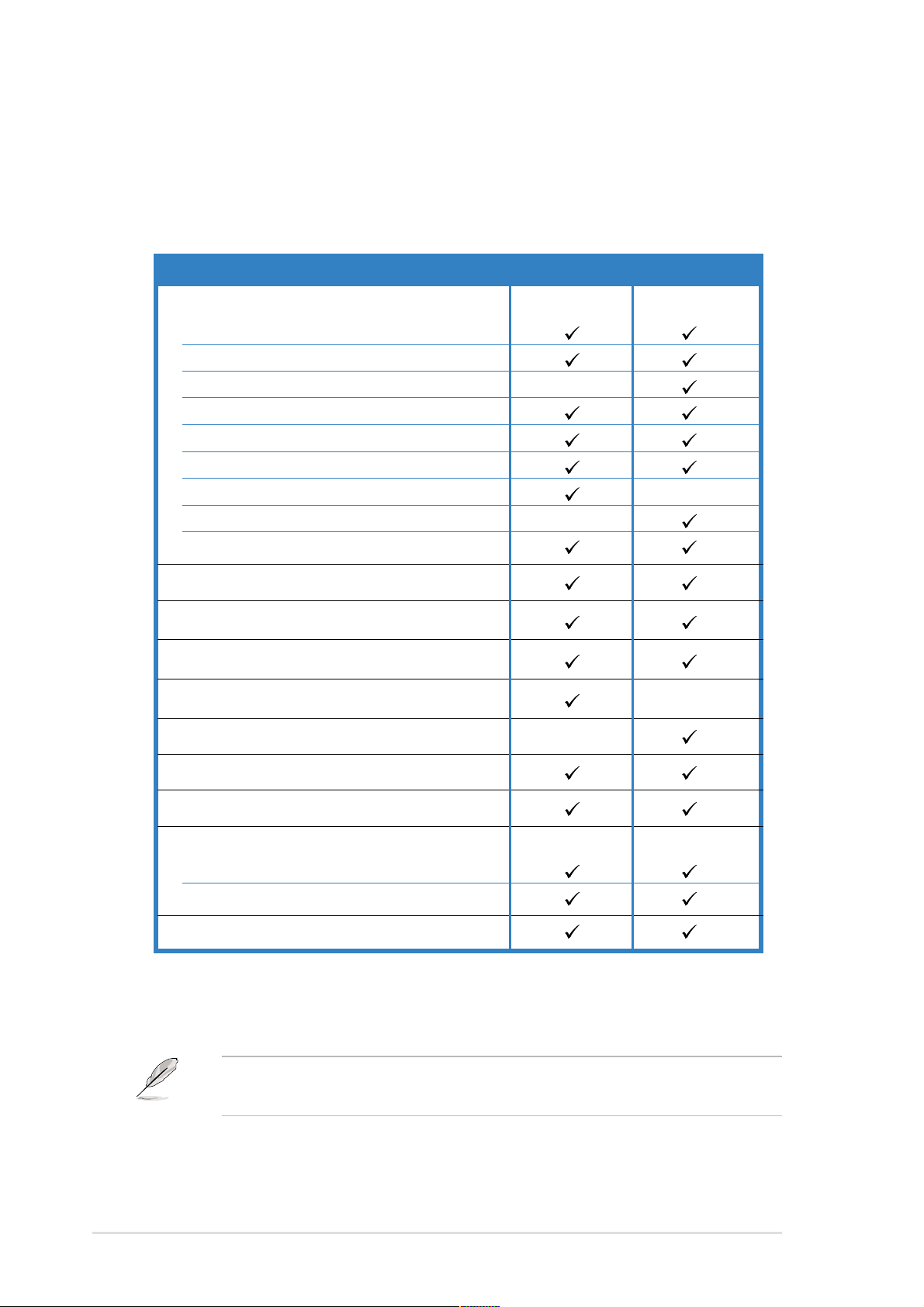
Package items AI2 model AA2 model
ASUS AR13 1U rackmount chassis with:
• ASUS PSCH-LR motherboard
• 300W power supply
• SATA backplane
• Optical drive
• System fan
• Device fan
• 2 x internal HDD trays
• 2 x hot-swap HDD trays
• Pre-connected device/power cables
CPU heatsink
AC power cable
SATA cable
SATA power cable
I2C cable
System screws
Rackmount rail kit
Bundled CDs
• AP140R-E1 drivers and utilities CD
• TrendMicro® ServerProtect® CD
User guide
* AI2 model - supports up to two internal IDE hard disks, or up to two SATA hard disks
* AA2 model - supports up to two hot-swap SATA hard disks
1-2
Contact your dealer immediately if any of the items is damaged or
missing.
Chapter 1: Product introduction
Page 11

1.2 System specifications
The ASUS AP140R-E1 is a 1U barebone server system featuring the
ASUS PSCH-LR motherboard. The server supports the Intel® Pentium® 4
Processor, and includes the latest technologies through the chipsets
embedded on the motherboard.
Chassis Rackmount 1U (AR13)
Motherboard ASUS PSCH-LR
®
Chipset Intel
Processor Supports Intel
Memory 4 x 184-pin DDR sockets for up to 4GB system memory
LAN Intel
VGA ATI RAGE-XL PCI-based VGA controller
E7210 Memory Controller Hub (MCH)
Intel® 6300ESB I/O Controller Hub (ICH)
®
Pentium® 4 with Hyper-Threading Technology,
512K L2 cache, 1MB L3 cache, and 800MHz FSB
Supports PC3200/PC2700/PC2100 unbuffered ECC or
non-ECC DDR DIMMs
®
82547GI Gigabit LAN controller (CSA I/F) for LAN2 port
Intel® 82541GI Gigabit LAN controller (32-bit) for LAN1 port
Expansion slots 2 x 64-bit/66MHz 3V PCI-X slots
Drive bays 1 x 5.25-inch bay (with installed ASUS 52X CD-ROM)
2 x 3.5-inch internal HDD bays
Front I/O 2 x USB 2.0 ports
Power switch
Reset switch
Location switch
Power LED
HDD Access LED
Location LED
Message LED
2 x LAN LEDs
Rear panel I/O 1 x PS/2 keyboard port
1 x PS/2 mouse port
1 x Serial port
1 x VGA port
2 x Gigabit LAN ports (RJ-45)
2 x USB 2.0 ports
Location switch
Location LED
Management ASUS Server Web-based Management (ASWM)
Hardware monitors Voltage, temperature, and fan speed monitoring
Automatic System Restart (ASR) feature
Power supply 300W power supply, 115V/230V, 50Hz/60Hz
Dimensions 620mm (l) x 490mm (w) x 43.6 mm (h))
ASUS AP140R-E1 1U barebone server
1-3
Page 12
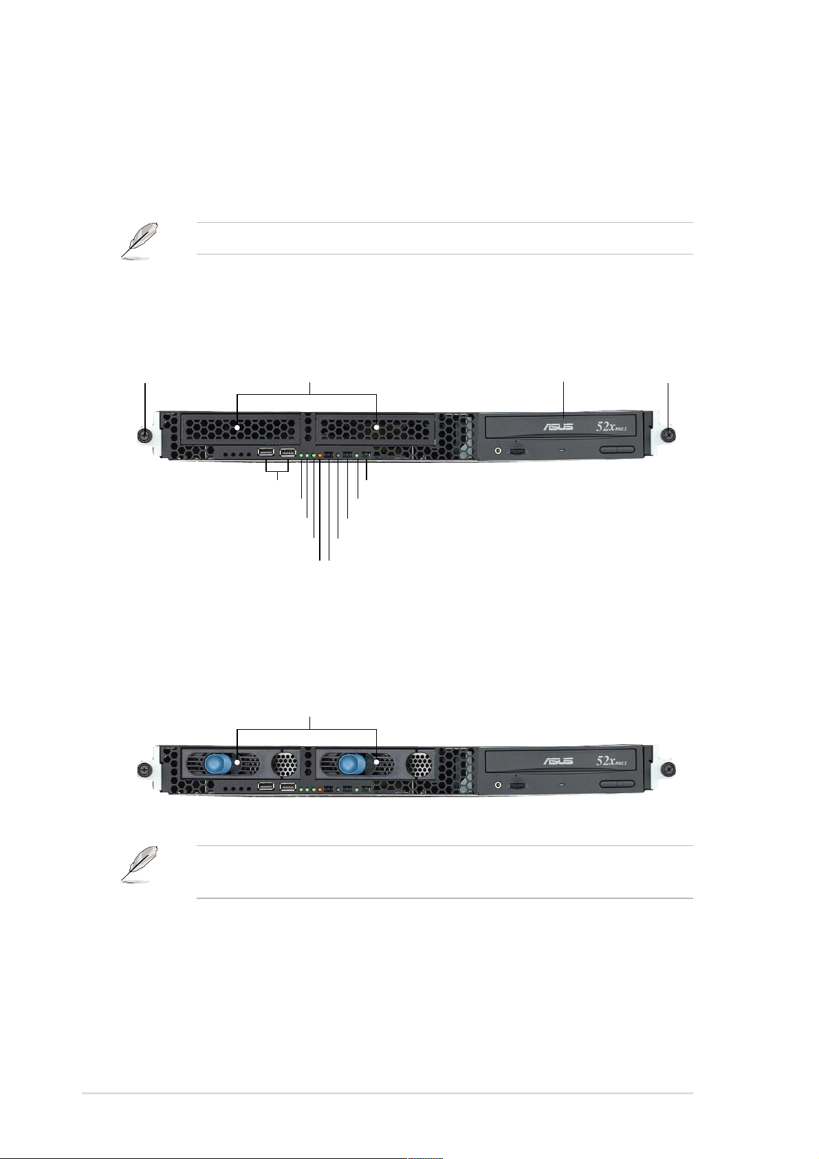
1.3 Front panel features
The barebone server displays a simple yet stylish front panel with easily
accessible features. The power and reset buttons, LED indicators, location
switch, optical drive, and two USB ports are located on the front panel.
Refer to section “1.6.1 Front panel LEDs” for the LED descriptions.
AI2 model
Rack screw Rack screw
USB 2.0 ports
HDD Access LED
Message LED
HDD bays
LAN2 LED
LAN1 LED
Power button
Power LED
Location switch
Location LED
Reset button
CD-ROM drive
AA2 model
Hot-swap HDD bays
1-4
AI2 and AA2 models have the same front panel features except for the
two hot-swap HHD bays present in AA2.
Chapter 1: Product introduction
Page 13
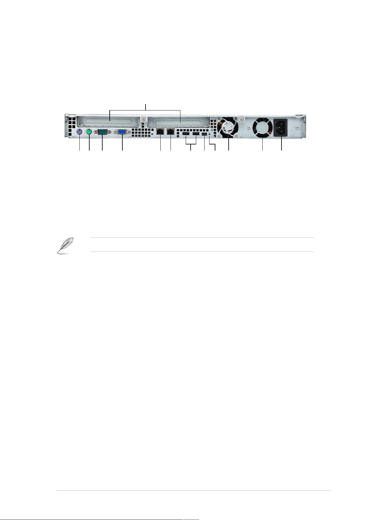
1.4 Rear panel features
The rear panel includes the expansion slots, LAN, VGA, and I/O ports,
fans, and the system power socket.
Expansion slots
PS/2 mouse port
PS/2 keyboard port
Serial port
Refer to section “1.6.2 Rear panel LEDs” for the LED descriptions.
VGA port
Gigabit LAN port (LAN1)
USB 2.0 ports
Gigabit LAN port (LAN2)
Location LED
Location switch
Rear fan
Power supply fan
AC power socket
ASUS AP140R-E1 1U barebone server
1-5
Page 14
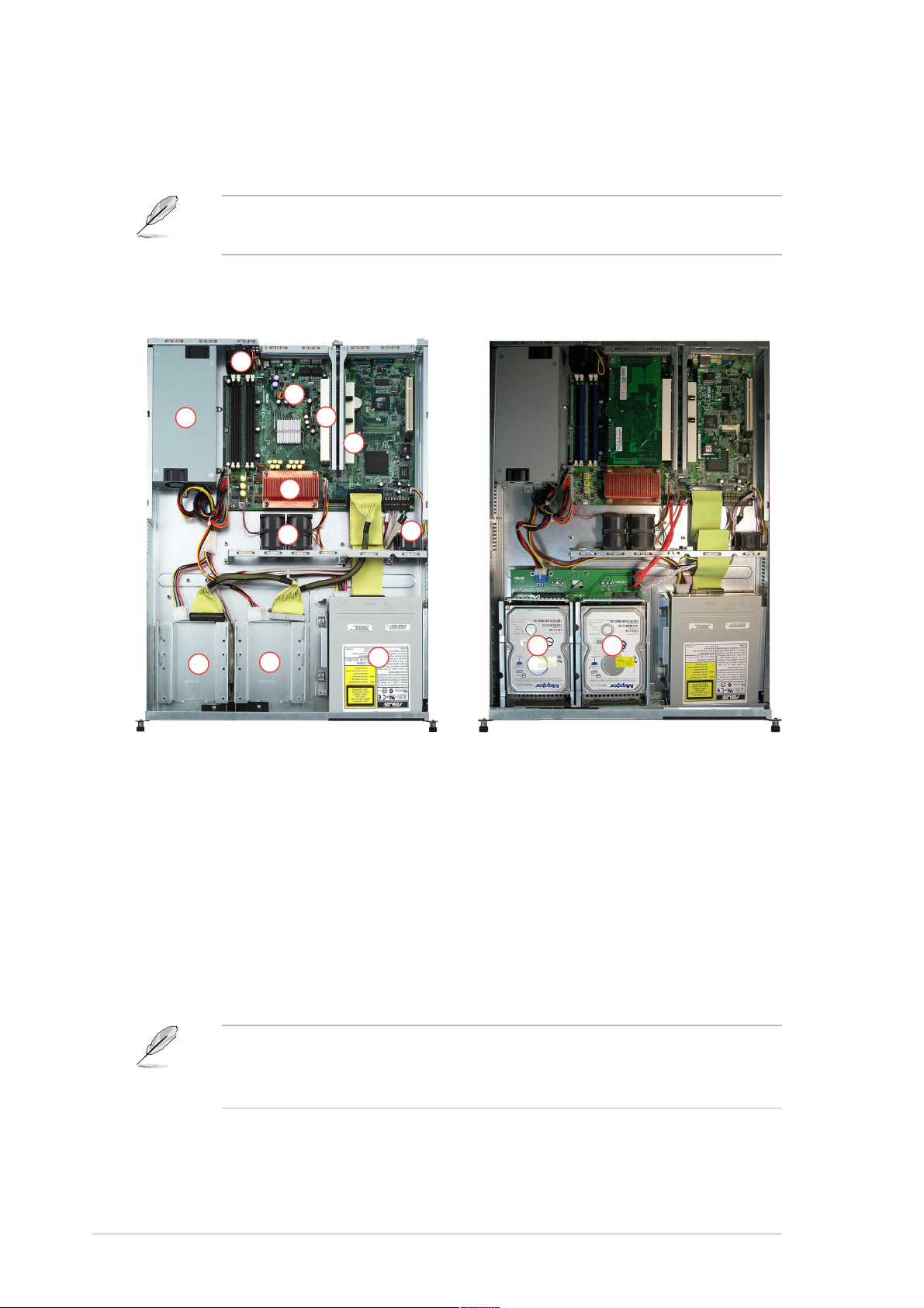
1.5 Internal features
The barebone system includes the basic components as shown.
AI2 and AA2 models have the same internal features except for the
HHD trays.
AI2 model AA2 model
2
3
1
4
5
6
7
9
10
8
11
1. Power supply
2. Rear fan
3. PSCH-LR motherboard
4. PCI-X riser card (PCIX2)
5. PCI-X riser card (PCIX1)
6. CPU heatsink
7. System fans
9 10
8. Device fan
9. AI2: Internal HDD tray 1
AA2: Hot-swap HDD tray 1
10.AI2: Internal HDD tray 2
AA2: Hot-swap HDD tray 2
11. Optical drive
1-6
The barebone system does not include a floppy disk drive. Connect an
external floppy disk drive (USB interface) to any of the USB 2.0 ports
on the front or rear panel if you need to use a floppy disk.
Chapter 1: Product introduction
Page 15
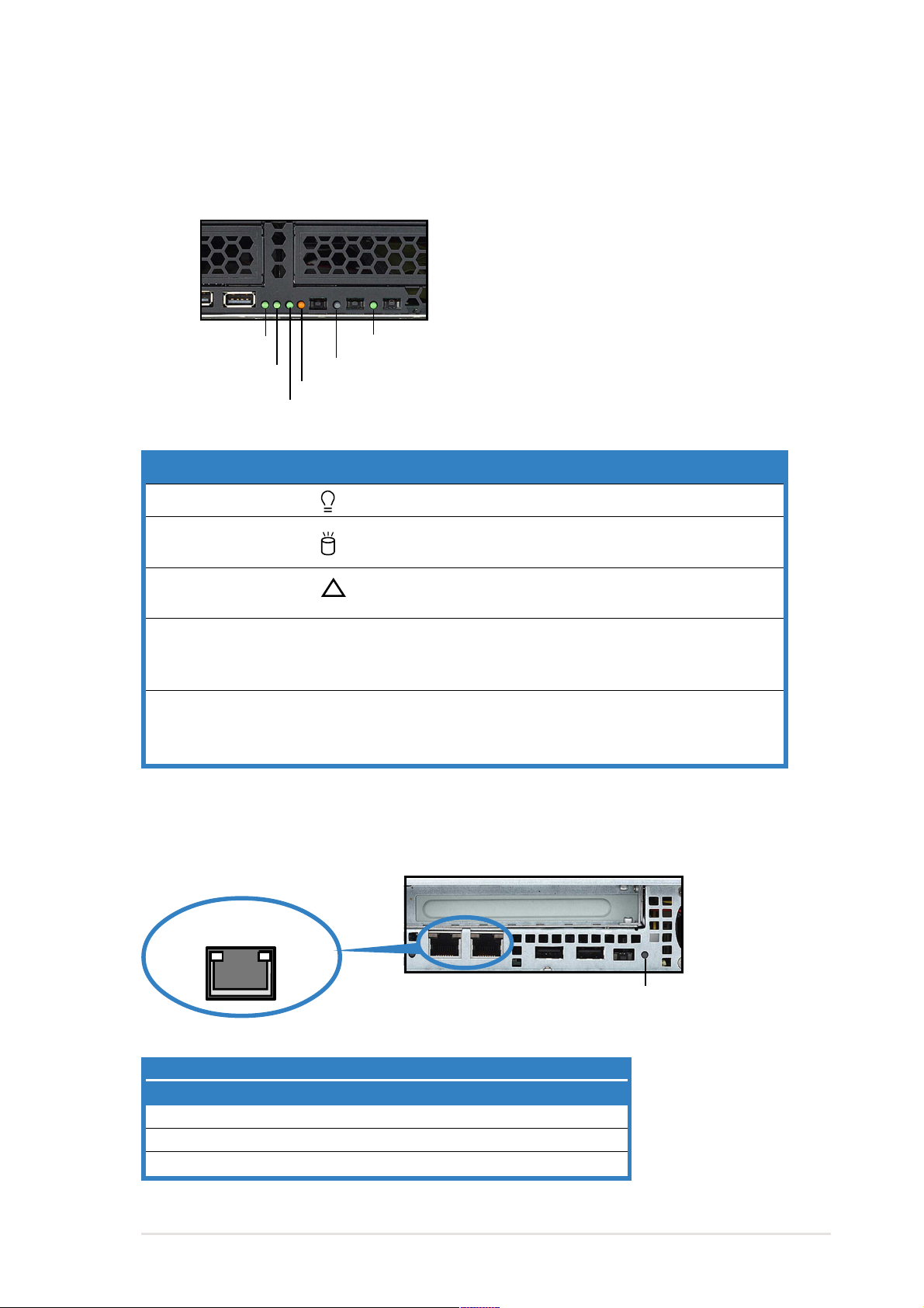
1.6 LED information
1.6.1 Front panel LEDs
HDD Access LED
LAN2 LED
Message LED
LAN1 LED
LED Icon Display status Description
Power LED ON System power ON
HDD Access LED OFF No activity
Message LED OFF System is normal; no incoming event
Location LED OFF Normal status
LAN LED OFF No LAN connection
Power LED
Location LED
Blinking Read/write data into the HDD
!
Blinking ASWM indicates a HW monitor event
ON Location switch is pressed
(Press the location switch again to turn off)
Blinking LAN is transmitting or receiving data
ON LAN connection is present
1.6.2 Rear panel LEDs
RJ-45
SPEEDACT/LNK
Location LED
ACT/LINK LED SPEED LED
Status Description Status Description
OFF No link OFF 10Mbps connection
Green Linked Orange 100Mbps connection
Blinking Linking Green 1000Mbps connection
ASUS AP140R-E1 1U barebone server
1-7
Page 16

1-8
Chapter 1: Product introduction
Page 17

Chapter 2
This chapter lists the hardware setup
procedures that you have to perform when
installing or removing system components.
ASUS AP140R-E1 1U barebone server
Hardware setup
2-1
Page 18
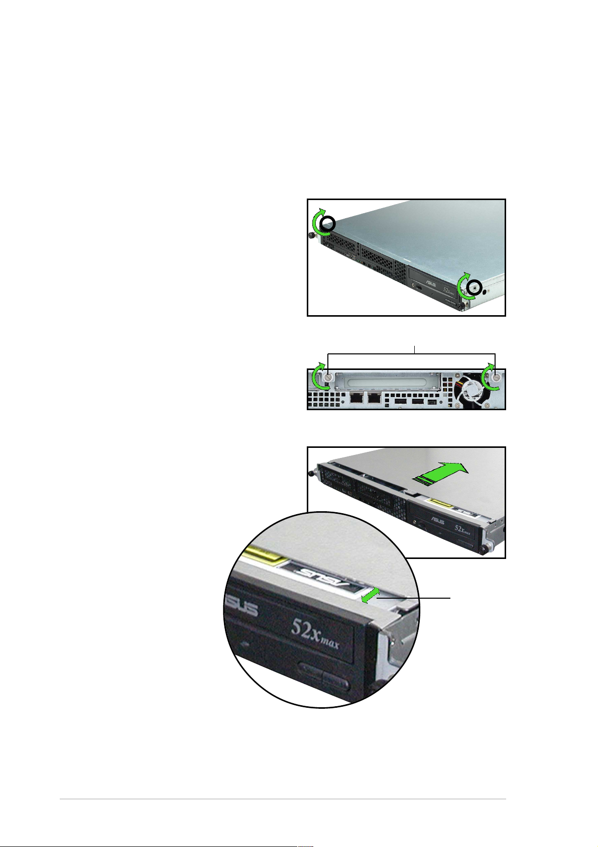
2.1 Chassis cover
Remove the chassis cover to access the internal components or if you
wish to install system devices.
2.1.1 Removing the cover
1. Use a Phillips screwdriver to
remove the screw on each front
end of the top cover.
Thumbscrews
2. Loosen the two thumbscrews on
the rear panel to release the top
cover from the chassis.
2. Firmly hold the cover and slide it
toward the rear panel for about
half an inch until it is disengaged
from the chassis.
3. Lift the cover from the chassis.
1/2 inch
distance
2-2
Chapter 2: Hardware setup
Page 19
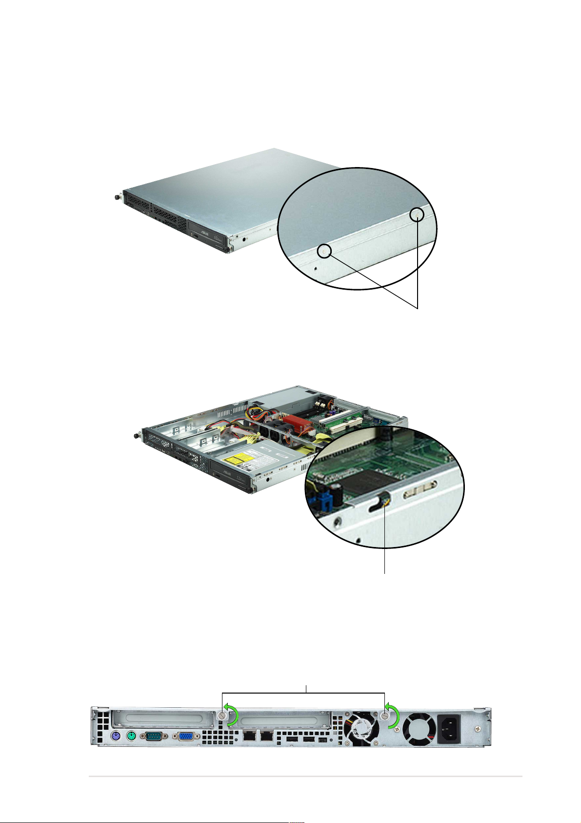
2.1.2 Installing the cover
1. Position the cover on top of the chassis with the thumbscrews on the
rear, and leaving a gap of about half an inch from the front panel.
Side markings
2. Make sure that the side markings on the cover (two on each side) are
aligned to the grooves on the chassis.
Side lock groove
3. Slide the cover toward the front until it snaps in place.
4. Tighten the thumbscrews on the rear to secure the cover.
Thumbscrews
ASUS AP140R-E1 1U barebone server
2-3
Page 20
2.2 Central Processing Unit (CPU)
The motherboard comes with a surface mount 478-pin Zero Insertion
Force (ZIF) socket and designed for the Intel
If your barebone system comes with the CPU heatsink installed,
remove the pre-installed CPU heatsink before installing a CPU as
described in section “2.2.1 Removing the CPU heatsink.”
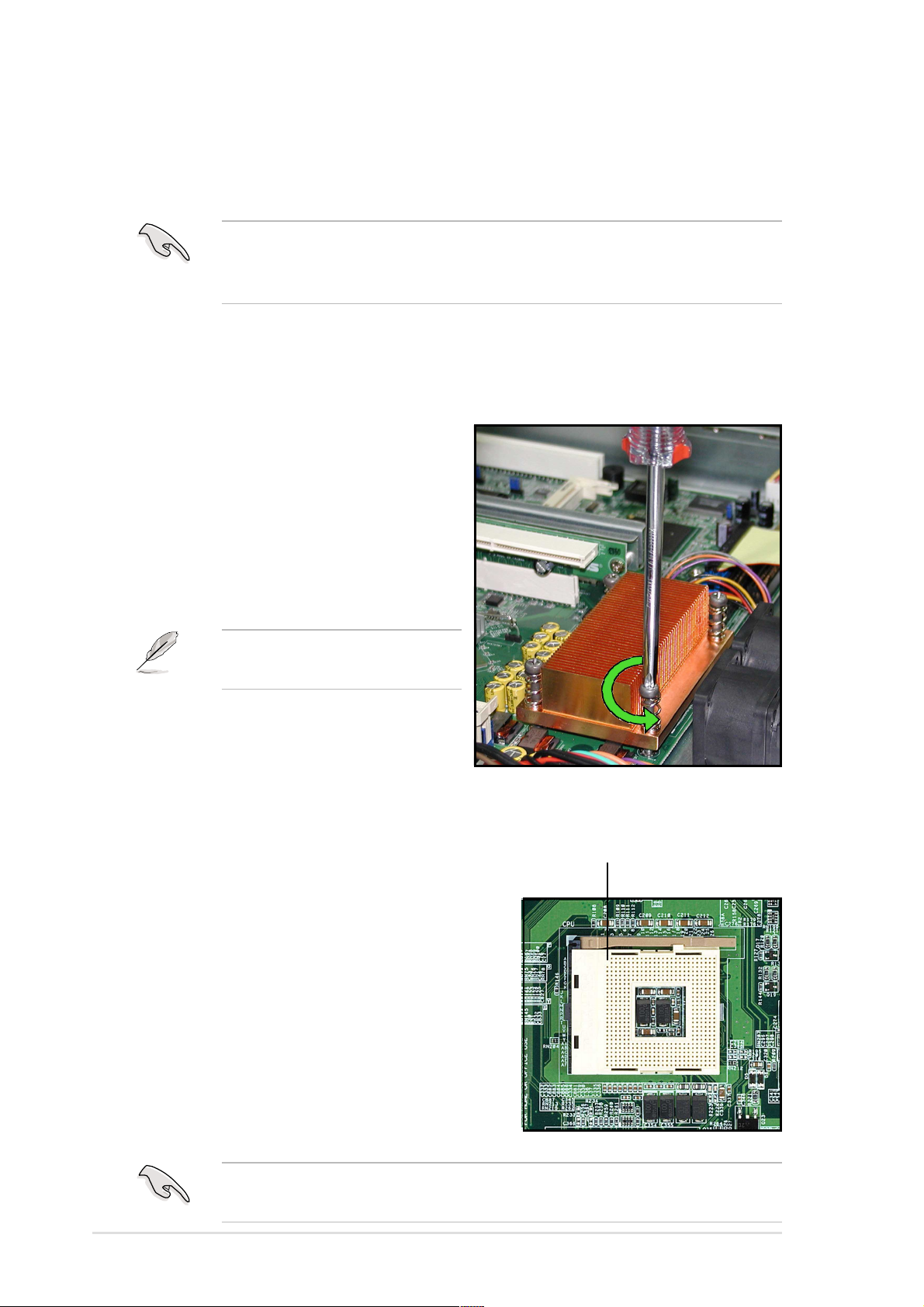
2.2.1 Removing the CPU heatsink
To remove the CPU heatsink:
1. Use a Phillips (cross) screwdriver
to loosen the four screws that
secure the heatsink until it is
released.
2. Carefully lift the heatsink from the
motherboard.
®
Pentium® 4 processor.
You don’t need to detach the
screws from the heatsink.
2.2.2 Installing a CPU
To install a CPU:
1. Locate the CPU socket on the
motherboard and take note of the Pin 1
on the socket.
Pin 1
2-4
Make sure that the socket lever is pushed back all the way, otherwise
the CPU does not fit in completely.
Chapter 2: Hardware setup
Page 21
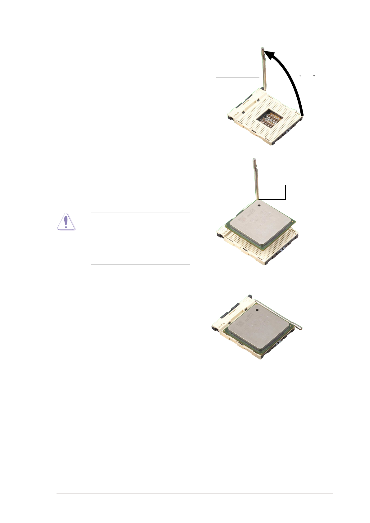
2. Flip up the socket lever and push
it all the way to the other side.
Socket Lever
3. Position the CPU above the
socket as shown.
4. Carefully insert the CPU into the
socket until it fits in place.
The CPU fits only in one
correct orientation. DO NOT
force the CPU into the socket
to prevent bending the pins
and damaging the CPU!
90 -100
Gold Mark
5. Carefully push down the socket
lever to secure the CPU. The lever
clicks on the side tab to indicate
that it is locked.
6. Apply the thermal interface
material (thermal grease) to the
top of the CPU. This thermal
grease should come with the CPU
package.
ASUS AP140R-E1 1U barebone server
2-5
Page 22
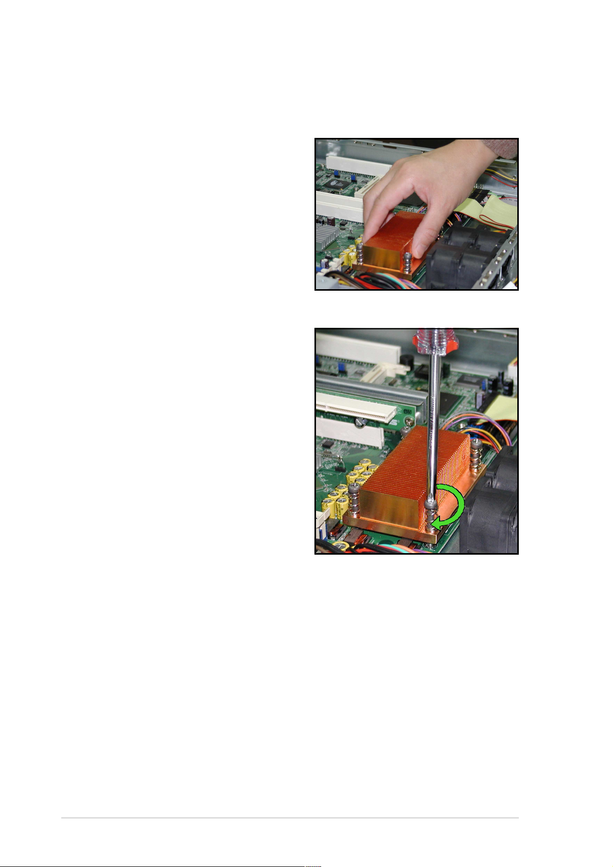
2.2.3 Installing the CPU heatsink
To install the CPU heatsink:
1. Carefully place the heatsink on
top of the installed CPU.
2. Hold down the heatsink lightly
and twist each of the four screws
with a Philips (cross) screwdriver
just enough to attach the heatsink
to the motherboard.
3. When the four screws are
attached, tighten them one by one
to completely secure the heatsink.
2-6
Chapter 2: Hardware setup
Page 23
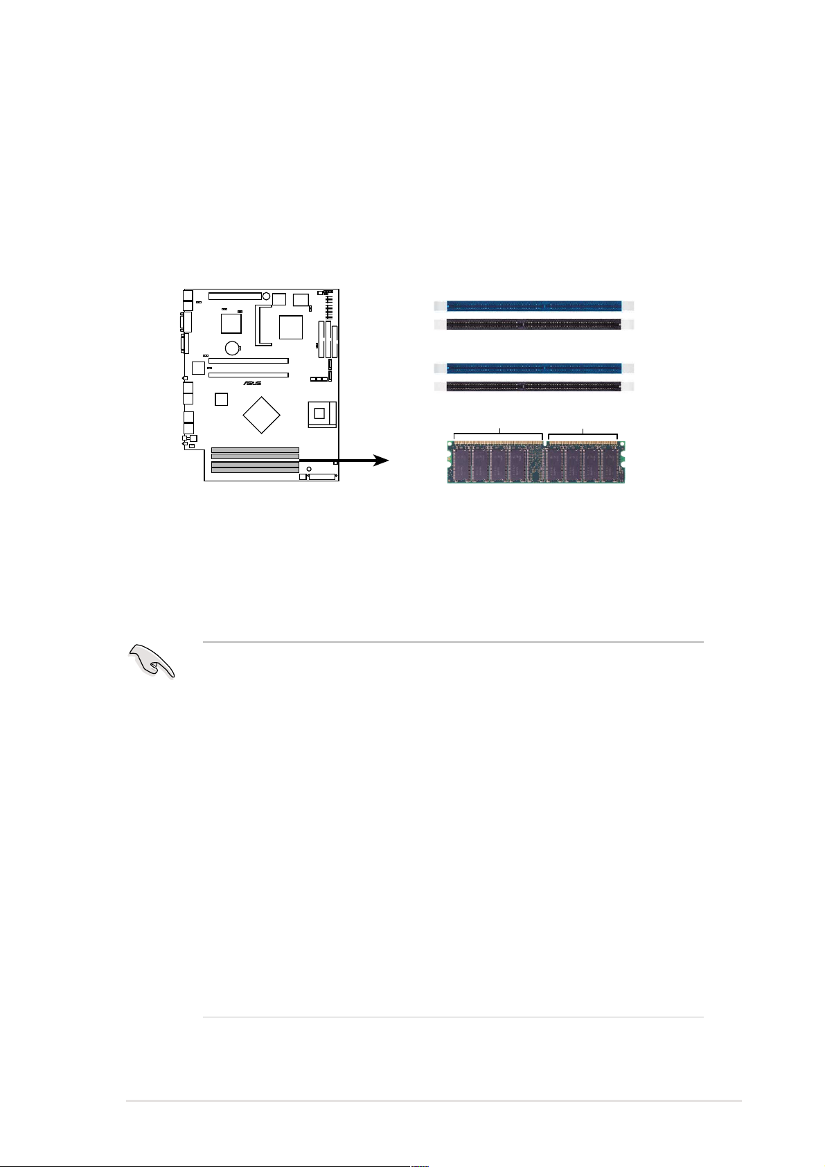
2.3 System memory
The motherboard comes with four Double Data Rate (DDR) Dual Inline
Memory Module (DIMM) sockets. These sockets support up to 4GB
system memory using 184-pin unbuffered ECC or non-ECC PC3200/
PC2700/PC2100 DDR DIMMs.
The following figure shows the location of the DDR DIMM sockets.
DIMM_A1
DIMM_A2
DIMM_B1
®
DIMM_B2
80 Pins104 Pins
PSCH-LR
PSCH-LR 184-Pin DDR DIMM Sockets
2.3.1 Memory configurations
1. Installing DDR DIMMs other than the recommended configurations
may cause memory sizing error or system boot failure. Use any of
the recommended configurations in Table 1.
2. In dual-channel configurations, install only identical (the same
type and size) DDR DIMM pairs for each channel.
3. Always install DIMMs with the same CAS latency. For optimum
compatibility, it is recommended that you obtain memory modules
from the same vendor.
4. Make sure that the memory frequency matches the CPU FSB
(Front Side Bus). Refer to Table 2.
5. DIMMs installed into any three sockets will function in single-
channel mode.
6. When all four sockets are populated with 1GB DIMMs (total 4GB),
the system may detect only about 3.6GB (less than 4GB) due to
ICH resource allocation.
ASUS AP140R-E1 1U barebone server
2-7
Page 24
Table 1 Recommended memory configurations
SOCKETS
Mode DIMM_A1 DIMM_A2 DIMM_B1 DIMM_B2
(blue) (black) (blue) (black)
Single-channel (1) Populated — — —
(2) — Populated — —
(3) — — Populated —
(4) — — — Populated
Dual-channel (1) Populated — Populated —
(2) — Populated — Populated
(3)* Populated Populated Populated Populated
*
For dual-channel configuration (3), you may:
• install identical DIMMs in all four sockets
or
• install identical DIMM pair in DIMM_A1 and DIMM_B1 (blue sockets)
and identical DIMM pair in DIMM_A2 and DIMM_B2 (black sockets)
Table 2 Memory frequency/CPU FSB synchronization
CPU FSB DDR DIMM Type Memory Frequency
800 MHz PC3200/PC2700/PC2100 400/333/266 MHz
533 MHz PC2700/PC2100 333/266 MHz
400 MHz PC2100 266 MHz
2-8
Chapter 2: Hardware setup
Page 25
2.3.2 Installing a DIMM
Make sure to unplug the power supply before adding or removing
DIMMs or other system components. Failure to do so may cause
damage to both the motherboard and the components!
Follow these steps to install a DIMM.
To access the DIMM sockets, remove the upper HDD fan cage. Refer
to section “2.10 Removable components” for instructions.
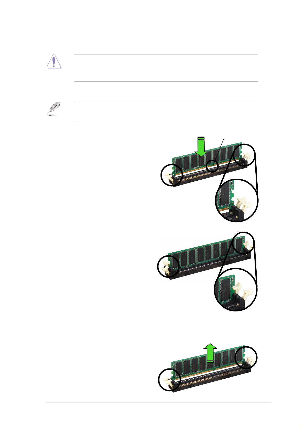
1. Unlock a DIMM socket by
pressing the retaining clips
outward.
2. Align a DIMM on the socket such
that the notch on the DIMM
matches the break on the socket.
Unlocked Retaining Clip
3. Firmly insert the DIMM into the
socket until the retaining clips
snap back in place and the DIMM
is properly seated.
DDR DIMM notch
Locked Retaining Clip
2.3.3 Removing a DIMM
Follow these steps to remove a DIMM.
1. While supporting the DIMM with
your fingers, press the retaining
clips outward simultaneously to
release the DIMM from the socket.
2. Remove the DIMM from the
socket.
ASUS AP140R-E1 1U barebone server
2-9
Page 26
2.4 Hard disk drives
2.4.1 Installing an IDE hard disk drive
To install an IDE HDD:
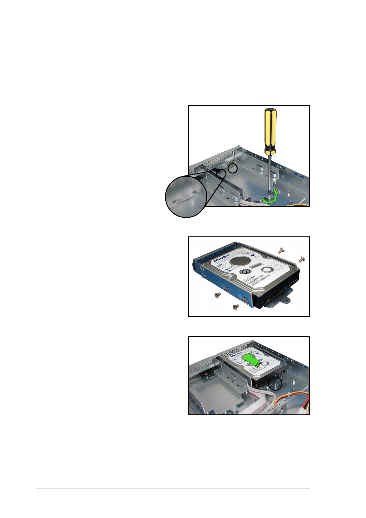
1. Use a Phillips (cross) screwdriver
to remove the screw that secures
the hard disk tray to the chassis.
Slide the tray backward until the
two tray lock tabs are disengaged.
Lift the tray from the bay.
Lock tab
2. Place a hard disk drive into the
drive tray, and secure it with four
screws.
(AI2 model)
3. Carefully place the tray with
installed hard disk drive into the
drive bay. Slide it forward until the
front end aligns with the front
panel, and the screw hole
matches the standoff.
2-10
Chapter 2: Hardware setup
Page 27
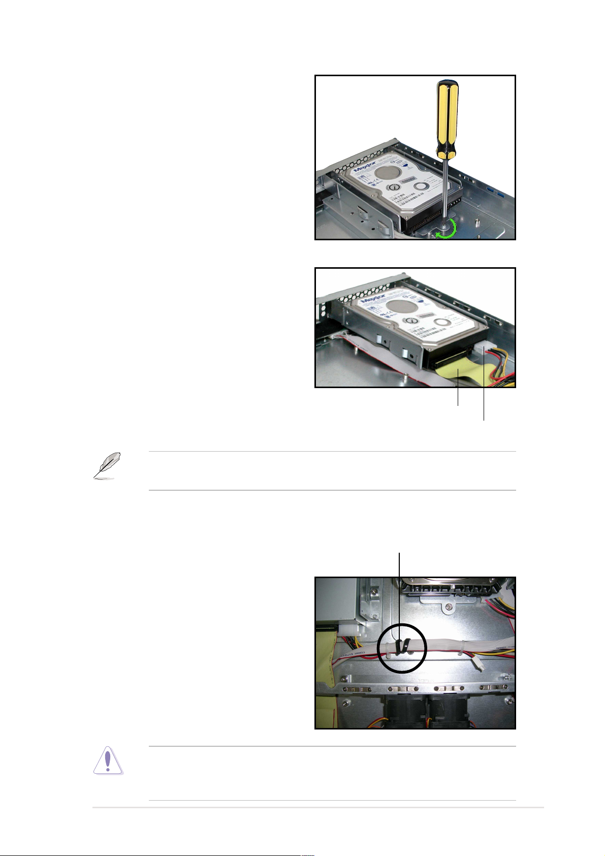
4. Secure the tray with a screw.
5. Connect the 40-pin IDE cable and
a 4-pin power plug to their
respective connectors on the
back of the drive.
40-pin IDE cable
4-pin power plug
The other end of the IDE cable is pre-connected to the primary IDE
connector on the motherboard.
6. Repeat steps 1 to 5 to install a second IDE drive.
7. When finished installing devices,
Cable clamp
join the power and signal cables
together with the cable clamp to
prevent interference to the
rotating fan blades.
Ensure that all cables are held together with the cable clamp, specially
those near the system fans. Loose cables may get caught with the fan
blades causing fan failure!
ASUS AP140R-E1 1U barebone server
2-11
Page 28
2.4.2 Installing a SATA hard disk drive
(AI2 model)
To install an SATA HDD:
1. Follow steps 1 to 4 in section
“2.4.1 Installing an IDE hard disk
drive.”
2. Connect the 7-pin SATA cable to
the SATA connector on the back
of the drive. Connect the other
end to an SATA connector on
the motherboard.
SATA connector
7-pin SATA cable
4-pin device power cable
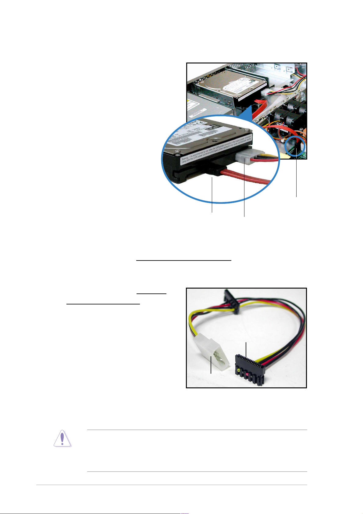
3. Connect the HDD power cable.
• For Serial ATA HDDs
with a 4-pin power connector
, connect a 4-pin
(female) device plug from the power supply to the 4-pin (male) power
connector on the back of the drive as shown above.
• For Serial ATA HDDs
4-pin power connector
without a
, use an
SATA power cable with a 4-pin/
15pin plugs. Connect a 4-pin
(female) device plug from the
15-pin
power supply to the 4-pin (male)
plug of the SATA power cable.
Connect the 15-pin SATA power
plug to the power connector on
the back of the drive.
4-pin (male)
4. Repeat steps 1 to 3 to install a second SATA drive.
Ensure that all cables are held together with the cable clamp, specially
those near the system fans. Loose cables may get caught with the fan
blades causing fan failure! See step 7 of section “2.4.1 Installing an
IDE hard disk drive.”
2-12
Chapter 2: Hardware setup
SATA power cable
Page 29
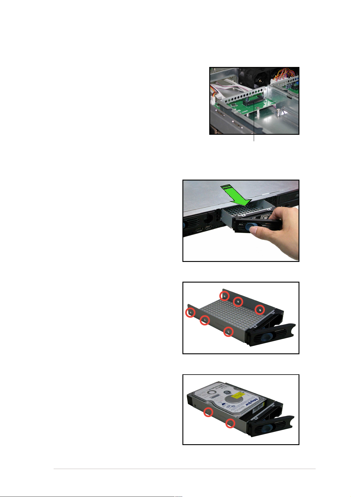
2.4.3 Installing a hot-swap SATA HDD
System models with hot-swap drive trays
(AA2 model) include a SATA backplane that
connects to the internal SATA connectors.
This configuration allows you to easily install
or replace SATA HDDs.
SATA backplane connector
To install a hot-swap SATA HDD:
1. Release a drive tray by pushing
the spring lock to the right, then
pulling the tray lever outward. The
drive tray ejects slightly after you
pull out the lever.
(AA2 model)
2. Firmly hold the tray lever and pull
the drive tray out of the bay.
3. Take note of the drive tray holes.
Each side has three holes to fit
different types of hard disk. Use
two screws on each side to
secure a hard disk.
4. Place a SATA hard disk on the
drive tray, and secure it with four
screws.
ASUS AP140R-E1 1U barebone server
2-13
Page 30
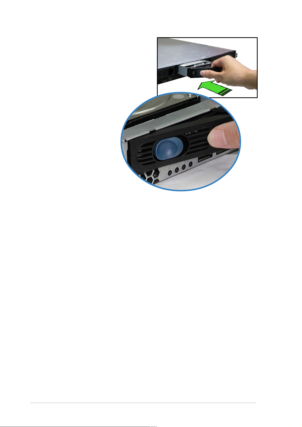
5. Carefully insert the drive tray and
push it all the way to the depth of
the bay until just a small fraction of
the tray edge protrudes.
6. Push the tray lever until it clicks,
and secures the drive
tray in place. The
drive tray is correctly
placed when its front
edge aligns with the
bay edge.
2-14
Chapter 2: Hardware setup
Page 31

2.5 Expansion cards
The system comes with two PCI-X riser card brackets that you may
remove separately if you wish to install PCI cards.
• The riser card brackets have different orientation. For illustration
purposes, the riser card brackets will be referred to as right
bracket and left bracket.
• The PCI-X slots on the riser cards support 3V universal-type 32-bit/
64-bit PCI cards.
2.5.1 Installing a PCI card
To install a PCI card:
1. Firmly hold a riser card bracket,
then pull it up to detach it from the
PCI-X slot on the motherboard.
2. Use a Phillips (cross) screwdriver
to remove the screw that secures
the slot metal cover.
Right bracket
Left bracket
3. Install a PCI card to the left
bracket as shown, then secure
the card with a screw.
ASUS AP140R-E1 1U barebone server
2-15
Page 32

4. Install the left bracket with the
card into the PCI-X slot on the
motherboard. Make sure that the
golden connectors completely fit
the slot and the bracket aligns
with the rear panel.
5. If you wish to install a second PCI
card, repeat steps 1 and 2 then
install the card to the right
bracket as shown. Secure the
card with a screw.
6. Install the right bracket with the
card into the PCI-X slot on the
motherboard. Make sure that the
golden connectors completely fit
the slot and the bracket aligns
with the rear panel.
When properly installed, the riser
card brackets with PCI cards
appear as shown.
7. Connect the cable(s) to the cards, if applicable.
2-16
Chapter 2: Hardware setup
Page 33

2.5.2 Configuring an expansion card
After installing the expansion card, configure the it by adjusting the
software settings.
1. Turn on the system and change the necessary BIOS settings, if any.
See Chapter 5 for information on BIOS setup.
2. Assign an IRQ to the card. Refer to the following tables.
3. Install the software drivers for the expansion card.
Standard interrupt assignments
IRQ Priority Standard Function
0 1 System Timer
1 2 Keyboard Controller
2 N/A Programmable Interrupt
3* 11 Communications Port (COM2)
4* 12 Communications Port (COM1)
5* 13 Sound Card (sometimes LPT2)
6 14 Floppy Disk Controller
7* 15 Printer Port (LPT1)
8 3 System CMOS/Real Time Clock
9* 4 ACPI Mode when used
10* 5 IRQ Holder for PCI Steering
11* 6 IRQ Holder for PCI Steering
12* 7 PS/2 Compatible Mouse Port
13 8 Numeric Data Processor
14* 9 Primary IDE Channel
15* 10 Secondary IDE Channel
* These IRQs are usually available for ISA or PCI devices.
IRQ assignments for this motherboard
INTA# INTB# INTC# INTD#
PCIX slot 1 PIRQB# ———
PCIX slot 2 PIRQA# ———
Onboard LAN controller PXIRQ0# PXIRQ1# PXIRQ2# PXIRQ3#
Onboard VGA controller PXIRQ1# PXIRQ2# PXIRQ3# PXIRQ0#
When using PCI cards on shared slots, ensure that the drivers support
“Share IRQ” or that the cards do not need IRQ assignments.
Otherwise, conflicts will arise between the two PCI groups, making the
system unstable and the card inoperable.
ASUS AP140R-E1 1U barebone server
2-17
Page 34

2.6 Cable connections
Refer to this section when reconnecting cables to ensure correct cable
connections.
The bundled system cables are pre-connected before shipment. You
do not need to disconnect these cables unless you will remove preinstalled components to install additional devices.
AI2 model
1
2
5
3
9
4
10
6
7 8
11
Pre-connected system cables
1. Rear fan connector (FAN5)
2. 4-pin 12V power connector (from power supply to motherboard)
3. 20-pin ATX power connector (from power supply to motherboard)
4. System fan connector (FAN6)
5. System fan connectors (FAN2, FAN3, FAN4)
6. Device fan connector (FAN1)
7. Panel connector for front panel LEDs
2-18
8. Front panel USB 2.0 (2 ports)
9. Primary IDE (from motherboard to HDDs)
10. Secondary IDE (from motherboard to optical drive)
11. 4-pin power connector (from power supply to optical drive)
Chapter 2: Hardware setup
Page 35

AA2 model
12
2
3
4
1
10
11
5
6
7
8
9
Pre-connected system cables
1. Rear fan connector (FAN5)
2. 4-pin 12V power connector (from power supply to motherboard)
3. 20-pin ATX power connector (from power supply to motherboard)
4. System fan connector (FAN6)
5. System fan connectors (FAN2, FAN3, FAN4)
6. Device fan connector (FAN1)
7. Panel connector for front panel LEDs
8. Front panel USB 2.0 (2 ports)
9. Secondary IDE (from motherboard to optical drive)
10. SATA cables (from motherboard to SATA backplane)
2
11. I
12. 4-pin power connector (from power supply to SATA backplane)
C cable (from motherboard to SATA backplane)
ASUS AP140R-E1 1U barebone server
2-19
Page 36

2.7 Removable components
You may need to remove previously installed system components when
installing or removing system devices, or when you need to replace
defective components. This section tells how to remove the following
components:
1. System fans 4. Power supply module
2. Device fan 5. Optical drive
3. Rear fan 6. Motherboard
2.7.1 System fans
To uninstall the system fans:
1. Disconnect the system fan cables
from the connectors labeled
FAN2, FAN3, FAN4, and FAN6 on
the motherboard.
2. Remove the four screws that
secure a 40mm x 56mm system
fan.
FAN4
FAN6
FAN3
FAN2
FAN2
FAN3
FAN4
3. Repeat step 2 to uninstall the
other 40mm x 56mm system fan.
FAN6
2.7.2 Device fan
To uninstall the device fan:
1. Disconnect the system fan cable from the connector
labeled FAN1 on the motherboard.
2. Remove the four screws that secure the 40mm x
28mm device fan.
2.7.3 Rear fan
To uninstall the rear fan:
1. Disconnect the system fan cable from the
connector labeled FAN5 on the motherboard.
FAN1
FAN5
2. From the rear panel, remove the four screws that
secure the 40mm x 28mm rear fan.
2-20
Chapter 2: Hardware setup
Page 37

2.7.4 Power supply module
To uninstall the power supply module:
1. Disconnect all the power cables
connected to the motherboard
and system devices.
2. Use a Phillips (cross) screwdriver
to remove the screw the secures
the front end of the power supply.
3. From the rear panel, remove the
two screws the secure the rear
end of the power supply.
4. Slide the power supply forward for about half an inch, then carefully lift
it out from the chassis.
ASUS AP140R-E1 1U barebone server
2-21
Page 38

2.7.5 Optical drive
To uninstall the optical drive:
1. Disconnect the power and signal
cables connected to the rear of
the optical drive.
2. Use a Phillips (cross) screwdriver
to remove the two screws that
secure the meal bracket on the
side of the optical drive. Remove
the bracket to release the drive.
3. Slide the optical drive toward the
front panel, then carefully pull it
out of the drive bay.
2-22
Chapter 2: Hardware setup
Page 39

To install an optical drive:
1. From the front panel, insert the
rear end of the optical drive into
the 5.25-inch drive bay.
2. Place the metal bracket parallel to the side of the optical drive,
matching its two pegs with the lower holes, and the bracket holes with
the standoffs on the base of the chassis.
The metal bracket should fit completely to ensure that the optical drive
is securely in place.
Drive holes to match the
pegs on the metal bracket
Standoffs to match the
holes on the metal bracket
3. Secure the bracket with two
screws.
Drive metal bracket
Bracket pegs
Holes to match the standoffs
ASUS AP140R-E1 1U barebone server
2-23
Page 40

2.7.6 Motherboard
To uninstall the motherboard:
1. Disconnect all the power and signal cables connected to the
motherboard. Refer to section “2.6 Cable connections” for the location
of the cables.
2. Uninstall all the devices from the motherboard including the CPU and
heatsink, riser card brackets, and DDR DIMMs. Refer to the
corresponding sections for instructions on removing these
components.
3. Use a Phillips (cross) screwdriver to remove the ten (10) screws that
secure the motherboard to the base of the chassis. The locations of the
screw holes are indicated in the following figure.
4. Carefully lift the motherboard out of the chassis.
To install a motherboard, position the I/O connectors toward the rear
panel then carefully fit the motherboard to the base of the chassis.
Secure the motherboard with ten screws on the holes indicated in the
above figure.
2-24
Chapter 2: Hardware setup
Page 41

Chapter 3
This chapter describes the optional
installation procedures for the barebone
server.
ASUS AP140R-E1 1U barebone server
Installation options
2-1
Page 42

3.1 Rackmount rail kit items
Your rackmount rail kit package contains two pairs of rails (one pair for
each side of the barebone system), and eight (8) pairs of nut-and-bolt type
screws.
Nuts
Bolts
Left pair
Right pair
3.2 Rack rails assembly
To assemble the rack rails:
1. Determine the depth of the rack where you wish to install the system.
2. Match one long and one short rail to your desired length, and fix them
together using four (4) pairs of nuts and bolts.
3. Repeat step 2 to assemble the other rail pair.
Rear ends
Bolts on inner side
Nuts on outer side
3-2
Front ends
Chapter 3: Installation options
Page 43

3.3 Attaching the rails to the rack
To attach the rails to the rack:
1. Select one unit of space (1U) on the
rack where you wish to install the
barebone server.
2. Remove the screws from the 1U space
on the rack front.
3. Align the front end holes of a rack rail
pair to the 1U space.
4. Drive in two screws on the outer holes
to secure the front end.
1U space
5. Find the rear 1U space that corresponds to the front 1U space where
you attached the rail.
6. Remove the screws from the rear 1U space, and align the rear end
holes.
7. Drive in two screws on the outer holes to secure the rear end.
8. From the rack front, find the corresponding 1U space for the second
rail pair.
9. Repeat steps 2 to 7 to attach the second rail pair. When properly
installed, the rack rails appear as shown.
ASUS AP140R-E1 1U barebone server
3-3
Page 44

3.4 Rackmounting the server
To mount the server to the rack:
1. Firmly hold the server on both sides and insert the rear panel side to
the front end of the rack rail.
2. Carefully push the server all the way to the back until the front panel
fits the front end of the rack, and the rack screws on the server match
the middle hole on the rack.
3. Tighten the two rack screws to secure
the server to the rack.
Rack screw
3-4
Chapter 3: Installation options
Page 45

Chapter 4
This chapter includes the motherboard
layout, and brief descriptions of the jumpers
and internal connectors.
ASUS AP140R-E1 1U barebone server
Motherboard info
2-1
Page 46

4.1 Motherboard layout
25cm (9.9in)
PS2_KB1PS2_MS1
COM1
VGA1
MLED1
LAN1
LAN2
KBPWR1
Intel
82541GI
LAN_EN2
RECOVERY1
LAN_EN1
Intel
82547GI
PCI1
VGA_EN1
ATI
RAGE-XL
VGA
Controller
CR2032 3V
Lithium Cell
CMOS Power
PCIX1
PCIX2
BUZZER1
BMCSOCKET1
4Mbit
Firmware
Hub
Intel
6300ESB
ICH
Super
I/O
FAN1
CHASSIS1
PRI_IDE1
CLRTC1
FAN3FAN4
FAN2
J3
SEC_IDE1
SATA2
SATA1
BPSMB1
USB34PANEL1
FLOPPY1
31.1cm (12.2in)
USB1
USB2
LOCLED1
SW1
Intel
E7210
MCH
PSCH-LR
FAN5
DDR DIMM_A1 (64/72 bit,184-pin module)
DDR DIMM_A2 (64/72 bit,184-pin module)
DDR DIMM_B1 (64/72 bit,184-pin module)
DDR DIMM_B2 (64/72 bit,184-pin module)
ATX12V1
SB_PWR1
ATX Power Connector
FAN6
• The PCI1 slot is used for debugging card only.
• The BMCSOCKET1 slot is reserved for a server management
card.
Socket 478
4-2
Chapter 4: Motherboard information
Page 47

Layout contents
Jumpers
1. Keyboard power (3-pin KBPWR1) 4-4
2. Gigabit LAN1 controller setting (3-pin LAN_EN1) 4-4
3. Gigabit LAN2 controller setting (3-pin LAN_EN2) 4-5
4. Onboard VGA setting (3-pin VGA_EN1) 4-5
5. Recovery setting (3-pin RECOVERY1) 4-6
6. Clear RTC RAM (3-pin CLRTC1) 4-7
Internal connectors
1. Floppy disk drive connector (34-1 pin FLOPPY1) 4-8
2. SMBus connector (6-1 pin BPSMB1) 4-8
3. IDE connectors (40-1 pin PRI_IDE [blue], SEC_IDE [black]) 4-9
4. Serial ATA connectors (7-pin SATA1, SATA2) 4-10
5. ATX power connectors (20-pin, 4-pin) 4-11
6. LED connector (2-pin J3) 4-11
7. Fan connectors (3-pin FAN1/2/3/4/5/6) 4-12
8. Chassis intrusion connector (4-1 pin CHASSIS1) 4-12
9. USB header (10-1 pin USB34) 4-13
10. System panel connector (20-1 pin PANEL1) 4-13
- LAN connection indicators (2-pin LAN1_LED, LAN2_LED) 4-14
- Hard disk activity LED (2-pin IDE_LED) 4-14
- Front panel location LED (2-pin FP_LOCLED) 4-14
- System power LED (2-pin PWR_LED) 4-14
- Reset switch (2-pin RESET) 4-14
- ATX power button/ Soft-off switch (2-pin PWRBTN) 4-14
- Message LED (2-pin MSG_LED) 4-14
- Front panel location switch (2-pin FP_LOCSW) 4-14
ASUS AP140R-E1 1U barebone server
4-3
Page 48

4.2 Jumpers
1. Keyboard power (3-pin KBPWR1)
This jumper allows you to enable or disable the keyboard wake-up
feature. Set this jumper to pins 2-3 (+5VSB) if you wish to wake up the
computer when you press a key on the keyboard (the default is the
Space Bar). This feature requires an ATX power supply that can supply
at least 1A on the +5VSB lead, and a corresponding setting in the
BIOS (see section 4.5.1 Power Up Control).
KBPWR1
23
PSCH-LR
12
No KB Wake-Up KB Wake-Up
®
(Default)
PSCH-LR Keyboard Power Setting
2. Gigabit LAN1 controller setting (3-pin LAN_EN1)
This jumper allows you to enable or disable the Intel
®
82541GI Gigabit
LAN controller. Setting this jumper to pins 2-3 disables the Gigabit LAN
port (RJ-45) on the rear panel that corresponds to this controller.
®
PSCH-LR
PSCH-LR LAN_EN1 Setting
LAN_EN1
Enable
(Default)
2312
Disable
4-4
Chapter 4: Motherboard information
Page 49

3. Gigabit LAN2 controller setting (3-pin LAN_EN2)
This jumper allows you to enable or disable the Intel
®
82547GI Gigabit
LAN controller. Setting this jumper to pins 2-3 disables the Gigabit LAN
port (RJ-45) on the rear panel that corresponds to this controller.
LAN_EN2
®
2312
Enable
(Default)
PSCH-LR
Disable
PSCH-LR LAN_EN2 Setting
4. Onboard VGA setting (3-pin VGA_EN1)
This jumper allows you to enable or disable the onboard VGA. Set this
jumper to disabled (pins 2-3) if you wish to install a VGA card.
VGA_EN1
2312
PSCH-LR
®
Enable
(Default)
Disable
PSCH-LR VGA Jumper Setting
ASUS AP140R-E1 1U barebone server
4-5
Page 50

5. Recovery setting (3-pin RECOVERY1)
This jumper allows you to update/recover the BIOS quickly.
To update the BIOS:
1. Prepare a floppy disk that contains the latest BIOS for the
motherboard (xxxx-xxx.BIN) and the AWDFLASH.EXE utility.
2. Set the jumper to pins 2-3.
3. Insert the floppy disk then turn on the system to update the BIOS.
4. Shut down the system.
5. Set the jumper back to pins 1-2.
6. Turn on the system.
RECOVERY1
2312
®
PSCH-LR
PSCH-LR RECOVERY Setting
Normal
(Default)
Recovery
4-6
Chapter 4: Motherboard information
Page 51

6. Clear RTC RAM (3-pin CLRTC1)
This jumper allows you to clear the Real Time Clock (RTC) RAM in
CMOS. You can clear the CMOS memory of date, time, and system
setup parameters by erasing the CMOS RTC RAM data. The RAM
data in CMOS, that include system setup information such as system
passwords, is powered by the onboard button cell battery.
To erase the RTC RAM:
1. Turn OFF the computer and unplug the power cord.
2. Remove the onboard battery.
3. Move the jumper cap from pins 1-2 (default) to pins 2-3. Keep the
cap on pins 2-3 for about 5~10 seconds, then move the cap back
to pins 1-2.
4. Re-install the onboard battery.
5. Plug the power cord and turn ON the computer.
6. Hold down the <Del> key during the boot process and enter BIOS
setup to re-enter data.
®
PSCH-LR
PSCH-LR Clear RTC RAM
Except when clearing the RTC RAM, never remove the cap on CLRTC
jumper default position. Removing the cap will cause system boot
failure!
CLRTC1
3
22
1
Normal
(Default)
Clear CMOS
ASUS AP140R-E1 1U barebone server
4-7
Page 52

4.3 Connectors
This section describes the internal connectors on the motherboard.
Refer to section “1.4 Rear panel features” for information on the
external (rear panel) connectors.
1. Floppy disk drive connector (34-1 pin FLOPPY1)
This connector supports the provided floppy drive ribbon cable. After
connecting one end to the motherboard, connect the other end to the
floppy drive. (Pin 5 is removed to prevent incorrect insertion when
using ribbon cables with pin 5 plug).
FLOPPY1
NOTE: Orient the red markings on
®
the floppy ribbon cable to PIN 1.
PIN 1
PSCH-LR
PSCH-LR Floppy Disk Drive Connector
2. SMBus connector (6-1 pin BPSMB1)
This connector allows you to connect SMBus (System Management
Bus) devices. Devices communicate with an SMBus host and/or other
SMBus devices using the SMBus interface.
SMBCLK
Ground
SMBDATA
+3V
®
FLOATING
1
4-8
BPSMB1
PSCH-LR
PSCH-LR SMB Connector
Chapter 4: Motherboard information
Page 53

3. IDE connectors (40-1 pin PRI_IDE [blue], SEC_IDE [black])
This connector supports the provided UltraDMA/100/66 IDE hard disk
ribbon cable. Connect the cable’s blue connector to the primary
(recommended) or secondary IDE connector, then connect the gray
connector to the UltraDMA/100/66 slave device (hard disk drive) and
the black connector to the UltraDMA/100/66 master device. It is
recommended that you connect non-UltraDMA/100/66 devices to the
secondary IDE connector. If you install two hard disks, you must
configure the second drive as a slave device by setting its jumper
accordingly. Refer to the hard disk documentation for the jumper
settings. BIOS supports specific device bootup. You may configure two
hard disks to be both master devices with two ribbon cables – one for
the primary IDE connector and another for the secondary IDE
connector.
1. Pin 20 on each IDE connector is removed to match the covered hole
on the UltraDMA cable connector. This prevents incorrect orientation
when you connect the cables.
2. The hole near the blue connector on the UltraDMA/100/66 cable is
intentional.
3. For UltraDMA/100/66 IDE devices, use the 80-conductor IDE cable.
®
PSCH-LR
PSCH-LR IDE Connectors
PRI_IDE1
PIN 1
PIN 1
NOTE: Orient the red markings
(usually zigzag) on the IDE
ribbon cable to PIN 1.
SEC_IDE1
ASUS AP140R-E1 1U barebone server
4-9
Page 54

4. Serial ATA connectors (7-pin SATA1, SATA2)
These next generation connectors support the thin Serial ATA cables
for Serial ATA hard disks. The current Serial ATA interface allows up to
150 MB/s data transfer rate, faster than the standard parallel ATA with
133 MB/s (Ultra ATA/133).
If you installed Serial ATA hard disks, you may create a RAID 0/RAID 1
®
configuration using the RAID feature of the Intel
SATA2
GND
RSATA_TXP2
RSATA_TXN2
GND
RSATA_RXP2
RSATA_RXN2
GND
®
SATA1
PSCH-LR
PSCH-LR SATA Connectors
GND
RSATA_TXP1
RSATA_TXN1
GND
RSATA_RXP1
RSATA_RXN1
GND
6300ESB ICH.
Important notes on Serial ATA and RAID feature
1. You must enable the RAID function on the BIOS if you wish to
create a RAID disk. Refer to “Chapter 5 BIOS Setup” for
information.
2. Create a RAID driver disk from the 6300ESB sub-folder under
Drivers folder in the support CD. Select the specific driver folder
for your operating system.
4-10
Chapter 4: Motherboard information
Page 55

5. ATX power connectors (20-pin, 4-pin ATXPWR1)
These connectors are for the ATX power supply plugs. The plugs from
the power supply are designed to fit these connectors in only one
orientation. Find the proper orientation and push down firmly until the
connectors completely fit.
In addition to the 20-pin power connector, this motherboard requires
that you connect the 4-pin ATX +12V power plug to provide sufficient
power to the CPU.
1. Do not forget to connect the 4-pin ATX +12V power plug.
Otherwise, the system does not boot up.
2. Make sure that your ATX 12V power supply can provide 8A on the
+12V lead and at least 1A on the +5-volt standby lead (+5VSB).
The minimum recommended wattage is 300W. The system may
become unstable or may not boot up if the power is inadequate.
ATXPWR1
®
PSCH-LR
+12V DC
GND
ATX12V1
+12V DC
GND
Pin 1
-5.0VDC
+5.0VDC
+5.0VDC
+5VSB
PWR_OK
+12.0VDC
GND
GND
GND
+5.0VDC
GND
PS_ON#
GND
+5.0VDC
GND
-12.0VDC
GND
+3.3VDC
+3.3VDC
+3.3VDC
PSCH-LR ATX Power Connectors
6. LED connector (2-pin J3)
For some storage cards, such as SCSI cards, with access signals for
external LEDs, this connector allows the access signals to go through
the front panel IDE_LED lead.
J3
®
PSCH-LR
NC
LED-
PSCH-LR J3 Connector
ASUS AP140R-E1 1U barebone server
4-11
Page 56

7. Fan connectors (3-pin FAN1/2/3/4/5/6)
The fan connectors support cooling fans of 550mA~1100mA (13.2W
max.) or a total of 3.3A (39.6W max.) at +12V. Connect the fan cables
to the fan connectors on the motherboard, making sure that the black
wire of each cable matches the ground pin of the connector.
FAN1
GND
+12V
Rotation
FAN2
GND
Rotation
®
FAN3
FAN4
+12V
PSCH-LR
PSCH-LR 12-Volt Cooling Fan Power
FAN5
FAN6
Rotation
Rotation
+12V
GND
GND
+12V
8. Chassis intrusion connector (4-1 pin CHASSIS1)
This lead is for a chassis designed with intrusion detection feature.
This requires an external detection mechanism such as a chassis
intrusion sensor or microswitch. When you remove any chassis
component, the sensor triggers and sends a high-level signal to this
lead to record a chassis intrusion event.
By default, the pins labeled “Chassis Signal” and “Ground” are shorted
with a jumper cap. If you wish to use the chassis intrusion detection
feature, remove the jumper cap from the pins.
4-12
Chassis Signal
®
+5VSB_MB
PSCH-LR
PSCH-LR Chassis Alarm Lead
CHASSIS1
GND
(Default)
Chapter 4: Motherboard information
Page 57

9. USB header (10-1 pin USB34)
This USB header is connects to the two USB ports on the front panel.
The header complies with USB 2.0 specification that supports up to
480 Mbps connection speed. This speed advantage over the
conventional 12 Mbps on USB 1.1 allows faster Internet connection,
interactive gaming, and simultaneous running of high-speed
peripherals.
PSCH-LR
NC
GND
USB4+
®
USB4-
+5V DUAL
GND
USB3+
USB3+5V DUAL
1
PSCH-LR USB Connector
10.System panel connector (20-1 pin PANEL1)
This connector accommodates several system front panel functions.
RESET
PWRBTN
MSG_LED
FP_LOCSW
1
PSCH-LR
LAN1_LED
LAN2_LED
®
IDE_LED
FP_LOCLED
PWR LED
PSCH-LR PANEL Connector
ASUS AP140R-E1 1U barebone server
4-13
Page 58

• LAN connection indicators (2-pin LAN1_LED, LAN2_LED)
These leads connect to the LAN LEDs on the front panel to indicate if
the LAN connection is active.
• Hard disk activity LED (2-pin IDE_LED)
These leads connect the HDD LED on the front panel using a cable.
The read or write activities of the device connected to the any of IDE
connectors cause the IDE LED to light up.
• Front panel location LED (2-pin FP_LOCLED)
These leads connect to the front panel location LED.
• System power LED (2-pin PWR_LED)
These leads connect to the system power LED on the front panel using
a cable. The LED lights up when you turn on the system power.
• Reset switch (2-pin RESET)
These leads connect to the reset switch on the front panel using a
cable for rebooting the system without turning off the system power.
• ATX power button/ Soft-off switch (2-pin PWRBTN)
This lead connects a switch that controls the system power. Pressing
the power switch turns the system between ON and SLEEP, or ON and
SOFT OFF, depending on the BIOS or OS settings. Pressing the
power switch while in the ON mode for more than 4 seconds turns the
system OFF.
• Message LED (2-pin MSG_LED)
These lead connect to the message LED on the front panel. The LED
indicates receipt of messages from a fax/modem. The normal status of
this LED is OFF when there is no incoming data signal. The LED blinks
when data is received. The system message LED feature requires an
ACPI operating system and driver.
• Front panel location switch (2-pin FP_LOCSW)
These leads connect to the front panel location switch.
4-14
Chapter 4: Motherboard information
Page 59

Chapter 5
This chapter tells how to change the system
settings through the BIOS Setup menus.
ASUS AP140R-E1 1U barebone server
BIOS setup
1-1
5-1
Page 60

5.1 Managing and updating your BIOS
• The original BIOS file for this motherboard is in the support CD.
• Copy the original BIOS to a bootable floppy disk in case you
need to restore the BIOS in the future.
5.1.1 Creating a bootable floppy disk
The barebone system does not include a floppy disk drive. Connect an
external floppy disk drive (USB interface) to any of the USB 2.0 ports
on the front or rear panel if you need to use a floppy disk.
1. Do either one of the following to create a bootable floppy disk.
DOS environment
Insert a 1.44 MB floppy disk into the drive. At the DOS prompt, type:
format a: /s, then press the <Enter> key
Windows® XP environment
a. Insert a new 1.44 MB floppy disk in the floppy disk drive.
b. From the Windows desktop, click Start > My Computer.
c. In the My Computer window, click the 3 1/2 Floppy icon.
d. From the Menu bar, click File > Format.
e. Select “Create an MS-DOS Startup Disk” in the Format Options
field, then click Start.
2. Copy the original (or the latest) motherboard BIOS to the bootable
floppy disk.
5-2
Chapter 5: BIOS setup
Page 61

5.1.2 Updating the BIOS
The Basic Input/Output System (BIOS) can be updated using the
AwardBIOS Flash Utility (AWDFLASH.EXE). Follow these instructions to
update the BIOS using this utility.
1. Download the latest BIOS file from the ASUS web site. Rename the file
to *.BIN and save it to a floppy disk.
2. Insert the disk that contains the new BIOS file into the floppy drive.
Save only the updated BIOS file in the floppy disk to avoid loading the
wrong BIOS file.
3. Reboot the computer.
4. Press <Alt> + <F2> during POST to display the following screen.
1001-015.BIN
5. AWDFLASH checks the new BIOS file from the floppy disk.
6. After verification, AWDFLASH flashes the new BIOS file. Do not shut
down the computer during the flash process.
1001-015.BIN
7. After the new BIOS file is copied, the computer returns to POST.
ASUS AP140R-E1 1U barebone server
5-3
Page 62

5.2 BIOS Setup program
This motherboard includes a Flash ROM that you can update using the
provided utility described in section “5.1 Managing and updating your
BIOS.”
Use the BIOS Setup program when you are installing a motherboard,
reconfiguring your system, or prompted to “Run Setup”. This section
explains how to configure your system using this utility.
Even if you are not prompted to use the Setup program, you may want to
change the configuration of your computer in the future. For example, you
may want to enable the security password feature or make changes to the
power management settings. This requires you to reconfigure your system
using the BIOS Setup program so that the computer can recognize these
changes and record them in the CMOS RAM of the Flash ROM.
The Flash ROM on the motherboard stores the Setup utility. When you
start up the computer, the system provides you with the opportunity to run
this program. Press <Delete> during the Power-On Self Test (POST) to
enter the Setup utility, otherwise, POST continues with its test routines.
If you wish to enter Setup after POST, restart the system by pressing
<Ctrl> + <Alt> + <Delete>, or by pressing the reset button on the system
chassis. You can also restart by turning the system off and then back on.
Do this last option only if the first two failed.
The Setup program is designed to make it as easy to use as possible. It is
a menu-driven program, which means you can scroll through the various
sub-menus and make your selections among the predetermined choices.
Because the BIOS software is constantly being updated, the following
BIOS setup screens and descriptions are for reference purposes only,
and may not exactly match what you see on your screen.
5-4
Chapter 5: BIOS setup
Page 63

5.2.1 BIOS menu screen
Menu bar Menu items
Time (hh:mm:ss) 11: 10 : 30
Date (mm:dd:yy) Wed, Mar 24 2004
Legacy Diskette A [1.44M, 3.5 in.]
Floppy 3 Mode Support [Disabled]
Primary IDE Master [None]
Primary IDE Slave [None]
Secondary IDE Master [None]
Secondary IDE Slave [None]
Base Memory 640K
Extended Memory 261120K
Total Memory 26114K
Navigation keys
Field settings
General help
Select Menu
Item Specific Help
Change the day, month,
year and century.
5.2.2 Menu bar
The menu bar on top of the screen has the following main items:
Main For changing the basic system configuration settings
Advanced For changing the advanced system settings
Power For changing the power configuration settings
Boot For changing the system boot configuration settings
Exit For selecting the exit options and loading default settings
To select the menu bar items, press the right or left arrow key on the
keyboard until the desired item is highlighted.
ASUS AP140R-E1 1U barebone server
5-5
Page 64

5.2.3 Navigation keys
At the bottom of a menu screen are the navigation keys for that particular
menu. Use the navigation keys to select items in the menu and change the
settings.
The navigation keys differ from one screen to another.
5.2.4 General help
On the right side of the menu screen is a brief description of the selected
item.
5.2.5 Sub-menu
An item with a sub-menu on any menu screen is distinguished by a solid
triangle before the item. To display the sub-menu, select the item and
press Enter.
5.2.6 Scroll bar
A scroll bar appears on the right side of a menu screen when there are
items that do not fit on the screen. Press Up/Down arrow keys or
PageUp/PageDown keys to display the other items on the screen.
5.2.7 Pop-up window
Select an item in the menu, then press Enter to display a pop-up window
with the configuration options for that item.
5-6
Chapter 5: BIOS setup
Page 65

5.3 Main menu
When you enter the BIOS Setup program, the Main menu screen appears
giving you an overview of the basic system information.
Refer to section “5.2.1 BIOS menu screen” for information on the
menu screen items and how to navigate through them.
System Time (hh:mm:ss) 11: 10 : 30
System Date (mm:dd:yy) Wed, Apr 7 2004
Legacy Diskette A [1.44M, 3.5 in.]
Primary IDE Master [None]
Primary IDE Slave [None]
Secondary IDE Master [None]
Secondary IDE Slave [None]
Base Memory 640K
Extended Memory 261120K
Total Memory 26114K
Select Menu
Item Specific Help
Change the internal
clock.
System Time (hh:mm:ss)
Sets the system to the time that you specify (usually the current time). The
format is hour:minute:second. Valid values for hour, minute, and second
are Hour: (00 to 23), Minute: (00 to 59), Second: (00 to 59). Use the <Tab>
key to move between the hour, minute, and second fields.
System Date (mm:dd:yy)
Sets the system to the date that you specify (usually the current date). The
format is month:day:year. Valid values for month, day, and year are Month:
(1 to 12), Day: (1 to 31), Year: (1999 to 2099). Use the <Tab> key to move
between the month, day, and year fields.
Legacy Diskette A [1.44M, 3.5 in.]
Sets the type of floppy drive installed. Configuration options: [None] [360K,
5.25 in.] [1.2M , 5.25 in.] [720K , 3.5 in.] [1.44M, 3.5 in.] [2.88M, 3.5 in.]
Base/Extended/Total Memory [xxxK]
The base memory, extended memory, and total memory values are autodetected. These fields are not user-configurable.
ASUS AP140R-E1 1U barebone server
5-7
Page 66

5.3.1 Primary IDE Master
Primary Master
Auto-Detection [Press Enter]
Primary IDE Master [Auto]
Access Mode [Auto]
Capacity 0 MB
Cylinder 0
Head 0
Precomp 0
Landing Zone 0
Sector 0
PIO Mode [Auto]
UDMA Mode [Auto]
Transfer Mode None
S.M.A.R.T Status None
Select Menu
Item Specific Help
To auto-detect the
HDD’s size, head...on
this channel.
Auto-Detection [Press Enter]
Press Enter to automatically detect an IDE drive, if the drive is not yet
detected. Upon pressing Enter, the message “Detecting Hard Drive...”
appears as the BIOS attempts to detect the presence of a IDE drive.
Primary IDE Master [Auto]
Select [Auto] to automatically detect an IDE drive. If automatic detection is
successful, the setup BIOS automatically fills in the correct values for the
remaining fields on this sub-menu.
If automatic detection fails, this may be because the IDE drive is too old or
too new. If the drive was already formatted on a previous system, the
BIOS may detect incorrect parameters. In these cases, select [Manual] to
manually enter the IDE drive parameters. Refer to the section “Manually
detecting an IDE drive.”
If no drive is installed or if you are removing a drive and not replacing it,
select [None]. Configuration options: [None] [Auto] [Manual]
The IDE drive information items are grayed out when this item is set to
[Auto].
5-8
Chapter 5: BIOS setup
Page 67

Access Mode [Auto]
Allows selection of the sector addressing mode. The default [Auto] allows
automatic detection of an IDE drive. Set this item to [CHS] if the Primary
IDE Master item is set to [Manual] so you can manually enter the drive
values. Configuration options: [CHS] [LBA] [Large] [Auto]
PIO Mode [Auto]
Sets the PIO mode for the IDE drive. The settings Mode 0 to 4 allow
successive increase in performance. Configuration options: [Auto]
[Mode 0] [Mode 1] [Mode 2] [Mode 3] [Mode 4]
UDMA Mode [Auto]
When this item is set to [Auto], the UDMA capability allows improved
transfer speeds and data integrity for supported IDE drives. Configuration
options: [Disabled] [Auto]
ASUS AP140R-E1 1U barebone server
5-9
Page 68

Manually detecting an IDE drive
If you wish to manually enter the drive information, set the Primary IDE
Master item to [Manual], and the Access Mode item to [CHS].
Primary Master
Auto-Detection [Press Enter]
Primary IDE Master [Manual]
Access Mode [CHS]
Capacity 0 MB
Cylinder 0
Head 0
Precomp 0
Landing Zone 0
Sector 0
PIO Mode [Auto]
UDMA Mode [Auto]
Transfer Mode None
S.M.A.R.T. Status None
Select Menu
Item Specific Help
Selects the type of
fixed disk connected
to the system.
[Manual] lets you
select the number of
cylinders, heads, etc.
Note: PRECOMP=65535
means NONE.
Before attempting to manually configure an IDE drive, make sure that
you have the correct configuration information supplied by the drive
manufacturer. Incorrect settings may cause the system to fail to
recognize the installed IDE drive!
To manually enter the number of cylinder, head, precomp, landing zone,
and sector per track for the drive, highlight an item, key-in the value that
you obtained from the drive documentation, then press Enter. Refer to the
drive documentation or the drive label for this information.
To enter a value, you may also highlight the item, then press Enter to
display a pop-up menu. Type in the value from the drive documentation,
then press Enter.
Capacity [xxxxx MB]
Displays the auto-detected hard disk capacity. The value is not userconfigurable.
Cylinder
Shows the number of the hard disk cylinders.
Head
Shows the number of the hard disk read/write heads.
5-10
Chapter 5: BIOS setup
Page 69

Precomp
Displays the precompressed volumes on the hard disk, if any, on the
motherboard.
Landing Zone
Displays the drive’s maximum usable capacity as calculated by the BIOS
based on the drive information you entered.
Sector
Shows the number of sectors per track.
Transfer Mode
Shows the data transfer mode if the IDE hard disk drive supports the
feature. Otherwise, this item is grayed out and shows the value [None].
S.M.A.R.T. Status
Shows the Smart Monitoring, Analysis, and Reporting Technology
(S.M.A.R.T.) status if the IDE hard disk drive supports the feature.
Otherwise, this item is grayed out and shows the value [None].
After entering the IDE hard disk drive information, use a disk utility,
such as FDISK, to partition and format new IDE drives. This is
necessary so that you can write or read data from the hard disk. Make
sure to set the partition of the Primary IDE hard disk drive to “Active.”
5.3.2 Primary IDE Slave
When configuring a drive as Primary IDE Slave, refer to section “5.3.1
Primary IDE Master” for the menu item descriptions.
5.3.3 Secondary IDE Master
When configuring a drive as Secondary IDE Master, refer to section “5.3.1
Primary IDE Master” for the menu item descriptions.
5.3.4 Secondary IDE Slave
When configuring a drive as Secondary IDE Slave, refer to section “5.3.1
Primary IDE Master” for the menu item descriptions.
ASUS AP140R-E1 1U barebone server
5-11
Page 70

5.4 Advanced menu
The Advanced menu items allow you to change the settings for the CPU,
memory, chipset, and other system devices.
Take caution when changing the settings of the Advanced menu items.
Incorrect field values may cause the system to malfunction!
Advanced BIOS Features
CPU Configuration
Memory Configuration
Chipset
Onboard Device
PCIPnP
USB Configuration
Select Menu
Item Specific Help
Virus Protection, Boot
Sequence...
5.4.1 Advanced BIOS Features
This menu shows the console redirection settings. Select an item then
press Enter to display a pop-up menu with the configuration options.
5-12
Advanced BIOS Features
Console Redirection [Enabled]
Baud Rate [19200]
Agent After Boot [Disabled]
Select Menu
Item Specific Help
Enabled - Attempt to
redirect console via
COM port
Disabled - Attempt to
redirect console when
keyboard is absent
Chapter 5: BIOS setup
Page 71

Console Redirection [Enabled]
When set Enabled, BIOS attempts to redirect the console via the COM
port. When set to Disabled, BIOS attempts to redirect the console when a
keyboard is not present. Configuration options: [Disabled] [Enabled]
Baud Rate [19200]
Allows you to specify the baud rate for console redirection. Configuration
options: [9600] [19200] [38400] [57600] [115200]
Agent After Boot [Disabled]
When set to enable, the server management agent running after a system
boot. Configuration options: [Disabled] [Enabled]
5.4.2 CPU Configuration
This menu shows the CPU configuration settings. Select an item then
press Enter to display a pop-up menu with the configuration options.
CPU Configuration
CPU L1 & L2 Cache [Enabled]
Hyper-Threading Technology [Enabled]
CPU Feature [Press Enter]
Select Menu
Item Specific Help
Disable/Enable CPU L1/
L2 cache.
CPU L1 & L2 Cache [Enabled]
Allows you to enable or disable the CPU L1 and L2 cache. Configuration
options: [Disabled] [Enabled]
Hyper-Threading Function [Disabled]
Allows you to enable or disable the CPU Hyper-Threading Technology
feature. Configuration options: [Disabled] [Enabled]
The item Hyper-Threading Technology appears only if you installed
an Intel Pentium 4 CPU that supports this feature.
ASUS AP140R-E1 1U barebone server
5-13
Page 72

CPU Feature
CPU Feature
Thermal Management Thermal Monitor 1
The Thermal Management item is not user-configurable.
5.4.3 Memory Configuration
Select Menu
Item Specific Help
This menu shows the memory configuration settings. Select an item then
press Enter to display a pop-up menu with the configuration options.
Memory Configuration
DRAM Frequency [Auto]
Memory Timing Selectable [By SPD]
Cache Latency Time 2.5
Active to Precharge Delay 7
DRAM RAS# to CAS# Delay 3
DRAM RAS# Precharge 3
Memory Parity Check Enabled
Select Menu
Item Specific Help
Set DRAM Frequency.
5-14
Chapter 5: BIOS setup
Page 73

DRAM Frequency [Auto]
Allows you to select the DRAM operating frequency.
Configuration options
[DDR266] [DDR333] [Auto]
Configuration options
[DDR266] [DDR333] [DDR400] [Auto]
(for CPUs with 533MHz FSB)
(for CPUs with 800MHz FSB)
:
:
Memory Timing Selectable [By SPD]
The DRAM clock are set according to the DRAM SPD (Serial Presence
Detect). Select [By SPD] for automatic DRAM clock detection. Select
[Manual] to allow setting the succeeding memory items to optimal timings.
Configuration options: [Manual] [By SPD]
The items CAS Latency Time, Active to Precharge Delay, DRAM RAS#
to CAS# Delay, and DRAM RAS# Precharge are configurable only
when the Memory Timing Selectable item is set to [Manual].
CAS Latency Time [2.5]
This item sets the latency (in clocks) between the DRAM read command
and the time the data actually becomes available. Configuration options:
[2] [2.5] [3]
Active to Precharge Delay [7]
This item controls the number of DRAM clocks used for DRAM
parameters. Configuration options: [8] [7] [6] [5]
DRAM RAS# to CAS# Delay [3]
Controls the latency between the DRAM active command and the read/
write command. Configuration options: [4] [3] [2]
DRAM RAS# Precharge [3]
This item controls the idle clocks after issuing a precharge command to
the DDR SDRAM. Configuration options: [4] [3] [2]
Memory Parity Check [Enabled]
Allows memory parity checking option. This item shows Enabled if you
installed ECC DDR DIMMs, and shows Disabled if you installed non-ECC
DDR DIMMs.
ASUS AP140R-E1 1U barebone server
5-15
Page 74

5.4.4 Chipset
This menu shows the chipset configuration settings. Select an item then
press Enter to display a sub-menu with additional items, or show a pop-up
menu with the configuration options.
Chipset
Frequency/Voltage Control
Init Display First [PCI VGA Slot]
Auto Detect PCI Clk [Enabled]
The item Frequency/Voltage Control does not appear if you installed
a CPU with a fixed clock ratio.
Init Display First [PCI VGA Card]
Select Menu
Item Specific Help
Change CPU’s clock and
voltage
Allows you to select the graphics controller to use as primary boot device.
Configuration options: [PCI VGA Card] [Onboard VGA]
Auto Detect PCI Clk [Enabled]
Allows you to select the maximum PCI bus speed to be porgrammed.
Configuration options: [Enabled] [Disabled]
5-16
Chapter 5: BIOS setup
Page 75

Frequency /Voltage Control
Frequency/Voltage Control
CPU Clock Ratio [15 X]
Select Menu
Item Specific Help
Sets the ratio between
the CPU core clock and
the FSB frequency.
CPU Clock Ratio [15 X]
Allows you to set the ratio between the CPU core clock and the FSB
frequency. Configuration options: [15 X]
ASUS AP140R-E1 1U barebone server
5-17
Page 76

5.4.5 Onboard Device
This menu shows the onboard device configuration settings. Select an
item then press Enter to display a sub-menu with additional items, or show
a pop-up menu with the configuration options.
Onboard Device
H/W Jumper of CSA LAN -> Enabled
Onboard CSA LAN Boot ROM [Disabled]
H/W Jumper of ONB LAN -> Enabled
Onboard LAN Boot ROM [Disabled]
SuperIO Device
SATA Configuration
Select Menu
Item Specific Help
Enable/Disable Onboard
CSA LAN device boot
ROM support.
H/W Jumper of CSA LAN [Enabled]
This item shows Enabled when the jumper LAN_EN2 is set to pins 1-2,
and shows Disabled when the jumper is set to pins 2-3. Refer to section
“4.2 Jumpers” for the jumper location.
Onboard CSA LAN Boot ROM [Disabled]
Allows you enable or disable the onboard CSA LAN device boot ROM.
Configuration options: [Disabled] [Enabled]
The item Onboard CSA LAN Boot ROM appears only when the
jumper LAN_EN2 is set to pins 1-2.
H/W Jumper of ONB LAN [Enabled]
This item shows Enabled when the jumper LAN_EN1 is set to pins 1-2,
and shows Disabled when the jumper is set to pins 2-3. Refer to section
“4.2 Jumpers” for the jumper location.
Onboard LAN Boot ROM [Disabled]
Allows you to enable or disable the onboard LAN device boot ROM.
Configuration options: [Disabled] [Enabled]
The item Onboard LAN Boot ROM appears only when the jumper
LAN_EN1 is set to pins 1-2.
5-18
Chapter 5: BIOS setup
Page 77

SuperIO Device
SuperIO Device
Serial Port1 Address [3F8/IRQ4]
Select Menu
Item Specific Help
Set Base I/O address
for serial port 1.
Serial Port 1 [3F8/IRQ4]
Allow you to select the serial port base addresses. Configuration options:
[Disabled] [3F8/IRQ4] [2F8/IRQ3] [3E8/IRQ4] [2E8/IRQ3] [Auto]
SATA Configuration
SATA Configuration
*** On-Chip Serial ATA Setting ***
On-Chip Serial ATA [Disabled]
SATA Mode IDE
Serial ATA Port0 Mode Primary Master
Serial ATA Port1 Mode Primary Slave
The items SATA Mode, Serial ATA Port0 Mode, and Serial ATA Port1
Mode are configurable only when the On-Chip Serial ATA item is set to
either Combined Mode, Enhanced Mode, or SATA Only.
Select Menu
Item Specific Help
[Disabled]: Disable
SATA Controller.
[Auto]: Auto-arrange
the BIOS.
[Combined Mode]: PATA
and SATA are combined.
Max. of 2 IDE drives
on each channel.
[Enhanced Mode]:
Enable both SATA and
PATA. Max. of 6 IDE
drives are supported.
[SATA Only]: SATA is
opeating in legacy
mode.
ASUS AP140R-E1 1U barebone server
5-19
Page 78

**On-Chip Serial ATA Setting
On-chip Serial ATA [Auto]
This item allows you to configure your serial ATA devices if present.
Configuration options: [Disabled] [Auto] [Combined Mode] [Enhanced
Mode] [SATA Only]
a. Setting to [Auto] allows BIOS to automatically configure the SATA
devices.
b. Setting to [Combined Mode] allows you to install parallel ATA and
serial ATA devices at the same time. You may install two PATA
devices on any of the parallel ATA channels, and one SATA device
on each serial ATA channel for a maximum of four IDE devices.
c. Setting to [Enhanced Mode] allows you to install parallel ATA and
serial ATA devices at the same time, with a maximum of six IDE
devices.
d. Setting to [SATA Only] allows you to install SATA devices on the Serial
ATA channels only.
e. Setting to [Disabled] disables the onboard SATA controller. The RAID
feature is also disabled.
For more information, refer to the “Parallel and Serial ATA hard disk
configurations” on the next page.
SATA Mode [IDE]
When set to [RAID], this item allows configuration of the installed SATA
devices into a disk array. See Chapter 5 for information on RAID
configuration. Configuration options: [IDE] [RAID]
Serial ATA Port0 Mode [Primary Master]
Serial ATA Port1 Mode [Primary Slave]
Allow you to set the SATA Port0 and Serial ATA Port1 modes. The options
for these items vary depending on the setting of the On-Chip Serial ATA
item. Configuration options: [Primary Master] [Primary Slave] [Secondary
Master] [Secondary Slave] [SATA0 Master] [SATA1 Master]
5-20
The configuration options for the items Serial ATA Port0 Mode and
Serial ATA Port1 Mode vary depending on the On-chip Serial ATA and
SATA Mode settings.
Chapter 5: BIOS setup
Page 79

Parallel and Serial ATA hard disk configurations
On Primary IDE connector
A: Hard disk 1
B: Hard disk 2
On Secondary IDE connector
C: Hard disk 3
D: Hard disk 4
On SATA connectors
E: SATA hard disk 1
F: SATA hard disk 2
Setting A B C D E F
Auto or Enhanced Mode
Combined Mode xx
Serial ATA Port0 Mode [Primary Master]
Serial ATA Port1 Mode [Primary Slave]
Combined Mode
Serial ATA Port0 Mode [Secondary Master]
Serial ATA Port1 Mode [Secondary Slave]
SATA Only xxxx
Supported
x Disabled
xx
ASUS AP140R-E1 1U barebone server
5-21
Page 80

5.4.6 PCIPnP
This menu shows the PCIPnP configuration settings. Select an item then
press Enter to display a pop-up menu with the configuration options.
PCIPnP
Reset Configuration Data [Disabled]
Resources Controlled By [Auto]
IRQ Resources
PCI/VGA Pallete Snoop [Disabled]
INT Pin 1 Assignment [Auto]
INT Pin 2 Assignment [Auto]
INT Pin 3 Assignment [Auto]
INT Pin 4 Assignment [Auto]
INT Pin 5 Assignment [Auto]
INT Pin 6 Assignment [Auto]
INT Pin 7 Assignment [Auto]
INT Pin 8 Assignment [Auto]
Select Menu
Item Specific Help
Default is Disabled.
Select Enabled to
reset Extended System
Configuration Data
(ESCD) upon exiting
Setup, if you
installed a new add-on
card and the system
cannot boot due to a
serious conflict in
system configuration.
Reset Configuration Data [Disabled]
Allows you to enable or disabled resetting of the Extended System
Configuration Data (ESCD) when you exit the Setup. The ESCD includes
information on non-PnP devices. Set this item to [Enabled] if you installed
an expansion card that conflicts with other devices and cause system boot
failure. Configuration options: [Disabled] [Enabled]
Resources Controlled By [Auto]
When set to [Auto], allows BIOS to automatically configure of all boot and
Plug and Play devices. When set to [Manual], you can assign the available
IRQ Resources to the PCI devices. Configuration options: [Auto] [Manual]
When the item Resources Controlled By is set to [Auto], the item IRQ
Resources is grayed out and not user-configurable. Refer to the
section “IRQ Resources” for information on how to enable this item.
PCI/VGA Pallete Snoop [Disabled]
Some non-standard VGA cards, like graphics accelerators or MPEG video
cards, may not show colors properly. Setting this field to [Enabled] corrects
this problem. If you are using a standard VGA card, leave this field to the
default setting [Disabled]. Configuration options: [Disabled] [Enabled]
5-22
Chapter 5: BIOS setup
Page 81

INT Pin 1~8 Assignment [Auto]
Allows you to select the appropriate interrupt to the specific devices to
avoid conflict. Configuration options: [Auto] [3] [4] [5] [7] [9] [10] [11] [12]
[14] [15]
IRQ Resources
Set the item Resources Controlled By to [Manual] to enable the item
IRQ Resources and assign the interrupts depending on the type of
installed PCI devices.
PCIPnP
Reset Configuration Data [Disabled]
Resources Controlled By [Manual]
IRQ Resources
PCI/VGA Pallete Snoop [Disabled]
INT Pin 1 Assignment [Auto]
INT Pin 2 Assignment [Auto]
INT Pin 3 Assignment [Auto]
INT Pin 4 Assignment [Auto]
IRQ Resources
IRQ-3 assigned to [PCI Device]
IRQ-4 assigned to [PCI Device]
IRQ-5 assigned to [PCI Device]
IRQ-7 assigned to [PCI Device]
IRQ-9 assigned to [PCI Device]
IRQ-10 assigned to [PCI Device]
IRQ-11 assigned to [PCI Device]
IRQ-12 assigned to [PCI Device]
IRQ-14 assigned to [PCI Device]
IRQ-15 assigned to [PCI Device]
Select Menu
Item Specific Help
When resources are
controlled manually,
assign each system
interrupt a type
depending on the type
of device using the
interrupt.
Select Menu
Item Specific Help
Legacy ISA for devices
compliant with the
original PC AT bus
specification, PCI/ISA
PnP for devices
compliant with the
Plug and Play standard
whether designed for
PCI or ISa bus
architecture.
IRQ-xx assigned to [PCI device]
The IRQ Resources sub-menu is activated when the Resources Controlled
by parameter is set to [Manual]. Select [PCI Device] to assign an IRQ
address to a Plug and Play device. Setting to [Reserved] reserves the IRQ
address. Configuration options: [PCI Device] [Reserved]
ASUS AP140R-E1 1U barebone server
5-23
Page 82

5.4.7 USB Configuration
This menu shows the USB configuration settings. Select an item then
press Enter to display a pop-up menu with the configuration options.
USB Configuration
USB Controller [Enabled]
USB 2.0 Support [Enabled]
USB Legacy Mode Support [Enabled]
Select Menu
Item Specific Help
Configures the USB
controller.
USB Controller [Enabled]
Allows you enable or disable the USB controller. Configuration options:
[Disabled] [Enabled]
USB 2.0 Support [Enabled]
Allows you to enable or disable the EHCI controller. Setting this item to
[Enabled] allows the built-in high speed USB support in the BIOS to turn
on automatically when you install high speed USB devices. Configuration
options: [Disabled] [Enabled]
USB Legacy Mode Support [Enabled]
Allows you enable or disable support for the legacy USB devices.
Configuration options: [Disabled] [Enabled]
5-24
Chapter 5: BIOS setup
Page 83

5.5 Power menu
The Power menu items allow you to change the power management
settings. Select an item then press Enter to display the configuration
options.
ACPI APIC Support [Enabled]
APM Configuration
Hardware Configuration
Select Menu
Item Specific Help
Enable/Disable ACPI
support for Operating
System.
ACPI APIC Support [Enabled]
Allows you to enable or disable the ACPI feature on the operating system.
Configuration options: [Disabled] [Enabled]
ASUS AP140R-E1 1U barebone server
5-25
Page 84

5.5.1 APM Configuration
This menu shows the Advanced Power Management (APM) configuration
settings. Select an item then press Enter to display a pop-up menu with
the configuration options.
APM Configuration
Power Management [User Define]
HDD Power Down [Disabled]
Suspend Mode [Disabled]
Suspend Type [Stop Grant]
Restore on AC Power Loss [Power Off]
Video Off Method [DPMS]
Video Off In Suspend [Yes]
MODEM Use IRQ [3]
Soft-Off by PWR-BTN [Instant-Off]
Power On By PCI Devices [Disabled]
Power On By External Modem [Disabled]
POWER ON Function [Button Only]
KB Power On Password Enter
Hot Key Power ON Ctrl-F1
Resume By Alarm [Disabled]
Date (of Month) Alarm 0
Time (hh:mm:ss) Alarm 0 : 0 : 0
Select Menu
Item Specific Help
This field allows you
to set the automatic
power saving features.
Power Management [User Define]
Allows you to set the automatic power saving features. Configuration
options: [User Define] [Min. Saving] [Max. Saving]
HDD Power Down [Disabled]
Shuts down any IDE hard disk drives in the system after a period of
inactivity as set in this user-configurable field. This feature does not affect
SCSI hard drives. Configuration options: [Disabled] [1 Min] ... [15 Min]
Suspend Mode [Disabled]
Sets the time period before the system goes into suspend mode.
Configuration options: [Disabled] [1 Min] [2 Min] [4 Min] [8 Min] [12 Min]
[20 Min] [30 Min] [40 Min] [1 Hr]
Suspend Type [Stop Grant]
Allows you to select the suspend type. Configuration options: [Stop Grant]
[PwrOn Suspend]
5-26
Chapter 5: BIOS setup
Page 85

Restore on AC Power Loss [Power Off]
When set to [Power Off], the system goes into “off state” after an AC
power interruption. When set to [Power On], the system turns on
automatically after an power interruption. When set to [Last State], the
system goes into whatever was the system state (on or off) before the
power interruption. Configuration options: [Power Off] [Power On] [Last
State]
Video Off Method [DPMS]
This item determines the video off features. The Display Power
Management System (DPMS) feature allows the BIOS to control the video
display card if it supports the DPMS feature. [Blank Screen] only blanks
the screen. Use this for monitors without power management or “green”
features. Configuration options: [Blank Screen] [V/H SYNC+Blank] [DPMS]
Video Off In Suspend [Yes]
This item determines when to activate the video off feature for monitor
power management. Configuration options: [Yes] [No]
MODEM Use IRQ [3]
Allows you to select the IRQ assignment for the modem. Configuration
options: [NA] [3] [4] [5] [7] [9] [10] [11]
Soft-Off by PWR-BTTN [Instant-Off]
When set to [Instant-Off], the system goes to soft off when you press the
power button for less than 4 seconds. When set to [Delay 4 Sec], press
the power button for more than 4 seconds to power off the system.
Configuration options: [Instant-Off] [Delay 4 Sec.]
Power On By PCI Devices [Disabled]
Allows you to enable or disable the PCI devices or cards to generate a
wake-up event. Configuration options: [Disabled] [Enabled]
Power On By External Modem [Disabled]
Allows you to enable or disable system power up when the external
modem receives a call while in soft-off mode. Configuration options:
[Disabled] [Enabled]
ASUS AP140R-E1 1U barebone server
5-27
Page 86

Power On Function [BUTTON ONLY]
Allows you to select a device to turn the system power on. Configuration
options: [Password] [Hot Key] [Any KEY] [BUTTON ONLY] [PS/2 Mouse]
KB Power On Password [Enter]
Allows you to set a password to turn the system power on. Highlight this
item then press enter to set a password.
To configure this item, you should set the Power On Function item to
[Password].
Hot Key Power On [Ctrl-F1]
Allows you to set a hot key combination to turn the system power on.
Configuration options: [Ctrl-F1] ... [Ctrl-F12]
To configure this item, you should set the Power On Function item to
[Hot Key].
Resume by Alarm [Disabled]
Allows you to enable or disable RTC to generate a wake event. When this
item is enabled, you can set the date and time of alarm using the two
following items. Configuration options: [Disabled] [Enabled]
Date (of Month) Alarm [0]
To set the date of alarm, highlight this item and press Enter to display a
pop-up menu. Key-in a value within the specified range then press Enter.
Configuration options: [Min=0] [Max=31]
Time (hh:mm:ss) Alarm [0 : 0 : 0]
To set the time of alarm:
1. Highlight this item and press Enter to display a pop-up menu for the
hour field.
2. Key-in a value (Min=0, Max=23), then press Enter.
3. Press tab to move to the minutes field, then press Enter.
4. Key-in a minute value (Min=0, Max=59), then press Enter.
5. Press tab to move to the seconds field, then press Enter.
6. Key-in a value (Min=0, Max=59), then press Enter.
5-28
Chapter 5: BIOS setup
Page 87

5.5.2 Hardware Monitor
This menu shows the hardware monitoring status. Select an item then
press Enter to display a pop-up menu with the configuration options.
Hardware Monitor
Voltage Monitor
M/B Temperature 49oC/109oF
CPU Temperature 48oC/118oF
Current FAN1 Speed 0 RPM
Current FAN2 Speed 0 RPM
Current FAN3 Speed 0 RPM
Current FAN4 Speed 0 RPM
Current FAN5 Speed 0 RPM
Current FAN6 Speed 0 RPM
Voltage Monitor
Voltage Monitor
Select Menu
Item Specific Help
Press Enter to view.
Select Menu
CPU VCORE VOLTAGE 1.45 V
+3.3V VOLTAGE 3.34 V
+12V VOLTAGE 11.91 V
MCH VCORE +1.5V VOLTAGE 1.50 V
DDR +2.5V VOLTAGE 2.57 V
5VCC 4.94 V
5VSB 4.72 V
VBAT VOLTAGE 3.15 V
Item Specific Help
CPU VCORE Voltage, +3.3V Voltage, +12V Voltage, MCH VCORE
+1.5V Voltage, DDR +2.5V Voltage, 5VCC Voltage, +5VSB Voltage,
VBAT Voltage
Auto-detected voltages through the onboard voltage regulators.
ASUS AP140R-E1 1U barebone server
5-29
Page 88

5.6 Boot menu
The Boot menu items allow you to change the system boot settings. Select
an item then press Enter to display a sub-menu with additional items, or
show a pop-up menu with the configuration options.
Boot Device Priority
Hard Disk Boot Priority
Removable Device Priority
Boot Settings Configuration
Security
5.6.1 Boot Device Priority
Boot Device Priority
Select Menu
Item Specific Help
Select Menu
1st Boot Device [Removable]
2nd Boot Device [CDROM]
3rd Boot Device [Hard Disk]
Item Specific Help
Select your Boot
Device Priority.
1st Boot Device [Removable]
2nd Boot Device [CDROM]
3rd Boot Device [Hard Disk]
These items allow you to select your boot device priority. Configuration
options: [Removable] [Hard Disk] [CDROM] [Legacy LAN] [Disabled]
5-30
Chapter 5: BIOS setup
Page 89

5.6.2 Hard Disk Boot Priority
Hard Disk Boot Priority
1. 1st Master:
2. 1st Slave :
3. 2nd Master:
4. Bootable Add-in Cards
1st Master
1st Slave
2nd Master
Bootable Add-in Cards
Select Menu
Item Specific Help
Use <up> or <down>
arrow to select a
device, then press <+>
to move it up, or <->
to move it down the
list. Press <ESC> to
exit this menu.
These items allow you to set the priority of hard disk drives (if you installed
more than one) from which you wish to boot.
5.6.3 Removable Device Priority
Removable Device Priority
1. Floppy Disks
Select Menu
Item Specific Help
Use <up> or <down>
arrow to select a
device, then press <+>
to move it up, or <->
to move it down the
list. Press <ESC> to
exit this menu.
ASUS AP140R-E1 1U barebone server
5-31
Page 90

5.6.4 Boot Settings Configuration
Boot Settings Configuration
Boot Other Device [Enabled]
Quick Power On Self Test [Enabled]
Halt On [All, But Diskette]
Case Open Warning [Enabled]
Boot Up Floppy Seek [Enabled]
Boot Up NumLock Status [On]
Typematic Rate Setting [Disabled]
Typematic Rate (Chars/Sec) 6
Typematic Delay (Msec) 250
Select Menu
Item Specific Help
Select your Boot
Device Priority.
Boot Other Device [Enabled]
Allows you to enable or disable selection of other boot device.
Configuration options: [Disabled] [Enabled]
Quick Power On Self Test [Enabled]
This field speeds up the Power-On-Self Test (POST) routine by skipping
retesting a second, third, and fourth time. Configuration options: [Disabled]
[Enabled]
Halt On [All, But diskette]
Sets the system to halt on errors according to the system functions
specified in each option. Configuration options: [All Errors] [No Errors] [All,
But Keyboard] [All , But Diskette] [All, But Disk/Key]
Case Open Warning [Disabled]
Allows you to enable or disable the case open status feature. Setting to
[Enabled] clear the case open status. Configuration options: [Disabled]
[Enabled]
Boot Up Floppy Seek [Enabled]
When enabled, the BIOS will seek the floppy disk drive to determine
whether the drive has 40 or 80 tracks. Configuration options: [Disabled]
[Enabled]
5-32
Chapter 5: BIOS setup
Page 91

Boot Up NumLock Status [On]
Allows you to select the power-on state for the NumLock. Configuration
options: [On] [Off]
Typematic Rate Setting [Disabled]
Allows you to enable or disable the keyboard typematic rate setting. Set to
[Enabled] to configure the Type Rate and Type Delay items. Configuration
options: [Disabled] [Enabled]
The items Typematic Rate (Chars/Sec) and Typematic Delay
become configurable only when the item Typematic Setting is enabled.
Typematic Rate (Chars/Sec) [6]
Allows you to select the rate at which character repeats when you hold a
key. Configuration options: [6] [8] [10] [12] [15] [20] [24] [30]
Typematic Delay (Msec) [250]
Allows you to set the delay before key strokes begin to repeat.
Configuration options: [250] [500] [750] [1000]
5.6.5 Security
Security
Supervisor Password Clear
User Password Clear
Password Check [Setup]
Select Menu
Item Specific Help
Supervisor password
control full access.
ASUS AP140R-E1 1U barebone server
5-33
Page 92

Supervisor Password [Clear]
User Password [Clear]
These fields allow you to set passwords.
To set a password:
1. Highlight an item then press <Enter>.
2. Type in a password using up to eight (8) alphanumeric characters, then
press <Enter>.
3. When prompted, confirm the password by typing the exact characters
again, then press <Enter>. The password field setting is changed to
[Set].
To clear the password:
1. Highlight the password field, and press <Enter> twice. The following
message appears:
“PASSWORD DISABLED!!! Press any key to continue...”
2. Press any key to return to the menu.
A note about passwords
The Supervisor password is required to enter the BIOS Setup program
preventing unauthorized access. The User password is required to
boot the system preventing unauthorized use.
Forgot the password?
If you forget your password, you can clear it by erasing the CMOS
Real Time Clock (RTC) RAM. The RAM data containing the password
information is powered by the onboard button cell battery. If you need
to erase the CMOS RAM, refer to section “4.2 Jumpers” for
instructions.
Password Check [Setup]
This field requires you to enter the password before entering the BIOS
setup or the system. Select [Setup] to require the password before
entering the BIOS Setup. Select [System] to require the password before
entering the system. Configuration options: [Setup] [System]
5-34
Chapter 5: BIOS setup
Page 93

5.7 Exit menu
The Exit menu items allow you to load the BIOS setup default settings,
save or discard any changes you made, or exit the Setup utility.
Exit & Save Changes
Exit & Discard Changes
Load Setup Defaults
Discard Changes
Select Menu
Item Specific Help
This option saves data
to CMOS before exiting
Setup.
Exit & Save Changes
Select this option then press <Enter>, or simply press <F10>, to save your
changes to CMOS before exiting the Setup utility.
When a confirmation window appears (with a blinking [Y]):
• press <Enter> to save and exit
• type [N], then press <Enter>, or simply press <Esc>, to cancel the
command and return to the Exit menu
Exit & Discard Changes
Select this option then press <Enter> if you wish to exit the Setup utility
without saving your changes.
When a confirmation window appears (with a blinking [Y]):
• press <Enter> to discard your changes and exit
• type [N], then press <Enter>, or simply press <Esc>, to cancel the
command and return to the Exit menu
ASUS AP140R-E1 1U barebone server
5-35
Page 94

Load Setup Defaults
Select this option then press <Enter>, or simply press <F5>, to load the
optimized values for each of the Setup menu items.
When a confirmation window appears (with a blinking [Y]):
• press <Enter> to load the default values
• type [N], then press <Enter>, or simply press <Esc>, to cancel the
command and return to the Exit menu
Discard Changes
Select this option to discard the changes that you made, and restore the
previously saved values.
When a confirmation window appears (with a blinking [Y]):
• press <Enter> to discard any changes, and load the previously saved
values
• type [N], then press <Enter>, or simply press <Esc>, to cancel the
command and return to the Exit menu
5-36
Chapter 5: BIOS setup
Page 95

Appendix
This appendix includes additional
information that you may refer to when
configuring your barebone server.
ASUS AP140R-E1 1U barebone server
References
2-1
Page 96

A.1 Power supply
A.1.1 General description
The server comes with an ATX 300W 115V/230V power supply with
universal AC input that includes ATX-compliant output cables and
connectors. Take note of the devices to which you should connect the
plugs.
P1
P2
P3
Connect to P3
(for AI2 model only)
P1 Motherboard 20-pin ATX power connector
P2 Motherboard 4-pin +12V AUX power connector
P3 AI2 model: 8-pin connector for 2 additional device connectors
P4
P5
A-2
AA2 model: 8-pin connector for SATA power connector
P4 4-pin floppy disk drive connector
P5 4-pin devcie connector
Appendix: References
Page 97

A.1.2 Specifications
Output voltage regulation
Output Voltage Min (V) Nom (V) Max (V) Ripple/Noise
+3.3V 3.14 3.30 3.46 50mVp-p
+5V 4.75 5.00 5.25 50mVp-p
+12V1 11.40 12.00 12.60 120mVp-p
+12V2 11.40 12.00 12.60 120mVp-p
-12V -10.80 -12.20 -13.20 120mVp-p
+5VSB 4.75 5.00 5.25 50mVp-p
Output current capacity
Output Voltage Min (A) Max (A)
+3.3V 0.5 30.0
+5V 0.5 30.0
+12V1 1.0 18.0
+12V2 1.0 16.0
-12V 0.0 1.0
+5VSB 0.05 2.0
Over-voltage protection
Voltage Max (V)
+3.3V 4.5
+5V 7.0
+12V1 15.6
+12V2 15.6
ASUS AP140R-E1 1U barebone server
A-3
Page 98

A.2 Qualified Vendors List (QVL)
CPU
V endor Model L2 cache L3 cache Clock Bus speed
Intel Pentium4 2.8GHz 512KB - 21 533
Intel Pentium4 3.0GHz 512KB - 15 800
Intel Pentium4 3.2GHz 512KB - 16 800
Intel Pentium4 3.4GHz 512KB - 17 800
Memory
Type
184-pin Non-ECC
(DDR266)
184-pin Non-ECC
(DDR333)
184-pin (non-ECC
(DDR400)
IDE HDD
V endor Model Interface Speed Capacity FW Rev.
Seagate ST3160021A IDE 7200rpm 160GB 3.06
Maxtor 6Y160L0 IDE 7200RPM 160GB YAR41BW0
SATA HDD
Size Vendor Module Chip vendor Component
256MB Transcend - WINBOND W942508BH-75
512MB Transcend TS64MLD64V6F5 0402PR V58C2256804SAT6
256MB Kingston KVR333X64C25 NANYA NT5DS32M8BT-6K
512MB Kingston KVR333X64C25 HYNIX HY5DU56822BT-J
256MB Apacer 77.10636.11G Infineon HYB25D256800BT-5
512MB Apacer 77.10736.11G Infineon HYB25D256800BT-5
A-4
V endor Model Interface Speed Capacity FW Rev.
Seagate ST3160023AS SATA 7200rpm 160GB 3.05
Seagate ST3160026AS SATA 7200rpm 120GB 3.05
Maxtor 6Y160L0 SATA 7200RPM 80GB YAR51EW0
Optical drives
V endor Model Interface Speed Capacity FW Rev.
ASUS CD-S520/A4 IDE 52X - ASUS E616PI IDE 16X - -
Appendix: References
Page 99

A.3 Troubleshooting
Some problems that you may encounter are not due to defects on the
system or the components. These problems only requires simple
troubleshooting actions that you can perform by yourself.
Problem Action
The power LED on the server or
on the monitor do not light up
The keyboard does not work
The mouse does not work
1. Check if the power cable is
properly connected to the
power connector in the system
rear panel.
2. Make sure that the power
cables are connected to a
grounded power outlet.
3. Press the power button to
make sure that the system is
turned on.
Check if the keyboard cable is
properly connected to the PS/2
keyboard port.
Check if the mouse cable is
properly connected to the mouse
port.
The system does not perform
power-on self tests (POST) after
it was turned on
1. Check the memory modules
and make sure you installed
the DIMMs the system
supports.
2. Make sure that the DIMMs are
properly installed on the
sockets.
ASUS AP140R-E1 1U barebone server
A-5
Page 100

Problem Action
The system continuously beeps
after it was turned on
The message “Non-system disk
or disk error” appears
Network connection not
available
1. Check the memory modules
and make sure you installed
supported DIMMs.
2. Make sure that the DIMMs are
properly installed on the
sockets.
1. Check if a bootable HDD is
active.
2. Check if the HDDs are
properly installed.
1. Make sure that the network
cable is connected to the LAN
port on the rear panel.
2. Make sure that you have
installed the LAN drivers from
the support CD.
A-6
Appendix: References
 Loading...