

Page 1
Getting Started
The ASUS rail kit is specially designed for the AS-30 tower chassis. With
the rails, you can mount your chassis on a 19” rack with EIA rack hole
spacing to improve access to the server, disk arrays, RAID controllers,
and other hardware. This manual will go over the installation of the rails
step by step.
I. Checklist
2 Three-section Rails
4 Rail Holders
2 Rack Mount Brackets
Several Screws
II. Requirements
The AS-30 chassis and the rails can only fit on a 19-inch wide rack that is
more than 5U (8.75” or 222.25mm) in height and 31.5” (800mm) in depth.
III. Caution
When handling the three-section rails, be aware that the inner rails
may slide out and hurt you.
E363
English
IV. Symbols
Symbols are used to aid you in using this installation guide. The symbols
and their meanings are given below.
STEP: Actions to complete a task
SCREW DRIVER: Tools required to complete a task
CAUTION: Information to prevent damage to the components
NOTE: Tips and information to aid in completing a task
IMPORTANT: Information that must be followed to complete a task
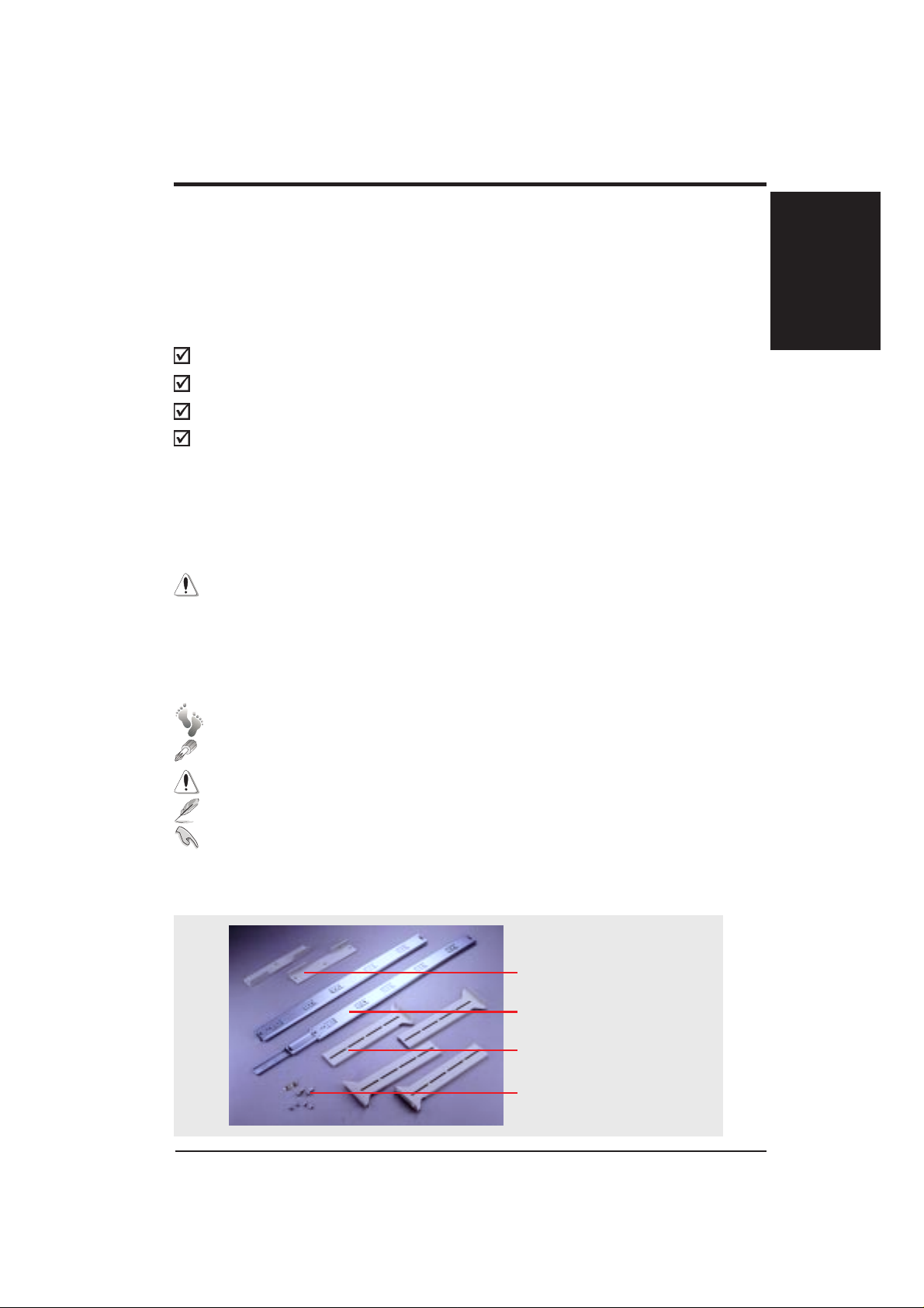
V. Components
The following is a picture of the checklist items.
Rack Mount Bracket
Three-section Rail
Rail Holder
Screw
ASUS AS-30 Rail Kit Installation Guide 9
Page 2
Installation Procedure
English
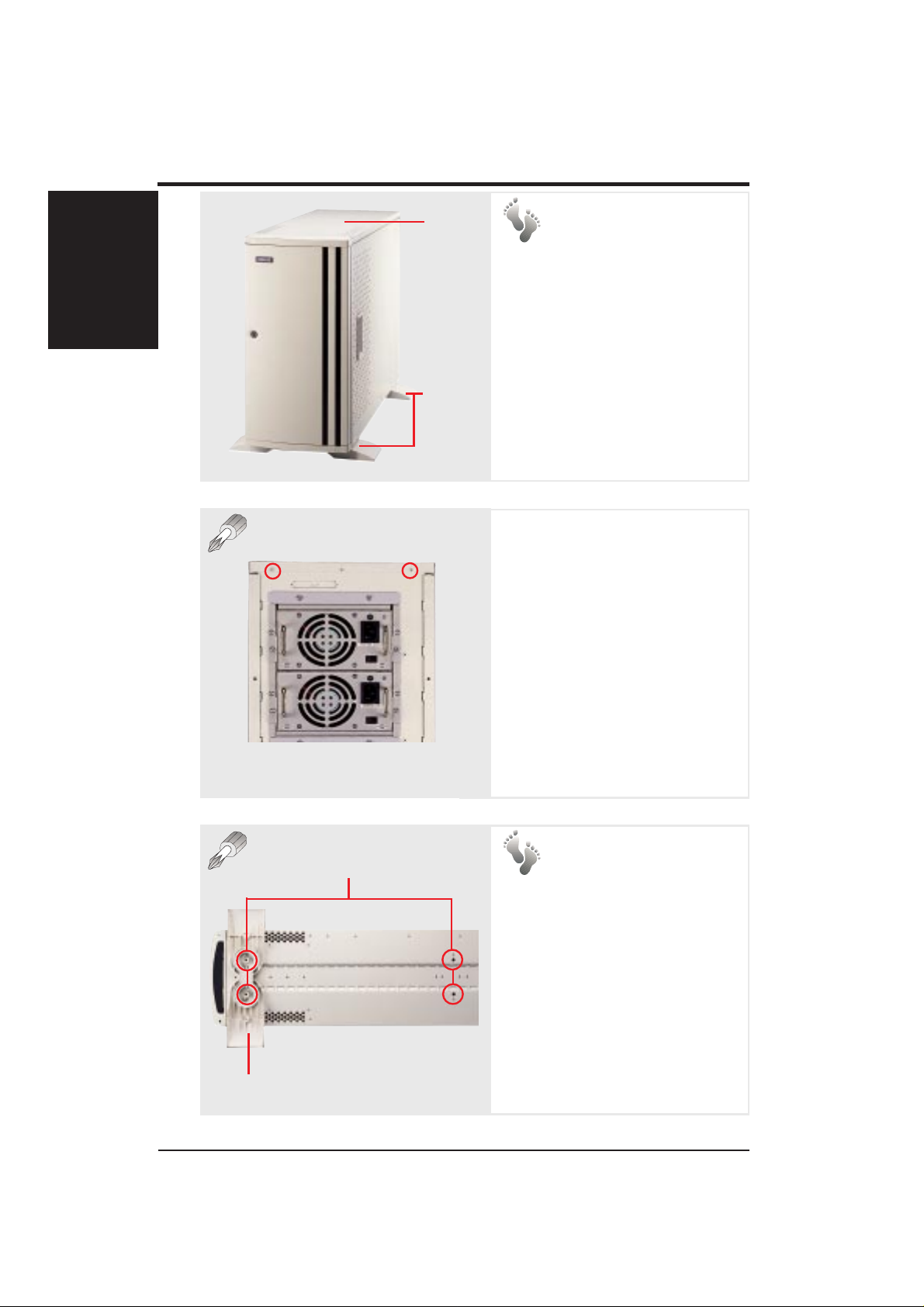
T op Panel
Chassis
Stabilizers
1. Remove the
Top Panel
Each rail has a removable section that must be attached to the
top or bottom of the chassis. Before doing so, remove the top
panel and chassis stabilizers.
Top Panel Screws
The top panel is secured by two
screws at the back of the chassis. To open the top panel, remove the screws with a screwdriver.
2. Remove the
Screw Holes
Chassis
Stabilizers
Remove the four screws that secure the chassis stabilizers.
Chassis
Stabilizer
10 ASUS AS-30 Rail Kit Installation Guide
Page 3
Installation Procedure
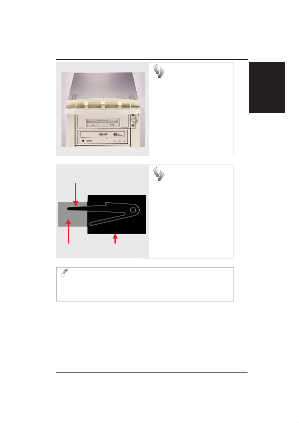
3. Remove the Top
Handle Cover
T op Handle Cover
Remove the top handle cover as
shown.
The top and bottom handles
make it easier to mount and pull
out the chassis. When using the
system independently, you may
want to install the top handle
cover for cosmetics.
English
Press the clamp to release the
first section of the rail.
4. Release the
First Section of
the Rail
The first (narrowest) section of the
rail should be attached to the chassis. The other two (middle and last)
sections, always held together, will
be used on the rack later.
To release the first section of the
First Section
NOTE: The clamp prevents the first section of the rail from sepa-
rating from the other two sections. To detach a well-mounted chassis
from the rack, you must release the first section of the rail by performing the above step as illustrated.
Middle Section
rail, slide it out until a clamp can
be seen. Press the clamp as shown.
ASUS AS-30 Rail Kit Installation Guide 11
Page 4

Installation Procedure
English
5. Install the Rails & Rack Mount Brackets
First Sections
of the Rails
Rack Mount
Brackets
1. Secure the rack mount brackets onto the chassis with three screws.
2. There are recessed tracks on the top and bottom of the chassis. Attach the
first section of the rail to the track and tighten the screws.
IMPORTANT: There are two models of chassis--10 and 24
holes, and two models of rails--15 and 21 holes. Refer to the chart on
the following page for screw matchings. You can fasten 5 screws on
the 10-hole chassis and 8 screws on the 24-hole chassis.
12 ASUS AS-30 Rail Kit Installation Guide
Page 5

Installation Procedure
Screw Hole Matching
As long as the first screw hole on the rail is matched with the proper
hole on the chassis, the rest of the holes will match. You may match the
holes by trial and error or by referring to the following chart.
NOTE: There are no differences between the two models other than
the number of screw holes.
Chassis Screw Holes
10 Holes (5 screws) 24 Holes (8 screws)
English
Rail
Screw
Holes
15Holes
21Holes
The 3rd rail hole matches
the 2nd chassis hole.
(not supported)
1
1
24-hole Chassis with the First Hole Labeled
The 1st rail hole matches
the 2nd chassis hole.
The 1st rail hole matches
the 1st chassis hole.
ASUS AS-30 Rail Kit Installation Guide 13
Page 6

English
Installation Procedure
6. Install the Rail Holders
Secure the rail holders onto the rack, using the top and bottom screw holes
as shown. Make sure the four rail holders are horizontally aligned when
attached to the rack.
NOTE: The rail holder is designed to connect the widest section
of the rail to the rack. The three holes on the rail holder are spaced
according to the EIA standard. The height from hole 1 to hole 3 is measured at one U (unit), which is 1.75” or 44.45mm.
14 ASUS AS-30 Rail Kit Installation Guide
Page 7

Fig. 7-B
Installation Procedure
7. Secure the Rails onto the Rail Holders
Fig. 7-A
English
A
Fig. 7-C
A
Secure the widest sections of the rail onto the rail holders as shown in Figure
7-A. Keep a distance of A between the front edge of the rail and the front
edge of the rail holder as shown in Figure 7-B. A equals the distance from the
narrowest section of the rail to the rack mount bracket. (See Figure 7-C.)
IMPORTANT: Distance A varies according to the positions of
the screw holes on your chassis and rails.
ASUS AS-30 Rail Kit Installation Guide 15
Page 8

English
Installation Procedure
8. Insert the Chassis onto the Rack
Slide the narrowest sections of the rail along with the chassis into the middle
sections of the rail.
Screw the rack mount brackets and the rack as shown.
9. Installation Finished
Secures the Bracket
onto the Rack
Secures the Rail
Holder onto the Rack
Secures the Bracket
onto the Rack
16 ASUS AS-30 Rail Kit Installation Guide
 Loading...