

Page 1

English
Power Supply
A/X series
Quick Reference
Page 2
® ®
®
Thank you for buying the ASUSThank you for buying the ASUS
Thank you for buying the ASUS
Thank you for buying the ASUSThank you for buying the ASUS
® ®
Power Supply!Power Supply!
Power Supply!
Power Supply!Power Supply!
English
The ASUS power supply combines the latest heat management and noise-reduction
technologies to ensure reliable and stable performance you can count on. The power
supply features over-power protection, over-voltage protection, and short-circuit
protection to prevent damage to the power supply and to your computer system.
Package contents
•
Power supply
•
AC power cord
•
Screws (4 pcs.)
•
Quick reference
If any of the above items is damaged or missing, contact your retailer.
Installing the power supply
1. For A-series, locate the voltage selector switch at the back of the power supply.
Set the power supply to the correct power voltage.
•
If the voltage supply in your area is 100~127V, set the switch to 115V.
•
If the voltage supply in your area is 200~240V, set the switch to 230V.
For models with full range AC input voltage, proceed to step 2.
2. Install the power supply into the chassis and secure it with four screws.
(Refer to the documentation that came with your system for specific
instructions.)
Power connectors
The connectors from the power supply are designed to fit in only one
orientation. Find the proper orientation and push down firmly until the
connectors fit completely.
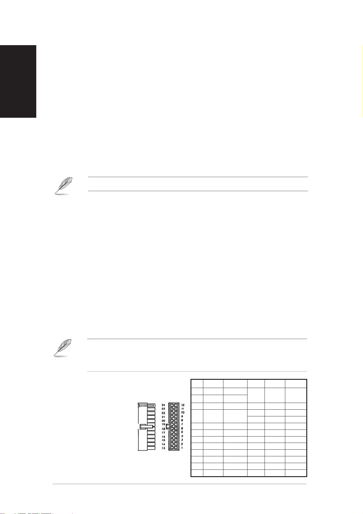
1.1.
ATX motherboard connectorATX motherboard connector
1.
ATX motherboard connector
1.1.
ATX motherboard connectorATX motherboard connector
(24-pin)(24-pin)
(24-pin)
(24-pin)(24-pin)
This connector is for
the main power
connector on the
motherboard.
PinPin
ColorColor
Pin
Color
PinPin
ColorColor
1 ORANGE +3.3V ORANGE +3.3V
2 ORANGE +3.3V 13 BROWN +3.3VS
3 BLACK GND 14 BLUE -12V
4 RED +5V 16 GREEN PS-ON
5 BLACK GND 17 BLACK GND
6 RED +5V 18 BLACK GND
7 BLACK GND 19 BLACK GND
8 GRAY PS 20 NC
9 PURPLE +5VSB 21 RED +5V
10 YELLOW +12V1 22 RED +5V
11 YELLOW +12V1 23 RED +5V
12 ORANGE +3.3V 24 BLACK GND
VoltageVoltage
Voltage
VoltageVoltage
PinPin
ColorColor
Pin
Color
PinPin
ColorColor
15 BLACK GND
VoltageVoltage
Voltage
VoltageVoltage
22
2
22
ASUS power supplyASUS power supply
ASUS power supply
ASUS power supplyASUS power supply
Page 3

2.2.
+12V connector (4-pin)+12V connector (4-pin)
2.
+12V connector (4-pin)
2.2.
+12V connector (4-pin)+12V connector (4-pin)
This connector is for the 4-pin
ATX +12V power connector on
the motherboard.
3.3.
Auxiliary connector (6-pin)Auxiliary connector (6-pin)
3.
Auxiliary connector (6-pin)
3.3.
Auxiliary connector (6-pin)Auxiliary connector (6-pin)
[optional][optional]
[optional]
[optional][optional]
This connector is for motherboards
that require extra power (250W or
more). This connector consists of
thicker wires for +3.3V and +5V
signals.
4.4.
Peripheral connector (4-pin)Peripheral connector (4-pin)
4.
Peripheral connector (4-pin)
4.4.
Peripheral connector (4-pin)Peripheral connector (4-pin)
This connector is for internal
hard disks, optical drives,
cooling devices, adapters, and
other peripheral devices.
VoltageVoltage
Voltage
VoltageVoltage
GND BLACK 1
GND BLACK 2
+12V YELLOW 3
+12V YELLOW 4
VoltageVoltage
Voltage
VoltageVoltage
GND BLACK 1
GND BLACK 2
GND BLACK 3
+3.3V ORANGE 4
+3.3V ORANGE 5
+5V RED 6
VoltageVoltage
Voltage
VoltageVoltage
+12V YELLOW 1
GND BLACK 2
GND BLACK 3
+5V RED 4
ColorColor
Color
ColorColor
ColorColor
Color
ColorColor
ColorColor
Color
ColorColor
PinPin
Pin
PinPin
PinPin
Pin
PinPin
PinPin
Pin
PinPin
English
5.5.
Floppy disk connector (4-pin)Floppy disk connector (4-pin)
5.
Floppy disk connector (4-pin)
5.5.
Floppy disk connector (4-pin)Floppy disk connector (4-pin)
This connector is for a 3.5” floppy
disk drive.
6.6.
Serial ATA (SATA) connectorSerial ATA (SATA) connector
6.
Serial ATA (SATA) connector
6.6.
Serial ATA (SATA) connectorSerial ATA (SATA) connector
(5-pin) [optional](5-pin) [optional]
(5-pin) [optional]
(5-pin) [optional](5-pin) [optional]
This connector is for Serial
ATA devices.
7.7.
PCI Express™ connectorPCI Express™ connector
7.
PCI Express™ connector
7.7.
PCI Express™ connectorPCI Express™ connector
(6-pin)(6-pin)
(6-pin)
(6-pin)(6-pin)
This connector is for PCI
Express high-end graphics
add-in cards.
VoltageVoltage
Voltage
VoltageVoltage
+5V RED 1
GND BLACK 2
GND BLACK 3
+12V YELLOW 4
VoltageVoltage
Voltage
VoltageVoltage
+3.3V ORANGE 1
GND BLACK 2
+5V RED 3
GND BLACK 4
+12V YELLOW 5
VoltageVoltage
Voltage
VoltageVoltage
+12V YELLOW 1
+12V YELLOW 2
+12V YELLOW 3
GND BLACK 4
SENSE BLACK 5
GND BLACK 6
ColorColor
Color
ColorColor
ColorColor
Color
ColorColor
ColorColor
Color
ColorColor
PinPin
Pin
PinPin
PinPin
Pin
PinPin
PinPin
Pin
PinPin
ASUS power supplyASUS power supply
ASUS power supply
ASUS power supplyASUS power supply
33
3
33
Page 4

Protection features
1.1.
Over-power protectionOver-power protection
1.
Over-power protection
1.1.
Over-power protectionOver-power protection
English
The power supply shuts down and latches off when output power is within
120 ~ 150 percent of rated DC output.
2.2.
Over-voltage protectionOver-voltage protection
2.
Over-voltage protection
2.2.
Over-voltage protectionOver-voltage protection
No single point fault causes a sustained over-voltage condition on any or all
outputs. The power supply provides latch-mode over-voltage protection as
defined in the following table.
OutputOutput
Output
OutputOutput
+12V1DC 13.4 15.0 15.6 Volts
+12V2DC 13.4 15.0 15.6 Volts
+5VDC 5.74 6.3 7.0 Volts
+3.3VDC 3.76 4.2 4.3 Volts
3. Short-circuit protection3. Short-circuit protection
3. Short-circuit protection
3. Short-circuit protection3. Short-circuit protection
MinimumMinimum
Minimum
MinimumMinimum
NominalNominal
Nominal
NominalNominal
MaximumMaximum
Maximum
MaximumMaximum
UnitUnit
Unit
UnitUnit
The power supply can withstand a continuous short-circuit to the output without
damaging or overstressing the unit. The power supply shuts down and latches
off for shorting the +3.3V, +5V, +12V1, +12V2, or -12V rails to return. Shorts
between main output rails and +5VSB do not cause any damage to the power
supply.
4. Over-current protection4. Over-current protection
4. Over-current protection
4. Over-current protection4. Over-current protection
Overload currents applied to each tested output rail will cause the output to trip
before reaching or exceeding 240 VA. For testing purposes, the overload
currents should be ramped at a minimum rate of 10 A/s starting from full load.
Warning!
To reduce the risk of fire, electric shock, body injury, or damage to the power supply
and/or your computer system, take the following safety precautions:
•
Never open or dismantle the power supply!
•
Do not remove the power supply while the system is on.
•
Do not unplug the AC power cord while the system is on.
•
Do not put the power supply where it can get wet.
Troubleshooting
If the power supply fails to function properly, do the following:
•
Check if the AC power cord is plugged firmly.
•
Check if the extension power cord is switched on.
•
Check if the voltage switch is set to the appropriate position (115V or 230V).
•
Check if the main power connector is firmly plugged into the socket.
•
Disconnect the power cord to reset the power supply. Reconnect after 30
seconds or so.
For more information, visit the ASUS website at www.asus.com.For more information, visit the ASUS website at www.asus.com.
For more information, visit the ASUS website at www.asus.com.
For more information, visit the ASUS website at www.asus.com.For more information, visit the ASUS website at www.asus.com.
44
4
44
ASUS power supplyASUS power supply
ASUS power supply
ASUS power supplyASUS power supply
 Loading...