

Page 1

MAXIMUS VI
HERO
Motherboard
Page 2

E8459
Revised Edition V2
June 2013
Copyright © 2013 ASUSTeK COMPUTER INC. All Rights Reserved.
No part of this manual, including the products and software described in it, may be reproduced,
transmitted, transcribed, stored in a retrieval system, or translated into any language in any form or by any
means, except documentation kept by the purchaser for backup purposes, without the express written
permission of ASUSTeK COMPUTER INC. (“ASUS”).
Product warranty or service will not be extended if: (1) the product is repaired, modied or altered, unless
such repair, modication of alteration is authorized in writing by ASUS; or (2) the serial number of the
product is defaced or missing.
ASUS PROVIDES THIS MANUAL “AS IS” WITHOUT WARRANTY OF ANY KIND, EITHER EXPRESS
OR IMPLIED, INCLUDING BUT NOT LIMITED TO THE IMPLIED WARRANTIES OR CONDITIONS OF
MERCHANTABILITY OR FITNESS FOR A PARTICULAR PURPOSE. IN NO EVENT SHALL ASUS, ITS
DIRECTORS, OFFICERS, EMPLOYEES OR AGENTS BE LIABLE FOR ANY INDIRECT, SPECIAL,
INCIDENTAL, OR CONSEQUENTIAL DAMAGES (INCLUDING DAMAGES FOR LOSS OF PROFITS,
LOSS OF BUSINESS, LOSS OF USE OR DATA, INTERRUPTION OF BUSINESS AND THE LIKE),
EVEN IF ASUS HAS BEEN ADVISED OF THE POSSIBILITY OF SUCH DAMAGES ARISING FROM ANY
DEFECT OR ERROR IN THIS MANUAL OR PRODUCT.
SPECIFICATIONS AND INFORMATION CONTAINED IN THIS MANUAL ARE FURNISHED FOR
INFORMATIONAL USE ONLY, AND ARE SUBJECT TO CHANGE AT ANY TIME WITHOUT NOTICE,
AND SHOULD NOT BE CONSTRUED AS A COMMITMENT BY ASUS. ASUS ASSUMES NO
RESPONSIBILITY OR LIABILITY FOR ANY ERRORS OR INACCURACIES THAT MAY APPEAR IN THIS
MANUAL, INCLUDING THE PRODUCTS AND SOFTWARE DESCRIBED IN IT.
Products and corporate names appearing in this manual may or may not be registered trademarks or
copyrights of their respective companies, and are used only for identication or explanation and to the
owners’ benet, without intent to infringe.
Offer to Provide Source Code of Certain Software
This product contains copyrighted software that is licensed under the General Public License (“GPL”),
under the Lesser General Public License Version (“LGPL”) and/or other Free Open Source Software
Licenses. Such software in this product is distributed without any warranty to the extent permitted by the
applicable law. Copies of these licenses are included in this product.
Where the applicable license entitles you to the source code of such software and/or other additional data,
you may obtain it for a period of three years after our last shipment of the product, either
(1) for free by downloading it from http://support.asus.com/download
or
(2) for the cost of reproduction and shipment, which is dependent on the preferred carrier and the location
where you want to have it shipped to, by sending a request to:
ASUSTeK Computer Inc.
Legal Compliance Dept.
15 Li Te Rd.,
Beitou, Taipei 112
Taiwan
In your request please provide the name, model number and version, as stated in the About Box of the
product for which you wish to obtain the corresponding source code and your contact details so that we
can coordinate the terms and cost of shipment with you.
The source code will be distributed WITHOUT ANY WARRANTY and licensed under the same license as
the corresponding binary/object code.
This offer is valid to anyone in receipt of this information.
ASUSTeK is eager to duly provide complete source code as required under various Free Open Source
Software licenses. If however you encounter any problems in obtaining the full corresponding source
code we would be much obliged if you give us a notication to the email address gpl@asus.com, stating
the product and describing the problem (please DO NOT send large attachments such as source code
archives, etc. to this email address).
ii
Page 3

Contents
Safety information ...................................................................................................... vi
About this guide ........................................................................................................ vii
MAXIMUS VI HERO specications summary .......................................................... ix
Package contents ..................................................................................................... xiii
Installation tools and components ......................................................................... xiv
Chapter 1: Product Introduction
1.1 Special features..........................................................................................1-1
1.1.1 Product highlights........................................................................1-1
1.1.2 ROG Gaming Features ............................................................... 1-2
1.1.3 ROG Exclusive Features.............................................................1-3
1.1.4 ASUS Special Features ..............................................................1-3
1.1.5 ROG rich bundled software .........................................................1-4
1.2 Motherboard overview ............................................................................... 1-5
1.2.1 Before you proceed .....................................................................1-5
1.2.2 Motherboard layout ..................................................................... 1-6
1.2.3 Central Processing Unit (CPU) ...................................................1-8
1.2.4 System memory .......................................................................... 1-9
1.2.5 Expansion slots ......................................................................... 1-23
1.2.6 Onboard buttons .......................................................................1-25
1.2.7 Jumper ...................................................................................... 1-28
1.2.8 Onboard LEDs ..........................................................................1-29
1.2.9 Internal connectors....................................................................1-38
Chapter 2: Basic Installation
2.1 Building your PC system...........................................................................2-1
2.1.1 Motherboard installation ..............................................................2-1
2.1.2 CPU installation...........................................................................2-3
2.1.3 CPU heatsink and fan assembly installation ............................... 2-4
2.1.4 DIMM installation.........................................................................2-6
2.1.5 ATX Power connection ................................................................ 2-7
2.1.6 SATA device connection ..............................................................2-8
2.1.7 Front I/O Connector ....................................................................2-9
2.1.8 Expansion Card installation.......................................................2-10
2.2 BIOS update utility ................................................................................... 2-11
2.3 Motherboard rear and audio connections .............................................2-12
2.3.1 Rear I/O connection .................................................................. 2-12
2.3.2 Audio I/O connections ............................................................... 2-13
2.4 Starting up for the rst time .................................................................... 2-17
2.5 Turning off the computer ......................................................................... 2-17
iii
Page 4

Chapter 3: BIOS setup
3.1 Knowing BIOS ............................................................................................3-1
3.2 BIOS setup program ..................................................................................3-2
3.2.1 EZ Mode......................................................................................3-3
3.2.2 Advanced Mode .......................................................................... 3-4
3.3 My Favorites ...............................................................................................3-6
3.4 Extreme Tweaker menu ............................................................................. 3-7
3.5 Main menu ................................................................................................3-23
3.6 Advanced menu .......................................................................................3-25
3.6.1 CPU Conguration .................................................................... 3-26
3.6.2 PCH Conguration .................................................................... 3-28
3.6.3 SATA Conguration ................................................................... 3-30
3.6.4 System Agent Conguration......................................................3-31
3.6.5 USB Conguration ....................................................................3-33
3.6.6 Platform Misc Conguration ...................................................... 3-34
3.6.7 Onboard Devices Conguration ................................................ 3-35
3.6.8 APM ..........................................................................................3-37
3.6.9 Network Stack ........................................................................... 3-38
3.6.10 ROG Effects .............................................................................. 3-38
3.7 Monitor menu ...........................................................................................3-39
3.8 Boot menu ................................................................................................3-42
3.9 Tools menu ............................................................................................... 3-47
3.9.1 ASUS EZ Flash 2 Utility ............................................................ 3-47
3.9.2 ROG Secure Erase ................................................................... 3-47
3.9.3 ASUS O.C. Prole ..................................................................... 3-49
3.9.4 ASUS SPD Information ............................................................. 3-50
3.9.5 ROG OC Panel H-Key Congure .............................................. 3-50
3.10 Exit menu ..................................................................................................3-52
3.11 Updating BIOS .......................................................................................... 3-53
3.11.1 EZ Update ................................................................................. 3-53
3.11.2 ASUS EZ Flash 2 ...................................................................... 3-54
3.11.3 ASUS CrashFree BIOS 3 .......................................................... 3-55
3.11.4 ASUS BIOS Updater ................................................................. 3-56
iv
Page 5

Chapter 4: Software support
4.1 Installing an operating system .................................................................4-1
4.2 Support DVD information .......................................................................... 4-1
4.2.1 Running the support DVD ........................................................... 4-1
4.2.2 Obtaining the software manuals..................................................4-2
4.3 Software information .................................................................................4-3
4.4 AI Suite 3 ..................................................................................................... 4-3
4.4.1 Dual Intelligent Processors 4 with 4-Way Optimization ............... 4-6
4.4.2 EZ Update ................................................................................. 4-13
4.4.3 USB 3.0 Boost...........................................................................4-14
4.4.4 System Information ................................................................... 4-15
4.4.5 USB BIOS Flashback ................................................................ 4-17
4.4.6 USB Charger+ ........................................................................... 4-19
4.4.7 Audio congurations..................................................................4-20
4.5 MemTweakIt .............................................................................................. 4-21
4.6 RAMDisk ...................................................................................................4-23
4.7 Sonic Radar ..............................................................................................4-26
4.7.1 Main menu ...............................................................................4-26
4.7.2 Game presets and Radar Selection ......................................... 4-28
4.7.3 Advanced Settings ................................................................... 4-29
4.8 Perfect Voice .............................................................................................4-31
Chapter 5: RAID support
5.1 RAID congurations ..................................................................................5-1
5.1.1 RAID denitions ..........................................................................5-1
5.1.2 Installing Serial ATA hard disks ...................................................5-2
5.1.3 Setting the RAID item in BIOS .................................................... 5-2
5.1.4 Intel® Rapid Storage Technology Option ROM utility ..................5-3
5.2 Creating a RAID driver disk.......................................................................5-7
5.2.1 Creating a RAID driver disk without entering the OS .................. 5-7
5.2.2 Creating a RAID driver disk in Windows
5.2.3 Installing the RAID driver during Windows® OS installation ........ 5-8
® .................................................................5-8
Appendices
Notices .................................................................................................................... A-1
ASUS contact information ...................................................................................... A-4
v
Page 6

Safety information
Electrical safety
To prevent electrical shock hazard, disconnect the power cable from the electrical outlet
•
before relocating the system.
When adding or removing devices to or from the system, ensure that the power cables
•
for the devices are unplugged before the signal cables are connected. If possible,
disconnect all power cables from the existing system before you add a device.
Before connecting or removing signal cables from the motherboard, ensure that all
•
power cables are unplugged.
Seek professional assistance before using an adapter or extension cord. These devices
•
could interrupt the grounding circuit.
Ensure that your power supply is set to the correct voltage in your area. If you are not
•
sure about the voltage of the electrical outlet you are using, contact your local power
company.
If the power supply is broken, do not try to x it by yourself. Contact a qualied service
•
technician or your retailer.
Operation safety
Before installing the motherboard and adding devices on it, carefully read all the manuals
•
that came with the package.
Before using the product, ensure all cables are correctly connected and the power
•
cables are not damaged. If you detect any damage, contact your dealer immediately.
To avoid short circuits, keep paper clips, screws, and staples away from connectors,
•
slots, sockets and circuitry.
Avoid dust, humidity, and temperature extremes. Do not place the product in any area
•
where it may become wet.
Place the product on a stable surface.
•
If you encounter technical problems with the product, contact a qualied service
•
technician or your retailer.
vi
Page 7

About this guide
This user guide contains the information you need when installing and conguring the
motherboard.
How this guide is organized
This guide contains the following parts:
• Chapter 1: Product introduction
This chapter describes the features of the motherboard and the new technology it
supports. It includes description of the switches, jumpers, and connectors on the
motherboard.
• Chapter 2: Basic Installation
This chapter lists the hardware setup procedures that you have to perform when
installing system components.
• Chapter 3: BIOS setup
This chapter tells how to change system settings through the BIOS Setup menus.
Detailed descriptions of the BIOS parameters are also provided.
• Chapter 4: Software support
This chapter describes the contents of the support DVD that comes with the
motherboard package and the software.
• Chapter 5: RAID support
This chapter describes the RAID congurations.
Where to nd more information
Refer to the following sources for additional information and for product and software
updates.
1. ASUS website
The ASUS website (www.asus.com) provides updated information on ASUS hardware
and software products.
2. Optional documentation
Your product package may include optional documentation, such as warranty yers,
that may have been added by your dealer. These documents are not part of the
standard package.
vii
Page 8

Conventions used in this guide
To ensure that you perform certain tasks properly, take note of the following symbols used
throughout this manual.
DANGER/WARNING: Information to prevent injury to yourself when trying to
complete a task.
CAUTION: Information to prevent damage to the components when trying to
complete a task
IMPORTANT: Instructions that you MUST follow to complete a task. .
NOTE: Tips and additional information to help you complete a task.
Typography
Bold text Indicates a menu or an item to select.
Italics
<Key> Keys enclosed in the less-than and greater-than sign
<Key1> + <Key2> + <Key3> If you must press two or more keys simultaneously, the key
Used to emphasize a word or a phrase.
means that you must press the enclosed key.
Example: <Enter> means that you must press the Enter or
Return key.
names are linked with a plus sign (+).
viii
Page 9
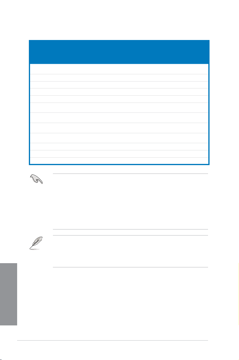
MAXIMUS VI HERO specications summary
LGA1150 socket for the 4th Generation Intel® Core™ i7/Intel®
Core™i5/Intel® Core™ i3, Pentium®, and Celeron® processors
Supports 22nm CPU
CPU
Chipset
Memory
Expansion slots
VGA
Multi-GPU support Support NVIDIA® SLI® Technology / AMD CrossFireX™ Technology
Storage
Supports Intel® Turbo Boost Technology 2.0*
* The Intel® Turbo Boost Technology 2.0 support depends on the CPU
types.
** Refer to www.asus.com for Intel CPU support list
Intel® Z87 Express Chipset
Dual channel memory architecture
4 x DIMM, max. 32GB, DDR3 2800 (O.C.) / 2666 (O.C.) / 2600
(O.C.) / 2500 (O.C.) / 2400 (O.C.) / 2200 (O.C.) / 2133 (O.C.) / 2000
(O.C.) / 1866 (O.C.) / 1800 (O.C.) / 1600 / 1333 MHz, non-ECC,
un-buffered memory
Supports Intel® Extreme Memory Prole (XMP)
* Hyper DIMM support is subject to the physical characteristics of
individual CPUs.
** Please refer to Memory QVL (Qualied Vendors List) for details.
2 x PCI Express 3.0/2.0 x16 slots (Red, single at x16 or dual at
x8/x8 mode)
1 x PCI Express 2.0 x16 slot (Black, max. at x4 mode)*(Black, max. at x4 mode)*
3x PCI Express 2.0 x1 slot**
* The PCIe 2.0 x16 slot (PCIEX4_3) shares bandwidth with PCIe 2.0 x1
slots. The default setting is x1 mode.
** The PCIe 2.0 x1 slots (PCIEX1_1, PCIEX1_2, and PCIEX1_3) are
disabled when the PCIe 2.0 x16 slot (PCIEX4_3) operates under x4
speed.
Integrated Intel® HD Graphics Processor
HDMI with max. resolution of 4096 x 2160 @ 24Hz / 2560 x 1600
@ 60Hz
Intel® InTru™ 3D, Intel 3D, Intel® Quick Sync Video, Intel® Clear Video HD
Technology, and Intel® Insider™Insider™
Intel® Z87 Express Chipset:
6 x SATA 6 Gb/s ports*
- Intel® Rapid Storage Technology 12 supports RAID 0, 1, 5, and
10
- Intel® Smart Response Technology, Intel® Rapid Start
Technology, and Intel® Smart Connect Technology*
ASMedia
2 x SATA 6 Gb/s ports**
* The supported functions depend on the CPU installed.
** These SATA ports are for data hard drives only. ATAPI devices are not
®
SATA 6Gb/s controller:
supported.
(continued on the next page)
ix
Page 10

LAN 1 x Intel® I217-V Gigabit LAN Controller
ROG SupremeFX Audio 8-Channel High Denition
Audio
- SupremeFX Shielding Technology
- ELNA® Premium Audio Capacitors
- Content Protection for Full Rate lossless DVD Audio, Blu-ray
Audio
DVD, and HD-DVD audio content playback
- Jack-detection, Multi-streaming, Front Panel Jack-retasking
- Optical S/PDIF out port at back panel
Audio Feature:
- Sonic Radar
- DTS Connect
Intel® Z87 Express Chipset
6 x USB 3.0 ports (4 ports at back panel [blue], 2 ports at mid-board
[red]*)
8 x USB 2.0 ports (4 ports at back panel, for ROG Connect; 4 ports
USB
Back I/O Ports
at mid-board**)
* Supports ASUS USB 3.0 Boost, UASP standard on the Intel® native
USB 3.0 is only supported under Windows® 8.
** 2 x USB2.0 ports at mid-board shares with ROG extension (ROG_EXT)
port.
1 xPS/2 keyboard/mouse combo port
4 x USB 2.0 ports
1 x USB BIOS Flashback button
1 x Optical S/PDIF out
1 x HDMI port
4 x USB 3.0 ports [blue]
1 x LAN (RJ45) port
6 x Audio jacks
(continued on the next page)
x
Page 11

ROG Exclusive Features
Special Features
Extreme Engine Digi+ III
- Full digital 8+2 phase CPU/DRAM power
- NexFETTM Power Block MOSFET
- 60A BlackWing Chokes
- 10K Black Metallic Capacitors
ROG GameFirst II
ROG RAMDisk
CPU Level Up
UEFI BIOS features
- Extreme Tweaker
- Tweaker’s Paradise
- ROG SSD Secure Erase
- BIOS Print
- GPU.DIMM Post
- O.C. Prole
- ROG Pulse
ASUS Dual Intelligent Processors 4
- 4-way Optimization Tuning Key, consolidating DIGI+ Power
Control, TPU, EPU, and Fan Xpert 2
ASUS Exclusive Features
- AI Suite 3
- USB 3.0 Boost
- USB Charger+
- AI Charger
- Disk Unlocker
ASUS EZ DIY
- USB BIOS Flashback
- ASUS CrashFree BIOS 3
- ASUS EZ Flash 2
- ASUS C.P.R. (CPU Parameter Recall)
ASUS Q-Design
- ASUS Q-Code
- ASUS Q-Shield
- ASUS Q-Connector
- ASUS Q-LED (CPU, DRAM, VGA, Boot Device LED)
- ASUS Q-Slot
- ASUS Q-DIMM
(continued on the next page)
xi
Page 12

1 x USB 3.0 connector (supports additional 2 USB 3.0 ports)
2 x USB 2.0 connectors (support additional 4USB 2.0 ports, 1
connector shares with ROG_EXT header)
1 x ROG Extension (ROG_EXT) header
8 x SATA 6Gb/s connectors
1 x 4-pin CPU fan connector
1 x 4-pin CPU optional fan connector
3 x 4-pin Chassis fan connectors
1 x 24-pin EATX power connector
Internal Connectors
BIOS Features
Manageability WfM2.0, DMI2.0, WOL by PME, PXE
Software
Form Factor ATX Form Factor, 12” x 9.6” (30.5cm x 24.4cm)
1 x 8-pin EATX 12V Power connector
1 x Clear CMOS jumper
1 x Power-on button
1 x Reset button
1 x MemOK! button
1 x Directkey button
1 x DRCT (DirectKey) header
1 x S/PDIF out header
1 x Front panel audio connector (AAFP)
1 x System panel connector
1 x TPM connector
64 Mb UEFI AMI BIOS, PnP, DMI 2.0, WfM 2.0, SM BIOS 2.5, ACPI
2.0a, Multi-language BIOS
Drivers
ROG GameFirst II
ROG RAMDisk
ROG CPU-Z
ROG Mem TweakIt
Kaspersky® Anti-Virus
DAEMON Tools Pro Standard
ASUS WebStorage
ASUS Utilities
Specications are subject to change without notice.
xii
Page 13

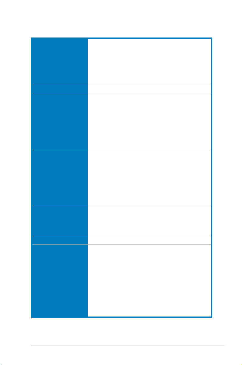
Package contents
Check your motherboard package for the following items.
Motherboard ROG MAXIMUS VI HERO
Cables 3 x 2-in-1 SATA 6 Gb/s cables
1 x SLI® bridge
Accessories I/O Shield
1 x 12-in-1 ROG cable label
1 x 2-in-1 Q-Connector kit
1 x ROG Door Hanger
Application DVD ROG motherboard support DVD
Documentation User guide
If any of the above items is damaged or missing, contact your retailer.
xiii
Page 14
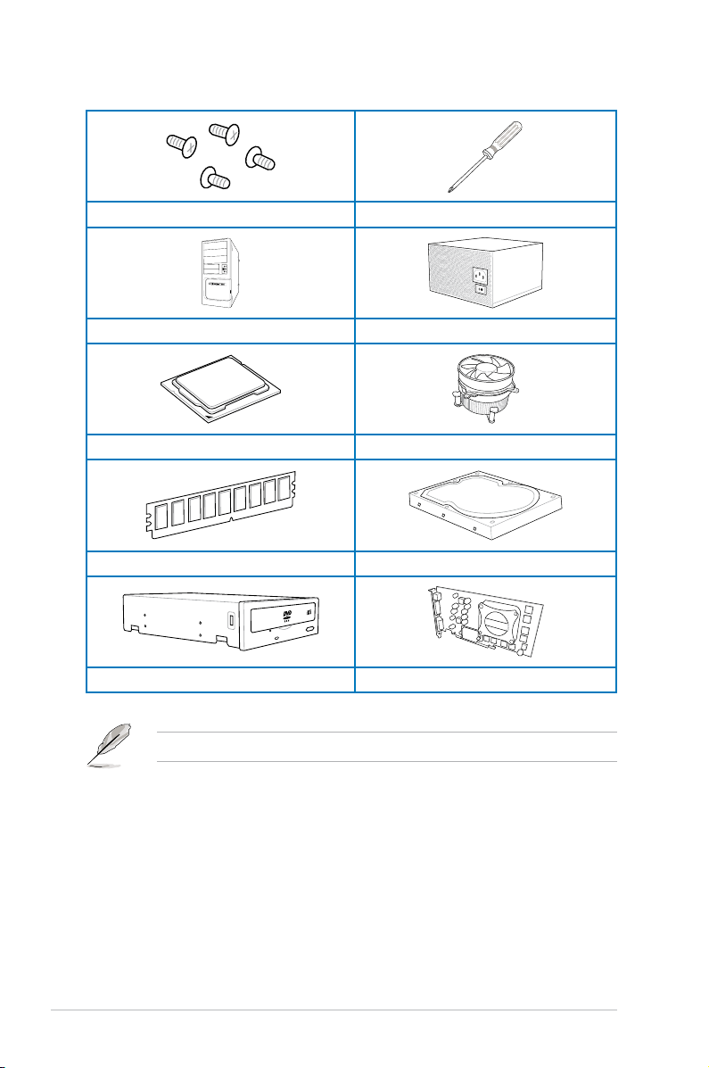
Installation tools and components
1 bag of screws Philips (cross) screwdriver
PC chassis Power supply unit
Intel LGA 1150 CPU Intel LGA 1150 compatible CPU Fan
DDR3 DIMM SATA hard disk drive
xiv
SATA optical disc drive (optional) Graphics card (optional)
The tools and components in the table above are not included in the motherboard package.
Page 15

Chapter 1: Product Introduction
Product introduction
1
1.1 Special features
1.1.1 Product highlights
Republic of Gamers
The Republic of Gamers offers you the best of the best. We offer the best hardware
engineering, the fastest performance, the most innovative ideas, and we welcome the best
gamers to join in. In the Republic of Gamers, mercy rules are only for the weak, and bragging
rights means everything. We believe in making statements and we excel in competitions.
If your character matches our trait, then join the elite Republic of Gamers and make your
presence felt.
LGA1150 socket for 4th Generation Intel® Core™ i7 / Intel
®
Intel
Core™ i3, Pentium® and Celeron® Processors
This motherboard supports 4th generation Intel® Core™ i7/ Intel® Core™ i5/ Intel® Core™
i3, Pentium® and Celeron® processors in the LGA1150 package. It provides great graphics
and system performance with its GPU, dual-channel DDR3 memory slots, and PCI Express
2.0/3.0 expansion slots.
Intel® Z87 Express Chipset
Intel® Z87 Express Chipset is a single-chipset that supports the LGA1150 socket 4th
generation Intel® Core™ i7/ Intel® Core™ i5/ Intel® Core™ i3, Pentium® and Celeron®
processors. It utilizes the serial point-to-point links, which increases bandwidth and enhances
the system’s performance. It natively supports up to six USB 3.0 ports for up to ten times
faster transfer rate than USB 2.0, and enables the iGPU function for Intel® integrated graphics
performance.
PCI Express® 3.0
PCI Express® 3.0 (PCIe 3.0) is the latest PCI Express bus standard with improved encoding
schemes that provide twice the performance of current PCIe 2.0. Total bandwidth for a x16
link reaches a maximum of 32GB/s, double the 16GB/s of PCIe 2.0 (in x16 mode). As such,
PCIe 3.0 provides users unprecedented data speeds, combined with the convenience and
seamless transition offered by complete backward compatibility with PCIe 1.0 and PCIe
2.0 devices. PCIe 3.0 will become a must-have feature for users who wish to improve and
optimize graphic performance, as well as have the latest technology available to them.
SLI®/CrossFire™ On-Demand
This motherboard features a unique PCIe 3.0 bridge chip to support multi-GPU SLI®/
CrossFireX™ graphics cards for an unrivaled gaming performance. With the Intel
platform to optimize the PCIe allocation of multiple GPUs, it supports up to 4-WAY GPU SLI
or CrossFireX™ conguration..
®
Core™ i5 /
®
Z87
®
Chapter 1
ASUS MAXIMUS VI HERO
1-1
Page 16

1.1.2 ROG Gaming Features
SupremeFX
The re-engineered ROG-exclusive SupremeFX audio technology features an onboard
8-channel high-denition sound of true audophile-grade performance that is equal in power,
clarity, and range to dedicated sound cards. Its unique Red Line Shielding and special
metallic cover provides pristine sound and a highly attractive look for the motherboard
that is in keeping with the ROG style. The Japan-made premium ELNA capacitor ensures
warm natural sound with exceptional clarity for all your gaming and multimedia activities.
SupremeFX revolutionizes the way you hear games, movies, music, and even other people
via chat - letting you rule and discover a totally whole new dimension of superior audio.
Sonic Radar
Sonic Radar, an audio software designed for First Person Shooting (FPS) games, shows the
precise direction and intensity of where a sound is coming from. In-game sound including
gunshots, footprints, voice call-outs, or even a ticking bomb, is visualized as radar signals
on the Sonic Radar display, providing you the advantage to know potential threats and avoid
sneaky surprises.
GameFirst II
ASUS GameFirst II, with cFOS Trafc Shaping technology, provides a powerful and user-
friendly network control to easily frag your gaming system. Featuring the EZ Mode for
beginners’ setup and Advanced Mode for professionals’ tweaking, your frags comes rst.
Intel Gigabit LAN
The LAN solution from Intel has been long known to have a better throughput, lower CPU
utilization as well as better stability. With the Intel Gigabit LAN solutions onboard, the
ultimate network experience can therefore be delivered to its users like never before.
Chapter 1
1-2
Chapter 1: Product introduction
Page 17

1.1.3 ROG Exclusive Features
Extreme Engine Digi+ III
Extreme Engine Digi+ III offers you a hardcore power delivery for a challenging and extreme
gaming enjoyment. It utilizes the best components such as NexFET™ Power Block
MOSFETs, BlackWing chokes with special n design, and super-premium 10K black metallic
solid state capacitors. The NexFET™ Power Block MOSFETs combine great durability and
up to 90% efciency under normal operation. BlackWing chokes can handle as much as
60A of power, which is twice that of generic chokes. The special n design, with its highly
conductive and efcient gold-treated coating, results in 3-5oC lower choke temperatures for
added stability and ensures minimal-loss power delivery. Super-premium 10K Black Metallic
solid state capacitors are forged for overclocking and the most extreme demands, lasting up
to ve times longer than generic capacitors with 20% wider temperature tolerance.
RAMDisk
RAMDisk is an innovative program that reserves a part of your system’s memory and turns
it into a high-speed virtual drive where you can store cache les and game apps for instant
access. By optimizing your SSD, RAMDisk allows you to automatically backup, update, and
restore les.
NOTE: RAMDisk only supports 64-bit operating systems.
CPU Level Up
With ROG’s CPU Level Up, overclocking has never been so easy, or cost-free. Simply select
the processor that you want to overclock to, and the motherboard will do the rest.
1.1.4 ASUS Special Features
AI Suite 3
With its user-friendly interface, ASUS AI Suite 3 consolidates all the exclusive ASUS
features into one simple-to-use software package. It allows you to supervise fan speed
control, voltage and sensor readings. This all-in-one software offers diverse and ease to use
functions, with no need to switch back and forth between different utilities.
USB BIOS FlashBack
USB BIOS Flashback offers a hassle-free updating solution for your ultimate convenience.
Simply install a USB storage device containing the BIOS le, press the BIOS Flashback
button for three seconds, and the UEFI BIOS is automatically updated even without entering
the existing the BIOS or operating system. It also allows you to regularly check for UEFI
BIOS updates, and download the latest BIOS automatically.
ASUS MAXIMUS VI HERO
Chapter 1
1-3
Page 18

1.1.5 ROG rich bundled software
Kaspersky® Anti-Virus
Kaspersky® Anti-Virus Personal offers premium antivirus protection for individual users and
home ofces. It is based on advanced antivirus technologies. The product incorporates the
Kaspersky® Anti-Virus engine, which is renowned for malicious program detection rates that
are among the industry’s highest.
DAEMON Tools Pro Standard
DAEMON Tools Pro offers essential functionality to backup CD, DVD and Blu-ray discs. It
converts optical media into virtual discs and emulates devices to work with the virtual copies.
DAEMON Tools Pro organizes data, music, video, and photo collections on a PC, notebook,
or netbook.
ROG CPU-Z
ROG CPU-Z is a customized ROG version utitity authorized by Intel’s CPU Indentication
(CPUID) that allows you to gather information of the main devices of your system. It
gives you the information and status of your CPU, motherboard, memory, and the whole
component. Use the ROG look of reporting your system’s current information with ROG
CPU-Z.
MemTweakIt
MemTweakIt is a DRAM efciency tool that allows you to read DRAM timings and allows you
to post and share your DRAM conguration scores to the ROG website.
DTS Connect
To get the most out of your audio entertainment across all formats and quality levels, DTS
Connect combines two enabling technologies, DTS Neo:PC™ upmixes stereo sources (CDs,
MP3s, WMAs, internet radio) into as many as 7.1 channels of incredible surround sound.
Consumers can connect their PC to a home theater system. DTS Interactive is capable of
performing mult-channel encoding of DTS bitstreams on personal computers, and sending
encoded bitstreams out of a digital audio connection (such as S/PDIF or HDMI) designed to
deliver audio to an external decoder.
Chapter 1
1-4
Chapter 1: Product introduction
Page 19

1.2 Motherboard overview
1.2.1 Before you proceed
Take note of the following precautions before you install motherboard components or change
any motherboard settings.
• Unplug the power cord from the wall socket before touching any component.
• Before handling components, use a grounded wrist strap or touch a safely groundedBefore handling components, use a grounded wrist strap or touch a safely grounded
object or a metal object, such as the power supply case, to avoid damaging them due
to static electricity.
• Hold components by the edges to avoid touching the ICs on them.Hold components by the edges to avoid touching the ICs on them.
• Whenever you uninstall any component, place it on a grounded antistatic pad or in the
bag that came with the component.
• Before you install or remove any component, ensure that the ATX power supply is
switched off or the power cord is detached from the power supply. Failure to do so
may cause severe damage to the motherboard, peripherals, or components.
ASUS MAXIMUS VI HERO
Chapter 1
1-5
Page 20
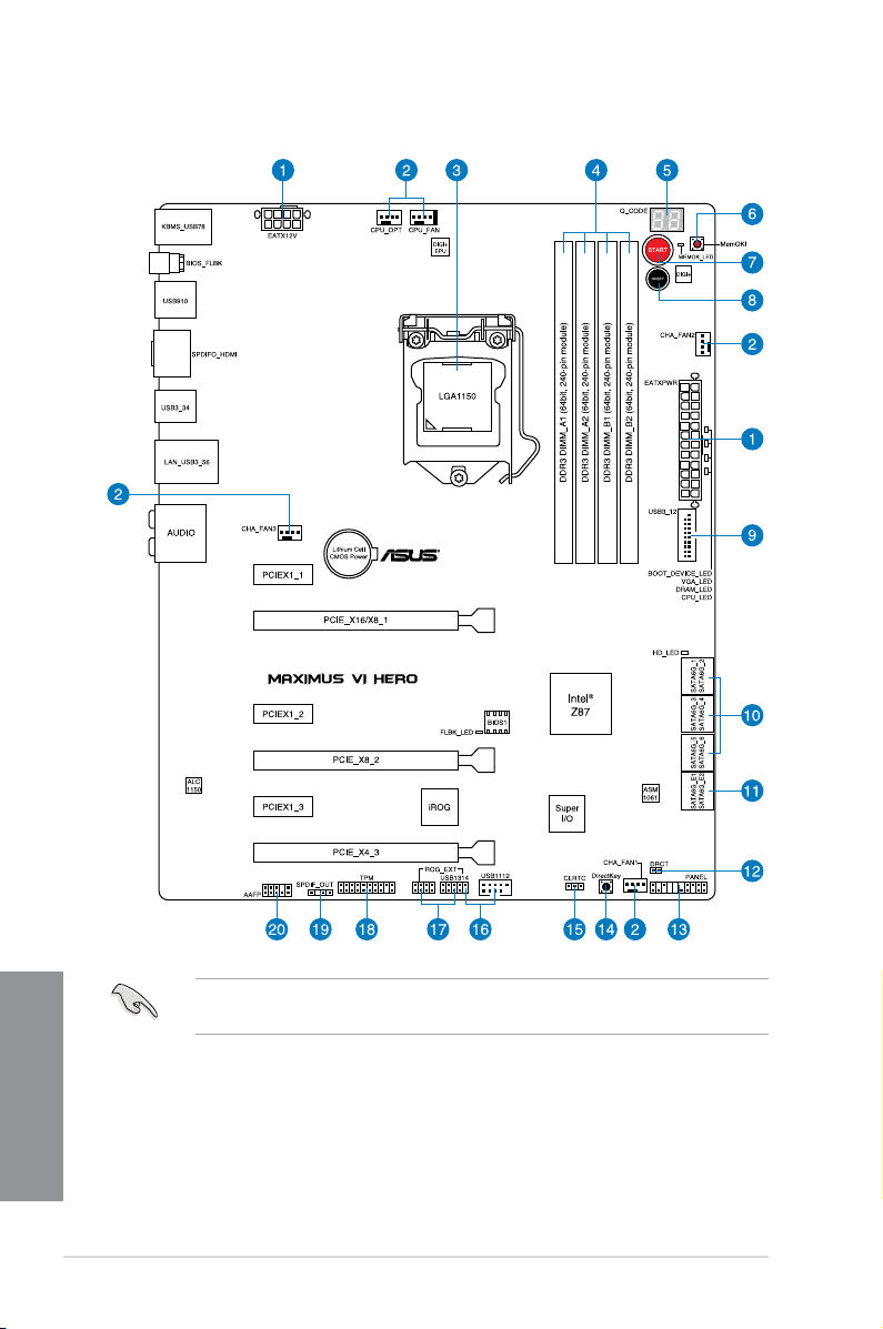
1.2.2 Motherboard layout
Chapter 1
1-6
Refer to 1.2.9 Internal connectors and 2.3.1 Rear I/O connection for more information
about rear panel connectors and internal connectors.
Chapter 1: Product introduction
Page 21

Layout contents
Connectors/Jumpers/Buttons and switches/Slots Page
1. ATX power connectors (24-pin EATXPWR; 8-pin EATX12V) 1-43
2. CPU, chassis, and optional fan connectors (4-pin CPU_FAN; 4-pin
CPU_OPT; 4-pin CHA_FAN1-3)
3. LGA1150 CPU Socket 1-8
4. DDR3 DIMM slots 1-9
5. Q_Code LEDs 1-31
6. MemOK! button 1-26
7. START (Power-on) button 1-25
8. RESET button 1-25
9. USB 3.0 connectors (20-1 pin USB3_12) 1-39
10. Intel® Z87 Serial ATA 6 Gb/s connectors (7-pin SATA6G_1-6 [red]) 1-38
11. ASMedia® Serial ATA 6 Gb/s connectors (7-pin SATA6G_E12/E34 [red]) 1-39
12. DirectKey connector (2-pin DRCT)DirectKey connector (2-pin DRCT) 1-45
13. System panel connector (20-8 pin PANEL) 1-44
14. DirectKey button 1-27
15. Clear RTC RAM (3-pin CLRTC) 1-28
16. USB 2.0 connectors (10-1 pin USB1112; USB1314) 1-41
17. ROG Extension connector (18-1 pin ROG_EXT) 1-46
18. TPM connector (20-1 pin TPM) 1-46
19. Digital audio connector (4-1 pin SPDIF_OUT) 1-40
20. Front panel audio connector (10-1 pin AAFP) 1-40
1-42
ASUS MAXIMUS VI HERO
Chapter 1
1-7
Page 22
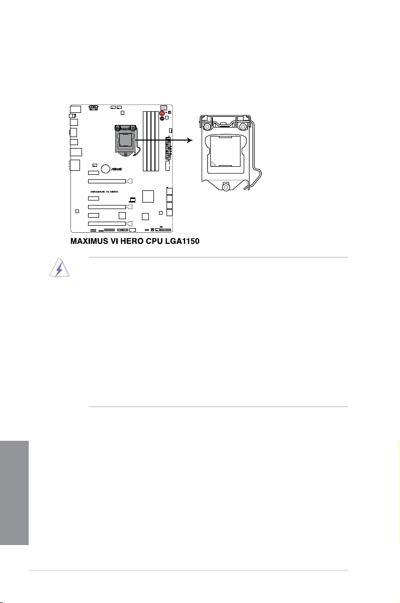
1.2.3 Central Processing Unit (CPU)
The motherboard comes with a surface mount LGA1150 socket designed for the 4th
Generation Intel® Core™ i7 / Intel® Core™ i5 / Intel® Core™ i3, Pentium®, and Celeron®
processors.
• Ensure that all power cables are unplugged before installing the CPU.Ensure that all power cables are unplugged before installing the CPU.
• Ensure that you install the correct CPU designed for LGA1150 only. DO NOT install a
CPU designed for LGA1155 and LGA1156 sockets on the LGA1150 socket.
• Upon purchase of the motherboard, ensure that the PnP cap is on the socket andUpon purchase of the motherboard, ensure that the PnP cap is on the socket and
the socket contacts are not bent. Contact your retailer immediately if the PnP cap
is missing, or if you see any damage to the PnP cap/socket contacts/motherboard
components. ASUS will shoulder the cost of repair only if the damage is shipment/
transit-related.
• Keep the cap after installing the motherboard. ASUS will process Return MerchandiseKeep the cap after installing the motherboard. ASUS will process Return Merchandise
Authorization (RMA) requests only if the motherboard comes with the cap on the
LGA1150 socket.
• The product warranty does not cover damage to the socket contacts resulting fromThe product warranty does not cover damage to the socket contacts resulting from
incorrect CPU installation/removal, or misplacement/loss/incorrect removal of the PnP
cap.
Chapter 1
1-8
Chapter 1: Product introduction
Page 23
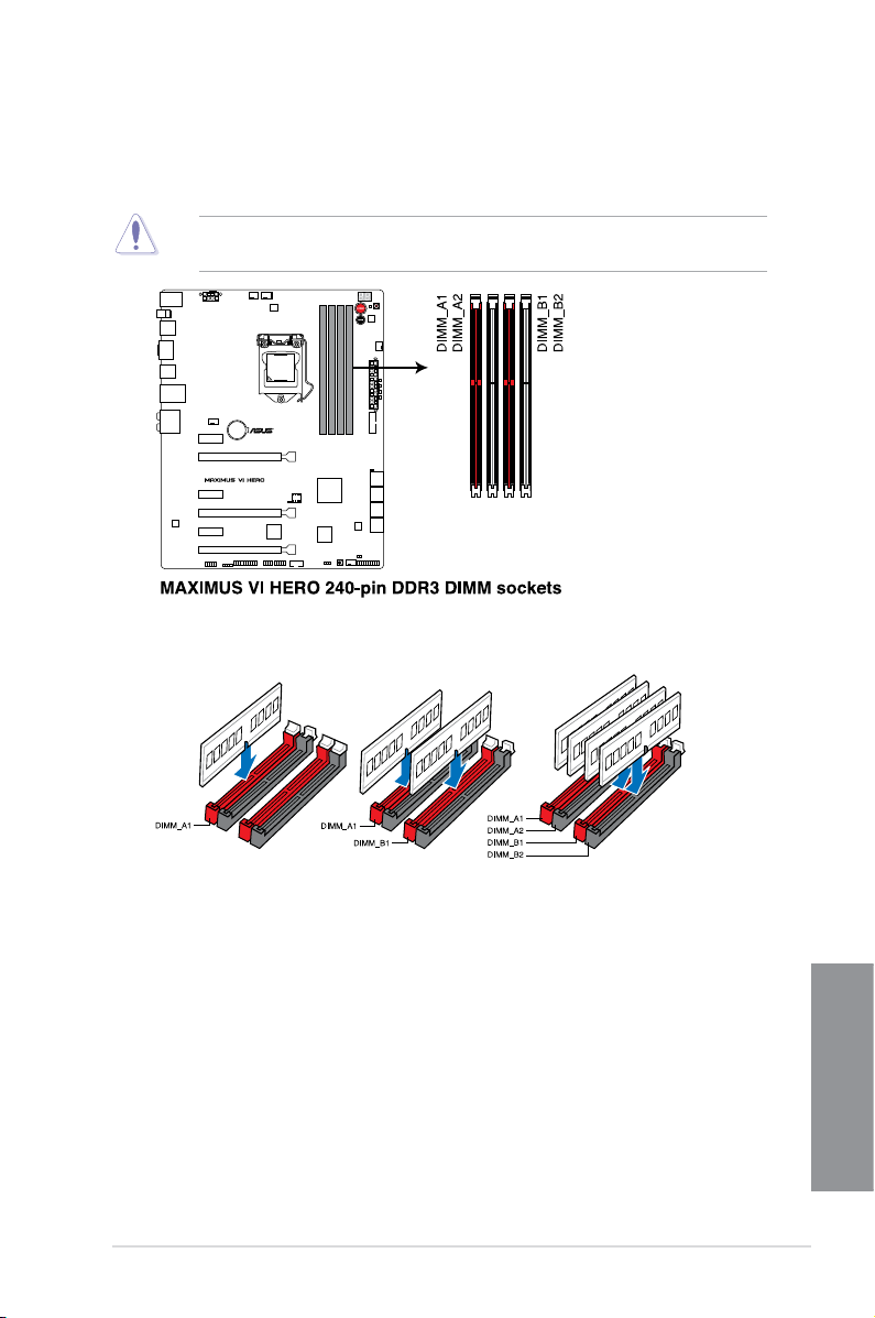
1.2.4 System memory
The motherboard comes with four Double Data Rate 3 (DDR3) Dual Inline Memory Modules
(DIMM) slots.
A DDR3 module is notched differently from a DDR or DDR2 module. DO NOT install a DDR
or DDR2 memory module to the DDR3 slot.
Recommended memory congurations
ASUS MAXIMUS VI HERO
Chapter 1
1-9
Page 24

Memory congurations
You may install 1GB, 2GB, 4GB and 8GB unbuffered and non-ECC DDR3 DIMMs into the
DIMM sockets.
• Memory module with memory frequency higher than 2133 MHz and its corresponding
timing or the loaded XMP prole is not the JEDEC memory standard. The stability and
compatibility of these memory modules depend on the CPU’s capabilities and other
installed devices.
• You may install varying memory sizes in Channel A and Channel B. The system mapsYou may install varying memory sizes in Channel A and Channel B. The system maps
the total size of the lower-sized channel for the dual-channel conguration. Any excess
memory from the higher-sized channel is then mapped for single-channel operation.
• According to Intel CPU spec, DIMM voltage below 1.65V is recommended to protectAccording to Intel CPU spec, DIMM voltage below 1.65V is recommended to protect
the CPU.
• Always install DIMMs with the same CAS latency. For optimal compatibility, weAlways install DIMMs with the same CAS latency. For optimal compatibility, we
recommend that you install memory modules of the same version or date code (D/C)
from the same vendor. Check with the retailer to get the correct memory modules.
• Due to the memory address limitation on 32-bit Windows OS, when you install 4GBDue to the memory address limitation on 32-bit Windows OS, when you install 4GB
or more memory on the motherboard, the actual usable memory for the OS can be
about 3GB or less. For effective use of memory, we recommend that you do any of the
following:
a) Use a maximum of 3GB system memory if you are using a 32-bit Windows OS.Use a maximum of 3GB system memory if you are using a 32-bit Windows OS.
b) Install a 64-bit Windows OS when you want to install 4GB or more on theInstall a 64-bit Windows OS when you want to install 4GB or more on thenstall a 64-bit Windows OS when you want to install 4GB or more on the
motherboard.
c) For more details, refer to the Microsoft® support site at http://support.microsoft.
com/kb/929605/en-us.
• This motherboard does not support DIMMs made up of 512Mb (64MB) chips or less
(Memory chip capacity counts in Megabit, 8 Megabit/Mb = 1 Megabyte/MB).
Chapter 1
1-10
• The default memory operation frequency is dependent on its Serial Presence DetectThe default memory operation frequency is dependent on its Serial Presence Detect
(SPD), which is the standard way of accessing information from a memory module.
Under the default state, some memory modules for overclocking may operate at a
lower frequency than the vendor-marked value. To operate at the vendor-marked or at
a higher frequency, refer to section 3.4 Extreme Tweaker menu for manual memory
frequency adjustment.
• For system stability, use a more efcient memory cooling system to support a fullFor system stability, use a more efcient memory cooling system to support a full
memory load (4 DIMMs) or overclocking condition.
Chapter 1: Product introduction
Page 25
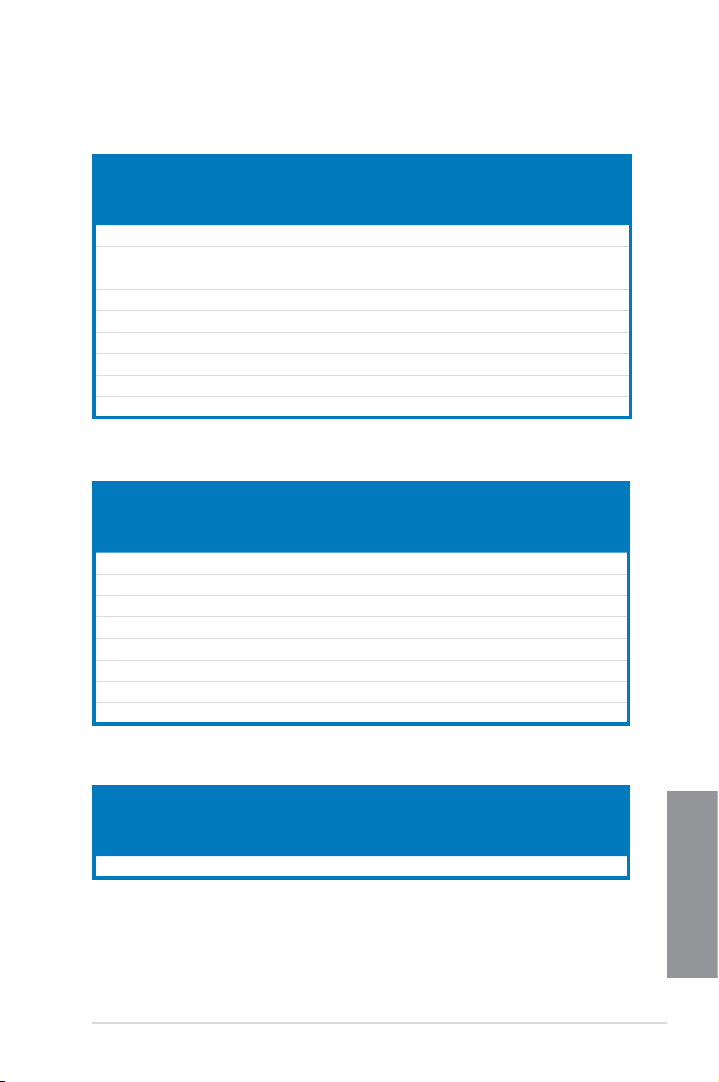
MAXIMUS VI HERO Motherboard Qualied Vendors Lists (QVL)
DDR3 2800 MHz capability
Vendors Part No. Size SS/DSChip
AVEXIR AVD3U28001204G-4CI 16GB ( 4x 4GB ) DS - - 12-14-14-35 1.65V • •
CORSAIR CMD16GX3M4A2800C11 16GB ( 4x 4GB ) DS - - 11-14-14-35 1.65V • •
CORSAIR CMD16GX3M4A2800C12 16GB ( 4x 4GB ) DS - - 12-14-14-36 1.65V • •
G.SKILL F3-2800C11D-8GTXD 8GB ( 2x 4GB ) DS - - 11-13-13-35 1.65V • •
G.SKILL F3-2800C11Q-16GTXD 16GB ( 4x 4GB ) DS - - 11-13-13-35 1.65V • •
G.SKILL F3-2800C11D-8GTXDG 8GB ( 2x 4GB ) DS - - 11-14-14-35 1.65V • •
G.SKILL F3-2800C11Q-16GTXDG 16GB ( 4x 4GB ) DS - - 11-13-13-35 1.65V • •
G.SKILL F3-2800C12Q-32GTXG 32GB (4 x 8GB ) DS - - 12-13-13-35 1.65V • •
G.SKILL F3-2800C10D-8GBTXD 8GB ( 2x 4GB ) DS - - 10-13-13-35 1.65V • •
Brand
Chip
Timing Voltage DIMM
NO.
socket
support
(Optional)
2 4
DDR3 2666 MHz capability
Vendors Part No. Size SS/DSChip
Apacer 78.BAGFF.AFC0C(XMP) 8GB ( 2x 4GB ) DS - - 12-13-13-35 - • •
Apacer 78.BAGFR.AFD0C(XMP) 8GB ( 2x 4GB ) DS - - 12-13-13-35 - • •
Apacer 78.CAGFF.AFD0C(XMP) 16GB ( 2x 8GB ) DS - - 12-13-13-35 - • •
G.SKILL F3-2666C11Q-32GTXD(XMP) 32GB ( 4x 8GB ) DS - - - 1.65 • •
G.SKILL F3-2666CL10Q-16GBZHD(XMP) 16GB ( 4x 4GB ) DS - - 10-12-12-31 1.65 •
GEIL GOC332GB2666C11QC(XMP) 32GB ( 4x 8GB ) DS - - 11-13-13-32 1.65 • •
Team TXD34G2666HC11CBK(XMP) 8GB ( 2x 4GB ) SS - - 11-13-13-35 1.65 • •
Team TXD38G2666HC11CBK(XMP) 16GB ( 2x 8GB ) DS - - 11-13-13-35 1.65 •
Brand
Chip
Timing Voltage DIMM
NO.
socket
support
(Optional)
2 4
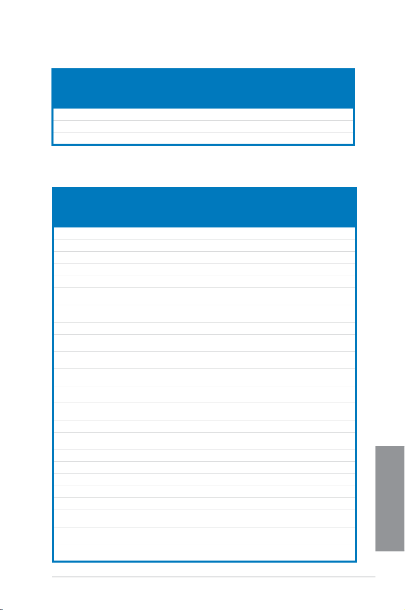
DDR3 2600 MHz capability
Vendors Part No. Size SS/DSChip
A-DATA AX3U2600GW8G11(XMP) 16GB ( 2x 8GB ) DS - - 11-13-13-35 1.65 • •
ASUS MAXIMUS VI HERO
Brand
Chip
Timing Voltage DIMM
NO.
socket
support
(Optional)
2 4
Chapter 1
1-11
Page 26

DDR3 2500 MHz capability
Vendors Part No. Size SS/DSChip
G.SKILL F3-20000CL10Q-16GBZHD(XMP) 16GB ( 4x 4GB ) DS - - 10-11-11-31 1.65 • •
DDR3 2400 MHz capability
Vendors Part No. Size SS/DS Chip
A-DATA AX3U2400GC4G10(XMP) 4GB DS - - 10-12-12-31 1.65 • •
A-DATA AX3U2400GW8G11(XMP) 16GB ( 2x 8GB ) DS - - 11-13-13-35 1.65 • •
Apacer 78.BAGFL.AFD0C(XMP) 8GB ( 2x 4GB ) DS - - 11-12-12-30 - • •
Apacer 783BAGF3.AFD0C(XMP) 8GB ( 2x 4GB ) DS - - 11-11-11-30 - • •
CORSAIR CMGTX8(XMP) 8GB ( 4x 2GB ) SS - - 10-12-10-30 1.65 • •
CORSAIR CMZ16GX3M2A2400C10
CORSAIR CMZ16GX3M4A2400C9R
G.SKILL F3-19200CL10Q-
G.SKILL F3-19200CL11Q-
G.SKILL F3-19200CL11Q-
G.SKILL F3-19200CL9D-
G.SKILL F3-19200CL9Q-
GEIL GET34GB2400C9DC
GEIL GOC316GB2400C10QC
GEIL GOC316GB2400C11QC
Kingston KHX2400C11D3K4/
KINGSTON KHX24C11K4/16X(XMP) 16GB ( 4x 4GB ) DS - - 11-13-13-30 1.65 • •
Chapter 1
KINGSTON KHX24C11T2K2/8X(XMP) 8GB ( 2x 4GB ) DS - - - 1.65 • •
KINGSTON KHX24C11T3K4/32X(XMP) 32GB ( 4x 8GB ) DS - - 9-9-9-24 1.65 • •
Patriot PVV34G2400C9K(XMP) 4GB ( 2x 2GB ) DS - - 9-11-9-27 1.66 •
Patriot PXD38G2400C11K(XMP) 8GB ( 2x 4GB ) DS - - 11-11-11-30 1.65 • •
Patriot PXD38G2400C11K(XMP) 8GB ( 2x 4GB ) DS - - 2400 11-11-11-30 1.65 • •
Team TXD38G2400HC10QBK
(Ver4.21)
(Ver4.13)(XMP)
32GBZHD(XMP)
16GBZHD(XMP)
16GBZHD(XMP)
4GBPIS(XMP)
16GBZMD(XMP)
(XMP)
(XMP)
(XMP)
8GX(XMP)
(XMP)
Chip
Brand
Brand
16GB ( 2x 8GB ) DS - - 10-12-12-31 1.65 • •
16GB ( 4x 4GB ) DS - - 2400 9-11-11-31 1.65 • •
32GB ( 4x 8GB ) DS - - 10-12-12-31 1.65 • •
16GB ( 4x 4GB ) DS - - 11-11-11-31 1.65 • •
16GB ( 4x 4GB ) DS - - 11-11-11-31 1.65 • •
4G ( 2x 2G ) DS - - 9-11-9-28 1.65 •
16GB ( 4x 4GB ) DS - - 9-11-11-31 1.65 • •
4GB ( 2x 2GB ) DS - - 9-11-9-27 1.65 •
16GB ( 4x 4GB ) DS - - 10-11-11-30 1.65 • •
16GB ( 4x 4GB ) DS - - 11-11-11-30 1.65 • •
8GB ( 4x 2GB ) SS - - 11-13-11-30 1.65 • •
8GB DS - - 10-12-12-31 1.65 • •
Timing Voltage DIMM
NO.
Chip
Timing Voltage DIMM
NO.
socket
support
(Optional)
2 4
socket
support
(Optional)
2 4
1-12
Chapter 1: Product introduction
Page 27
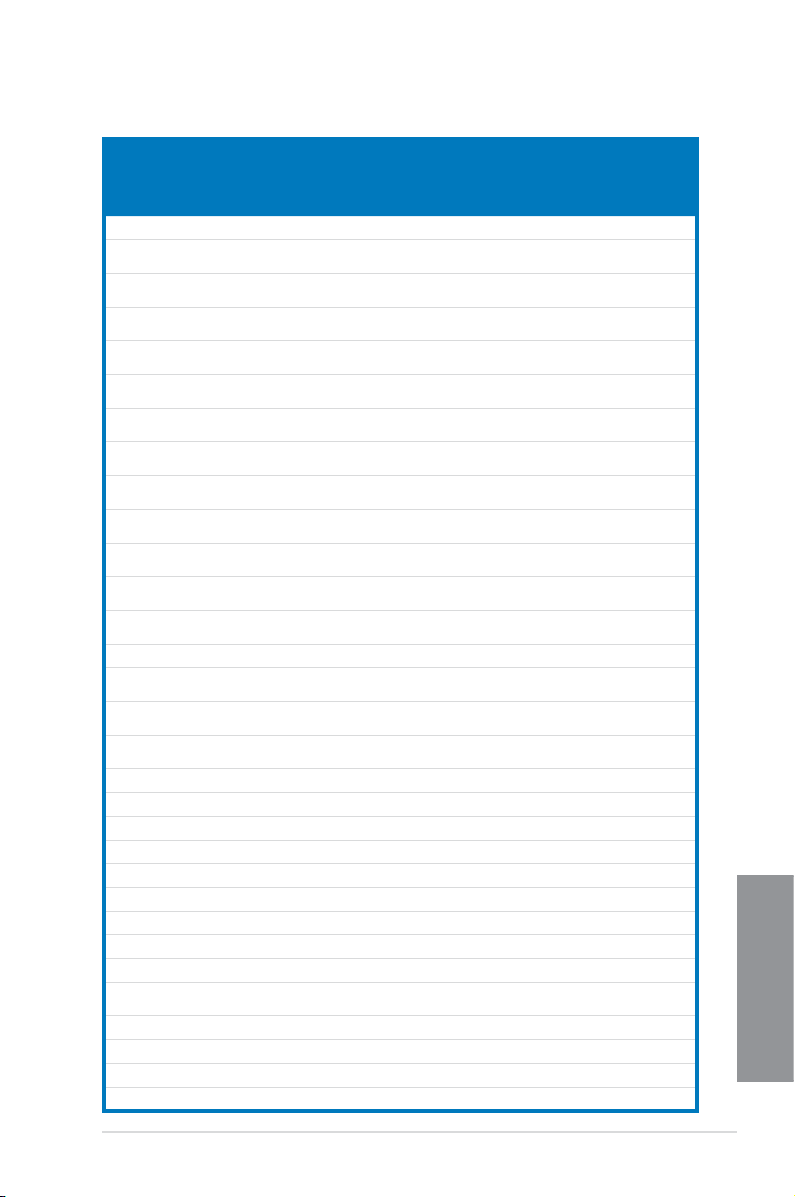
DDR3 2200 MHz capability
Vendors Part No. Size SS/DSChip
G.SKILL F3-17600CL7D-4GBFLS(XMP) 4G ( 2x 2G ) DS - - 7-10-10-28 1.65 •
GEIL GET34GB2200C9DC(XMP) 4GB ( 2x 2GB ) DS - - 9-10-9-28 1.65 • •
GEIL GET38GB2200C9ADC(XMP) 8GB ( 2x 4GB ) DS - - 9-11-9-28 1.65 • •
Brand
Chip
Timing Voltage DIMM
NO.
socket
support
(Optional)
2 4
DDR3 2133 MHz capability
Vendors Part No. Size SS/DSChip
A-DATA AX3U2133XC4G10(XMP) 4GB DS - - 10-11-11-30 1.65 • •
A-DATA AX3U2133XW8G10(XMP) 16GB ( 2x 8GB ) DS - - 10-11-11-30 1.65 • •
A-DATA AX3U2133XW8G10(XMP) 8GB DS - - 10-11-11-30 1.65 • •
Apacer 78.BAGE4.AFD0C(XMP) 8GB ( 2x 4GB ) DS - - 9-9-9-24 - • •
Apacer AHU04GFB33CAQ3R(XMP) 4GB DS - - 11-13-13-31 - • •
CORSAIR CMD8GX3M2A2133C9
CORSAIR CMT4GX3M2B2133C9(Ver
CORSAIR CMT4GX3M2B2133C9(XMP) 4GB ( 2x 2GB ) DS - - 9-10-9-27 1.5 • •
G.SKILL F3-17000CL11Q2-
G.SKILL F3-17000CL9Q-
G.SKILL F3-17000CL9Q-
G.SKILL F3-17066CL9D-
G.SKILL F3-17066CL9Q-
G.SKILL F3-2133C11Q-32GZL(XMP) 32GB ( 4x 8GB ) DS - - 11-11-11-31 1.5 • •
KINGSTON KHX2133C11D3K4/
KINGSTON KHX21C11T3FK8/64X(XMP) 64GB ( 8x 8GB ) DS - - 9-9-9-24 1.5 • •
OCZ OCZ3XTEP2133C9LV4GK 2GB DS - - 7-7-7-20 1.65 •
Patriot PV316G213C1K(XMP) 16GB ( 2x 8GB ) DS - - 11-11-11-30 1.5 • •
Patriot PVV34G2133C9K(XMP) 4GB ( 2x 2GB ) DS - - 9-11-9-27 1.66 • •
Patriot PXD38G2133C11K(XMP) 8GB ( 2x 4GB ) DS - - 9-9-9-24 1.65 •
Patriot PXD38G2133C11K(XMP) 8GB ( 2x 4GB ) DS - - 2133 11-11-
Team TLD38G2133HC11ABK
Team TXD34096M2133HC11A-
(Ver1.5)(XMP)
7.1)(XMP)
64GBZLD(XMP)
16GBXLD(XMP)
16GBZH(XMP)
8GBPID(XMP)
16GBTDD(XMP)
16GX(XMP)
(XMP)
V(XMP)
8GB ( 2x 4GB ) DS - - 9-11-10-27 1.5 •
4GB ( 2x 2GB ) DS - - 9-10-9-27 1.5 • •
64GB ( 8x 8GB ) DS - - 11-11-11-30 1.5 • •
16GB ( 4x 4GB ) DS - - 9-11-9-28 1.65 • •
16GB ( 4x 4GB ) DS - - 9-11-10-28 1.65 • •
8GB ( 2x 4GB ) DS - - 9-9-9-24 1.65 • •
16GB ( 4x 4GB ) DS - - 9-9-9-24 1.65 •
16GB ( 4x 4GB ) DS - - 11-12-11-30 1.65 • •
8GB DS - - 11-11-11-31 1.65 • •
4GB DS - - 11-11-11-31 1.65 • •
Brand
Chip
Timing Voltage DIMM
NO.
11-27
socket
support
(Optional)
2 4
1.5 • •
Chapter 1
ASUS MAXIMUS VI HERO
1-13
Page 28

DDR3 2000 MHz capability
Vendors Part No. Size SS/DSChip
AEXEA AXA3ES2G2000LG28V
(XMP)
AEXEA AXA3ES4GK2000LG28V
(XMP)
Apacer 78.AAGD5.9KD (XMP) 6GB ( 3x 2GB ) DS - - 9-9-9-27 - • •
Asint SLA302G08-ML2HB
(XMP)
G.SKILL F3-16000CL9D-4GBRH
(XMP)
G.SKILL F3-16000CL9D-4GBTD
(XMP)
GEIL GUP34GB2000C9DC
(XMP)
Patriot PV736G2000ELK (XMP) 6GB ( 3x 2GB ) DS - - 7-7-7-20 1.65 • •
Patriot PVT36G2000LLK (XMP) 6GB ( 3x 2GB ) DS - - 8-8-8-24 1.65 • •
Patriot PX7312G2000ELK
(XMP)
Silicon
SP002GBLYU200S02
Power
(XMP)
Team TXD32048M2000C9
(XMP)
Team TXD32048M2000C9-L
(XMP)
Team TXD32048M2000C9-L
(XMP)
2GB DS - - - 1.65 • •
4GB ( 2x 2GB ) DS - - - 1.65 • •
4GB DS Hynix H5TQ2G83BFRH9C 9-9-9-27 - • •
4GB ( 2x 2GB ) DS - - 9-9-9-24 1.65 •
4GB ( 2x 2GB ) DS - - 9-9-9-24 1.65 •
4GB ( 2x 2GB ) DS - - 9-9-9-28 1.65 • •
12GB ( 3x 4GB ) DS - - 9-11-
2GB DS - - - - • •
2GB DS Team T3D1288RT-20 9-9-9-24 1.5 • •
2GB DS Team T3D1288LT-20 9-9-9-24 1.5 • •
2GB DS Team T3D1288RT-20 9-9-9-24 1.6 • •
Chip NO. Timing Voltage DIMM
Brand
9-27
socket
support
(Optional)
2 4
1.65 • •
Chapter 1
1-14
Chapter 1: Product introduction
Page 29
DDR3 1866 MHz capability
Vendors Part No. Size SS/DSChip
A-DATA AX3U1866XW8G10(XMP) 16GB ( 2x 8GB ) DS - - 10-11-10-30 1.5 • •
CORSAIR CMD16GX3M2A1866C9
CORSAIR CMD16GX3M4A1866C9
CORSAIR CMD16GX3M4A1866C9
CORSAIR CMD8GX3M2A1866C9
CORSAIR CMD8GX3M2A1866C9
CORSAIR CMD8GX3M2A1866C9
CORSAIR CMT32GX3M4X1866C9(Ver3
CORSAIR CMZ16GX3M4X1866C9R
CORSAIR CMZ16GX3M4X1866C9R(Ver
CORSAIR CMZ32GX3M4X1866C10
CORSAIR CMZ32GX3M4X1866C10(Ver
CORSAIR CMZ8GX3M2A1866C9
CORSAIR CMZ8GX3M2A1866C9(XMP) 8GB ( 2x 4GB ) DS - - 9-10-9-27 1.5 •
CORSAIR CMZ8GX3M2A1866C9G
Crucial BLE4G3D1869DE1XT0.16F
G.SKILL F3-14900CL10Q2-
G.SKILL F3-14900CL9D-8GBSR(XMP) 8GB ( 2x 4GB ) DS - - 9-10-9-28 1.5 • •
G.SKILL F3-14900CL9Q-16GBXL(XMP) 16GB ( 4x 4GB ) DS - - 9-10-9-28 1.5 • •
G.SKILL F3-14900CL9Q-16GBZL(XMP) 16GB ( 4x 4GB ) DS - - 9-10-9-28 1.5 • •
G.SKILL F3-14900CL9Q-8GBFLD(XMP) 8GB ( 2x 4GB ) DS - - 9-9-9-24 1.6 • •
G.SKILL F3-1866C9Q-32GXM(XMP) 32GB ( 4x 8GB ) DS - - 9-10-9-28 1.5 • •
KINGSTON KHX1866C9D3K2/8GX(XMP) 8GB ( 2x 4GB ) DS - - - 1.65 • •
Patriot PXD34G1866ELK(XMP) 4GB ( 2x 2GB ) SS - - 9-9-9-24 1.65 • •
Patriot PXD38G1866ELK(XMP) 8GB ( 2x 4GB ) DS - - 9-11-9-27 1.65 • •
Patriot PXD38G1866ELK(XMP) 8GB ( 2x 4GB ) DS - - 9-11-9-27 1.65 • •
Patriot PXD38G1866ELK(XMP) 8GB ( 2x 4GB ) DS - - 1866 9-10-
Team TED34G1866HC13BK 4GB SS - - - - • •
Team TED38G1866HC-13BK 8GB DS - - - - • •
Team TLD34G1866HC9KBK(XMP) 4GB DS - - 9-11-9-27 1.5 • •
Team TLD38G1866HC10SBK(XMP) 8GB DS - - 10-11-10-30 1.5 • •
(Ver5.29)(XMP)
(Ver4.13)(XMP)
(Ver8.16)(XMP)
(Ver4.13)(XMP)
(Ver5.12)(XMP)
(Ver8.16)(XMP)
.23)(XMP)
(Ver8.16)(XMP)
8.16)(XMP)
(Ver3.23)(XMP)
3.23)(XMP)
(Ver8.16)(XMP)
(Ver5.12)(XMP)
MD(XMP)
64GBZLD(XMP)
16GB ( 2x 8GB ) DS - - 1866 9-9-9-27 1.5 •
16GB ( 4x 4GB ) DS - - 9-10-9-27 1.5 • •
16GB ( 4x 4GB ) DS - - 9-10-9-27 1.5 • •
8GB ( 2x 4GB ) DS - - - 1.5 • •
8GB ( 2x 4GB ) DS - - 9-10-9-27 1.5 •
8GB ( 2x 4GB ) DS - - 9-10-9-27 1.5 •
32GB ( 4x 8GB ) DS - - 9-10-9-27 1.5 • •
16GB ( 4x 4GB ) DS - - 9-10-9-27 1.5 • •
16GB ( 4x 4GB ) DS - - 9-10-9-27 1.5 • •
32GB ( 4x 8GB ) DS - - 10-11-10-27 1.5 • •
32GB ( 4x 8GB ) DS - - 10-11-10-27 1.5 • •
8GB ( 2x 4GB ) DS - - 9-10-9-27 1.5 • •
8GB ( 2x 4GB ) DS - - 1866 9-10-
4GB DS - - 9-9-9-27 1.5 • •
64GB ( 8x 8GB ) DS - - 10-11-10-30 1.5 • •
Brand
Chip
Timing Voltage DIMM
NO.
9-27
9-27
socket
support
(Optional)
2 4
1.5 • •
1.5 • •
Chapter 1
ASUS MAXIMUS VI HERO
1-15
Page 30
DDR3 1800 MHz capability
Vendors Part No. Size SS/DSChip
G.SKILL F3-14400CL9D-4GBRL(XMP) 4GB ( 2x 2GB ) DS - - 9-9-9-24 1.65 • •
Brand
Chip
Timing Voltage DIMM
NO.
DDR3 1600 MHz capability
socket
support
(Optional)
2 4
Vendors Part No. Size SS/DSChip
A-DATA AD3U1600C2G11 2GB SS MICRON D9PFJ 11-11-11-28 - • •
A-DATA AD3U1600C4G11 4GB DS MICRON D9PFJ 11-11-11-28 - • •
A-DATA AD3U1600W4G11 4GB SS A-DATA 3WCD-1211A 11-11-11-28 - • •
A-DATA AD3U1600W8G11 8GB DS A-DATA 3WCD-1211A 11-11-11-28 - • •
A-DATA AX3U1600GW8G9
A-DATA AX3U1600W8G11 16GB
A-DATA AXDU1600GW8G9B
AMD AE32G1609U1-U 2GB SS AMD 23EY4587MB6H - 1.5 • •
AMD AE34G1609U2-U 4GB DS AMD 23EY4587MB6H - 1.5 • •
AMD AP38G1608U2K
Apacer 78.B1GE3.9L10C 4GB DS Apacer AM5D5908DEQSCK - 1.65 • •
Apacer 78.B1GET.9K00C 4GB SS Apacer AM5D6008BQQSCK 11-11-11-28 - • •
Apacer 78.C1GET.9K10C 8GB DS Apacer AM5D6008BQQSCK 11-11-11-31 - • •
Apacer AHU04GFA60C9Q3R
Apacer AHU08GFA60CBT3R
Asint SLA302G08-EGG1C
Asint SLA302G08-EGJ1C
Asint SLA302G08-EGN1C 4GB DS ASint 302G08-GN1C - - • •
Chapter 1
Asint SLA304G08-ENG1B 4GB SS Asint 304G08-GN1B 9-11-11-28 - • •
Asint SLB304G08-EGJ1B
Asint SLB304G08-EGN1B 8GB DS ASint 304G08-GN1B - - • •
Asint SLZ302G08-EGN1C 2GB SS ASint 302G08-GN1C - - • •
Asint SLZ3128M8-
ATP AQ12M64B8BKK0S 4GB DS SAMSUNG K4B2G08460 - NO • •
(XMP)
(XMP)
(XMP)
(XMP)
(XMP)
(XMP)
(XMP)
(XMP)
EGJ1D(XMP)
Brand
16GB
DS - - 9-9-9-24 1.5 • •
(2x8GB )
DS - - 9-11-9-27 1.5 • •
(2x8GB )
16GB
DS - - 9-11-9-27 1.65 • •
(2x8GB )
8GB
DS - - 9-9-9-28 1.65 • •
(2x4GB )
4GB DS - - 11-11-11-28 - • •
8GB DS - - 9-9-9-24 - • •
4GB DS Asint 302G08-GG1C 9-9-9-27 - • •
4GB DS Asint 302G08-GJ1C 9-9-9-27 - • •
8GB DS - - 9-9-9-27 - • •
2GB DS Asint 3128M8-GJ1D - - • •
Chip NO. Timing Voltage DIMM
socket
support
(Optional)
2 4
(continued on the next page)
1-16
Chapter 1: Product introduction
Page 31

DDR3 1600 MHz capability
Vendors Part No. Size SS/DSChip
CORSAIR CMD16GX3M2A1600C9
(Ver8.21)(XMP)
CORSAIR CMD8GX3M2A1600C8
(Ver5.12)(XMP)
CORSAIR CMD8GX3M2A1600C9
(Ver2.12)(XMP)
CORSAIR CMG4GX3M2A1600C6 4GB
CORSAIR CML16GX3M4X1600C8
(Ver 2.12)(XMP)
CORSAIR CMP6GX3M3A1600C8
(XMP)
CORSAIR CMP6GX3M3A1600C8
(XMP)
CORSAIR CMX6GX3M3C1600C7
(XMP)
CORSAIR CMX8GX3M2A1600C9
(Ver3.19)(XMP)
CORSAIR CMZ16GX3M2A1600C10
(Ver.3.24)(XMP)
CORSAIR CMZ16GX3M4A1600C9
(XMP)
CORSAIR CMZ32GX3M4X1600C10
(Ver2.2)(XMP)
CORSAIR CMZ8GX3M2A1600C8
(XMP)
CORSAIR CMZ8GX3M4X1600C9
(Ver 2.12)(XMP)
CORSAIR HX3X12G1600C9 (XMP) 12GB
Crucial BL12864BN1608.8FF
(XMP)
Crucial BLT4G3D1608DT1TX
0.16FM (XMP)
EK
EKM324L28BP8-I16
Memory
(XMP)
EK
EKM324L28BP8-I16
Memory
(XMP)
Elixir M2X2G64CB88G7N-DG
(XMP)
Elixir M2X4G64CB8HG5N-DG
(XMP)
Elixir M2X8G64CB8HB5N-DG
(XMP)
G.SKILL F3-12800CL7D-8GBRH
(XMP)
G.SKILL F3-12800CL7Q-16GBXH
(XMP)
G.SKILL F3-12800CL8D-
8GBECO (XMP)
16GB
(2x8GB )
8GB
(2x4GB )
8GB
(2x4GB )
(2x2GB )
16GB
(4x4GB )
6GB
(3x2GB )
6GB
(3x2GB )
6GB
(3x2GB )
8GB
(2x4GB )
16GB
(2x8GB )
16GB
(4x4GB )
32GB
(4x8GB )
8GB
(2x4GB )
8GB
(4x2GB )
(6x2GB )
2GB
(2x1GB )
4GB DS - - 8-8-8-24 1.5 • •
4GB
(2x2GB )
4GB
(2x2GB )
2GB SS Elixir N2CB2G80GN-DG 9-9-9-28 - • •
4GB DS Elixir N2CB2G80GN-DG 9-9-9-28 - • •
8GB DS Elixir N2CB4G80BN-DG 9-9-9-28 1.5 • •
8GB
(2x4GB )
16GB
(4x4GB )
8GB
(2x4GB )
Brand
DS - - 9-9-9-24 1.5 •
DS - - 1600 8-8-
DS - - 9-9-9-24 1.5 • •
DS - - 6-6-6-18 1.65 • •
DS - - Heat-Sink
DS - - 8-8-8-24 1.65 • •
DS - - 8-8-8-24 1.65 • •
DS - - 7-8-7-20 1.65 • •
SS - - 9-9-9-24 1.65 • •
DS - - 10-10-10-27 1.5 • •
DS - - 9-9-9-24 1.5 • •
DS - - 10-10-10-27 1.5 • •
DS - - 8-8-8-24 1.5 • •
SS - - 9-9-9-24 1.5 • •
DS - - 9-9-9-24 1.6 • •
SS - - 8-8-8-24 1.65 • •
DS - - 9 - • •
DS - - 9 - • •
DS - - 7-8-7-24 1.6 • •
DS - - 7-8-7-24 1.6 • •
DS - - 8-8-8-24 1.35 •
(continued on the next page)
Chip NO. Timing Voltage DIMM
8-24
Package
socket
support
(Optional)
2 4
1.5 • •
1.5 • •
Chapter 1
ASUS MAXIMUS VI HERO
1-17
Page 32

DDR3 1600 MHz capability
Vendors Part No. Size SS/DSChip
G.SKILL F3-12800CL9D-
G.SKILL F3-12800CL9D-
G.SKILL F3-12800CL9Q-
G.Skill F3-12800CL9Q-
G.SKILL F3-1600C9Q-32GXM
GEIL GET316GB1600C9QC
GEIL GUP34GB1600C7DC
GoodRam GR1600D364L9/2G 2GB DS GoodRam GF1008KC-JN - - • •
KINGMAX FLGE85F-C8KL9A
KINGMAX FLGF65F-C8KL9A
KINGSTON KHX16009CD3K2/
KINGSTON KHX1600C9D3B1/4G
KINGSTON KHX1600C9D3K3/
KINGSTON KHX1600C9D3K3/
KINGSTON KHX1600C9D3K3/
KINGSTON KHX1600C9D3K4/
KINGSTON KHX1600C9D3K6/
KINGSTON KHX1600C9D3K8/
KINGSTON KHX1600C9D3LK2/
KINGSTON KHX1600C9D3P1K2/8G8GB
KINGSTON KHX16C10B1K2/
Chapter 1
KINGSTON KHX16C9K2/16 16GB
KINGSTON KHX16C9P1K2/16 16GB
KINGSTON KVR16N11/4 4G DS Hynix H5TQ2G83CFRPBC - 1.5 • •
KINGTIGER KTG2G1600PG3
MICRON MT16JTF1G64AZ-
8GBRL (XMP)
8GBSR2 (XMP)
16GBXL (XMP)
16GBZL (XMP)
(XMP)
(XMP)
(XMP)
(XMP)
(XMP)
8GX(XMP)
(XMP)
12GX (XMP)
6GX(XMP)
6GX(XMP)
16GX(XMP)
24GX(XMP)
32GX(XMP)
8GX(XMP)
16X(XMP)
(XMP)
1G6D1
Brand
8GB
DS - - 9-9-9-24 1.5 • •
(2x4GB )
8GB
DS - - 9-9-9-24 1.25 • •
(2x4GB )
16GB
DS - - 9-9-9-24 1.5 • •
(4x4GB )
16GB
DS - - 9-9-9-24 1.5 • •
(4x4GB )
32GB
DS - - - 1.5 • •
(4x8GB )
16GB
DS - - 9-9-9-28 1.6 • •
(4x4GB )
4GB
DS - - 7-7-7-24 1.6 • •
(2x2GB )
2GB SS KINGMAX N/A 9-9-9-28 - • •
4GB DS KINGMAX N/A 9-9-9-28 - • •
8GB
DS - - 9-9-9-27 1.65 • •
(2x4GB )
4GB SS - - 9-9-9-27 1.65 • •
12GB
DS - - 9 1.65 • •
(3x4GB )
6GB
DS - - 9 1.65 • •
(3x2GB )
6GB
DS - - 9 1.65 • •
(3x2GB )
16GB
DS - - 9-9-9-24 1.65 • •
(4x4GB )
24GB
DS - - 9 1.65 • •
(6x4GB )
32GB
DS - - 9-9-9-27 1.65 • •
(8x4GB )
8GB
DS - - 9-9-9-24 1.35 • •
(2x4GB )
DS - - 9 1.5 • •
(2x4GB )
16GB
DS - - - 1.5 • •
(2x8GB )
DS - - 1333-9-9( 2x
8GB )
DS - - - 1.5 • •
(2x8GB )
2GB DS - - - - • •
8GB DS MICRON D9PBC - 1.5 • •
Chip NO. Timing Voltage DIMM
9-24
socket
support
(Optional)
2 4
1.5 • •
(continued on the next page)
1-18
Chapter 1: Product introduction
Page 33

DDR3 1600 MHz capability
Vendors Part No. Size SS/DSChip
Micron MT16JTF1G64AZ-
MICRON MT16KTF51264AZ-
Micron MT8JTF51264AZ-
MICRON MT8KTF25664AZ-
Mushkin 996805(XMP) 4GB
Mushkin 998805(XMP) 6GB
OCZ OCZ3BE1600C8LV4GK 4GB
Patriot PGD316G1600ELK
Patriot PGD316G1600ELK
Patriot PGD38G1600ELK
Patriot PGD38G1600ELK(XMP) 8GB
Patriot PGS34G1600LLKA 4GB
Patriot PGS34G1600LLKA2 4GB
Patriot PV38G160C9KRD
Patriot PVV38G1600LLK (XMP) 8GB
Patriot PX7312G1600LLK
Patriot PXD38G1600LLK (XMP) 8GB
PSC AL9F8L93B-GN2E 4GB SS PSC A3P4GF3BLF - - • •
PSC ALAF8L93B-GN2E 8GB DS PSC A3P4GF3BLF - - • •
SanMax SMD-4G68HP-16KZ 4GB DS Hynix H5TQ2G83BFRPBC - 1.5 • •
SanMax SMD-4G68NG-16KK 4GB DS ELPIDA J2108BDBG-GN-F - - • •
Silicon
Power
Silicon
Power
Team TXD34096M1600HC9-
Transcend JM1600KLH-8G
Transcend TS1GLK64V6H
Transcend TS1GLK64W6H 8GB DS SAMSUNG K4B4G0846B 11-11-11-
Transcend TS512MLK64W6H 4GB SS SAMSUNG K4B4G0846B 11-11-11-
1G6E1
1G6M1
1G6E1
1G6M1
(XMP)
(XMP)
(XMP)
(XMP)
(XMP)
SP002GBLTU160V02
(XMP)
SP004GBLTU160V02
(XMP)
D (XMP)
(626633)
(620945)
8GB DS Micron D9QBJ - - • •
4GB DS MICRON D9PFJ - - • •
4GB SS Micron D9QBJ - - • •
2GB SS MICRON D9PFJ - - • •
(2x2GB )
(3x2GB )
(2x2GB )
16GB
(2x8GB )
16GB
(2x8GB )
8GB
(2x4GB )
(2x4GB )
(2x2GB )
(2x2GB )
8GB
(2x4GB )
(2x4GB )
12GB
(3x4GB )
(2x4GB )
2GB SS S-POWER 20YT5NG 9-11-11-28 1.5 • •
4GB DS S-POWER 20YT5NG 9-9-9-24 1.5 • •
4GB DS Hynix H5TC2G83BFRH9A 9-9-9-24 1.5 • •
8GB DS Transcend TK963EBF3 - - • •
8GB DS SAMSUNG K4B4G0846B - - • •
Brand
DS - - 6-8-6-24 1.65 • •
DS - - 6-8-6-24 1.65 • •
DS - - 8-8-8 1.65 •
DS - - - 1.65 • •
DS - - 9-9-9-24 1.5 •
DS - - 9-9-9-24 1.65 • •
DS - - 9-9-9-24 1.5 •
DS - - 7-7-7-20 1.7 • •
DS - - 8-8-8-24 1.7 • •
DS - - 9-9-9-24 1.5 • •
DS - - 8-9-8-24 1.65 • •
DS - - 8-9-8-24 1.65 • •
DS - - 1600 8-9-
Chip NO. Timing Voltage DIMM
8-24
28-1
28-2
socket
support
(Optional)
2 4
1.65 • •
- • •
- • •
Chapter 1
ASUS MAXIMUS VI HERO
1-19
Page 34

DDR3 1333 MHz capability
Vendors Part No. Size SS/DSChip
ACTICA ACT1GHU64B8F1333S 1GB SS SAMSUNG K4B1G0846F - - • •
ACTICA ACT1GHU72C8G1333S 1GB SS SAMSUNG K4B1G0846F(ECC) - - • •
ACTICA ACT2GHU64B8G1333M 2GB DS Micron D9KPT - - • •
ACTICA ACT2GHU72D8G1333M 2GB DS Micron D9KPT(ECC) - - • •
ACTICA ACT2GHU72D8G1333S 2GB DS SAMSUNG K4B1G0846F(ECC) - - • •
ACTICA ACT4GHU64B8H1333H 4GB DS Hynix H5TQ2G83AFR - - • •
ACTICA ACT4GHU72D8H1333H 4GB DS Hynix H5TQ2G83AFR(ECC) - - • •
AMD AE32G1339U1-U 2GB SS AMD 23EY4587MB3H - 1.5 • •
AMD AE34G1339U2-U 4GB DS AMD 23EY4587MB3H - 1.5 • •
Apacer 78.A1GC6.9L1 2GB DS Apacer AM5D5808FEQSBG 9 - • •
Apacer 78.B1GDE.9L10C 4GB DS Apacer AM5D5908CEHSBG 9 - • •
Asint SLA302G08-EDJ1C 2GB SS ASint 302G08-DJ1C - - • •
Asint SLA304G08-EDJ1B 4GB SS Asint 304G08-DJ1B 9-10-
Asint SLB304G08-EDJ1B 8GB DS Asint 304G08-DJ1B 9-9-9-24 - • •
Asint SLZ302G08-EDJ1C 4GB DS ASint 302G08-DJ1C - - • •
ATP AQ12M72E8BKH9S 4GB DS SAMSUNG K4B2G0846C(ECC) - - • •
BUFFALO D3U1333-1G 1GB SS Elpida J1108BFBG-DJ-F - - • •
BUFFALO D3U1333-2G 2GB DS Elpida J1108BFBG-DJ-F - • •
BUFFALO D3U1333-4G 4GB DS NANYA NT5CB256M8BN-CG - • •
CORSAIR CMV4GX3M2A1333C9 4GB
CORSAIR CMV8GX3M2A1333C9 8GB
CORSAIR CMX8GX3M1A1333C9
CORSAIR CMX8GX3M1A1333C9
CORSAIR CMX8GX3M2A1333C9
EK
Memory
G.SKILL F3-10600CL9D-4GBNT 4GB
Chapter 1
G.SKILL F3-10666CL9D-8GBRL 8GB
G.SKILL F3-10666CL9D-8GBRL 8GB
G.SKILL F3-10666CL9D-8GBXL 8GB
GEIL GET316GB1333C9QC 16GB
(2x2GB)
(2x4GB)
(Ver2.2)
(Ver3.23)
(XMP)
EKM324L28BP8-I13 4GB
8GB DS - - 9-9-9-24 1.5 • •
8GB DS - - 9-9-9-24 1.5 •
8GB
(2x4GB)
(2x2GB)
(2x2GB)
(2x4GB)
(2x4GB)
(2x4GB)
(4x4GB)
Brand
SS - N/A 9-9-9-24 - • •
DS - N/A 9-9-9-24 - • •
DS - - 9-9-9-24 1.5 • •
DS - - 9 - • •
DS G.SKILL D3 128M8CE9 2GB 9-9-9-24 1.5 • •
DS - - 9-9-9-24 1.5 • •
DS - - 9-9-9-24 1.5 • •
DS - - 9-9-9-24 1.5 • •
DS - - 9-9-9-24 1.5 • •
Chip NO. Timing Voltage DIMM
- • •
10-26
(continued on the next page)
socket
support
(Optional)
2 4
1-20
Chapter 1: Product introduction
Page 35

DDR3 1333 MHz capability
Vendors Part No. Size SS/DSChip Brand Chip NO. Timing Voltage DIMM
GEIL GG34GB1333C9DC 4GB
GEIL GG34GB1333C9DC 4GB
GEIL GVP34GB1333C9DC 4GB
GEIL GVP38GB1333C7QC 8GB
GEIL GVP38GB1333C9DC 8GB
GoodRam GR1333D364L9/2G 2GB DS Qimonda IDSH1G-03A1F1C-
Hynix HMT125U6TFR8A-H9 2GB DS Hynix H5TC1G83TFR - - • •
INNODISK M3UN-2GHJBC09 2GB SS Hynix H5TQ2G83CFRH9C 9-9-9-24 - • •
INNODISK M3UN-4GHJAC09 4GB DS Hynix H5TQ2G83CFRH9C 9-9-9-24 - • •
KINGMAX FLFE85F-B8KL9 2GB DS KINGMAX KFB8FNLXL-BNF-15A - - • •
KINGMAX FLFE85F-C8KL9 2GB SS KINGMAX KFC8FNLBF-GXX-12A - - • •
KINGMAX FLFE85F-C8KL9 2GB SS KINGMAX KFC8FNLXF-DXX-15A - - • •
KINGMAX FLFE85F-C8KM9 2GB SS Kingmax KFC8FNMXF-
KINGMAX FLFF65F-C8KL9 4GB DS KINGMAX KFC8FNLXF-DXX-15A - - • •
KINGMAX FLFF65F-C8KM9 4GB DS Kingmax KFC8FNMXF-
KINGSTON KVR1333D3E9S/4G 4GB DS Elpida J2108ECSE-DJ-F 9 1.5 • •
KINGSTON KVR1333D3N9H/4G 4GB DS ELPIDA J2108BDBG-GN-F - 1.5 • •
KINGSTON KVR1333D3N9H/8G 8GB DS ELPIDA J4208EASE-DJ-F 9-9-9-24 1.5 • •
KINGSTON KVR13N9S8H/4 4GB SS ELPIDA J4208BBBG-GN-F - 1.5 • •
KINGTIGER F10DA2T1680 2GB DS KINGTIGER KTG1333PS1208NST-C9- - • •
KINGTIGER KTG2G1333PG3 2GB DS - - - - • •
Mach
Xtreme
Mach
Xtreme
MICRON MT8JTF25664AZ-1G4M1 2GB SS MICRON D9PFJ - - • •
OCZ OCZ3G1333LV4GK 4GB
OCZ OCZ3G1333LV8GK 8GB
OCZ OCZ3G1333LV8GK 8GB
OCZ OCZ3RPR1333C9LV8GK 8GB
Patriot PG38G1333EL(XMP) 8GB DS - - - 1.5 • •
MXD3U133316GQ 16GB
MXD3V13332GS 2GB SS Mach
DS GEIL GL1L128M88BA115FW 9-9-9-24 1.3 • •
(2x2GB)
DS GEIL GL1L128M88BA15B 9-9-9-24 1.3 • •
(2x2GB)
DS - - 9-9-9-24 1.5 • •
(2x2GB)
DS - - 7-7-7-24 1.5 • •
(4x2GB)
DS - - 9-9-9-24 1.5 • •
(2x4GB)
13H
BXX-15A
BXX-15A
DS - - - - • •
(4x4GB)
Xtreme
DS - - 9-9-9 1.65 •
(2x2GB)
DS - - 9-9-9 1.65 •
(2x4GB)
DS - - 9-9-9 1.65 •
(2x4GB)
DS - - 9-9-9 1.65 •
(2x4GB)
C2S46D30-D313 - - • •
- - • •
- - • •
- - • •
socket
support
(Optional)
2 4
Chapter 1
ASUS MAXIMUS VI HERO
(continued on the next page)
1-21
Page 36
DDR3 1333 MHz capability
Vendors Part No. Size SS/DSChip Brand Chip NO. Timing Voltage DIMM
Patriot PGD316G1333ELK
Patriot PSD32G13332 2GB DS Prtriot PM128M8D3BU-15 9 - • •
RiDATA C304627CB1AG22Fe 2GB DS RiDATA C304627CB1AG22Fe 9 - • •
RiDATA E304459CB1AG32Cf 4GB DS RiDATA E304459CB1AG32Cf 9 - • •
SAMSUNG M378B5273CH0-CH9 4GB DS SAMSUNG K4B2G0846C - - • •
Silicon
Power
Silicon
Power
Silicon
Power
Silicon
Power
Team TED34096M1333HC9 4GB DS Team T3D2568LT-13 - - • •
Transcend JM1333KLH-8G(623654) 8GB DS Transcend TK963EBF3 - - • •
Transcend TS1GLK64V3H(620053) 8GB DS MICRON D9QBJ - - • •
(XMP)
SP001GBLTE133S01 1GB SS NANYA NT5CB128M8AN-CG - - • •
SP001GBLTU133S02 1GB SS S-POWER 10YT3E5 9 - • •
SP002GBLTU133V02 2GB SS S-POWER 20YT3NG 9-9-9-24 - • •
SP004GBLTU133V02 4GB DS S-POWER 20YT3NG 9-9-9-24 - • •
16GB
DS - - 9-9-9-24 1.5 • •
(2x8GB)
socket
support
(Optional)
2 4
Side(s): SS - Single-sided DS - Double-sided DIMM support:
(1) Supports one (1) module inserted into any slot as Single-channel memory
conguration. We suggest that you install the module into A1 slot.
(2) Supports two (2) modules inserted into either the red slots or the black slots as one
pair of Dual-channel memory conguration. We suggest that you install the modules
into slots A1 and B1 for better compatibility.
(4) Supports four (4) modules inserted into both the red and black slots as two pairs of
Dual-channel memory conguration.
Chapter 1
1-22
• ASUS exclusively provides hyper DIMM support function.
• Hyper DIMM support is subject to the physical characteristics of individual CPUs. LoadHyper DIMM support is subject to the physical characteristics of individual CPUs. Load
the X.M.P. settings in the BIOS for the hyper DIMM support.
• Visit the ASUS website for the latest QVL.Visit the ASUS website for the latest QVL.
Chapter 1: Product introduction
Page 37

1.2.5 Expansion slots
Unplug the power cord before adding or removing expansion cards. Failure to do so may
cause you physical injury and damage motherboard components.
Slot No. Slot Description
1 PCIe 2.0 x1_1 slot
2 PCIe 3.0/2.0 x16/x8_1 slot
3 PCIe 2.0 x1_2 slot
4 PCIe 3.0/2.0 x16/x8_2 slot
5 PCIe 2.0 x1_3 slot
6 PCIe 2.0 x4_3 slot
ASUS MAXIMUS VI HERO
Chapter 1
1-23
Page 38

VGA Conguration
Single VGA/PCIe card
PCIe operating mode
PCIE_x16/x8_1 PCIE_x8_2
x16
(Recommend for single VGA)
N/A
Dual VGA/PCIe card
PCIE_x4_3_SPEED
x1 (default)
IRQ assignments for this motherboard
PCIE_x16/x8_1 shared – – – – – – –
PCIE_x8_2 – shared – – – – – –
PCIE_x4_3 shared – – – – – – –
PCIE_x1_1 – shared – – – – – –
PCIE_x1_2 – – shared – – – – –
PCIE_x1_3 – – – shared – – – –
Chapter 1
I.G.F.X. shared – – – – – – –
Intel LAN Controller – – – – shared – – –
SATA #0 – shared – – – – – –
SATA #1 – shared – – – – – –
High Denition Audio – – – – – – shared –
EHCI# 0 (USB 2.0) – – – – – – shared
EHCI# 1 (USB 2.0) – – – – shared – – –
XHCI (USB 3.0) – – – – – shared – –
Asmedia SATA 6G
Storage Controller
x8 x8
• We recommend that you provide sufcient power when running CrossFireX or SLIWe recommend that you provide sufcient power when running CrossFireX or SLI®
mode.
• Connect a chassis fan to the motherboard connector labeled CHA_FAN1-3 whenConnect a chassis fan to the motherboard connector labeled CHA_FAN1-3 when
using multiple graphics cards for better thermal environment.
• 4th generation Intel4th generation Intel® Core™ processors support PCIe 3.0 speed rate.
PCIe_x16/x8_1 slot switches to x8 mode when PCIe_x8_2 slots are occupied.
PCIe operating mode
PCIE_x1_1 PCIE_x1_2 PCIE_x1_3 PCIE_x4_3
x1 x1 x1 x1
x4
For the PCI Express x4_3 slot (black) bandwidth option, refer to section 3.6.7 Onboard
Devices Conguration.
Disabled Disabled Disabled x4
A B C D E F G H
– – – shared – – – –
1-24
Chapter 1: Product introduction
Page 39

1.2.6 Onboard buttons
Onboard buttons allow you to ne-tune performance when working on a bare or open-
case system. This is ideal for overclockers and gamers who continually change settings to
enhance system performance.
1. Power-on button
The motherboard comes with a power-on button that allows you to power up or wake
up the system. The button also lights up when the system is plugged to a power source
indicating that you should shut down the system and unplug the power cable before
removing or installing any motherboard component.
2. Reset button
Press the reset button to reboot the system.
ASUS MAXIMUS VI HERO
Chapter 1
1-25
Page 40

3. MemOK! button
Installing DIMMs that are not compatible with the motherboard may cause system
boot failure, and the DRAM_LED near the MemOK! button lights continuously. Press
the MemOK! button until the MEMOK_LED memory compatibility tuning for successful
boot.
Chapter 1
• Refer to section 1.2.8 Onboard LEDs for the exact location of the MEMOK_LED.
• The DRAM_LED also lights up when the DIMM is not properly installed. Turn off the
system and reinstall the DIMM before using the MemOK! function.
• The MemOK! button does not function under Windows® OS environment.
• During the tuning process, the system loads and tests failsafe memory settings. It
takes about 30 seconds for the system to test one set of failsafe settings. If the test
fails, the system reboots and test the next set of failsafe settings. The blinking speed
of the MEMOK_LED increases, indicating different test processes.
• Due to memory tuning requirement, the system automatically reboots when each
timing set is tested. If the installed DIMMs still fail to boot after the whole tuning
process, the DRAM_LED lights continuously. Replace the DIMMs with ones
recommended in the Memory QVL (Qualied Vendors Lists) in this user manual or on
the ASUS website at www.asus.com.
• If you turn off the computer and replace DIMMs during the tuning process, the system
continues memory tuning after turning on the computer. To stop memory tuning, turn
off the computer and unplug the power cord for about 5–10 seconds.
• If your system fails to boot up due to BIOS overclocking, press the MemOK! button
to boot and load the BIOS default settings. A message will appear during POST
reminding you that the BIOS has been restored to its default settings.
• We recommend that you download and update to the latest BIOS version from the
ASUS website at www.asus.com after using the MemOK! function.
1-26
Chapter 1: Product introduction
Page 41

4. DirectKey button
This feature allows your system to go to the BIOS Setup program with the press of
a button. With DirectKey, you can enter the BIOS anytime without having to press
the <Del> key during POST. It also allows you to turn on or turn off your system and
conveniently enter the BIOS during boot-up.
Ensure to save your data before using the DirectKey button.
• When the system is on and you press the DirectKey button, your system will shut
down. Press the DirectKey button again or the Power-on button to reboot and enter
the BIOS directly.
• Turn off your system using the power-on button to allow your system to go through
POST (without entering the BIOS) when you reboot your system.
• Refer to section 3.8 Boot Menu for details about setting the DirectKey default
function.
ASUS MAXIMUS VI HERO
Chapter 1
1-27
Page 42

1.2.7 Jumper
Clear RTC RAM (3-pin CLRTC)
This jumper allows you to clear the Real Time Clock (RTC) RAM in CMOS. You can clear the
CMOS memory of date, time, and system setup parameters by erasing the CMOS RTC RAM
data. The onboard button cell battery powers the RAM data in CMOS, which include system
setup information such as system passwords.
To erase the RTC RAM:
1. Turn OFF the computer and unplug the power cord.
2. Move the jumper cap from pins 1-2 (default) to pins 2-3. Keep the cap on pins 2-3 for
about 5-10 seconds, then move the cap back to pins 1-2.
3. Plug the power cord and turn ON the computer.
4. Hold down the <Del> key during the boot process and enter BIOS setup to re-enter
data.
Chapter 1
1-28
Except when clearing the RTC RAM, never remove the cap on CLRTC jumper default
position. Removing the cap will cause system boot failure!
• If the steps above do not help, remove the onboard battery and move the jumper
again to clear the CMOS RTC RAM data. After the CMOS clearance, reinstall the
battery.
• You do not need to clear the RTC when the system hangs due to overclocking. For
system failure due to overclocking, use the C.P.R. (CPU Parameter Recall) feature.
Shut down and reboot the system so the BIOS can automatically reset parameter
settings to default values.
• Due to the chipset behavior, AC power off is required to enable C.P.R. function. You
must turn off and on the power supply or unplug and plug the power cord before
rebooting the system.
Chapter 1: Product introduction
Page 43

1.2.8 Onboard LEDs
1. Hard Disk LED
The hard disk LED is designed to indicate the hard disk activity. It blinks when data
is being written into or read from the hard disk drive. The LED does not light up when
there is no hard disk drive connected to the motherboard or when the hard disk drive
does not function.
2. MemOK! LED
Blinking: Indicates that MemOK! is enabled before POST.
ASUS MAXIMUS VI HERO
Chapter 1
1-29
Page 44

3. Q LED
Q LEDs check key components (CPU, DRAM, VGA card, and booting devices) in
sequence during motherboard booting process. If an error is found, the corresponding
LED ashes until the problem is solved. This user-friendly design provides an intuitive
way to locate the root problem within seconds.
Chapter 1
1-30
Chapter 1: Product introduction
Page 45

4. BIOS Flashback LED
This LED ashes when the BIOS is updating and turns off after the BIOS update.
5. Q-Code LEDs
The Q-Code LED design provides you with a 2-digit error code that displays the system
status. Refer to the Q-Code table on the next page for details.
ASUS MAXIMUS VI HERO
Chapter 1
1-31
Page 46

Q-Code table
Code Description
00 Not used
01 Power on. Reset type detection (soft/hard).
02 AP initialization before microcode loading
03 System Agent initialization before microcode loading
04 PCH initialization before microcode loading
06 Microcode loading
07 AP initialization after microcode loading
08 System Agent initialization after microcode loading
09 PCH initialization after microcode loading
0B Cache initialization
0C – 0D Reserved for future AMI SEC error codes
0E Microcode not found
0F Microcode not loaded
10 PEI Core is started
11 – 14 Pre-memory CPU initialization is started
15 – 18 Pre-memory System Agent initialization is started
19 – 1C Pre-memory PCH initialization is started
2B – 2F Memory initialization
30 Reserved for ASL (see ASL Status Codes section below)
31 Memory Installed
32 – 36 CPU post-memory initialization
37 – 3A Post-Memory System Agent initialization is started
3B – 3E Post-Memory PCH initialization is started
4F DXE IPL is started
Chapter 1
1-32
(continued on the next page)
Chapter 1: Product introduction
Page 47

Q-Code table
Code Description
50 – 53
54 Unspecied memory initialization error
55 Memory not installed
56 Invalid CPU type or Speed
57 CPU mismatch
58 CPU self test failed or possible CPU cache error
59 CPU micro-code is not found or micro-code update is failed
00 Not used
01 Power on. Reset type detection (soft/hard).
02 AP initialization before microcode loading
03 System Agent initialization before microcode loading
04 PCH initialization before microcode loading
06 Microcode loading
07 AP initialization after microcode loading
08 System Agent initialization after microcode loading
09 PCH initialization after microcode loading
0B Cache initialization
0C – 0D Reserved for future AMI SEC error codes
0E Microcode not found
0F Microcode not loaded
10 PEI Core is started
11 – 14 Pre-memory CPU initialization is started
15 – 18 Pre-memory System Agent initialization is started
19 – 1C Pre-memory PCH initialization is started
2B – 2F Memory initialization
30 Reserved for ASL (see ASL Status Codes section below)
31 Memory Installed
32 – 36 CPU post-memory initialization
37 – 3A Post-Memory System Agent initialization is started
Memory initialization error. Invalid memory type or incompatible memory
speed
(continued on the next page)
Chapter 1
ASUS MAXIMUS VI HERO
1-33
Page 48

Q-Code table
Code Description
3B – 3E Post-Memory PCH initialization is started
4F DXE IPL is started
50 – 53
54 Unspecied memory initialization error
55 Memory not installed
56 Invalid CPU type or Speed
57 CPU mismatch
58 CPU self test failed or possible CPU cache error
59 CPU micro-code is not found or micro-code update is failed
5A Internal CPU error
5B Reset PPI is not available
5C – 5F Reserved for future AMI error codes
E0 S3 Resume is stared (S3 Resume PPI is called by the DXE IPL)
E1 S3 Boot Script execution
E2 Video repost
E3 OS S3 wake vector call
E4 – E7 Reserved for future AMI progress codes
E8 S3 Resume Failed
E9 S3 Resume PPI not Found
EA S3 Resume Boot Script Error
EB S3 OS Wake Error
EC – EF Reserved for future AMI error codes
F0 Recovery condition triggered by rmware (Auto recovery)
F1 Recovery condition triggered by user (Forced recovery)
F2 Recovery process started
Chapter 1
F3 Recovery rmware image is found
F4 Recovery rmware image is loaded
F5 – F7 Reserved for future AMI progress codes
F8 Recovery PPI is not available
Memory initialization error. Invalid memory type or incompatible memory
speed
1-34
(continued on the next page)
Chapter 1: Product introduction
Page 49
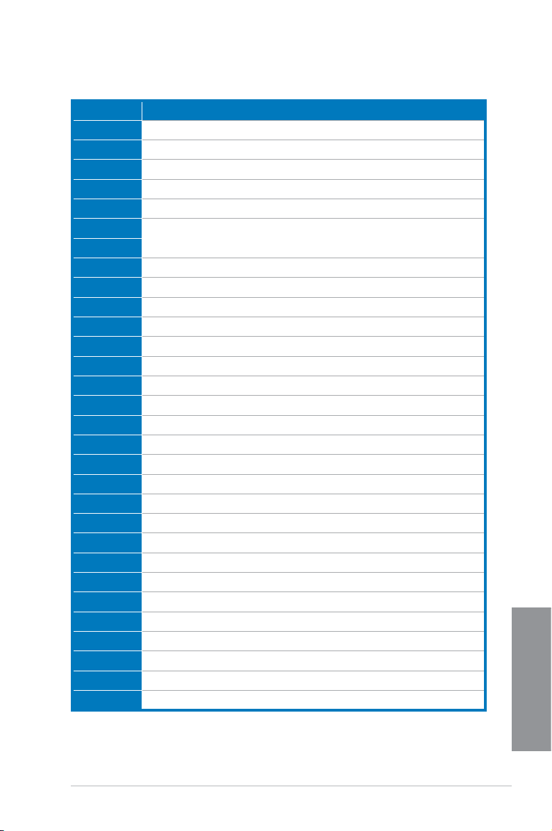
Q-Code table
Code Description
F9 Recovery capsule is not found
FA Invalid recovery capsule
FB – FF Reserved for future AMI error codes
60 DXE Core is started
61 NVRAM initialization
62 Installation of the PCH Runtime Services
63 – 67 CPU DXE initialization is started
68 PCI host bridge initialization
69 System Agent DXE initialization is started
6A System Agent DXE SMM initialization is started
6B – 6F System Agent DXE initialization (System Agent module specic)
70 PCH DXE initialization is started
71 PCH DXE SMM initialization is started
72 PCH devices initialization
73 – 77 PCH DXE Initialization (PCH module specic)
78 ACPI module initialization
79 CSM initialization
7A – 7F Reserved for future AMI DXE codes
90 Boot Device Selection (BDS) phase is started
91 Driver connecting is started
92 PCI Bus initialization is started
93 PCI Bus Hot Plug Controller Initialization
94 PCI Bus Enumeration
95 PCI Bus Request Resources
96 PCI Bus Assign Resources
97 Console Output devices connect
98 Console input devices connect
99 Super IO Initialization
9A USB initialization is started
9B USB Reset
(continued on the next page)
Chapter 1
ASUS MAXIMUS VI HERO
1-35
Page 50

Q-Code table
Code Description
9C USB Detect
9D USB Enable
9E – 9F Reserved for future AMI codes
A0 IDE initialization is started
A1 IDE Reset
A2 IDE Detect
A3 IDE Enable
A4 SCSI initialization is started
A5 SCSI Reset
A6 SCSI Detect
A7 SCSI Enable
A8 Setup Verifying Password
A9 Start of Setup
AA Reserved for ASL (see ASL Status Codes section below)
AB Setup Input Wait
AC Reserved for ASL (see ASL Status Codes section below)
AD Ready To Boot event
AE Legacy Boot event
AF Exit Boot Services event
B0 Runtime Set Virtual Address MAP Begin
B1 Runtime Set Virtual Address MAP End
B2 Legacy Option ROM Initialization
B3 System Reset
B4 USB hot plug
B5 PCI bus hot plug
B6 Clean-up of NVRAM
Chapter 1
B7 Conguration Reset (reset of NVRAM settings)
B8– BF Reserved for future AMI codes
D0 CPU initialization error
D1 System Agent initialization error
(continued on the next page)
1-36
Chapter 1: Product introduction
Page 51
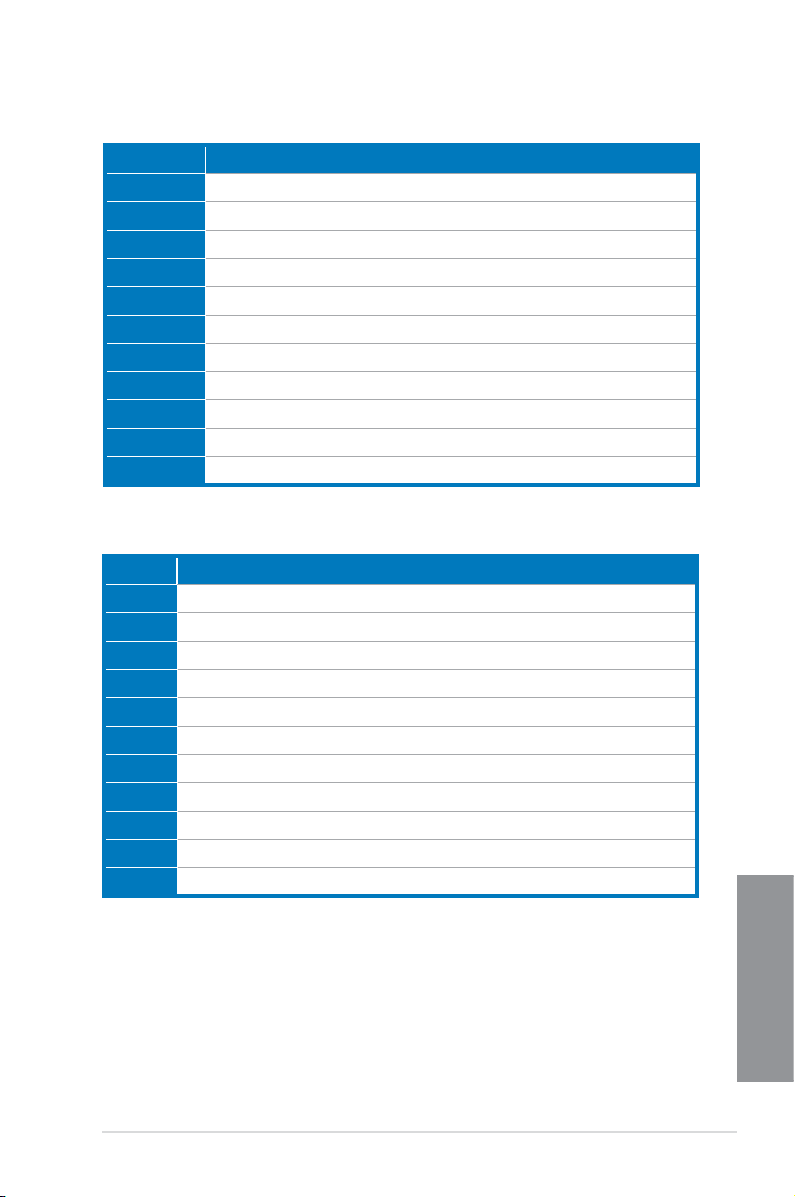
Q-Code table
Code Description
D2 PCH initialization error
D3 Some of the Architectural Protocols are not available
D4 PCI resource allocation error. Out of Resources
D5 No Space for Legacy Option ROM
D6 No Console Output Devices are found
D7 No Console Input Devices are found
D8 Invalid password
D9 Error loading Boot Option (LoadImage returned error)
DA Boot Option is failed (StartImage returned error)
DB Flash update is failed
DC Reset protocol is not available
ACPI/ASL Checkpoints
Code Description
0x01 System is entering S1 sleep state
0x02 System is entering S2 sleep state
0x03 System is entering S3 sleep state
0x04 System is entering S4 sleep state
0x05 System is entering S5 sleep state
0x10 System is waking up from the S1 sleep state
0x20 System is waking up from the S2 sleep state
0x30 System is waking up from the S3 sleep state
0x40 System is waking up from the S4 sleep state
0xAC System has transitioned into ACPI mode. Interrupt controller is in PIC mode.
0xAA System has transitioned into ACPI mode. Interrupt controller is in APIC mode.
ASUS MAXIMUS VI HERO
Chapter 1
1-37
Page 52

1.2.9 Internal connectors
1. Intel® Z87 Serial ATA 6 Gb/s connectors (7-pin SATA6G_1-6 [red])
These connectors connect to Serial ATA 6 Gb/s hard disk drives via Serial ATA 6 Gb/s
signal cables.
If you installed Serial ATA hard disk drives, you can create a RAID 0, 1, 5, and 10
conguration with the Intel® Rapid Storage Technology through the onboard Intel® Z87
chipset.
Chapter 1
1-38
• These connectors are set to [These connectors are set to [AHCI Mode] by default. If you intend to create a Serial
ATA RAID set using these connectors, set the SATA Mode item in the BIOS to [RAID
Mode]. Refer to section 3.6.3 SATA Conguration for details.
• Before creating a RAID set, refer to sectionBefore creating a RAID set, refer to section 5.1 RAID congurations or the manual
bundled in the motherboard support DVD.
• When using NCQ, set the SATA Mode in the BIOS to [When using NCQ, set the SATA Mode in the BIOS to [AHCI Mode]. Refer to section
3.6.3 SATA Conguration for details.
Chapter 1: Product introduction
Page 53

2. ASMedia® Serial ATA 6 Gb/s connectors (7-pin SATA6G_E1/2 [red])
These connectors connect to Serial ATA 6 Gb/s hard disk drives via Serial ATA 6 Gb/s
signal cables.
3. USB 3.0 connector (20-1 pin USB3_12)
This connector allows you to connect a USB 3.0 module for additional USB 3.0 front
or rear panel ports. With an installed USB 3.0 module, you can enjoy all the benets of
USB 3.0 including faster data transfer speeds of up to 5Gbps, faster charging time for
USB-chargeable devices, optimized power efciency, and backward compatibility with
USB 2.0.
• The USB 3.0 module is purchased separately.
• These connectors are based on xHCI specication. We recommend you to install the
related driver to fully use the USB 3.0 ports under Windows® 7.
ASUS MAXIMUS VI HERO
Chapter 1
1-39
Page 54
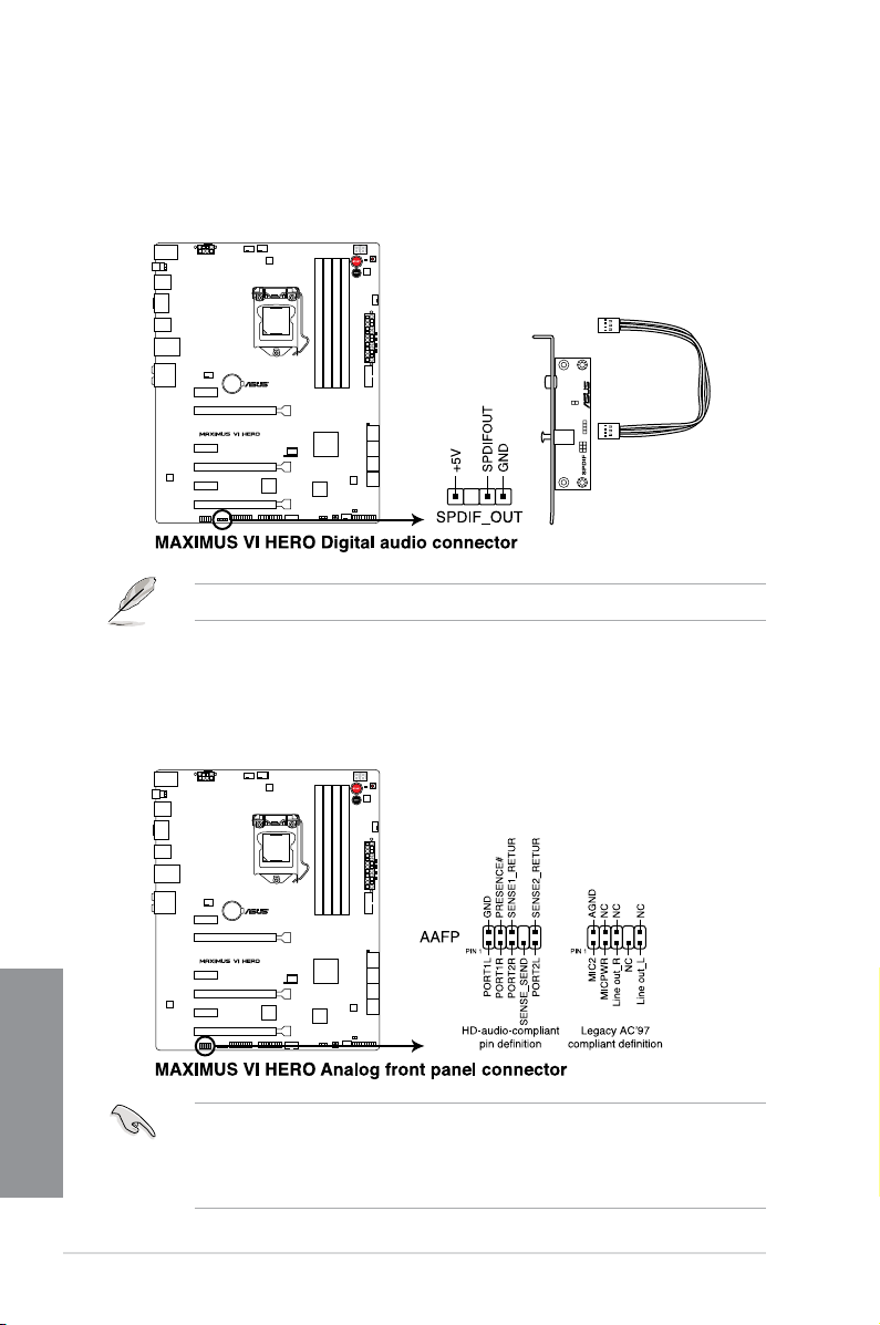
4. Digital audio connector (4-1 pin SPDIF_OUT)
This connector is for an additional Sony/Philips Digital Interface (S/PDIF) port. Connect
the S/PDIF Out module cable to this connector, then install the module to a slot
opening at the back of the system chassis.
The S/PDIF module is purchased separately.
5. Front panel audio connector (10-1 pin AAFP)
This connector is for a chassis-mounted front panel audio I/O module that supports
either HD Audio or legacy AC`97 audio standard. Connect one end of the front panel
audio I/O module cable to this connector.
Chapter 1
1-40
• We recommend that you connect a high-denition front panel audio module to this
connector to avail of the motherboard’s high-denition audio capability.
• If you want to connect a high-denition or an AC’97 front panel audio module to this
connector, set the Front Panel Type item in the BIOS setup to [HD] or [AC97].
Chapter 1: Product introduction
Page 55

6. USB 2.0 connectors (10-1 pin USB1112; USB1314)
These connectors are for USB 2.0 ports. Connect the USB module cable to any of
these connectors, then install the module to a slot opening at the back of the system
chassis. These USB connectors comply with USB 2.0 specication that supports up to
480 MBps connection speed.
Never connect a 1394 cable to the USB connectors. Doing so will damage the
motherboard!
You can connect the front panel USB cable to the ASUS Q-Connector (USB) rst, and then
install the Q-Connector (USB) to the USB connector onboard if your chassis supports front
panel USB ports.
2 x USB2.0 ports (USB1314) at mid-board shares with ROG extension (ROG_EXT) port.
ASUS MAXIMUS VI HERO
Chapter 1
1-41
Page 56

7. CPU, chassis, and optional fan connectors
(4-pin CPU_FAN; 4-pin CPU_OPT; 4-pin CHA_FAN1-3)
Connect the fan cables to the fan connectors on the motherboard, ensuring that the
black wire of each cable matches the ground pin of the connector.
• DO NOT forget to connect the fan cables to the fan connectors. Insufcient air ow
inside the system may damage the motherboard components. These are not jumpers!
Do not place jumper caps on the fan connectors!
• Ensure to fully insert the 4-pin CPU fan cable to the CPU fan connector.
Chapter 1
1-42
The CPU_FAN connector supports the CPU fan of maximum 1A (12 W) fan power.
Chapter 1: Product introduction
Page 57

8. ATX power connectors (24-pin EATXPWR; 8-pin EATX12V)
These connectors are for ATX power supply plugs. The power supply plugs are
designed to t these connectors in only one orientation. Find the proper orientation and
push down rmly until the connectors completely t.
• For a fully congured system, we recommend that you use a power supply unitFor a fully congured system, we recommend that you use a power supply unit
(PSU) that complies with ATX 12 V Specication 2.0 (or later version) and provides a
minimum power of 350 W.
• Do not forget to connect the 4-pin/8-pin EATX12 V power plug. Otherwise, the systemDo not forget to connect the 4-pin/8-pin EATX12 V power plug. Otherwise, the system
will not boot.
• We recommend that you use a PSU with a higher power output when conguring aWe recommend that you use a PSU with a higher power output when conguring a
system with more power-consuming devices. The system may become unstable or
may not boot up if the power is inadequate.
• If you want to use two or more high-end PCI Express x16 cards, use a PSU withIf you want to use two or more high-end PCI Express x16 cards, use a PSU with
1000W power or above to ensure the system stability.
• If you are uncertain about the minimum power supply requirement for your system,If you are uncertain about the minimum power supply requirement for your system,
refer to the Recommended Power Supply Wattage Calculator at http://support.asus.
com/PowerSupplyCalculator/PSCalculator.aspx?SLanguage=en-us for details.
ASUS MAXIMUS VI HERO
Chapter 1
1-43
Page 58

9. System panel connector (20-8 pin PANEL)
This connector supports several chassis-mounted functions.
• System power LED (2-pin PLED)
This 2-pin connector is for the system power LED. Connect the chassis power LED
cable to this connector. The system power LED lights up when you turn on the system
power, and blinks when the system is in sleep mode.
• Hard disk drive activity LED (2-pin HDD_LED)
This 2-pin connector is for the HDD Activity LED. Connect the HDD Activity LED cable
to this connector. The HDD LED lights up or ashes when data is read from or written
to the HDD.
• System warning speaker (4-pin SPEAKER)
This 4-pin connector is for the chassis-mounted system warning speaker. The speaker
allows you to hear system beeps and warnings.
• ATX power button/soft-off button (2-pin PWRSW)
This connector is for the system power button. Pressing the power button turns
the system on or puts the system in sleep or soft-off mode depending on the BIOS
settings. Pressing the power button for more than four seconds while the system is ON
turns the system OFF.
• Reset button (2-pin RESET)
This 2-pin connector is for the chassis-mounted reset button for system reboot without
turning off the system power.
Chapter 1
1-44
Chapter 1: Product introduction
Page 59

10. DirectKey connector (2-pin DRCT)
This connector is for the chassis-mounted button that supports the DirectKey function.
Connect the button cable that supports DirectKey, from the chassis to this connector on
the motherboard.
Ensure that your chassis comes with the extra button cable that supports the DirectKey
feature. Refer to the technical documentation that came with the chassis for details.
ASUS MAXIMUS VI HERO
Chapter 1
1-45
Page 60

11 ROG Extension - ROG_EXT connector (18-1 pin ROG_EXT)
This connector is for the OC Panel and the other ROG device.
• The OC Panel is purchased separately.
• The OC Panel allows you to perform overclocking without going to the BIOS settings,
loading the OS, or using overclocking software utilities.
12. TPM connector (20-1 pin TPM)
This connector supports a Trusted Platform Module (TPM) system, which securely
store keys, digital certicates, passwords and data. A TPM system also helps enhance
the network security, protects digital identities, and ensures platform integrity.
Chapter 1
1-46
Chapter 1: Product introduction
Page 61

Chapter 2: Basic Installation
Basic Installation
2.1 Building your PC system
2.1.1 Motherboard installation
The diagrams in this section are for reference only. The motherboard layout may vary with
models, but the installation steps are the same for all models.
1. Install the ASUS Q-Shield to the chassis rear I/O panel.
2
2. Place the motherboard into the chassis, ensuring that its rear I/O ports are aligned to
the chassis’ rear I/O panel.
ASUS MAXIMUS VI HERO
Chapter 2
2-1
Page 62

3. Place nine screws into the holes indicated by circles to secure the motherboard to the
chassis.
Chapter 2
2-2
DO NOT overtighten the screws! Doing so can damage the motherboard.
Chapter 2: Basic Installation
Page 63

2.1.2 CPU installation
A
B
A
B
C
Ensure that you install the correct CPU designed for LGA1150 socket only. DO NOT install a
CPU designed for LGA1155 and LGA1156 sockets on the LGA1150 socket.
1
2
4
3
5
Chapter 2
ASUS MAXIMUS VI HERO
2-3
Page 64
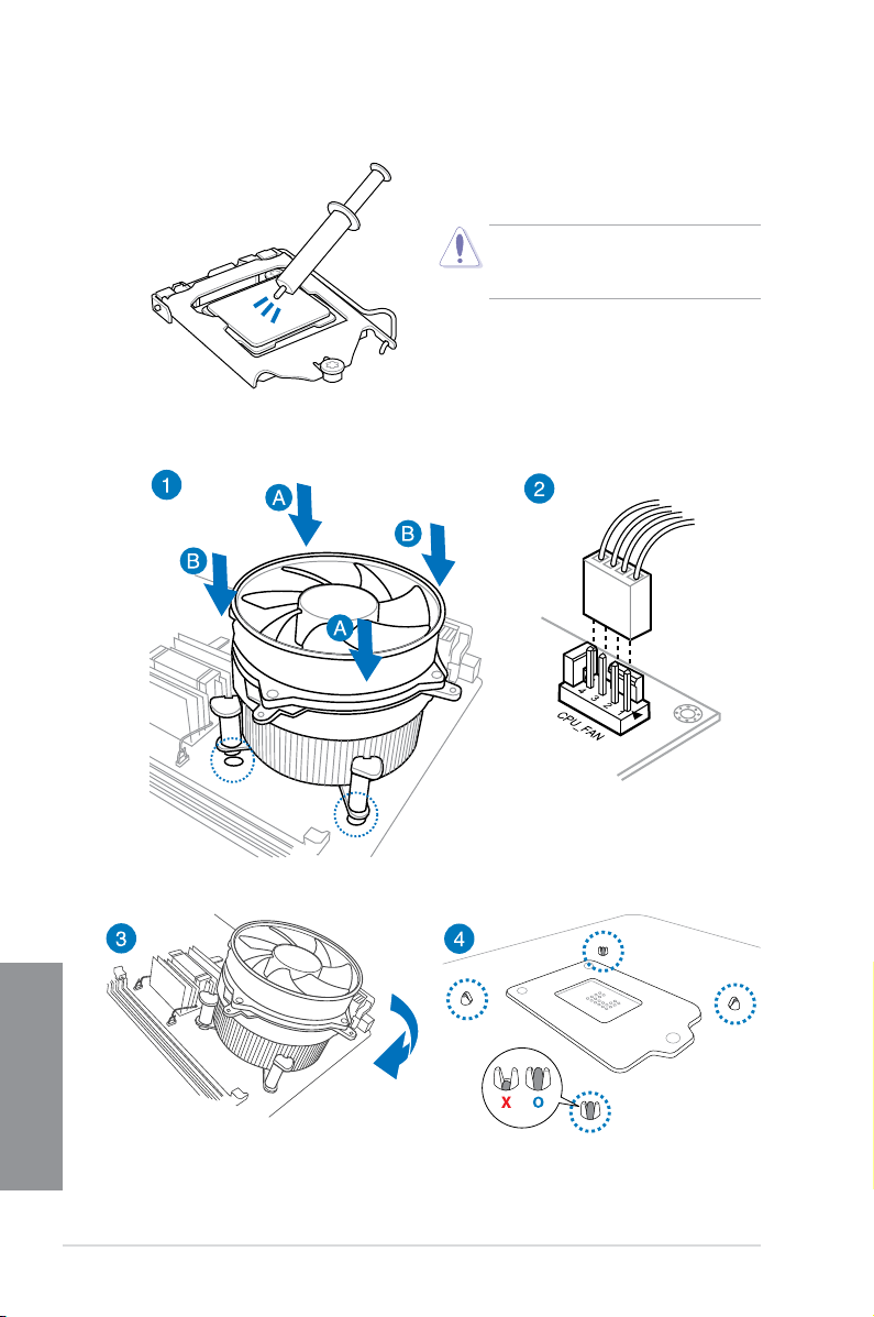
2.1.3 CPU heatsink and fan assembly installation
Apply the Thermal Interface Material to the
CPU heatsink and CPU before you install
the heatsink and fan if necessary.
To install the CPU heatsink and fan assembly
Chapter 2
2-4
Chapter 2: Basic Installation
Page 65

To uninstall the CPU heatsink and fan assembly
ASUS MAXIMUS VI HERO
Chapter 2
2-5
Page 66

2.1.4 DIMM installation
1
2
3
To remove a DIMM
Chapter 2
2-6
B
A
Chapter 2: Basic Installation
Page 67

2.1.5 ATX Power connection
1
2
OR OR
ASUS MAXIMUS VI HERO
Chapter 2
2-7
Page 68

2.1.6 SATA device connection
1
OR
2
Chapter 2
2-8
Chapter 2: Basic Installation
Page 69

2.1.7 Front I/O Connector
To install ASUS Q-Connector
1
2
To install USB 2.0 connector To install front panel audio connector
AAFP
USB 2.0
To install USB 3.0 connector
USB 3.0
ASUS MAXIMUS VI HERO
Chapter 2
2-9
Page 70

2.1.8 Expansion Card installation
To install PCIe x16 cards
Chapter 2
2-10
Chapter 2: Basic Installation
Page 71

2.2 BIOS update utility
USB BIOS Flashback
USB BIOS Flashback allows you to easily update the BIOS without entering the existing
BIOS or operating system. Simply insert a USB storage device to the USB port, press the
USB BIOS Flashback button for three seconds, and the BIOS is updated automatically.
To use USB BIOS Flashback:
1. Download the latest BIOS le from the ASUS websiteDownload the latest BIOS le from the ASUS website
2. Extract and rename the BIOS image le to M6H.CAP.
3. Copy M6H.CAP to the root directory of the USB ash disk drive.
4. Turn off the system and insert the USB storage device to the ROG Connect port.
5. Press the ROG Connect button and release when a ashing light appears, which
indicates that the BIOS Flashback function is enabled.
6. Wait until the light goes out, indicating that the BIOS updating process is completed.
USB BIOS
Flashback button
For more BIOS update utilities in BIOS setup, refer to the section Updating BIOS in
Chapter 3.
Updating BIOS may have risks. If the BIOS program is damaged during the process and
results to the system’s failure to boot up, please contact your local ASUS Service Center.
ASUS MAXIMUS VI HERO
USB BIOS
Flashback port
Chapter 2
2-11
Page 72

2.3 Motherboard rear and audio connections
2.3.1 Rear I/O connection
Rear panel connectors
1. PS/2 Keyboard/Mouse combo portPS/2 Keyboard/Mouse combo port
2. Intel® USB 2.0 port 9 and 10. Intel® USB 2.0 port 10 supports USB BIOS Flashback
and USB Charger+
3. Optical S/PDIF OUT portOptical S/PDIF OUT port
4. Intel® USB 3.0 port 3 and 4
5. LAN (RJ-45) port*LAN (RJ-45) port*
6. IntelIntel® USB 2.0 port 7 and 8
7. USB BIOS Flashback buttonUSB BIOS Flashback button
Chapter 2
8. HDMI port
9. IntelIntel® USB 3.0 port 5 and 6
10. Audio I/O ports**
* and ** : Refer to the tables on the next page for LAN port LEDs, and audio port denitions.
2-12
Chapter 2: Basic Installation
Page 73

• Due to USB 3.0 controller limitation, USB 3.0 devices can only be used under
Windows® OS environment and after the USB 3.0 driver installation.
• USB 3.0 devices can only be used as data storage only.
• We strongly recommend that you connect USB 3.0 devices to USB 3.0 ports for faster
and better performance for your USB 3.0 devices.
• Due to the design of the Intel® 8 series chipset, all USB devices connected to the
USB 2.0 and USB 3.0 ports are controlled by the xHCI controller. Some legacy USB
devices must update their rmware for better compatibility.
* LAN ports LED indications
ACT/LINK
LED
SPEED
LED
Activity Link LED Speed LED
Status Description Status Description
OFF No link OFF 10 Mbps connection
ORANGE Linked ORANGE 100 Mbps connection
LAN port
BLINKING Data activity GREEN 1 Gbps connection
** Audio 2.1, 4.1, 5.1 or 7.1-channel conguration
Port Headset
2.1-channel
Light Blue Line In Line In Line In Line In
Lime Line Out Front Speaker Out Front Speaker Out Front Speaker Out
Pink Mic In Mic In Mic In Mic In
Orange – – Center/Subwoofer Center/Subwoofer
Black
Gray
– Rear Speaker Out Rear Speaker Out Rear Speaker Out
– – – Side Speaker Out
4.1-channel 5.1-channel 7.1-channel
2.3.2 Audio I/O connections
Audio I/O ports
ASUS MAXIMUS VI HERO
Chapter 2
2-13
Page 74

Connect to Headphone and Mic
Connect to Stereo Speakers
Connect to 2.1 channel Speakers
Chapter 2
2-14
Chapter 2: Basic Installation
Page 75
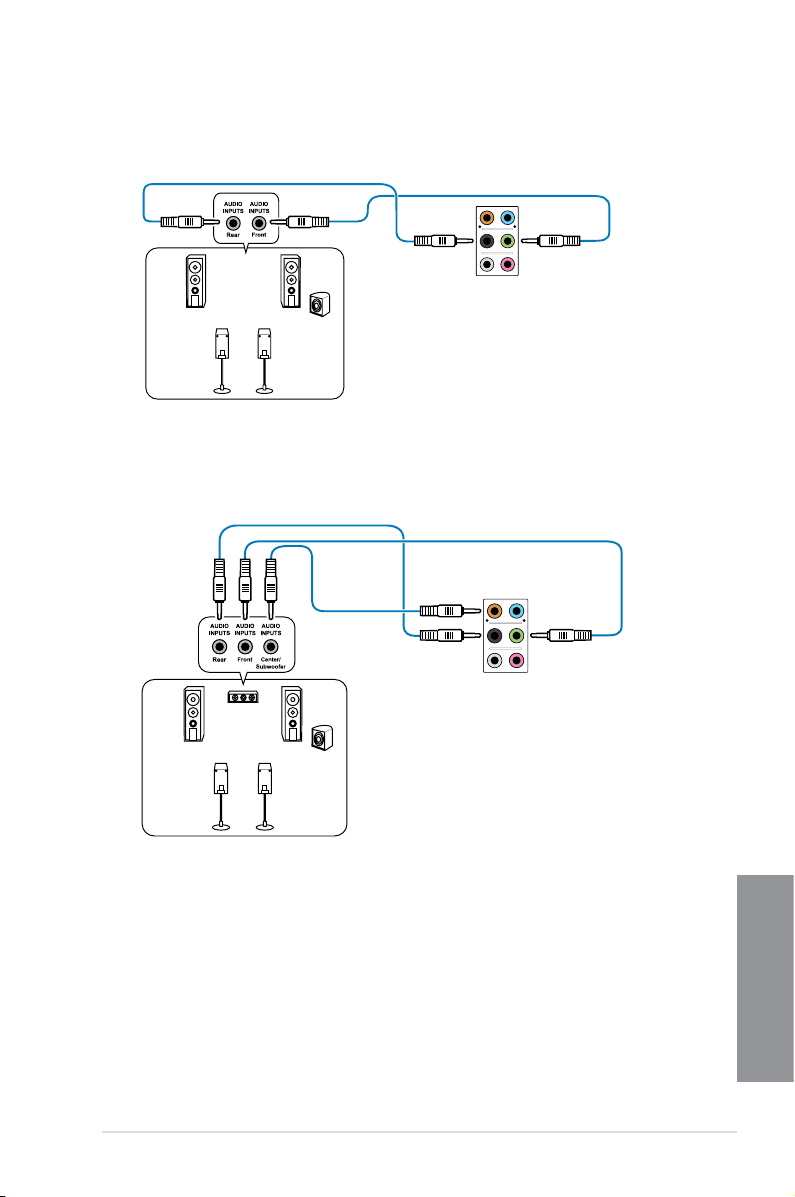
Connect to 4.1 channel Speakers
Connect to 5.1 channel Speakers
ASUS MAXIMUS VI HERO
Chapter 2
2-15
Page 76

Connect to 7.1 channel Speakers
Chapter 2
2-16
Chapter 2: Basic Installation
Page 77

2.4 Starting up for the rst time
1. After making all the connections, replace the system case cover.
2. Ensure that all switches are off.
3. Connect the power cord to the power connector at the back of the system chassis.
4. Connect the power cord to a power outlet that is equipped with a surge protector.
5. Turn on the devices in the following order:
a. Monitor
b. External SCSI devices (starting with the last device on the chain)
c. System power
6. After applying power, the system power LED on the system front panel case lights up.
For systems with ATX power supplies, the system LED lights up when you press the
ATX power button. If your monitor complies with the “green” standards or if it has a
“power standby” feature, the monitor LED may light up or change from orange to green
after the system LED turns on.
The system then runs the power-on self tests (POST). While the tests are running, the
BIOS beeps (refer to the BIOS beep codes table) or additional messages appear on
the screen. If you do not see anything within 30 seconds from the time you turned on
the power, the system may have failed a power-on test. Check the jumper settings and
connections or call your retailer for assistance.
BIOS Beep Description
One short beep VGA detected
One continuous beep followed by two
short beeps then a pause (repeated)
One continuous beep followed by three
short beeps
One continuous beep followed by four
short beeps
Quick boot set to disabled
No keyboard detected
No memory detected
No VGA detected
Hardware component failure
7. At power on, hold down the <Delete> key to enter the BIOS Setup. Follow the
instructions in Chapter 3.
2.5 Turning off the computer
While the system is ON, press the power button for less than four seconds to put the system
on sleep mode or soft-off mode, depending on the BIOS setting. Press the power button
for more than four seconds to let the system enter the soft-off mode regardless of the BIOS
setting.
ASUS MAXIMUS VI HERO
Chapter 2
2-17
Page 78

Chapter 2
2-18
Chapter 2: Basic Installation
Page 79

Chapter 3: BIOS setup
BIOS setup
3
3.1 Knowing BIOS
The new ASUS UEFI BIOS is a Unied Extensible Interface that complies with UEFI
architecture, offering a user-friendly interface that goes beyond the traditional keyboard-
only BIOS controls to enable a more exible and convenient mouse input. You can easily
navigate the new UEFI BIOS with the same smoothness as your operating system. The
term “BIOS” in this user manual refers to “UEFI BIOS” unless otherwise specied.
BIOS (Basic Input and Output System) stores system hardware settings such as storage
device conguration, overclocking settings, advanced power management, and boot
device conguration that are needed for system startup in the motherboard CMOS. In
normal circumstances, the default BIOS settings apply to most conditions to ensure
optimal performance. DO NOT change the default BIOS settings except in the following
circumstances:
q An error message appears on the screen during the system bootup and requests you
to run the BIOS Setup.
q You have installed a new system component that requires further BIOS settings or
update.
Inappropriate BIOS settings may result to instability or boot failure. We strongly
recommend that you change the BIOS settings only with the help of a trained service
personnel.
When downloading or updating the BIOS le, rename it as M6H.CAP for this motherboard.
ASUS MAXIMUS VI HERO
Chapter 3
3-1
Page 80

3.2 BIOS setup program
Use the BIOS Setup to update the BIOS or congure its parameters. The BIOS screen
include navigation keys and brief onscreen help to guide you in using the BIOS Setup
program.
Entering BIOS at startup
To enter BIOS Setup at startup, press <Delete> during the Power-On Self Test (POST). If you
do not press <Delete>, POST continues with its routines.
Entering BIOS Setup after POST
To enter BIOS Setup after POST:
q Press <Ctrl>+<Alt>+<Delete> simultaneously.
q Press the reset button on the system chassis.
q Press the power button to turn the system off then back on. Do this option only if you
failed to enter BIOS Setup using the rst two options.
• The BIOS setup screens shown in this section are for reference purposes only, and
may not exactly match what you see on your screen.
• Ensure that a USB mouse is connected to your motherboard if you want to use the
mouse to control the BIOS setup program.
• If the system becomes unstable after changing any BIOS setting, load the default
settings to ensure system compatibility and stability. Select the Load Optimized
Defaults item under the Exit menu or press hotkey <F5>. See section 3.10 Exit Menu
for details.
• If the system fails to boot after changing any BIOS setting, try to clear the CMOS and
reset the motherboard to the default value. See section 1.2.6 Onboard buttons for
information on how to erase the RTC RAM via the Clear CMOS button.
• The BIOS setup program does not support the bluetooth devices.
BIOS menu screen
The BIOS Setup program can be used under two modes: EZ Mode and Advanced Mode.
You can change modes from the Exit menu or from the Exit/Advanced Mode screen.
Chapter 3
3-2
Chapter 3: BIOS setup
Page 81

3.2.1 EZ Mode
The EZ Mode provides you an overview of the basic system information, and allows you to
select the display language, system performance mode and boot device priority. To access
the Advanced Mode, click Exit/Advanced Mode, then select Advanced Mode or press <F7>
hot key for the advanced BIOS settings.
The default screen for entering the BIOS setup program can be changed. Refer to the
Setup Mode item in section 3.8 Boot menu for details.
Selects the display language of the
BIOS setup program
Displays the CPU/motherboard temperature,
CPU/5V/3.3V/12V voltage output, CPU/chassis/
power fan speed
Displays the selected
shortcut items
Selects the boot device priority
Power Saving mode
Displays the Advanced
mode menus
Normal mode
ASUS Optimal
mode
Click to display all fan
speeds if available
Exits the BIOS setup program without saving
the changes, saves the changes and resets the
system, or enters the Advanced Mode
Boot Menu
Loads optimized default
settings
Displays the system properties of the
selected mode on the right hand side
• The boot device options vary depending on the devices you installed to the system.
• TheThe Boot Menu (F8) button is available only when the boot device is installed to the
system.
ASUS MAXIMUS VI HERO
Chapter 3
3-3
Page 82

3.2.2 Advanced Mode
The Advanced Mode provides advanced options for experienced end-users to congure
the BIOS settings. The gure below shows an example of the Advanced Mode. Refer to the
following sections for the detailed congurations.
To access the Advanced Mode, click Exit, then select Advanced Mode or press F7 hotkey.
Menu items
Submenu item
Menu bar
Conguration elds
Pop-up window
Scroll bar
Menu bar
The menu bar on top of the screen has the following main items:
General help
Navigation keys
My Favorites For saving the frequently-used system settings and conguration.
Chapter 3
Extreme Tweaker For changing the overclocking settings
Main For changing the basic system conguration
Advanced For changing the advanced system settings
Monitor
Boot For changing the system boot conguration
Tool For conguring options for special functions
Exit For selecting the exit options and loading default settings
3-4
For displaying the system temperature, power status, and changing
the fan settings.
Chapter 3: BIOS setup
Page 83

Menu items
The highlighted item on the menu bar displays the specic items for that menu. For example,
selecting Main shows the Main menu items.
The other items (My Favorites, Ai Tweaker, Advanced, Monitor, Boot, Tool, and Exit) on the
menu bar have their respective menu items.
Back button
This button appears when entering a submenu. Press <Esc> or use the USB mouse to click
this button to return to the previous menu screen.
Submenu items
A greater than sign (>) before each item on any menu screen means that the item has a
submenu. To display the submenu, select the item and press <Enter>.
Pop-up window
Select a menu item and press <Enter> to display a pop-up window with the conguration
options for that item.
Scroll bar
A scroll bar appears on the right side of a menu screen when there are items that do not t on
the screen. Press the Up/Down arrow keys or <Page Up> / <Page Down> keys to display the
other items on the screen.
Navigation keys
At the bottom right corner of the menu screen are the navigation keys for the BIOS setup
program. Use the navigation keys to select items in the menu and change the settings.
If you delete all shortcut items from the F3: Shortcut list, the default shortcut items will
reappear after your next startup.
General help
At the top right corner of the menu screen is a brief description of the selected item. Use
<F12> key to capture the BIOS screen and save it to the removable storage device.
Conguration elds
These elds show the values for the menu items. If an item is user-congurable, you can
change the value of the eld opposite the item. You cannot select an item that is not
user-congurable.
A congurable eld is highlighted when selected. To change the value of a eld, select it and
press <Enter> to display a list of options.
Quick Note button
This button allows you to enter notes of the activities that you have done in BIOS.
• The Quick Note function does not support the following keyboard functions: delete,
cut, copy and paste.
• You can only use the alphanumeric characters to enter your notes.
ASUS MAXIMUS VI HERO
Chapter 3
3-5
Page 84

Last Modied button
This button shows the items that you last modied and saved in BIOS Setup.
3.3 My Favorites
MyFavorites is your personal space where you can easily save and access your favorite
BIOS items.
Adding items to My Favorites
To add frequently-used BIOS items to My Favorites:
1. Use the arrow keys to select an item that you want to add. When using a mouse, hover
the pointer to the item.
2. Press <F4> on your keyboard or right-click on your mouse to add the item to My
Favorites page.
Chapter 3
3-6
You cannot add the following items to My Favorites:
• Items with submenu options
• User-congurable items such as language and boot device order
• Conguration items such as Memory SPD Information, system time and date
Chapter 3: BIOS setup
Page 85
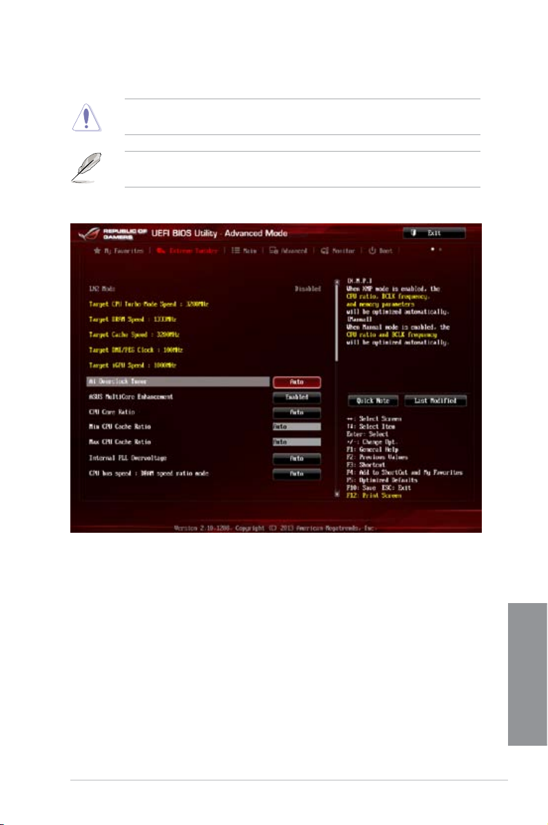
3.4 Extreme Tweaker menu
The Extreme Tweaker menu items allow you to congure overclocking-related items.
Be cautious when changing the settings of the Extreme Tweaker menu items. Incorrect eld
values can cause the system to malfunction
The conguration options for this section vary depending on the CPU and DIMM model you
installed on the motherboard.
Scroll down to display other BIOS items.
ASUS MAXIMUS VI HERO
Chapter 3
3-7
Page 86

Ai Overclock Tuner [Auto]
Allows you to select the CPU overclocking options to achieve the desired CPU internal
frequency. Select any of these preset overclocking conguration options:
[Auto] Loads the optimal settings for the system.
[Manual] Allows you to individually set overclocking parameters.
[X.M.P.] If you install memory modules supporting the eXtreme Memory Prole
(X.M.P.) Technology, choose this item to set the proles supported by your
memory modules for optimizing the system performance.
The [X.M.P.] conguration option appears only when you install memory modules
supporting the eXtreme Memory Prole(X.M.P.) Technology.
ASUS MultiCore Enhancement [Enabled]
[Enabled] Default is set to [Enabled] for maximum performance under XMP/Manual/
[Disabled] Allows you to set to default core ratio settings.
User-dened memory frequency mode.
CPU Core Ratio [Auto]
Allows you to set the CPU ratio and sync automatically, per core or all cores.
Conguration options: [Auto] [Sync All Cores] [Per Core]
When the CPU Core Ratio is set to [Auto], the following item appears:
Min CPU Cache Ratio [Auto]
Allows you to set the minimum possible ratio on the Uncore part of the processor. Use the
<+> or <-> keys to adjust the value. The values depend on the CPU installed.
Max CPU Cache Ratio [Auto]
Allows you to set the maximum possible ratio on the Uncore part of the processor. Use the
<+> or <-> keys to adjust the value. The values depend on the CPU installed.
Chapter 3
3-8
When the CPU Core Ratio is set to [Synch All Cores], the following item appears.
1-Core Ratio Limit [Auto]
Select [Auto] to apply the CPU default Turbo Ratio setting or manually
assign a 1-Core Limit value that must be higher than or equal to the 2-Core
Ratio Limit.
Chapter 3: BIOS setup
Page 87

When the CPU Core Ratio is set to [Per Core], the following item appears:
1-Core Ratio Limit [Auto]
Select [Auto] to apply the CPU default Turbo Ratio setting or manually
assign a 1-Core Limit value that must be higher than or equal to the 2-Core
Ratio Limit.
2-Core Ratio Limit [Auto]
Select [Auto] to apply the CPU default Turbo Ratio setting or manually
assign a 2-Core Limit value that must be higher than or equal to the 3-Core
Ratio Limit.
3-Core Ratio Limit [Auto]
Select [Auto] to apply the CPU default Turbo Ratio setting or manually
assign a 3-Core Limit value that must be higher than or equal to the 4-Core
Ratio Limit.
4-Core Ratio Limit [Auto]
Select [Auto] to apply the CPU default Turbo Ratio setting or manually
assign a 4-Core Limit value that must be higher than or equal to the 3-Core
Ratio Limit.
If you assign a value for more Core Ratio Limit, do not set the less Core Ratio Limit to
[Auto].
Internal PLL Overvoltage [Auto]
Allows you to enable the internal PLL voltage for K-SKU CPUs to get the extreme
overclocking capability.
Conguration options: [Auto] [Enabled] [Disabled]
CPU bus speed : DRAM speed ratio mode [Auto]
Allows you to set the CPU bus speed to DRAM speed ratio mode.
[Auto] The DRAM speed is set to its optimized settings.
[100:100] The CPU bus speed to DRAM speed ratio is set to 100:100.
[100:133] The CPU bus speed to DRAM speed ratio is set to 100:133.
Memory Frequency [Auto]
Allows you to set the memory operating frequency. The conguration options vary with the
BCLK/CPU Strap Frequency item settings.
ASUS MAXIMUS VI HERO
Chapter 3
3-9
Page 88

Xtreme Tweaking [Disabled]
This item may help improve some benchmarks performance.
Conguration options: [Enabled] [Disabled]
CPU Graphics Max. Ratio [Auto]
Allows you to automatically optimize the CPU Graphics Ratio or manually set a value for an
optimal CPU Graphics Ratio. Use the <+> or <-> keys to adjust the CPU graphics ratio. The
minimum value depends on the installed CPU.
CPU Level Up [Auto]
Allows you to select a CPU level, and the related parameters will be automatically adjusted
according to the selected CPU level.
Conguration options: [Auto] [4.600G] [4.400G] [4.200G] [4.400G] [4.200G]
EPU Power Saving Mode [Disabled]
Allows you to enable or disable the EPU power saving function.
Conguration options: [Disabled] [Enabled]
DRAM Timing Control
The subitems in this menu allow you to set the DRAM timing control features. Use the <+>
and <-> keys to adjust the value. To restore the default setting, type [auto] using the keyboard
and press the <Enter> key.
Primary Timings
DRAM CAS# Latency [Auto]
Conguration options: [Auto] [1] – [31]
DRAM RAS# to CAS# Delay [Auto]
Conguration options: [Auto] [1] – [31]
DRAM RAS# PRE Time [Auto]
Conguration options: [Auto] [1] – [31]
DRAM RAS# ACT Time [Auto]
Conguration options: [Auto] [1] – [63]
DRAM COMMAND Rate [Auto]
Conguration options: [Auto] [1] – [3]
Chapter 3
3-10
Chapter 3: BIOS setup
Page 89

Secondary Timings
DRAM RAS# to RAS# Delay [Auto]
Conguration options: [Auto] [1] – [15]
DRAM REF Cycle Time [Auto]
Conguration options: [Auto] [1] – [511]
DRAM Refresh Interval [Auto]
Conguration options: [Auto] [1] – [65535]
DRAM WRITE Recovery Time [Auto]
Conguration options: [Auto] [1] – [16]
DRAM READ to PRE Time [Auto]
Conguration options: [Auto] [1] – [15]
DRAM FOUR ACT WIN Time [Auto]
Conguration options: [Auto] [1] – [255]
DRAM WRITE to READ Delay [Auto]
Conguration options: [Auto] [1] – [15]
DRAM CKE Minimum pulse width [Auto]
Conguration options: [Auto] [1] – [15]
DRAM CAS# Write Latency [Auto]
Conguration options: [Auto] [1] – [31]
RTL IOL control
DRAM RTL Initial Value [Auto]
Conguration options: [Auto] [1] - [63]
DRAM RTL (CHA_R0D0) [Auto]
Conguration options: [Auto] [1] - [63]
DRAM RTL (CHA_R0D1) [Auto]
Conguration options: [Auto] [1] - [63]
DRAM RTL (CHA_R1D0) [Auto]
Conguration options: [Auto] [1] - [63]
DRAM RTL (CHA_R1D1) [Auto]
Conguration options: [Auto] [1] - [63]
DRAM RTL (CHB_R0D0) [Auto]
Conguration options: [Auto] [1] - [63]
DRAM RTL (CHB_R0D1) [Auto]
Conguration options: [Auto] [1] - [63]
DRAM RTL (CHB_R1D0) [Auto]
Conguration options: [Auto] [1] - [63]
ASUS MAXIMUS VI HERO
Chapter 3
3-11
Page 90

Third Timings
tRDRD [Auto]
Conguration options: [Auto] [1] – [7]
tRDRD_dr [Auto]
Conguration options: [Auto] [1] – [15]
tRDRD_dd [Auto]
Conguration options: [Auto] [1] – [15]
tWRRD [Auto]
Conguration options: [Auto] [1] – [63]
tWRRD_dr [Auto]
Conguration options: [Auto] [1] – [15]
tWRRD_dd [Auto]
Conguration options: [Auto] [1] – [15]
tWRWR [Auto]
Conguration options: [Auto] [1] – [7]
Chapter 3
tWRWR_dr [Auto]
Conguration options: [Auto] [1] – [15]
tWRWR_dd [Auto]
Conguration options: [Auto] [1] – [15]
Dec_WRD
Conguration options: [Auto] [0] – [1]
DRAM RTL (CHB_R1D1) [Auto]
Conguration options: [Auto] [1] - [63]
DRAM IO-L (CHA_R0D0) [Auto]
Conguration options: [Auto] [1] - [15]
DRAM IO-L (CHA_R0D1) [Auto]
Conguration options: [Auto] [1] - [15]
DRAM IO-L (CHA_R1D0) [Auto]
Conguration options: [Auto] [1] - [15]
DRAM IO-L (CHA_R1D1) [Auto]
Conguration options: [Auto] [1] - [15]
DRAM IO-L (CHB_R0D0) [Auto]
Conguration options: [Auto] [1] - [15]
DRAM IO-L (CHB_R0D1) [Auto]
Conguration options: [Auto] [1] - [15]
DRAM IO-L (CHB_R1D0) [Auto]
Conguration options: [Auto] [1] - [15]
DRAM IO-L (CHB_R1D1) [Auto]
Conguration options: [Auto] [1] - [15]
3-12
Chapter 3: BIOS setup
Page 91

tRDWR [Auto]
Conguration options: [Auto] [1] – [31]
tRDWR_dr [Auto]
Conguration options: [Auto] [1] – [31]
tRDWR_dd [Auto]
Conguration options: [Auto] [1] – [31]
MISC
MRC Fast Boot [Auto]
Allows you to enable, disable or automatically set the MRC fast boot.
Conguration options: [Auto] [Enabled] [Disabled]
DRAM CLK Period [Auto]
Conguration options: [Auto] [1] – [14]
Channel A DIMM Control [Enable Bot...]
Allows you to enable or disable the Channel A DIMM slots with the following
conguration options: [Enable Both DIMMS] [Disable DIMM0] [Disable DIMM1]
[Disable Both DIMMS]
Channel B DIMM Control [Enable Bot...]
Allows you to enable or disable the Channel B DIMM slots with the following
conguration options: [Enable Both DIMMS] [Disable DIMM0] [Disable DIMM1]
[Disable Both DIMMS]
Scrambler Setting [Optimized ...]
Set this item to [Optimized (ASUS)] to enhance system stability.
Conguration options: [Optimized (ASUS)] [Default (MRC)]
DQ Sense Amplifier [Auto]
Reducing usually helps overclocking and over-voltage.
Conguration options: [Auto] [+16] – [-16]
DQS Sense Amplifier [Auto]
Reducing usually helps overclocking and over-voltage.
Conguration options: [Auto] [+16] – [-16]
CMD Sense Amplifier [Auto]
Reducing usually helps overclocking and over-voltage.
Conguration options: [Auto] [+16] – [-16]
GPU.DIMM Post
Automatically detects and displays the information about the devices or memory installed on
the PCIe and DIMM slots. The eld shows N/A if there are no devices installed on the slots.
ASUS MAXIMUS VI HERO
Chapter 3
3-13
Page 92

DIGI+ Power Control
CPU Load-Line Calibration [Auto]
Load-line is dened by Intel® VRM specication and affects CPU power voltage. The
CPU working voltage will decrease proportionally to CPU loading. Higher load-line
calibration could get higher voltage and good overclocking performance but increases
the CPU and VRM thermal conditions.
Select from Level 1 to Level 8 to adjust CPU power voltage from 0% to 100%.
• The actual performance boost may vary depending on your CPU specication.
• DO NOT remove the thermal module. The thermal conditions must be monitored.
CPU Voltage Frequency [Auto]
Switching frequency affects the VRM transient response and the thermal component
conditions. Higher frequency gets quicker transient response.
Conguration options: [Auto] [Manual]
DO NOT remove the thermal module when setting this item to [Manual]. The thermal
conditions should be monitored.
The following items appear only when you set the CPU Voltage Frequency to [Auto].
VRM Spread Spectrum [Disabled]
Enable the VRM Spread Spectrum to enhance system stability.
Conguration options: [Disabled] [Enabled]
Active Frequency Mode [Disabled]
Enable the Active Frequency Mode for an enhanced power saving
condition.
Conguration options: [Disabled] [Enabled]
Chapter 3
3-14
The following item appears only when you set the CPU Voltage Frequency to [Manual].
CPU Fixed Frequency [XXX]
This item allows you to set a xed CPU frequency. Use the <+> or <-> keys
to adjust the valinterval.
VCCIN MOS Volt Control [Auto]
This is the driving voltage for the MOSFET on the VCCIN Rail.
Conguration options: [Auto] [Manual] [Active VGD]
Chapter 3: BIOS setup
Page 93

CPU Power Phase Control [Auto]
Allows you to set the power phase control of the CPU.
[Standard] Set the phase control based on the CPU command.
[Optimized] Set the ASUS optimized phase tuning prole.
[Extreme] Set the full phase mode
[Manual
Adjustment]
Set manually to a faster phase response to increase system
performance or to slower phase response to increase DRAM power
efciency.
DO NOT remove the thermal module when setting this item to [Extreme] and [Manual
Adjustment]. The thermal conditions should be monitored.
The following item appears only when you set the CPU Power Phase Control to [Manual
Adjustment].
Manual Adjustment [Fast]
Allows you to set a response for the CPU power phase control.
Conguration options: [Ultra Fast] [Fast] [Medium] [Regular]
CPU Power Duty Control [T.Probe]
DIGI + VRM Duty Control adjusts the current of every VRM phase and the thermal
conditions of every phase component.
[T. Probe] Select to maintain the VRM thermal balance.
[Extreme] Select to maintain the current VRM balance.
DO NOT remove the thermal module. The thermal conditions should be monitored.
CPU Current Capability [Auto]
DIGI + VRM CPU Current Capability provides wider total power range for overclocking.
A higher value setting gets higher VRM power consumption delivery and extends the
overclocking frequency range simultaneously.
Conguration options: [Auto] [100%] [110%] [120%] [130%] [140%]
Choose a higher value when overclocking or under a high CPU loading for extra power
support.
ASUS MAXIMUS VI HERO
Chapter 3
3-15
Page 94

CPU Power Thermal Control [130]
A higher temperature brings a wider CPU power thermal range and extends the
overclocking tolerance to enlarge the O.C. potential. Use the <+> and <-> keys to
adjust the value. The values range from 130 to 151.
DO NOT remove the thermal module. The thermal conditions should be monitored.
CPU Input Boot Voltage [Auto]
VCCIN for the CPU right at boot. Conguration options: [Auto] [0.800] – [2.440V]
DRAM Current Capability [100%]
A higher value brings a wider total power range and extends the overclocking range
simultaneously.
Conguration options: [100%] [110%] [120%] [130%]
DRAM Voltage Frequency [Auto]
Allows you to adjust the DRAM switching frequency. Assign a xed high DRAM
frequency to increase the overclocking range or a low DRAM frequency for a better
system stability.
Conguration options: [Auto] [Manual]
The following item appears only when you set set the DRAM Frequency Mode item to
[Manual].
DRAM Fixed Frequency Mode [300]
Allows you to set a xed DRAM frequency. Use the <+> or <-> keys to
adjust the value. The values range from 300kHz to 500kHz with a 10kHz
interval.
DRAM Power Phase Control [Auto]
Allows you to set the power phase control of the DRAM.
[Auto] Allows you to set the Auto mode.
[Optimized] Allows you to set the ASUS optimized phase tuning prole.
[Extreme] Allows you to set the full phase mode.
Chapter 3
3-16
Chapter 3: BIOS setup
Page 95

Tweakers’ Paradise
The subitems in this menu allow you to set the CPU ratio and features.
BCLK Tuning
VCCIN Shadow Voltage [Auto]
Pseudo Voltage for VCCIN. Conguration options: [Auto] [0.800] – [2.440V]
Termination Anti-Aliasing [Auto]
Termination Anti-Aliasing can be enabled to smooth out the change of the PLL
Termination Voltage, which may sometimes help to yield a better O.C. result..
Conguration options: [Auto] [Disabled] [Enabled]
Initial PLL Termination Voltage [Auto]
Initial Voltage at which CPU BCLKs are terminated. Maintaining a level close to CPU
Input Voltage will help BCLK Overclock.
Conguration options: [Auto] [0.0000] - [3.0000]
PLL Termination Reset Voltage [Auto]
PLL Termination Reset Voltage. Conguration options: [Auto] [0.0000] - [3.0000]
Eventual PLL Termination Voltage [Auto]
Eventual PLL Termination Voltage. Conguration options: [Auto] [0.0000] - [3.0000][Auto] [0.0000] - [3.0000]
ICC Ringback Canceller [Auto]
ICC Ringback Canceller can be used to control the noise level at the Integrated Clock
Controller.
[Enable] to allow better High DMI Frequency O.C.
[Disable] to allow better Low DMI Frequency O.C.
Clock Crossing VBoot [Auto]
The instantaneous voltage value when the rising edge of BCLK DN is equal to the
falling edge of the BCLK DP. Conguration options: [Auto] [0.1000] - [1.9000]
Clock Crossing Reset Voltage [Auto]
The instantaneous voltage value when the rising edge of BCLK DN is equal to the
falling edge of the BCLK DP. Conguration options: [Auto] [0.1000] - [1.9000]
Clock Crossing Voltage [Auto]
The instantaneous voltage value when the rising edge of BCLK DN is equal to the
falling edge of the BCLK DP. Conguration options: [Auto] [0.1000] - [1.9000]
DMI Gen 2 [Auto]
Allows you to enable or disable DMI Gen 2. Auto means Enabled. Conguration
options: [Auto] [Enabled] [Disabled]
DMI De-emphasis Control [-6 dB]
Congure De-emphasis control on DMI. Conguration options: [-6 dB] [-3.5 db]
ASUS MAXIMUS VI HERO
Chapter 3
3-17
Page 96

PCIE Tuning
Internal Graphics [Auto]
Keep IGD enabled based on setup options.
Conguration options: [Auto] [Disabled] [Enabled]
CPU Power Management
The subitems in this menu allow you to set the CPU ratio and features.
Enhanced Intel SpeedStep Technology [Enabled]
Allows the operating system to dynamically adjust the processor voltage and cores
frequency to decrease the average power consumption and decrease average heat
production.
Conguration options: [Enabled] [Disabled]
Turbo Mode [Enabled]
Allows you to enable your processor cores to run faster than the base operating
frequency when it is below power, current and specication limit.
Conguration options: [Disabled] [Enabled]
The following items appear only when you set the Turbo Mode to [Enabled].
Turbo Mode Parameters
Long Duration Package Power Limit [Auto]
Allows you to limit the Turbo Ratio’s time duration thay exceeds the TDP
(Thermal Design Power) for maximum performance. Use the <+> and <->
keys to adjust the value. The values range from 1W to 4096W.
Package Power Time Window [Auto]
Also known as Power Limit 1, and allows you to maintain the time window
for Turbo Ratio over TDP (Thermal Design Power). Use the <+> and <->
keys to adjust the value. The values range from 1 second to 127 seconds.
Short Duration Package Power Limit [Auto]
Also known as Power Limit 2, and allows you to provide rapid protection
when the package power exceeds the Power Limit 1. Use the <+> and <->
keys to adjust the value. The values range from 1W to 4096W.
CPU Integrated VR Current Limit [Auto]
Allows you to set a higher current limit to prevent frequency and power
throttling when overclocking. Use the <+> and <-> keys to adjust the value.
The values range from 0.125 to 1023.875 with a 0.125 interval.
Chapter 3
3-18
CPU Integrated VR Current Limit appear only when you set the Turbo Mode to [Disabled].
CPU Internal Power Switching Frequency
Frequency Tuning Mode [Auto]
Allows you to increase or decrease the switching frequency of the internal
regulator. Decrease to help consume less power or increase to help voltage
stability. When this item is set to [+] or [-], the Frequency Tuning Offset
appears and allows you to set its value from 0% to 6%.
Chapter 3: BIOS setup
Page 97

CPU Internal Power Fault Control
Thermal Feedback [Auto]
Allows the CPU to take precautionary actions when the thermal conditions
of the external regulator exceeds the threshold.
Conguration options: [Auto] [Disabled] [Enabled]
CPU Integrated VR Fault Management [Auto]
Allows you to prevent tripping the Fully Integrated Voltage Regulator when
doing over-voltage. Conguration options: [Auto] [Disabled] [Enabled]
We recommend to set this item to [Disable] when overclocking.
CPU Internal Power Conguration
CPU Integrated VR Efciency Management [Auto]
Allows you to improve power saving when the processor is in low power
state. Disable this item to make the Fully Integrated Voltage Regulator work
in high performance at all times.
Conguration options: [Auto] [High Performance] [Balanced]
Power Decay Mode [Auto]
Allows you to enable this item to improve the power saving on the Fully
Integrated Voltage Regulator as the processor goes into low current state.
Conguration options: [Auto] [Disabled] [Enabled]
Idle Power-in Response [Auto]
Allows you to set the slew rate for the Fully Integrated Voltage Regulator as
it enters manual override mode.
Conguration options: [Auto] [Regular] [Fast]
Idle Power-out Response [Auto]
Allows you to set the slew rate for the Fully Integrated Voltage Regulator as
it exits manual override mode.
Conguration options: [Auto] [Regular] [Fast]
Power Current Slope [Auto]
Allows you to adjust the gradient of the high-speed active phase current
balance during load transients to eliminate current imbalance, resulting
from a load current oscillating near the switching frequency.
Conguration options: [Auto] [LEVEL -4] - [LEVEL 4]
Power Current Offset [Auto]
Allows you to increase or decrease the output current sensed by the CPU.
It nds the balance between optimal regulating while staying below the
current threshold.
Conguration options: [Auto] [100%] [87.5%] [75.0%] [62.5%] [50.0%]
[37.5%] [25.0%] [12.5%] [0%] [-12.5%] [-25.0%] [-37.5%] [-50.0%] [-62.5%]
[-75.0%] [-87.5%] [-100%]
ASUS MAXIMUS VI HERO
Chapter 3
3-19
Page 98

Power Fast Ramp Response [Auto]
Allows you to increase to enhance the response of the voltage regulator
during the load transient.
Conguration options: [Auto] [0.00] - [1.50]
CPU Internal Power Saving Control
Power Saving Level 1 Threshold [Auto]
Lower value provides sufcient overclocking tolerance to enlarge the
overclocking potential. Higher value provides better power-saving condition.
Use <+> or <-> key to adjust the value. The values range from 0A to 80A at
1Amp increment.
Power Saving Level 2 Threshold [Auto]
Lower value provides sufcient overclocking tolerance to enlarge the
overclocking potential. Higher value provides better power-saving condition.
Use <+> or <-> key to adjust the value. The values range from 0A to 50A at
1Amp increment.
Power Saving Level 3 Threshold [Auto]
Lower value provides sufcient overclocking tolerance to enlarge the
overclocking potential. Higher value provides better power-saving condition.
Use <+> or <-> key to adjust the value. The values range from 0A to 30A at
1Amp increment.
CPU Core Voltage [Auto]
Congures the amount of Voltage fed to the Cores of the processor. Increase when
increasing Core Frequency. Use <+> or <-> key to adjust the value. The values range from
1.050000V to 2.200000V at 0.003125V increment. Confuration options: [Auto]
[Manual Mode] [Offset Mode] [Adaptive Mode]
CPU Core Voltage Override [Auto]
Use<+> or <-> key to adjust the value. The values range from 0.001V to 1.920V at 0.001V
increment. Confuration options: [Auto] [Manual Mode] [Offset Mode] [Adaptive Mode]
Offset Mode Sign [+]
CPU Core Voltage Offset [Auto]
Use<+> or <-> key to adjust the value. The values range from 0.001V to 0.999V at
0.001V increment. Confifuration options: [Auto] [Manual Mode] [Offset Mode]
[Adaptive Mode]
Chapter 3
Additional Turbo Mode CPU Core Voltage [Auto]
The values range from 0.001V to 0.1920V at 0.001V increment. Confuration options: [Auto]
[Manual Mode] [Offset Mode] [Adaptive Mode]
3-20
Appear only when you set the CPU Core Voltage to [Manual Mode].
Appear only when you set the CPU Core Voltage to [Offset/ Adaptive Mode].
Appear only when you set the CPU Core Voltage to [Adaptive Mode].
Chapter 3: BIOS setup
Page 99

CPU Cache Voltage [Auto]
Congures the amount of Voltage fed to the UNCore of the processor including it is cache.
Increase when increasing CPU Cache Frequency. Use <+> or <-> key to adjust the value.
The values range from -0.999V to 0.999V at 0.001V increment.
CPU Graphics Voltage [Auto]
Congures the amount of Voltage fed to the onboard graphics unit on the processor. Increase
when increasing IGPU Frequency. Use <+> or <-> key to adjust the value. The values range
from -0.999V to 0.999V at 0.001V increment.
CPU System Agent Voltage Offset Mode Sign [+]
Congures the amount of Voltage offset applied to the System Agent of the processor
including it is PCIE Controller and Power Control Unit. Increase when increasing DRAM
Frequency. Use <+> or <-> key to adjust the value.
CPU System Agent Voltage Offset [Auto]
The values range from -0.999V to 0.999V at 0.001V increment.
CPU Analog I/O Voltage Offset Mode Sign [+]
Congures the amount of Voltage offset applied for the Analog portion of the I/O on the
processor. Increase when increasing DRAM Frequency. Use <+> or <-> key to adjust the
value.
CPU Analog I/O Voltage Offset [Auto]
The values range from -0.999V to 0.999V at 0.001V increment.
CPU Digital I/O Voltage Offset Mode Sign [+]
Congures the amount of Voltage offset applied for the Digital portion of the I/O on the
processor. Increase when increasing DRAM Frequency. Use <+> or <-> key to adjust the
value.
CPU Digital I/O Voltage Offset [Auto]
The values range from -0.999V to 0.999V at 0.001V increment.
Appear only when you set the CPU Core Voltage to [Auto].
SVID Support [Auto]
Disabling SVID Support stops the processor from communicating with the external Voltage
Regulator. Recommend disabling when overclocking. Conguration options: [Auto] [Enabled]
[Disabled]
Initial CPU Input Voltage [Auto]
Allows you to set the CPU Input Voltage. Use <+> or <-> key to adjust the value. The values
range from 0.800V to 2.440V at 0.010V increment.
ASUS MAXIMUS VI HERO
Chapter 3
3-21
Page 100

Eventual CPU Input Voltage [Auto]
Allows you to set the Eventual CPU Input Voltage. Use <+> or <-> key to adjust the value.
The values range from 0.800V to 2.440V at 0.010V increment.
DRAM Voltage [Auto]
Allows you to set the voltage for the system memory. Use <+> or <-> key to adjust the value.
The values range from 1.20V to 2.40V at 0.005V increment.
PCH VLX Voltage [Auto]
Allows you to set the PCH VLX voltage. Use <+> or <-> key to adjust the value. The values
range from 0.8000V to 2.0000V at 0.00625V increment.
PCH Voltage [Auto]
Allows you to set the PCH voltage. Use <+> or <-> key to adjust the value. The values range
from 0.7000V to 1.8000V at 0.00625V increment.
VTTDDR Voltage [Auto]
Allows you to set the VTTDDR voltage. Use <+> or <-> key to adjust the value. The values
range from 0.6000V to 1.4000V at 0.00625V increment.
DRAM CTRL REF Voltage [Auto]
Allows you to set the fraction of DRAM voltage given as reference on the Control lines. Use
<+> or <-> key to adjust the value. The values range from 0.3950x to 0.6300 at 0.0050x
increment.
DRAM DATA REF Voltage on CHA [Auto]
Allows you to set the fraction of DRAM voltage given as reference on the data lines of
Channel A. Use <+> or <-> key to adjust the value. The values range from 0.3950x to 0.6300
at 0.0050x
DRAM DATA REF Voltage on CHB [Auto]
Allows you to set the fraction of DRAM voltage given as reference on the data lines of
Channel B. Use the <+> or <-> keys to adjust the value.
CPU Spread Spectrum [Auto]
Allows you to enable, disable or set to automatic, the BCLK overclocking ability.
Conguration options: [Auto] [Enabled] [Disabled]
BCLK Recovery [Enabled]
Allows you to enable or disable the BCLK recovery feature.
Conguration options: [Enabled] [Disabled] [Ignore]
Chapter 3
3-22
Chapter 3: BIOS setup
 Loading...