

Page 1

R
3DexPlorer
®
3000
3DP-V3000 Graphics Card
USER’S MANUAL
Hardware & Video Drivers
Page 2

USER’S NOTICE
No part of this manual, including the products and software described in it, may be reproduced, transmitted, transcribed, stored in a retrieval system, or translated into any language
in any form or by any means, except documentation kept by the purchaser for backup purposes, without the express written permission of ASUSTeK COMPUTER INC. (“ASUS”).
ASUS PROVIDES THIS MANUAL “AS IS” WITHOUT WARRANTY OF ANY KIND,
EITHER EXPRESS OR IMPLIED, INCLUDING BUT NOT LIMITED TO THE IMPLIED
W ARRANTIES OR CONDITIONS OF MERCHANTABILITY OR FITNESS FOR A PARTICULAR PURPOSE. IN NO EVENT SHALL ASUS, ITS DIRECTORS, OFFICERS,
EMPLOYEES OR AGENTS BE LIABLE FOR ANY INDIRECT, SPECIAL, INCIDENTAL, OR CONSEQUENTIAL DAMAGES (INCLUDING DAMAGES FOR LOSS OF
PROFITS, LOSS OF BUSINESS, LOSS OF USE OR DATA, INTERRUPTION OF BUSINESS AND THE LIKE), EVEN IF ASUS HAS BEEN ADVISED OF THE POSSIBILITY
OF SUCH DAMAGES ARISING FROM ANY DEFECT OR ERROR IN THIS MANUAL
OR PRODUCT.
Products and corporate names appearing in this manual may or may not be registered trademarks or copyrights of their respective companies, and are used only for identification or
explanation and to the owners’ benefit, without intent to infringe.
• Intel, LANDesk, and Pentium are registered trademarks of Intel Corporation.
• IBM and OS/2 are registered trademarks of International Business Machines.
• Symbios is a registered trademark of Symbios Logic Corporation.
• Windows and MS-DOS are registered trademarks of Microsoft Corporation.
• Sound Blaster AWE32 and SB16 are trademarks of Creative Technology Ltd.
• Adobe and Acrobat are registered trademarks of Adobe Systems Incorporated.
The product name and revision number are both printed on the board itself. Manual revisions
are released for each board design represented by the digit before and after the period of the
manual revision number. Manual updates are represented by the third digit in the manual
revision number.
For previous or updated manuals, BIOS, drivers, or product release information, contact ASUS
at http://www.asus.com.tw or through any of the means indicated on the following page.
SPECIFICATIONS AND INFORMATION CONTAINED IN THIS MANUAL ARE FURNISHED FOR INFORMATIONAL USE ONLY, AND ARE SUBJECT TO CHANGE AT
ANY TIME WITHOUT NOTICE, AND SHOULD NOT BE CONSTRUED AS A COMMITMENT BY ASUS. ASUS ASSUMES NO RESPONSIBILITY OR LIABILITY FOR
ANY ERRORS OR INACCURACIES THA T MA Y APPEAR IN THIS MANUAL, INCLUDING THE PRODUCTS AND SOFTWARE DESCRIBED IN IT.
Copyright © 1997 ASUSTeK COMPUTER INC. All Rights Reserved.
Product Name: ASUS 3DP-V3000
Manual Revision: 1.02
Release Date: October 1997
2
ASUS 3DP-V3000 User’s Manual
Page 3

ASUS CONTACT INFORMATION
ASUSTeK COMPUTER INC.
Marketing Info
Address: 150 Li-Te Road, Peitou, Taipei, Taiwan 112, ROC
Telephone: +886-2-894-3447
Fax: +886-2-894-3449
Email: info@asus.com.tw
Technical Support
Fax: +886-2-895-9254
BBS: +886-2-896-4667
Email: tsd@asus.com.tw
WWW: www.asus.com.tw
Gopher: gopher.asus.com.tw
FTP: ftp.asus.com.tw/pub/ASUS
ASUS COMPUTER INTERNATIONAL
Marketing Info
Address: 721 Charcot Avenue, San Jose, CA 95131, USA
Telephone: +1-408-474-0567
Fax: +1-408-474-0568
Email: info-usa@asus.com.tw
Technical Support
BBS: +1-408-474-0569
Email: tsd-usa@asus.com.tw
WWW: www.asus.com
ASUS COMPUTER GmbH
Marketing Info
Address: Harkort Str. 25, 40880 Ratingen, BRD, Germany
Telephone: 49-2102-445011
Fax: 49-2102-442066
Email: info-ger@asus.com.tw
Technical Support
BBS: 49-2102-448690
Email: tsd-ger@asus.com.tw
Hotline: 49-2102-499712
ASUS 3DP-V3000 User’s Manual 3
Page 4

CONTENTS
I. Introduction.....................................................................................7
Item Checklist ..................................................................................7
Key Benefits ....................................................................................7
Features ............................................................................................7
II. Hardware Installation ...................................................................8
ASUS 3DP-V3000 Layout...............................................................8
ASUS 3DP-V3000 Connection Examples.......................................9
Installation Procedures .............................................................10
New Systems ......................................................................10
Systems with Existing VGA Card ......................................10
III. Windows 95.................................................................................11
Device Connection Notes: .............................................................11
Monitor Out and Video Out (optional).....................................11
Video In (optional) ................................................................... 11
1. Installation for an Installed ASUS 3DP-V3000 .........................12
1.1 Windows 95 .......................................................................12
1.2 Win95 OSR 2.0/2.1 ...........................................................12
2. Replacing an Existing VGA Card .............................................14
3. Video Driver Uninstallation ......................................................15
3.1 Using the Autorun Screen .................................................15
3.2 Using the Windows 95 Control Panel ...............................15
4. DirectX5 Installation..................................................................16
5. Video Utility (optional)..............................................................17
ASUS LIVE3000 .....................................................................17
6. PowerPlayer ...............................................................................18
4
ASUS 3DP-V3000 User’s Manual
Page 5

CONTENTS
IV. Microsoft Windows NT ..............................................................19
Windows NT 4.0 ............................................................................19
Installation Procedures .......................................................19
Windows NT 3.51 ..........................................................................20
Installation Procedures .......................................................20
1.1. Installation Procedures in DOS ...................................21
V. Windows 3.x..................................................................................22
1.2. Installation Procedures in Windows 3.x ......................22
1.3. Installation of Video for Windows...............................23
VI. Display Information ...................................................................25
Resolution T able ............................................................................25
4MB V ideo Memory ................................................................25
VIP Connectors ..............................................................................26
VIP Module Mechanical Specification ....................................26
VII. Hardware Information.............................................................26
VIII. Troubleshooting.......................................................................28
Description ...............................................................................28
Recommended Action ..............................................................28
ASUS 3DP-V3000 User’s Manual 5
Page 6

FCC & DOC COMPLIANCE
Federal Communications Commission Statement
This device complies with FCC Rules Part 15. Operation is subject to the following
two conditions:
• This device may not cause harmful interference, and
• This device must accept any interference received, including interference that
may cause undesired operation.
This equipment has been tested and found to comply with the limits for a Class B
digital device, pursuant to Part 15 of the FCC Rules. These limits are designed to
provide reasonable protection against harmful interference in a residential installation. This equipment generates, uses and can radiate radio frequency energy and, if
not installed and used in accordance with manufacturer’s instructions, may cause
harmful interference to radio communications. However, there is no guarantee that
interference will not occur in a particular installation. If this equipment does cause
harmful interference to radio or television reception, which can be determined by
turning the equipment off and on, the user is encouraged to try to correct the interference by one or more of the following measures:
• Reorient or relocate the receiving antenna.
• Increase the separation between the equipment and receiver.
• Connect the equipment to an outlet on a circuit different from that to which
the receiver is connected.
• Consult the dealer or an experienced radio/TV technician for help.
WARNING! The use of shielded cables for connection of the monitor to the
graphics card is required to assure compliance with FCC regulations. Changes
or modifications to this unit not expressly approved by the party responsible for
compliance could void the user’s authority to operate this equipment.
Canadian Department of Communications Statement
This digital apparatus does not exceed the Class B limits for radio noise emissions
from digital apparatus set out in the Radio Interference Regulations of the Canadian Department of Communications.
6
ASUS 3DP-V3000 User’s Manual
Page 7

I. Introduction
Thank you for purchasing the ASUS 3DP-V3000 Graphics & Video Accelerator.
With the SGS-THOMSON RIVA 128™ built in, the ASUS 3DP-V3000 provides
you with fast acceleration in both 2D/3D graphics and high quality scalable video
playback, which can fully support 3D Gaming and Multimedia Applications.
Item Checklist
þASUS 3DP-V3000
þThis User’s Manual
þASUS Driver & Utility CD
Key Benefits
• Supports professional graphics design, gaming, learning, and business applications
• Flicker free, high refresh rates reduce eye strain
• Powerful 3D rendering
Features
I. Introduction
• Crisp, realistic images
• Striking cinema-quality video
Features
• Built-in SGS-THOMSON RIVA 128™ 128-bit 3D Multimedia Accelerator
• User-friendly Installation for Windows 95 and Windows 3.x.
• Built-in VIP Bus Connectors for TV Tuner, Video Capture, MPEG-1, and MPEG-II
• Acceleration for Windows 95 APIs, including Direct3D and DirectDraw (+ VPE)
• Acceleration for WinNT APIs, including Direct3D, DirectDraw, OpenGL MCD
• Massive array of floating point Geometry Processing Units
• 128-bit 2D/GUI/DirectDraw Acceleration
• Video Acceleration (including acceleration for MPEG-I, MPEG-II, and Indeo)
• X and Y up and down video scaling
• 230MHz Palette-DAC
• 4MB 128-bit 100MHz SGRAM frame buffer interface with 1.6GB/s bus bandwidth
• Excellent performance at high resolutions and color depths
IMPORTANT! External devices and ASUS Video cards both have NTSC and PAL
versions. You must make sure that all your devices and the ASUS Video card are of
the same type or else you will not have video capabilities.
7ASUS 3DP-V3000 User’s Manual
Page 8
II. Hardware Installation
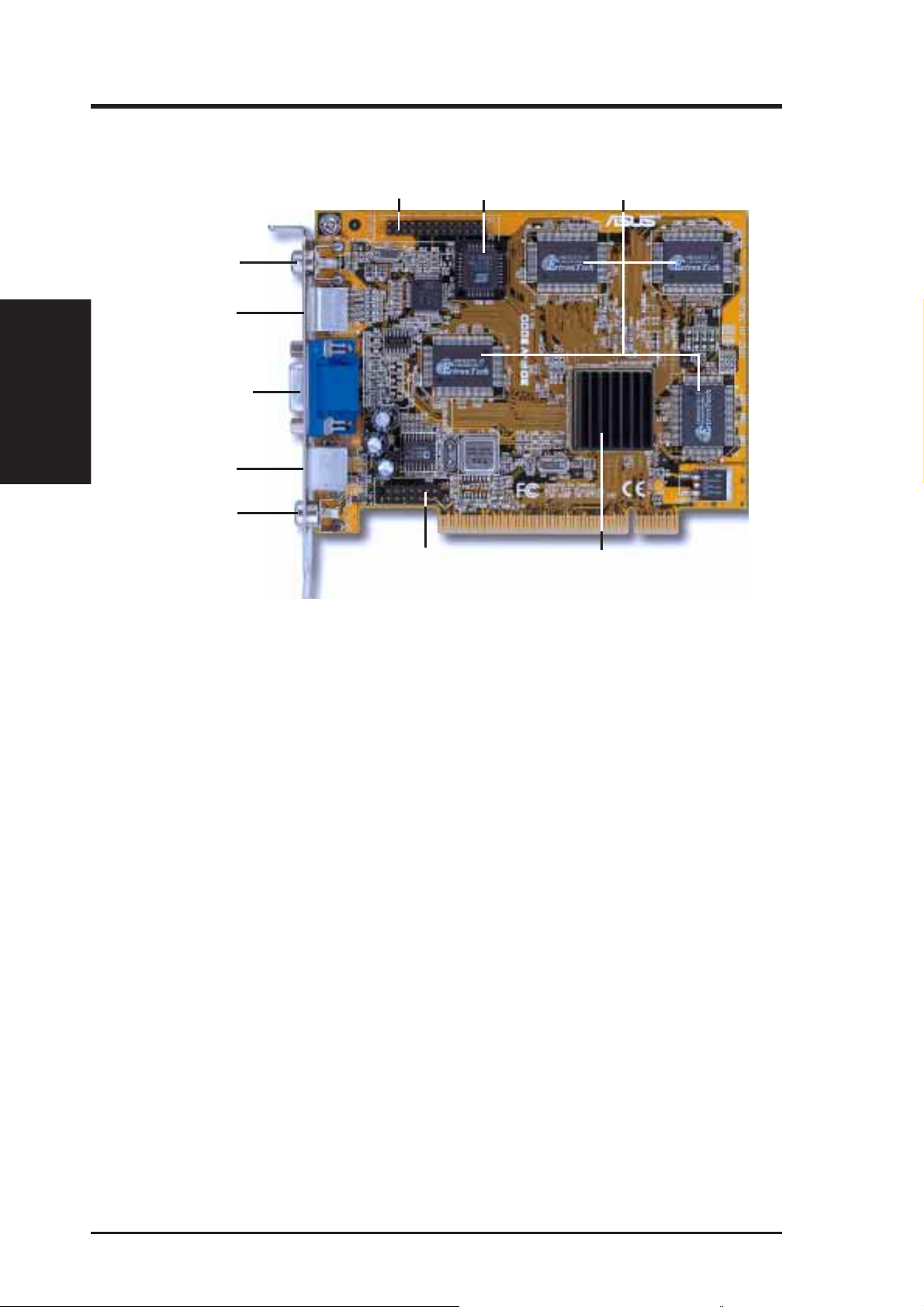
ASUS 3DP-V3000 Layout
CCD / camcorder input
(RCA) (optional)
Tuner/TV Box/SVHS In
II. Installation
(7pin) (optional)
Layout
VGA Monitor Output
(15pin) (standard)
SVHS / TV output
(4pin) (optional)
composite / TV output
(RCA) (optional)
NOTE: The input and output connectors are optional. If either the input and output
connectors are not available, the respective Video Utility will also not be available.
VIP Connector A
VIP Connector B
VGA BIOS
4MB SGRAM Memory
SGS-Thomson
Riva 128™ 3D Chipset
ASUS 3DP-V3000 User’s Manual8
Page 9
II. Hardware Installation
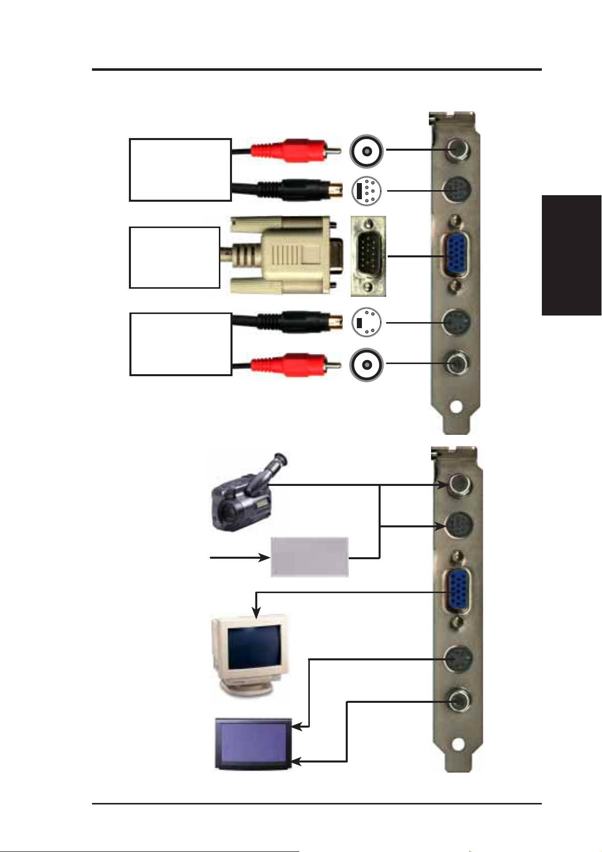
ASUS 3DP-V3000 Connection Examples
Composite
• Camcorder
• Video Cassette Player
• Laser Disc Player
• Other Video Devices
With ASUS Tuner Box:
• TV / FM Tuner
RCA Plug
S-Video or Tuner Box Plug
(RCA) Input
Video
Input
• Computer Monitor
• Video Projector
• Other VGA
Compatible devices
• Camcorder
• Video Cassette Recorder
• Television
• Other Video Displaying
or Recording Devices
15-Pin VGA Plug
S-Video Plug
RCA Plug
VGA
Output
S-Video
Output
Composite
(RCA) Output
NOTES:
• ASUS Video cards come in either NTSC or PAL standards.
• You may not convert NTSC to PAL or vice versa.
• You must use the same standard for all devices.
Connections
II. Installation
CATV
ASUS TV/FM
Tuner Box
9ASUS 3DP-V3000 User’s Manual
Page 10

II. Installation
Procedures
Installation Procedures
New Systems
II. Hardware Installation
WARNING! Computer boards and components contain very delicate Integrated
Circuit (IC) chips. To protect the computer board and other components against
damage from static electricity, you must follow some precautions.
1. Make sure that you unplug your power supply when adding or removing
expansion cards or other system components. Failure to do so may cause
severe damage to both your motherboard and expansion cards.
2. Keep all components such as the host adapter in its antistatic bag until you
are ready to install it.
3. Use a grounded wrist strap before handling computer components. If you do
not have one, touch both of your hands to a safely grounded object or to a
metal object, such as the power supply case. Hold components by the edges
and try not to touch the IC chips, leads, or circuitry.
4. Place components on a grounded antistatic pad or on the bag that came with the
component whenever the components are separated from the system.
1. Unplug all electrical cords on your computer.
2. Remove the system unit cover.
3. Locate the PCI expansion slot. Make sure this slot is unobstructed.
4. Remove the corresponding expansion slot cover from the computer chassis.
5. Ground yourself to an antistatic mat or other grounded source (see WARNING!).
6. Pick up the board (still in its sleeve) by grasping the edge bracket with one hand
and then remove the plastic sleeve.
7. Position the card directly over the PCI slot and insert one end of the board in the
slot first. Firmly but gently press the bus connector on the bottom of the card
down into the slot. Be sure the metal contacts on the bottom of the host adapter
are securely seated in the slot.
8. Anchor the board’s mounting bracket to the computer chassis using the screw
from the slot cover that you set aside previously.
9. Replace the cover on the system unit.
10. Connect your analog monitor’s 15-pin VGA connector to the card and fasten the
retaining screws (if any).
11. Connect other cables and devices if available -You are now ready to install the
software drivers and utilities.
Systems with Existing VGA Card
1. Install the ASUS 3DP-V3000 display drivers with your current VGA card.
2. Shut down your computer and unplug all electrical cords.
3. Replace the existing VGA card with the ASUS 3DP-V3000 graphics card.
4. Restart your computer — the ASUS 3DP-V3000 graphics card should be automatically detected and the display drivers automatically updated.
ASUS 3DP-V3000 User’s Manual10
Page 11

III. Windows 95
Device Connection Notes:
Monitor Out and Video Out (optional)
NOTE: There is a limitation in the signal output. Only one device can be used as an
output device at one time. Choose one output device and disconnect the other. To
use another output device, power off your system, disconnect the current output
device and connect the other output device, then power on your system.
Video In (optional)
Connect your input device(s) and then run the program “ASUS LIVE3000” under
Windows 95 in order to see the external input device(s). See Section III for instructions on installation.
Requirements
III. Windows 95
11ASUS 3DP-V3000 User’s Manual
Page 12

1. Installation for an Installed ASUS 3DP-V3000
“New hardware found” refers to the prompt for drivers when installing W indows 95
with the ASUS 3DP-V3000 VGA card already installed. This Manual assumes that
your CD-ROM disc drive is drive D: and that Windows 95 is in C:\windows . Replace either with the actual location, if necessary.
1.1 Windows 95
When installing Windows 95, a New
Hardware Found window will appear:
Select Do not install a driver and follow
the steps on the next page.
III. Windows 95
Display Driver
III. Windows 95
1.2 Win95 OSR 2.0/2.1
When installing Windows 95 OSR 2.0/2.1,
the Update Device Driver Wizard window
will appear:
This wizard will complete the installation
of the Standard PCI Graphics Adapter
(VGA). Click Cancel.
ASUS 3DP-V3000 User’s Manual12
Page 13

III. Windows 95
Insert the ASUS 3DP-V3000 installation CD with
your current VGA card. The ASUS Windows 95
Install Shell will appear. If it does not appear,
run D:\setup.exe. You will be presented with a
list of install options.
Click Install 3DP-V3000 Display Driver and
follow the installation steps.
The Setup program window appears.
Click
Next > to install 3DP-V3000 display driv-
ers on your computer.
The Features window will be displayed.
Next > to continue with the Setup program.
Click
The Check Setup Information window will appear .
Click
The Installing Microsoft Dir ectX 5 dialog box
will automatically appear because the 3DPV3000 display driver requires DirectX 5 to have
access to the advanced 3D features.
Next > to begin the file transfer.
Display Driver
III. Windows 95
This box indicates that the Setup program is
searching for the updated DirectX Runtime Components and updating as necessary.
13ASUS 3DP-V3000 User’s Manual
Page 14

2. Replacing an Existing VGA Card
If wish to replace an existing VGA card with the
ASUS 3DP-V3000 graphics card, the current
display drivers must be replaced first. T o replace,
insert the ASUS 3DP-V3000 installation CD. The
ASUS Windows 95 Install Shell will appear. If
it does not appear, run D:\setup.exe. You will be
presented with a list of install options.
Click Install 3DP-V3000 Display Driver and
the Setup program window will appear. Click
Next > to install the 3DP-V3000 display drivers
on your computer.
III. Windows 95
Existing Card
III. Windows 95
The Features window will be displayed. Click
Next > to continue with the Setup program.
The Installing Microsoft Dir ectX 5 dialog box
will automatically appear because the 3DPV3000 display driver requries DirectX 5 to have
access to the advanced 3D features. Click
> to begin the file transfer.
Next
This box indicates that the Setup program is
searching for the updated DirectX Runtime Components and updating as necessary.
After all drivers are installed, power off your system and replace your VGA card with the ASUS
3DP-V3000. Restart your computer and the drivers should be installed automatically.
ASUS 3DP-V3000 User’s Manual14
Page 15

III. Windows 95
3. Video Driver Uninstallation
If you want to install other graphics cards or if you no longer need the 3DP-V3000 display
drivers, you can use one of the following procedures to completely uninstall the drivers
from Windows 95 to save disk space.
3.1 Using the Autorun Screen
Insert the ASUS 3DP-V3000 installation CD.
Select Remove 3DP-V3000 Display Driver
in the ASUS Windows 95 Install Shell and
follow the uninstallation steps.
3.2 Using the Windows 95 Control Panel
Click Start, and then point to Settings.
Click Control Panel.
Double-click the Add/Remove Programs icon.
Click the Install/Uninstall tab.
Select ASUS 3DP-V3000 V1.02 (driver ver-
sion) from the list.
Click Add/
During uninstallation, a “Remove Shared
File?” dialog box will display asking you to
remove some shared files. Click the Yes or
Yes T o All button to remove the shared files
that are no longer used.
Remove.
Uninstall Drivers
III. Windows 95
15ASUS 3DP-V3000 User’s Manual
Page 16

III. Windows 95
4. DirectX5 Installation
Microsoft DirectX5 allows 3D hardware acceleration support in Windows 95. For
Software MPEG support in W indows 95, you must first install the Microsoft DirectX
5 libraries, then you may install the MPEG Video Player.
Reinsert your CD or double click on your
CD drive icon in My Computer to bring up
the autorun screen or run Setup.exe in the
root directory of the CD.
Click Install Microsoft DirectX5
III. Windows 95
DirectX5
DirectX5 Setup Screen Appears
Check Direct 3D Hardware Acceleration
Enabled and then click the Reinstall
DirectX button.
If your system already has DirectX5 installed, the screen will show “Certified”
next to each component. You may click either the “Ok” or “Cancel” button to cancel the installation.
After reinstalling DirectX5, you will be
prompted to restart your machine. Click
the “Ok” button.
ASUS 3DP-V3000 User’s Manual16
Page 17

III. Windows 95
5. Video Utility (optional)
ASUS LIVE3000
ASUS LIVE3000 must be installed in order to use the video-in function on the 3DPV3000.
After installation, you may run the program
through the “Start” button-ProgramsASUS LIVE3000-LIVE3000 or remove
the program using the unInstallSHIELD.
When first using ASUS LIVE3000, you
must choose Options-Video Source from
the pull-down menu.
Video Source allows you to select:
• Video Connector type:
• Select your local Video Standard
• Adjust Color if necessary.
Video Utility
III. Windows 95
17ASUS 3DP-V3000 User’s Manual
Page 18

III. Windows 95
6. PowerPlayer
PowerPlayer is a video player that allows you to view VCD (*.DAT) or MPEG
(*.MPG) CD titles.
Reinsert your CD or double click on your
CD drive icon in My Computer to bring
up the autorun screen or run Setup.exe in
the root directory of the CD.
III. Windows 95
PowerPlayer
Follow the self-explanatory instructions to
complete the installation.
Moving your cursor over the buttons will
give the command name. If you need help,
click the “?” button.
LIMITATIONS:
• Do not run PowerPlayer with full screen under 1280x1024 16bit high color or
1600x1200 16bit high color resolution modes, it will not function properly.
• Do not overlap other windows over PowerPlayer, it will not function properly.
ASUS 3DP-V3000 User’s Manual18
Page 19

IV. Microsoft Windows NT
Windows NT 4.0
Installation Procedures
1. Start W indows NT , switch display properties to VGA mode (16 colors, 640 x 480
pixels), then restart your computer to make the change.
2. After your computer restarts, right-click the desktop and click Properties.
3. Click the Settings tab.
4. Select Change Display Type.
5. Select Adapter Type and click Change.
6. Click Have Disk.
7. Insert the ASUS 3DP-V3000 Installation CD.
8. Type D:\NT40 (assuming your CD-ROM disc drive is in drive D) or click Browse
to select the path of the display driver for Windows NT. Click OK.
9. You will see a list of ASUS 3DP-V3000 drivers. Select ASUS 3DP-V3000 and
then click OK.
10. Windows NT will once again prompt for confirmation. All appropriate files are
then copied to the hard disk. When all files are copied, go back to the Display
Properties box by clicking Close. Click Apply .
11. The System Settings Change dialog box is displayed. Click
12. Windows NT will restart with the default settings. The Display applet will appear to allow for mode selection.
Yes to restart Windows.
Display Driver
IV. Windows NT
ASUS 3DP-V3000 User’s Manual 19
Page 20

IV. Microsoft Windows NT
Windows NT 3.51
After installing your graphics card, WinNT3.51 will default to the standard VGA
mode (640x480, 16 colors). The procedure below describes how you install ASUS
3DP-V3000 series display driver for WinNT3.51.
Installation Procedures
1. Start W indows NT , switch display properties to VGA mode (16 colors, 640 x 480
pixels), then restart your computer to make the change.
2. After your computer restarts, right-click the desktop and click Properties.
3. Click the Settings tab.
4. Select Change Display Type.
5. Select Adapter Type and click Change.
6. Click Have Disk.
7. Insert the ASUS 3DP-V3000 Installation CD.
8. Type D:\NT351 (assuming your CD-ROM disc drive is in drive D) or click
IV. Windows NT
Display Driver
9. You will see a list of ASUS 3DP-V3000 drivers. Select ASUS 3DP-V3000 and
10. Windows NT will once again prompt for confirmation. All appropriate files are
11. The System Settings Change dialog box is displayed. Click
12. Windows NT will restart with the default settings. The Display applet will ap-
Browse to select the path of the display driver for Windows NT. Click OK.
then click OK.
then copied to the hard disk. When all files are copied, go back to the Display
Properties box by clicking Close. Click Apply .
Yes to restart Windows.
pear to allow for mode selection.
20 ASUS 3DP-V3000 User’s Manual
Page 21

V. Windows 3.x
This Manual assumes that you have already installed the ASUS 3DP-V3000 graphics & video card and your CD-ROM disc drive is drive D: and that the W indows 3.x
directory is in C :\windows. Replace these with the actual location, if necessary . The
ASUS 3DP-V3000 V ideo drivers for W indows 3.x can be installed under DOS mode
or Windows 3.x.
1.1. Installation Procedures in DOS
1. Start your computer and enter DOS mode.
2. Type D: and change to the \WIN31 directory.
3. Type install and the install screen will appear.
4. Type c:\windows or the path to your Windows 3.x directory.
5. The installation program will install the appropriate language support into Windows.
6. When completed, keep your ASUS driver CD in your CD-ROM disc drive and
launch Windows 3.x.
7. The ASUS Video installation screen will appear. You may select other items to
install.
ASUS 3DP-V3000 User’s Manual 21
V. Windows 3.x
Installation in DOS
Page 22

V. Windows 3.x
1.2. Installation Procedures in Windows 3.x
1. Start your computer in DOS mode.
2. Change to your Windows 3.x directory.
3. Type SETUP. The System Information screen will appear.
4. Go to the Display section and then select VGA. Switch to the standard VGA
mode (16 colors, 640 x 480 pixels), then start Windows by typing WIN.
5. Insert the ASUS 3DP-V3000 installation CD and run D:\setup.exe. A list of
install options will appear.
Installation in Win3.x
V. Windows 3.x
6. Click Install Windows 3.x Display Driver and follow the installation steps.
22 ASUS 3DP-V3000 User’s Manual
Page 23

V. Windows 3.x
1.3. Installation of Video for Windows
For Software MPEG support in W indows 3.x, you must first install Microsoft Video
for Windows, then you may install your own MPEG Video Player.
NOTE: ASUS does not provide an MPEG Video Player.
1. Start W indows 3.x.
2. Insert the ASUS 3DP-V3000 Installation CD.
3. Run D:\setup.exe. A list of install options will appear.
4. Click Install Win32s Runtime Library.
NOTE: Part of the driver’s code is written with 32bit API, which will need the
Win32s Runtime Library to be executable. It is recommended that you install
Win32s Runtime Library once you have installed the Windows 3.x driver.
5. Click Install Video for W indows if you have not installed Video for Windows.
NOTE: Y ou must install Win32S Runtime Library first. Otherwise, the DCI driver
of Video for Windows will not be enabled.
V. Windows 3.x
Video for Windows
ASUS 3DP-V3000 User’s Manual 23
Page 24

(This page was intentionally left blank)
○○○○○○○○○○○○○○○○○○○○○○○○○○○○○○○○○○○○○
○○○○○○○○○○○○○○○○○○○○○○○○○○○○○○○○○○○○○
○○○○○○○○○○○○○○○○○○○○○○○○○○○○○○○○○○○○○
○○○○○○○○○○○○○○○○○○○○○○○○○○○○○○○○○○○○○
○○○○○○○○○○○○○○○○○○○○○○○○○○○○○○○○○○○○○
○○○○○○○○○○○○○○○○○○○○○○○○○○○○○○○○○○○○○
○○○○○○○○○○○○○○○○○○○○○○○○○○○○○○○○○○○○○
○○○○○○○○○○○○○○○○○○○○○○○○○○○○○○○○○○○○○
○○○○○○○○○○○○○○○○○○○○○○○○○○○○○○○○○○○○○
○○○○○○○○○○○○○○○○○○○○○○○○○○○○○○○○○○○○○
○○○○○○○○○○○○○○○○○○○○○○○○○○○○○○○○○○○○○
○○○○○○○○○○○○○○○○○○○○○○○○○○○○○○○○○○○○○
○○○○○○○○○○○○○○○○○○○○○○○○○○○○○○○○○○○○○
○○○○○○○○○○○○○○○○○○○○○○○○○○○○○○○○○○○○○
○○○○○○○○○○○○○○○○○○○○○○○○○○○○○○○○○○○○○
○○○○○○○○○○○○○○○○○○○○○○○○○○○○○○○○○○○○○
○○○○○○○○○○○○○○○○○○○○○○○○○○○○○○○○○○○○○
○○○○○○○○○○○○○○○○○○○○○○○○○○○○○○○○○○○○○
○○○○○○○○○○○○○○○○○○○○○○○○○○○○○○○○○○○○○
○○○○○○○○○○○○○○○○○○○○○○○○○○○○○○○○○○○○○
○○○○○○○○○○○○○○○○○○○○○○○○○○○○○○○○○○○○○
○○○○○○○○○○○○○○○○○○○○○○○○○○○○○○○○○○○○○
○○○○○○○○○○○○○○○○○○○○○○○○○○○○○○○○○○○○○
○○○○○○○○○○○○○○○○○○○○○○○○○○○○○○○○○○○○○
○○○○○○○○○○○○○○○○○○○○○○○○○○○○○○○○○○○○○
○○○○○○○○○○○○○○○○○○○○○○○○○○○○○○○○○○○○○
○○○○○○○○○○○○○○○○○○○○○○○○○○○○○○○○○○○○○
○○○○○○○○○○○○○○○○○○○○○○○○○○○○○○○○○○○○○
○○○○○○○○○○○○○○○○○○○○○○○○○○○○○○○○○○○○○
○○○○○○○○○○○○○○○○○○○○○○○○○○○○○○○○○○○○○
○○○○○○○○○○○○○○○○○○○○○○○○○○○○○○○○○○○○○
○○○○○○○○○○○○○○○○○○○○○○○○○○○○○○○○○○○○○
○○○○○○○○○○○○○○○○○○○○○○○○○○○○○○○○○○○○○
○○○○○○○○○○○○○○○○○○○○○○○○○○○○○○○○○○○○○
○○○○○○○○○○○○○○○○○○○○○○○○○○○○○○○○○○○○○
○○○○○○○○○○○○○○○○○○○○○○○○○○○○○○○○○○○○○
○○○○○○○○○○○○○○○○○○○○○○○○○○○○○○○○○○○○○
○○○○○○○○○○○○○○○○○○○○○○○○○○○○○○○○○○○○○
○○○○○○○○○○○○○○○○○○○○○○○○○○○○○○○○○○○○○
○○○○○○○○○○○○○○○○○○○○○○○○○○○○○○○○○○○○○
○○○○○○○○○○○○○○○○○○○○○○○○○○○○○○○○○○○○○
24 ASUS 3DP-V3000 User’s Manual
Page 25

VI. Display Information
Resolution Table
4MB Video Memory
Resolution Vertical Horizontal
Frequency Frequency
640 x 480 60Hz 31.4KHz üü ü
72Hz 36.1KHz üü ü
75Hz 37.6KHz üü ü
85Hz 43.0KHz üü ü
100Hz 50.9KHz üü ü
120Hz 61.8KHz üü ü
800 x 600 60Hz 37.9KHz üü ü
72Hz 45.1KHz üü ü
75Hz 47.1KHz üü ü
85Hz 53.5KHz üü ü
100Hz 63.6KHz üü ü
120Hz 77.3KHz üü ü
Color Depth
8bpp = 16bpp = 32bpp =
256 colors 65K colors
Standard High Color True Color
Resolution Table
VI. Display Info
1024 x 768 60Hz 48.4KHz üü ü
72Hz 57.6KHz üü ü
75Hz 60.2KHz üü ü
85Hz 68.7KHz üü ü
100Hz 81.9KHz üü ü
120Hz 98.8KHz üü ü
1152 x 864 60Hz 53.6KHz üü ü
72Hz 64.9KHz üü ü
75Hz 67.7KHz üü ü
85Hz 77.2KHz üü ü
100Hz 91.4KHz üü ü
120Hz 110.8KHz üü ü
1280 x 1024 60Hz 64.0KHz üü
72Hz 77.0KHz üü
75Hz 80.4KHz üü
85Hz 91.2KHz üü
100Hz 108.5KHz üü
1600 x 1200 60Hz 74.9KHz üü
72Hz 89.9KHz üü
75Hz 93.8KHz üü
85Hz 107.1KHz üü
ASUS 3DP-V3000 User’s Manual 25
Page 26

VIP Connectors
VIP uses two dual row 0.1” center connectors — Connector A and Connector B.
Connector A is a 26-pin connector, which is the same as the standard Feature Connector. Connector B is a 14-pin connector consisting of the power pins, ground,
VRST#, and I2S. On the master side, Connector A is male, and Connector B is
VII. Hardware Info
VIP Connectors
female. This applies to either the graphics adapter card or the motherboard. Slave
modules will have the opposite mating connectors. Connector B on the slave side
must be shrouded to prevent the danger of wrong insertion. Connector A can be
configured as a standard Feature Connector, VIP, or Connector A (video) of VMI
1.4. On power up, the graphics chip (master) is configured in the standard feature
connector mode. All VIP slaves must be disabled and tri-stated on power up.
VIP Module Mechanical Specification
VII. Hardware Information
26
25
Connector A-PT - 26 Pin Right Angle
Male (for Ribbon Cable Pass-thru)
VIP Module
(Component Side)
Shrouded Connector
14
13
Connector B
14 Pin Male
2
1
2
1
26 ASUS 3DP-V3000 User’s Manual
Page 27

VII. Hardware Information
VIP CONNECTOR A
(26 Pin Dual Row Header, 0.100 in. centers)
Standard Feature VIP Standard Feature VIP
Connector Mode Connector Mode
Pin # Signal Name Signal Name Pin # Signal Name Signal Name
1 Ground Ground 2 P0 VID [0]
3 Ground Ground 4 P1 VID [1]
5 Ground Ground 6 P2 VID [2]
7 EVIDEO # HAD [1] 8 P3 VID [3]
9 ESYNC # HAD [0] 10 P4 VID [4]
11 EDCLK # HCTL 12 P5 VID [5]
13 N/C SCL 14 P6 VID [6]
15 Ground Ground 16 P7 VID [7]
17 Ground Ground 18 DCLK PIXCLK
19 Ground Ground 20 BLANK # VIPCLK
21 Ground Ground 22 HSYNC N/C
23 N/C VIRQ # 24 VSYNC N/C
25 N/C SDA 26 Ground Ground
VIP Connectors
VII. Hardware Info
VIP CONNECTOR B
(14 Pin Dual Row Header, 0.100 in. centers)
Standard Feature VIP Standard Feature VIP
Connector Mode Connector Mode
Pin # Signal Name Signal Name Pin # Signal Name Signal Name
1 - +3.3V 2 - +3.3V
3 - +3.3V 4 - +3.3V
5 - Ground 6 - Ground
7 - +5V 8 - +5V
9 - +5V 10 - VRST #
11 - SCLK 12 - Ground
13 - LRCLK 14 - PCMDA TA
ASUS 3DP-V3000 User’s Manual 27
Page 28

VIII. Troubleshooting
Description
After installing the driver,
Windows 95 doesn't
prompt me to restart and
the driver still doesn't
work after I restart my
computer.
VIII. Troubleshooting
Descriptions/Actions
Recommended Action
You may have installed similar drivers before. Try the
following steps to install:
1. Right-click My Computer on the desktop.
2. Select Properties. The System Properties dialog
box appears.
3. Click the Device Manager tab. Be sure that View
devices by type is selected.
4. Double-click Display adapters. If Display adapt-
ers does not appear, jump to step 8 and continue.
5. The name of your card will be listed in the box.
Double-click it.
6. The properties box of your card appears. Click the
Driver tab.
7. Click Change Driver ... and follow the installation steps.
8. Click Other devices. Your card should be listed.
9. Click the name of your card to bring up the properties box of your card. Select the Driver tab.
10. Click Change Driver ... and follow the installation steps.
After installation and restarting, Windows 95 informs me that the display
setting is still incorrect.
My monitor is not capable
of high resolution or refresh rate.
There may be a conflict between a previous and the
current display drivers. This is caused by the incomplete removal of the previous display driver. Try the
following steps to remove it:
1. Right-click My Computer on the desktop.
2. Select Properties. The System Properties dialog
box appears.
3. Click the Device Manager tab. Be sure that View
devices by type is selected.
4. Double-click Display adapters.
5. You will find two (or more) conflicting adapters.
6. Disable all previous adapters by selecting them and
clicking Remove.
7. Close Device Manager and restart Windows 95.
8. Y our display driver should work correctly this time.
It depends on the display characteristics of your monitor . Consult your monitor documentation for the proper
configuration.
28 ASUS 3DP-V3000 User’s Manual
 Loading...