

Page 1
Astronics CSC
THIS DOCUMENT HAS BEEN ELECTRONICALLY SIGNED IN ASTRONICS CSC’S PLM
SYSTEM. ALL ELECTRONIC SIGNATURES ARE ON FILE IN THE PLM SYSTEM AND ARE
FULLY AUDITABLE.
Document Control RELEASED
E71-314
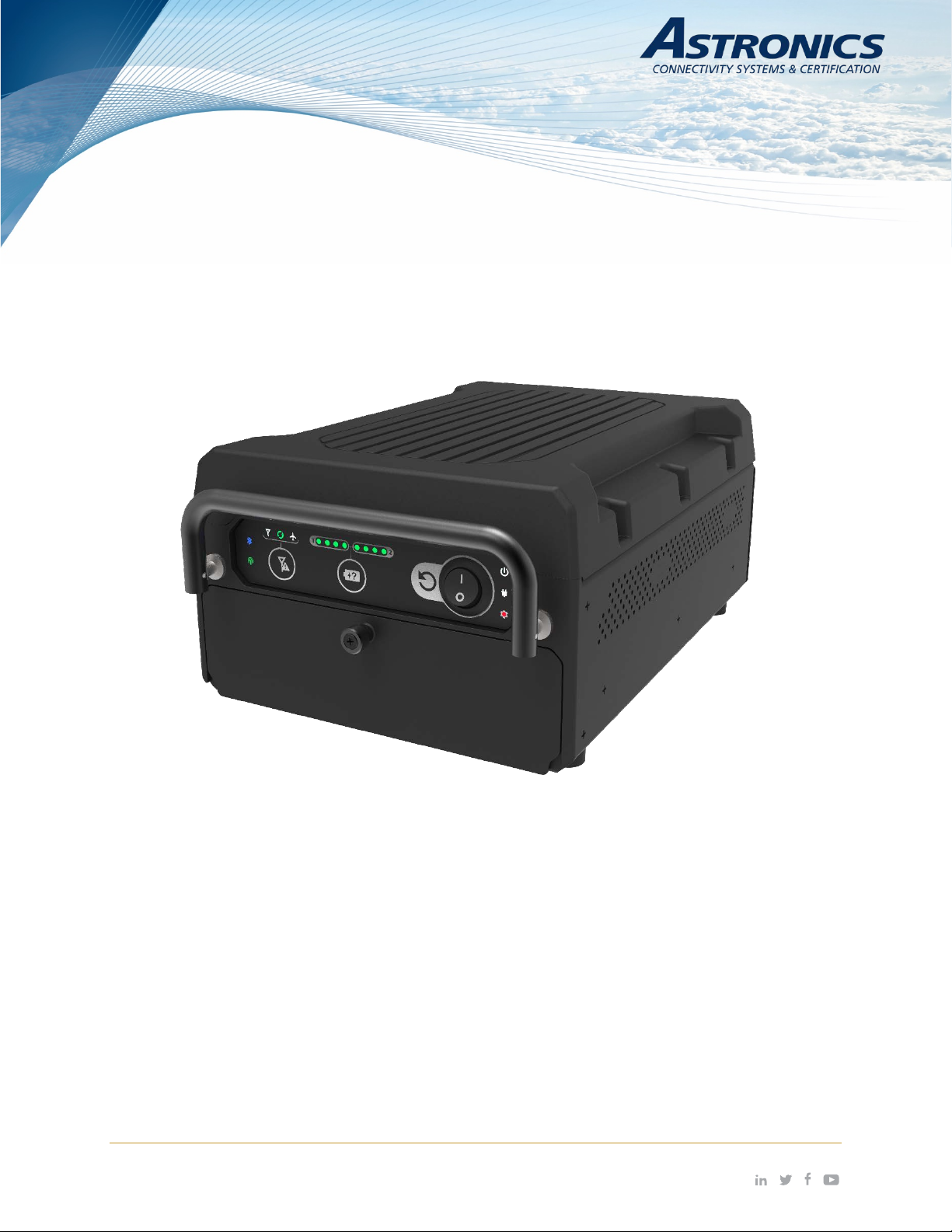
Sierra™
User’s Manual
THIS DOCUMENT IS THE SOLE PROPERTY OF ASTRONICS CONNECTIVITY SYSTEMS & CERTIFICATION (“ASTRONICS CSC”) AND SHALL
NOT BE REPRODUCED, COPIED OR ISSUED AS THE BASIS OF MAINTENANCE OR SALE OF APPARATUS WIHTOUT PERMISSION OF
ASTRONICS CSC.
804 S. Northpoint Blvd. | Waukegan, IL 60085 astronics.com
+1.847.244.4500
Inflight Entertainment and Connectivity Systems
Page 2
Copyright
© Copyright 2019 Astronics CSC. Astronics CSC trademarks include , Sierra™, Cabin Ace™,
Cabin Pinnacle™, Cabin Vista™, Edge ™, All rights reserved. All other trademarks are the property of their
respective owners.
Open Source Code
This product includes code licensed under GNU General Public License, and/or certain other open source
licenses.
FCC COMPLIANCE STATEMENT
CAUTION: Changes or modifications not expressly approved could void your authority to use this
equipment.
This device complies with Part 15 of the FCC Rules. Operati on to the following two conditions: (1) This
device m ay not cause harmf ul interference, and (2) t his device must accept any interference recei ved,
including interference that may cause undesired operation.
INDUSTRY CANADA COMPLIANCE STATEMENT
This device com plies with Industr y Canada licence-ex empt RSS stan dard(s). Operation is subject to th e
following two conditions : (1) this device m ay not cause interf erence, and (2) this device m ust accept any
interference, including interference that may cause undesired operation of the device.
Le présent appareil est conforme aux CNR d'Industrie Canada applicables aux appareils radio exempts de
licence. L'exploitatio n est autorisée aux deux conditions suivantes : (1) l'a ppareil ne doit pas pr oduire de
brouillage, et (2) l'utilisateur de l'appareil doit accepter tout brouillage radioélectrique subi, m ême si le
brouillage est susceptible d'en compromettre le fonctionnement.
EUROPEAN UNION COMPLIANCE STATEMENT
Hereby, Astronics CSC, declares that this Sierra™ Portable Inflight Entertainment (IFE) System is in
compliance with the essential requirements and other relevant provisions of Directive 2014/53/EU. The full
text of the EU declaration of conformity is available at the following internet address:
https://www.astronics.com/subsidiary?subsidiaryItem=astronics%20connectivity%20systems%20and%20
certification
Page | 2 Revision Date January 28, 2020 || Document Number UM-E71-314 || Rev A
astronics.com
Page 3

1 TABLE OF CONTENTS
1 User Information .................................................................................................................................... 6
1.1 Support Documentation ................................................................................................................ 6
1.2 Industry Standards ........................................................................................................................ 7
1.3 Warranty ........................................................................................................................................ 7
1.4 Exclusion of Liability Notice ........................................................................................................... 7
2 Important Safety Instructions ................................................................................................................ 8
2.1 Safety and Precautions ................................................................................................................. 8
2.2 Regulatory ..................................................................................................................................... 8
2.3 Battery Safety .............................................................................................................................. 12
3 Introduction .......................................................................................................................................... 14
3.1 Product Description ..................................................................................................................... 14
3.2 Hardware Architecture ................................................................................................................ 15
3.3 Key Hardware Components ........................................................................................................ 16
3.4 Orderable Part Numbers ............................................................................................................. 18
4 Powering Up ........................................................................................................................................ 19
5 Connecting to Sierra ........................................................................................................................... 20
5.1 Terminal Communication Settings .............................................................................................. 20
5.2 SSH ............................................................................................................................................. 21
5.3 SSID ............................................................................................................................................ 21
5.4 WAP Configuration ...................................................................................................................... 22
6 Connecting using Aruba’s Web-based GUI ........................................................................................ 23
7 WLAN Setup........................................................................................................................................ 30
8 User Interface ...................................................................................................................................... 36
8.1 Switch and Display Panel ............................................................................................................ 36
8.2 Battery Status Indicator ............................................................................................................... 38
8.3 Cellular Mode Button ................................................................................................................... 38
8.4 Battery Door ................................................................................................................................ 38
9 Performance Data ............................................................................................................................... 43
9.1 Aruba Wi-Fi Characteristics ........................................................................................................ 43
9.2 Country Codes ............................................................................................................................ 45
10 Technical Data ................................................................................................................................ 47
10.1 Electrical and Env ironmental Specifications ............................................................................... 47
10.2 Mechanical Desi gn and Di mensions ........................................................................................... 48
10.3 Workmanship .............................................................................................................................. 53
10.4 Safety .......................................................................................................................................... 53
11 Reliability and Maintainability .......................................................................................................... 54
11.1 Reliability ..................................................................................................................................... 54
11.2 Maintainability.............................................................................................................................. 54
11.3 Mean Time to Repair (MTTR) ..................................................................................................... 54
11.4 Failure Detection and Fault Isolation .......................................................................................... 54
11.5 Production Testing ...................................................................................................................... 54
12 Support and Service ........................................................................................................................ 55
Page | 3 Revision Date January 28, 2020 || Document Number UM-E71-314 || Rev A
astronics.com
Page 4

12.1 Technical Support ....................................................................................................................... 55
12.2 Returning Defective Equipment .................................................................................................. 55
Table of Tables
Table 1-1: Astronics CSC Suppor t Doc umentation ...................................................................................... 6
Table 1-2: Aruba Support Documentation .................................................................................................... 6
Table 1-3: Industry Standar ds ....................................................................................................................... 7
Table 3-1: Sierra Kit Specific Drawing Information ..................................................................................... 15
Table 3-2: Sierra Orderable Part Numbers ................................................................................................. 18
Table 5-1: Com Port Settings ...................................................................................................................... 20
Table 8-1: Switch and Displa y Panel Nom enc lature and Function ............................................................. 36
Table 9-1: Radio Characteristics ................................................................................................................. 43
Table 9-2: RF Performance Table .............................................................................................................. 44
Table 9-3: Country Codes ........................................................................................................................... 45
Table 10-1: Engineering Test Matrix ........................................................................................................... 47
Page | 4 Revision Date January 28, 2020 || Document Number UM-E71-314 || Rev A
astronics.com
Page 5

Table of Figures
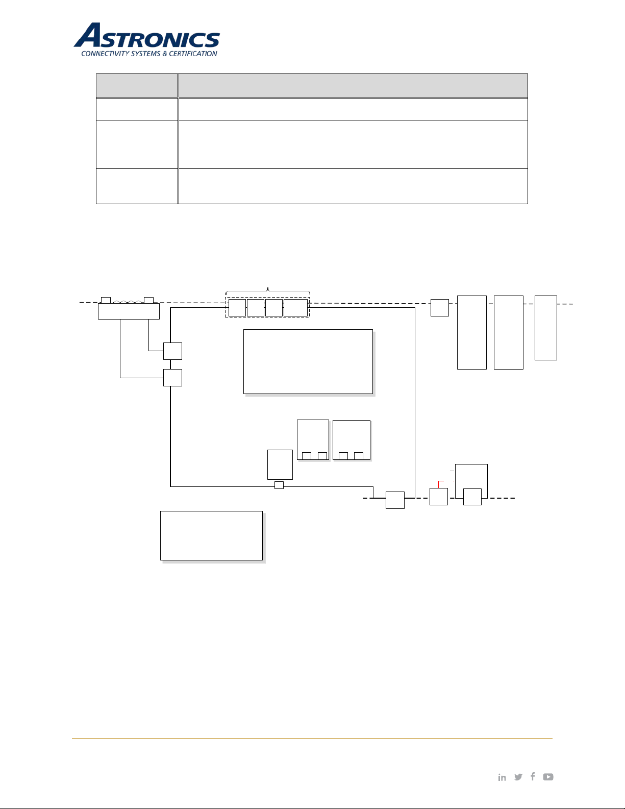
Figure 3-1: Sierra System Block Diagram ................................................................................................... 17
Figure 3-2: Sierra™ Equipment .................................................................................................................. 18
Figure 4-1: Power Source ........................................................................................................................... 19
Figure 4-2: Power On/Off Switch and Power Indicator ............................................................................... 19
Figure 5-1: USB-C connection .................................................................................................................... 20
Figure 5-2: Ethernet Port ............................................................................................................................. 21
Figure 6-1: Aruba Instant GUI Login Prompt .............................................................................................. 23
Figure 6-2: The Six Sections of the Aruba Instant Main GUI Page ............................................................ 24
Figure 6-3: System Username and Password Dialog Box. ......................................................................... 25
Figure 6-4: Additional Network Information ................................................................................................. 26
Figure 6-5: Signal Speed Popup Window ................................................................................................... 26
Figure 6-6: The Wireless network Usage Trends Section .......................................................................... 27
Figure 6-7: Information Band Display for Selected Access Point ............................................................... 27
Figure 6-8: Radio Specific Details ............................................................................................................... 28
Figure 6-9: Clients Section .......................................................................................................................... 28
Figure 6-10: Client Details ........................................................................................................................... 29
Figure 7-1: The Four Stages to Creating an SSID ...................................................................................... 30
Figure 7-2: The WLAN Settings Tab of the New WLAN Dialog Box........................................................... 31
Figure 7-3: The VLAN Tab of the New WLAN Dialog Box .......................................................................... 32
Figure 7-4: Configuring an External RADIUS Server .................................................................................. 33
Figure 7-5: Configuring Firewall Rules ........................................................................................................ 34
Figure 7-6: External Captive Portal Settings ............................................................................................... 35
Figure 8-1: Switch and Display Panel ......................................................................................................... 36
Figure 8-2: Battery State-of-Charge Indicator ............................................................................................. 38
Figure 8-3: Battery Door .............................................................................................................................. 39
Figure 8-4: Hardware Interface behind the battery door ............................................................................. 40
Figure 8-5: Removable SSD Ejection Instructions ...................................................................................... 41
Figure 8-6: Removable SSD Installation Instructions ................................................................................. 42
Figure 10-1: Sierra Top View ...................................................................................................................... 48
Figure 10-2: Sierra I/O Front View .............................................................................................................. 49
Figure 10-3: Sierra Side View ..................................................................................................................... 49
Figure 10-4: Sierra Rear View .................................................................................................................... 50
Figure 10-5: Sierra Bottom View ................................................................................................................ 50
Page | 5 Revision Date January 28, 2020 || Document Number UM-E71-314 || Rev A
astronics.com
Page 6
E71-314-XXX-OL
*
E54-576-XX-OL
*
44-20-45
Component Maintenance Manual (CMM), Sierra
FMEA-E71-314
This User Guide describes the features supported by Aruba
setting up and
configuring the Inst ant net wor k.
Aruba Instant CLI Reference
1 User Information
This User’s Manual describes the features supported by Astronics CSC third generation streaming portable
TM
Inflight Entertainm ent (IFE) system , branded as Sierra
and provides deta iled instructions f or setting up
and configuring the Sierra IFE portable system.
This guide is intended for administrators who configure and use Sierra.
1.1 Support Documentation
In addition to this document, the following table describes Astronics CSC support documentation:
Table 1-1: Astronics CSC Support Documentation
Document Number Description
E71-319-01-OL Outline Drawing, Assembly, Sierra Base Unit
PS-E71-314 Product Specification, Sier ra
ATP-E71-314 Acceptance Test Procedure (ATP), Sierra
*
See Table 3-1 for kit specific –OL drawings.
Outline Drawing, Sierra Kit Assembly, Removable SSD
Outline Drawing, Assembly, Removable SSD
Failure Modes and Effects Analysis (FMEA), Sierra
Sierra ships with Aruba Ins tant firm ware. The f ollowin g table d escribes th e applic able Ar uba suppor t
documentation for this firmware version.
Table 1-2: Aruba Support Documen tat ion
Document Name Description
Aruba Instant User Guide
Instant and provides detailed instructions for
This document desc ribes the Aruba Instant com mand syntax
Guide
and provides information for each Command.
Page | 6 Revision Date January 28, 2020 || Document Number UM-E71-314 || Rev A
astronics.com
Page 7
Cabin Equipment Interfaces, Part 1, Interfaces, Cabin
Management and Entertainment Systems - Peripherals
A set of media access c ontrol ( MAC) and p hys ical la yer ( PHY)
ess local area network
5, and 60 GHz frequency bands.
A set of media access c ontrol ( MAC) and p hys ical la yer ( PHY)
computer communication.
Environmental Conditions and Test Procedures for Airborne
178B Software Considerations in
Airborne Systems and Equipment
Spectrum and Transmit Power Management Extensions (TPC)
regulatory maximum to reduce interference to satellites.
1.2 Industry Standards
Industry Standard Description
ARINC 628
Table 1-3: Industry Standards
IEE 802.11
IEE 802.3
RTCA/DO-160G
802.11h
specifications for implementing wirel
(WLAN) computer communication in the 900 MHz and 2.4, 3.6,
specifications for implementing wired local area n et wor k (LAN)
Equipment RTCA/DO-
is supported to ensure that the average po wer is less than the
1.3 Warranty
The Sierra is warranted against defects in materials and workmanship for the warranty period from the
date of shipment. The warranty does not apply to defects resulting from improper or inadequate
maintenance of handling b y the buyer, una uthori zed m odification or mis use, operation o utside of the
product’s environm ental specif ication of im proper inst allation or m aintenance. As tronics CSC will not
be responsible for an y defects or damages to other pr oducts not s upplied by Astronics CSC that are
caused by a faulty Astronics CSC product.
1.4 Exclusion of Liability Notice
Should the user disregard the instructions (specifically the safety instructions) in this manual and
possibly on the device, Astronics CSC shall be exempt from legal liability for accidents.
In the event of damage to the device, which is caused by a failure to observe the instructions
(specifically the safety instructions) in this manual and possibly on the device, Astronics CSC shall not
be required to honor the warranty, including during the warranty period, and shall be exempt from legal
liability of accidents.
Page | 7 Revision Date January 28, 2020 || Document Number UM-E71-314 || Rev A
astronics.com
Page 8

2 Important Safety Instructions
2.1 Safety and Precautions
The following gener al instr uctions should al ways b e followe d in order to ass ure the proper op eration
of Sierra, the safety of operators and the preservation of warranty coverage.
1. The Sierra IFE System has been desi gne d to operate in the pressurized passenger cabin on
the aircraft. Never operate the Sierra IFE System in unpressurized areas of the aircraft Avoid
removing any identification plates, serial numbers or warning labels unless specifically
authorized by the manufac turer.
2. To maximize battery life, the Si erra IFE System has been designed to o perate with passi ve
cooling in temperatures from 0°C to +50°C. To prevent overheating, be sure there is adequate
air flow around th e device, and that the heat dissipat ion holes are n ot blocked. A m inimum
airgap of 1” sh ould be main tained during operation. P lease o bser ve all specif ied dim ensions
required for mounting, included in the kit specific Outline Drawing listed in Table 3-1.
3. Sierra has been designed to withstand the mechanical vibrations associated with aircraft
transport, but care should still be taken to provide a stable location and avoid any unnecessary
sliding, shifting, or damage from unsecured cargo.
4. Do not expose Sierra to rain or snow. Care should be taken when transporting to and from the
aircraft.
2.2 Regulatory
Sierra contains the following Intentional Radiators:
Wi-Fi Transceiver
FCCID: 2AL4H-E7131901
IC: 22737-E7131901
Aux Wi-Fi Transceiver
FCCID: PD98265NG
IC: 1000M-8265NG
Cellular Transceiver
FCCID: N7NEM75
IC:2417C-EM75S
Page | 8 Revision Date January 28, 2020 || Document Number UM-E71-314 || Rev A
astronics.com
Page 9

2.2.1 USA – FCC Supplier Declaration of Conformity Product Identification and Responsible Party
Astronics CSC
804 S. Northpoint Blvd.
Waukegan, IL 60085
(847) 244-4500
www.astronics.com
We, Astronics CSC , 804 S. Northpoint Blvd. Waukegan, IL 60085, declare under our sole responsibility
that the product E71-314 Sierra™ complies with Part 15 Subpart B of FCC CFR47 Rules.
This device complies with part 15 of the FCC Rules. Operation is subject to the following two
conditions: (1) This device may not caus e harmful i nterferenc e, and (2) this device m ust accept an y
interference received, including interference that may cause undesired operation.
Any changes or modif ications not expr essly approve d by the part y responsible f or complianc e could
void the user’s authority to operate this equipment.
2.2.1.1 Information to User
Class B Digital Device
NOTE: This equipment has been tested and found to comply with the limits for a Class B digital device,
pursuant to part 15 of the FCC Rules. These limits are des igned to provide reasonable prot ection
against harmful int erference in a residential installat ion. This equipment generates, uses, and can
radiate radio frequency energy and, if not installed and used in accordance with the instructions, may
cause harmful interference to radio communications. However, there is no guarantee that interference
will not occur in a particu lar installat ion. If this equi pm ent does cause harm ful int erf erence to r adio or
television reception, which can be determined by turning the equipment off and on, the user is
encouraged to try to correct the interference by one or more of the following measures:
- Re-orient or relocate the receiving antenna.
- Increase the separation between the equipment and receiver.
- Connect the equipm ent into an outlet on a circ uit different fr om that to which th e receiver is
connected.
Do not operate the cellular transceiver module:
- Where explosive atm ospheres may be pres ent, including refueling po ints, fuel depots, an d
chemical plants.
- Near medical equipment, life support equipment, or any equipment which may be susceptible
to any form of r adio interference. In such areas, the cellular transce iver module MUST BE
POWERED OFF. Otherwise, the cellular module can transmit signals that could interfere with
this equipment.
In an aircraft, the c ellul ar tr ansc eiver m odule MU ST BE POW ERED O FF. O therwis e, the tr ans ceiver
module can transmit signals that could interfere with various onboard systems and may be dangerous
to the operation of the aircraf t or disrupt t he cell ular networ k. Us e of a cellular p hone in an aircraf t is
illegal in some jur isdictions. Failure to observe this in struction may lead to suspension or den ial of
cellular telephone services to the offender, or legal action, or both.
Page | 9 Revision Date January 28, 2020 || Document Number UM-E71-314 || Rev A
astronics.com
Page 10

Some airlines may permit the use of cellular phones while the aircraft is on the ground and the door is
open. The cellular transceiver module may be used normally at this time.
2.2.1.2 RF Exposure Statement
The device shall be used in such a manner that the potential for human contact during normal operation
is minimized. This equipment complies with FCC radiation exposure limits set forth for an uncontrolled
environment. This eq uipment should be installed and op erated with a minimum distanc e of 20cm
between the radiator and your body. This device and its antenna(s) must not be co-located or
operating in conjunction with any other antenna or transmitter.
2.2.2 Canada – ISED Comp liance Information
This device complies with the Class B limits f or radio noise em issions as set out in the interferenc ecausing equipment standard entitled “Digital Apparatus,” CAN ICES-3(B)/NMB-3(B).
This device complies with ISED license-exempt RSS-GEN and RSS-247. Op eration is subj ect to the
following two conditio ns: (1) this dev ice may not cause in terference and (2) this device m ust accept
any interference, including interference that may cause undesired operation of the device.
Cet appareil est conform e à la norme ISED RSS-GEN et RSS-247. Son fonctionnement est s oumis
aux deux conditions suivantes: (1) cet appareil ne doit pas provoquer d'interférences et (2) cet appareil
doit accepter toute interférence, y compris les interférences pouvant entraîner un fonctionnement
indésirable de l'appareil.
Under Industry Canada regulations, when operated in 5150 to 5250 MHz frequency range, this device
is restricted to indoor use to reduce the potential for harmful interference with co-channel Mobile
Satellite Systems. Users are advised that high power radars are allocated as primary users (i.e. priority
users) of the bands 5250-5350 MHz and 5650-5850MHz and that these radars could cause
interference and/or damage to LE-LAN devices.
Conformément aux réglementations d’Industrie Canada, en cas d'utilisation dans la plage de
fréquences de 51 50 à 5 250 MHz, cet appareil doit uniq uement être utilisé en intéri eur afin de réduire
les risques d'interférence avec les systèmes satellites mobiles partageant le même canal. Les
utilisateurs êtes avisés que les utilisateurs de radars de haute puissance sont d ésignés utilisateurs
principaux (c.-à-d., qu' ils ont la priorité) pour les bandes 5250-5350 M Hz et 5650-5850 MH z et que
ces radars pourraient causer du brouillage et/ou des dommages aux dispositifs LAN-EL.
Page | 10 Revision Date January 28, 2020 || Document Number UM-E71-314 || Rev A
astronics.com
Page 11
2.2.2.1 RF Exposure Stat em ent
The device shall be used in suc h a manner that the potential for human c ontact norm al operation is
minimized. This equipment complies with RSS-102 radiation exposure limits. This equipment should
be installed and operated with a minimum distance of 20cm between the radiator and your body. This
device and its antenna(s ) must not be co-loc ated or operat ing in conjunctio n with any other antenna
or transmitter.
Le dispositif doit être utilisé de manière à minimiser le potentiel de fonctionnement normal par contact
humain. Cet équipement est conforme aux limites d'exposition au rayonnement RSS-102. Cet
équipement doit être installé et utilisé avec une distance minimale de 20 cm entre le radiateur et votre
corps. Cet appareil et son (ses) antenne (s) ne doivent pas être co-localisés ou utilisés conjointement
avec une autre antenne ou un autre émetteur.
2.2.3 European Union (EU) Compliance Information
2.2.3.1 Radio Equipment Directive
Hereby, Astronics CSC declares that this Sierra™ Portable Infligh t Entertainm ent (IFE) S ystem is in
compliance with the es sential requirements and other r elevant provisions of Directive 2014/53/ EU.
The full text of the EU declaration of conformity is available at the following internet address:
lex.europa.eu/legal-content/EN/TXT/PDF/?uri=CELEX:32014L0053&from=EN.
This device operates on frequencies that are harmonized in the European Union in one or more
member states in the frequency ranges:
https://eur-
-2.400 to 2.4835 GHz
-5.150 to 5.250 GHz
-5.250 to 5.350 GHz
-5.470 to 5.725 GHz
-5.725 to 5.850 GHz
Cellular frequencies will be included in the Risk Assessment.
Users are advised that high power radars are allocated as primary users of the bands 5250-5350 MHz
and 5650-5850 MHz and thes e radars could c ause interferenc e and/or damage t o Licensed Exem pt
WLAN devices.
2.2.3.2 RF Exposure Statemen t
The device shall be used in such a manner that the potential for human contact under normal operation
is minimized. This equipment complies with EN 62311:2008 and basic restrictions listed in
1999/519/EC. This equipm ent should be installed and operate d with a minimum distanc e of 20cm
between the radiator and your body. This device and its antenna(s) must not be co-located or
operating in conjunction with any other antenna or transmitter.
Page | 11 Revision Date January 28, 2020 || Document Number UM-E71-314 || Rev A
astronics.com
Page 12

2.2.3.3 WEEE
This product is manufactured to ensure compliance with European Union regulations and policies that
preserve, protect and improve the quality of the environment, protect human health and utilize natural
resources prudently and rationally. In compliance with the Waste Electrical and Electronic Equipment
(WEEE) directi ve, re turn th is pr oduct to a local r ecyclin g center , the ori ginal dealer , or supplier at the
end of life. Otherwise, return the device to the following office:
Astronics CSC
804 S. Northpoint Blvd.
Waukegan, IL 60085
(847) 244-4500
www.astronics.com
2.2.3.4 RoHS
The E71-314 Sierra™ is in conformity with ROHS 2 (EU Directive 2011/65) and ROHS 3 (EU Directive
2015/863) on restriction of the use of certain hazardous substances in electrical and electronic
equipment.
2.2.3.5 REACH
The E71-314 Sierra™ is in conf ormity with Reg ulation (EC) No 1907/2006 conc erning Re gistration,
Evaluation, Authorization and Restriction of Chemicals (REACH) per the EU REACH level 201
Substances of Very High Concern (SVHC) list released 01/08/2020. The list of controlled substances
is available at https://echa.europa.eu/candidate-list-table.
2.3 Battery Safety
The Sierra holds two rechargeable Lithium Ion battery modules, which are to be sourced directly from
the battery manufacturer or their distribution centers. Each battery module is controlled individually by
the Sierra unit’s smart battery controller, a llowing the unit t o operate safel y with one or two batteries
installed.
It is important to charge your new batteries to ensure proper performance.
To ensure safety, the Sierra unit will only operate with RRC Power Solutions, P/N RRC2054-2, battery
modules. Refer to the battery module user manual, found here:
https://www.rrc-ps.com/fileadmin/Dokumente/Manuals/Manual_RRC2054-2.pdf
Follow all of the following battery safety instructions:
• Do not dismantle, open, or shred the batteries.
• Do not expose the batteries to heat or fire. Avoid storage in direct sunlight.
• Do not short-circuit a battery. Do not store batteries where they may short-circuit each other or
be short-circuited by other metal objects.
• Keep batteries in their original packaging when not in use.
Page | 12 Revision Date January 28, 2020 || Document Number UM-E71-314 || Rev A
astronics.com
Page 13

• Do not subject batteries to mechanical shock.
• Do not use any charger other than that specifically provided for use with the equipment.
• Batteries need to be charged before use.
• Keep batteries clean and dry.
• Do not leave batteries on a prolonged charge when not in use.
• After extended periods of storage, it may be necessary to charg e and disc harge the b atter ies
several times to obtain maximum performance.
• Batteries give their best p erformance when they are operated at normal room temperature
(+20°C ± 5°C).
• Retain the original product literature for future reference.
• There is a risk of explosion if the battery is replaced by an incorrect type.
Page | 13 Revision Date January 28, 2020 || Document Number UM-E71-314 || Rev A
astronics.com
Page 14

3 Introduction
3.1 Product Description
Sierra is Astronics-CSC third generation streaming portable Inflight Entertainment (IFE) system
designed to instal l in the o verhead com partment of commerc ial aircraft. Sierra is primarily a batteryoperated alternative to a fixed IFE installation.
Sierra is capable of multi-user media streaming of audio, video-on-demand, digital magazine content,
and much more. Sierra offers a suite of features that are unmatched in today’s portable IFE
marketplace. In addition to its content streaming capabilities, the product also offers an onboard
cellular radio and a dedicated third Wi-Fi radio that enables networking of multiple units.
The unit’s compact size and light weight makes Sierra easily deployed in almost any cabin
environment. W ith 12 hours of c ontinuous bat ter y oper ation, th is solut ion is n ot onl y eas y to operat e,
but is also eas y to customi ze to meet your needs. Software A PIs are available to quick -start your
streaming and co ntent management application. High capacity SSD storage ensures that you can
provide ample content for streaming to passenger devices.
This unit is identified as Astronics CSC P/N: E71-314-XXX and is branded as Sierra
Note: The –XXX is a generic placeholder representation of possible variants.
3.1.2 Part Number Structure
A Sierra kit is comprised of the assembly of the following:
1) Sierra Base Unit Ass embly P/N E71-319-01
The base unit represents the main body of the unit with all internals except for the removable SSD
assembly.
2) Sierra Removable SSD Insert Assembly P/N E54-576-XX
The –XX is a generic placeholder re presentation of possible variants, which are based on SSD
capacity. For example, P/N E54-567-01 represents the 1 TB Removable SSD Insert Assembly.
The assembly of the above parts is known collectively as th e Sierra Portab le IFE Kit, P/N E71-314XXX, where –XXX is a variant placeholder depending on the Removable SSD included in the
assembly.
For example, P/N E71-314-101 is the assembly of P/N E71-319-01 Base Unit + P/N E54-567-01
Removable SSD (1 TB). See Table 3-1 for all current kits.
Note: A Sierra kit assembly will always be labeled with the –XXX placeholder filled in alphanumerically.
TM
.
Page | 14 Revision Date January 28, 2020 || Document Number UM-E71-314 || Rev A
astronics.com
Page 15
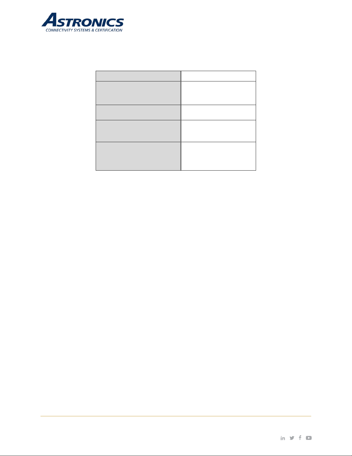
E71-314-101
Kit, Assembly
–OL Drawing
Base Unit –OL Drawing
(capacity)
Table 3-1: Sierra Kit Specific Drawing Information
Kit P/N
Kit
Description
Kit
Kit Component:
Assembly,
Kit Component:
Assembly,
Removable SSD –OL Drawing
Sierra Portable Server
1TB Removable SSD
E71-314-101-OL
E71-319-01-OL
E54-576-01-OL
(1 TB)
3.2 Hardware Architecture
The Sierra leverages a state-of-the-art, commercial enterprise-class Wireless Access Point (AP). The
AP selected for this appl ication is manufactured by Aruba Networ ks, a Hewlett Packard Enterprise
company, The Aruba model AP-303 has been ruggedized and repack aged to meet the operational
requirements of commercial aircraft environment.
The Sierra feature set includes:
• Utilizes a commercial dual band (2.4GHz/5GHz) 802.11ac, Wave 2 Access Point
• A dedicated 802.11ac/bgn r adio (2.4 GHz /5 GH z) for networking bet ween multiple Sierra
units
• Dual hot swappable batteries for over 12-hours of video streaming content
• Up to 2 TB of storage possible with front removable solid-state drive
• Can be powered optionally from a 18V external power outlet with the appropriate STC.
• ADS-B Receiver for streaming moving map applications
• 4G/LTE cellular radio. Automatically disables cellular modem based on aircraft ADSB data.
• Audio/Video content can be paused remotely via detecting a PA announcement
• Disables itself automatically in the event of an emergency decompression
Page | 15 Revision Date January 28, 2020 || Document Number UM-E71-314 || Rev A
astronics.com
Page 16
Component
Description
CPU Dual Core 1.3 GHz (1.8 MHz burst), Intel® Atom™ x5-E3930
16 GB eMMC onboard flash
Wi-Fi
Two (2) 2.4 GHz/5 GHz, 802.11ac/abgn radios (Wave 2) –
Cellular
4G/LTE supports diversity mode. Automatically enables and disables
transmission based upon ADSB data. Front Panel Auto/Override switch
functions (requires a complimentary BLE device installed on the aircraft).
ADS-B
ADS-B receiver; used for moving map applications and automatic cellular
modem control.
Decompression
Automatically disables IFE systems in the event of a cabin decompression
Security
TPM per TPM 2.0
Mass Storage
Front Removable: Up to 2 TB SSD
Front Panel
Power ON
Battery
Up to 2x 14.4 V, 6900 mA∙h (99.4 W∙h) Li-ion. Batteries are hot
Aircraft Power
Optionally can be powered via the aircraft 28 VDC power bus with slide in
Note: Requires use of an aircraft specific STC.
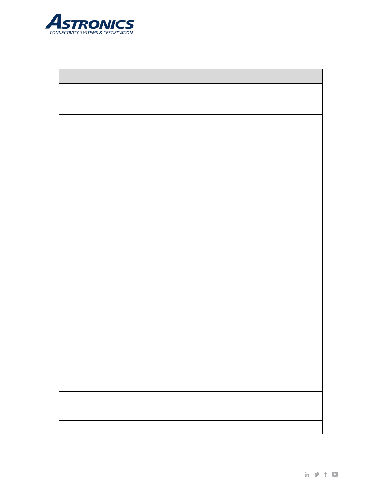
3.3 Key Hardware Components
The Sierra key hardware components include:
2 MB L2 cache
4 GB DDR4 – 2133MT/s
simultaneous operation.
One (1) dedicated 802.11ac/bgn (2.4 GHz/5 GHz) radio for networking
multiple units together.
Bluetooth Bluetooth v4.0 or Bluetooth Low Energy to be used for wireless discrete
PA Pause Optionally can automatically pause streaming content in the event of a PA
announcement.
Note: Requires a PA Pause Module, Astron ics CSC P/N E71-500-01,
installed in the aircraft.
Internal: 16 GB eMMC flash memory on board
Control
Interfaces
Power ON/OFF button
USB 3.0 (Type A)
SIM card slot (front panel)
Serial console applications for both CPU and AP (USB-C)
Gigabit Ethernet (RJ45 – rear panel)
External power source (DIN and blade connector – rear panel)
LED Indicators
Cellular Enabled
Bat 1 / Bat 2 State-of-Charge Indicators
Status
External Power Source
Bluetooth
Wifi
tray-mounted connector.
Dimensions 7.1” (W) x 10.4” (L) x 4.7” (H)
Page | 16 Revision Date January 28, 2020 || Document Number UM-E71-314 || Rev A
astronics.com
Page 17
Component
Description
Operating
Ubuntu 18.04 supported (support of other Linux systems available upon
CPU
4G/LTE
Cellular
Mo dem
SIM
Fr ont Pan el
Mai nten ance
Wi-F i /BLE
Cell
Dis/A uto
ADS-B
Rec v’r
USB
A
USB
C
Access Point
802.11ac/g/b/n
Pwr SW
ON/OFF
RSSD
Batt
1
Batt
2
Ext DIN Pwr
Connector
Front
Panel
R ear
Panel
Battery
Sta tus SW
LE Ds an d
Sw itch
Cell
Dis/A uto
Rea r P nl
Et hern et
RJ45
µH DMI
LE D
Sta tus
Aircraft Blade
Pwr Connector
Backplane
PCB A
19
V
So urce Ind .
Thermal Natural convection
Environment Operating: 0°C to +50°C
Storage w/o Batteries: -40°C to +85°C
Storage w/ Batteries: -20°C to +50°C (+25°C recommended)
System
request).
Figure 3-1 shows the Sierra System Block Diagram.
Figure 3-1: Sierra System Block Diagram
Page | 17 Revision Date January 28, 2020 || Document Number UM-E71-314 || Rev A
astronics.com
Page 18
E71-314-XXX
*
E54-576-XX
*
5
E71-500-01
PA Pause Assembly
Li-Ion Battery (purchase directly from RRC Power
Solutions)
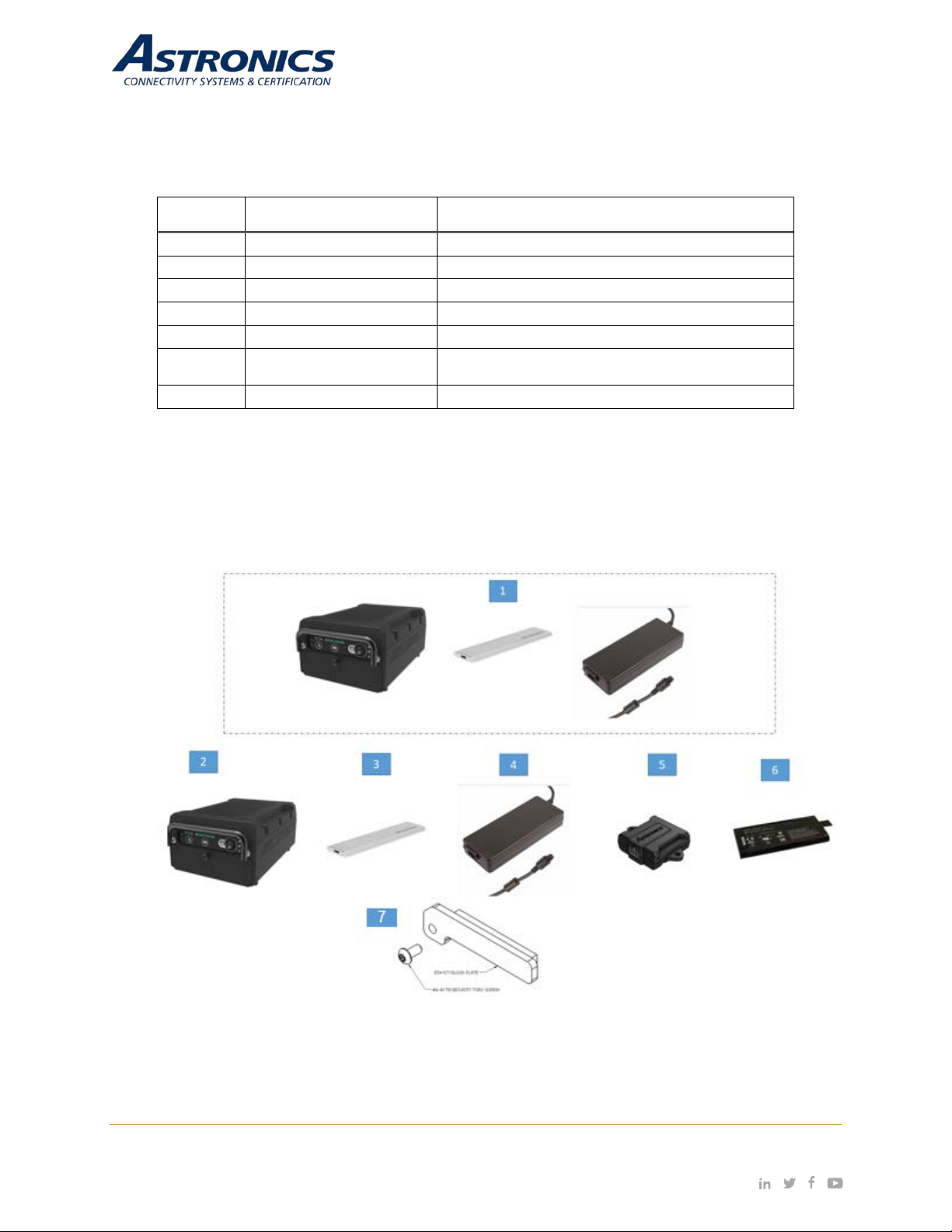
3.4 Orderable Part Numbers
Table 3-2: Sierra Orderable Part Numbers
ID Astronics CSC P/N Description
1
Kit, Sierra, Removable SSD
2 E71-319-01 Sierra Base Unit Assembl y
3
RSSD Module
4 AHM250PS19 External Power Module with Cable
6 RRC2054-2
7 E54-577 SSD Block Plate Kit
Notes:
*
See Table 3-1 for kit specific part numbers.
•
• Items 2, 3, and 4 are included in the Sierra Kit, Item 1, P/N E71-314-XXX.
• The wall plug interface cable is not included in Item 4.
• Installation kits are not listed above.
Page | 18 Revision Date January 28, 2020 || Document Number UM-E71-314 || Rev A
Figure 3-2: Sierra™ Equipment
astronics.com
Page 19
4 Powering Up
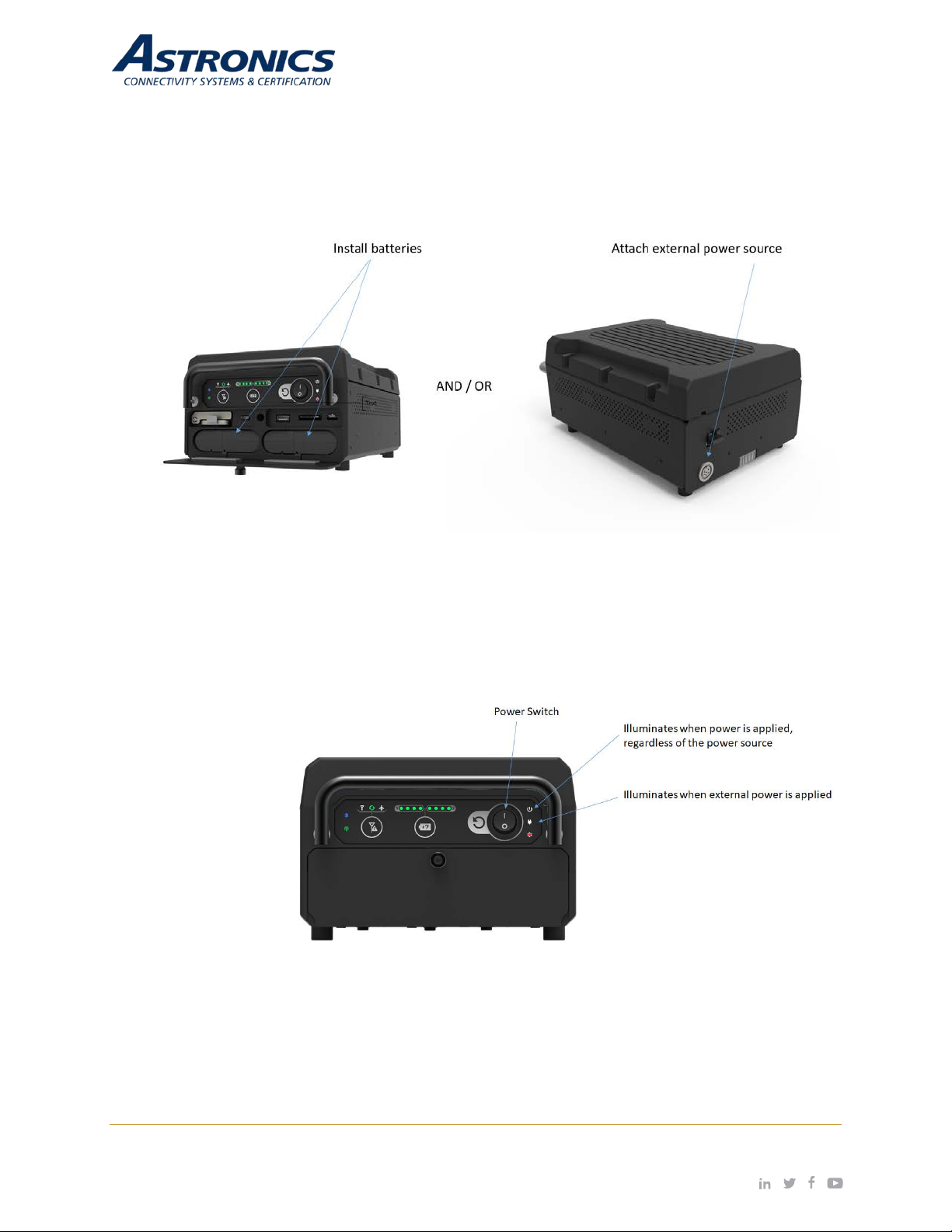
Two (2) high-density Lithium-ion (Li-ion) battery modules, RRC Power Solutions P/N RRC2054-2, are
required to power the Sierra. Altern atively, Sierr a can be po wered via the air craft 28VDC p ower bus w ith
the appropriate STC. Refer to Figure 4-1.
Figure 4-1: Power Source
Once power is con nected v ia batt eries or ext erna l po wer sour ce, turn the POWER switch to ‘ON’ position
as shown.
Figure 4-2: Power On/Off Switch and Power Indicator
Page | 19 Revision Date January 28, 2020 || Document Number UM-E71-314 || Rev A
astronics.com
Page 20
Port
Baud Rate
Data Bits
Parity
Stop Bits
Flow Control
CPU
115200
8 bit
none
1 bit
none
WAP
9600
8 bit
none
1 bit
none
Cell Modem
9600
8 bit
none
1 bit
none
5 Connecting to Sierra
5.1 Terminal Communication Settings
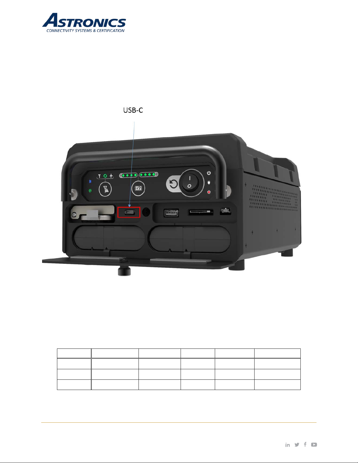
The integrated USB to UART provides console acces s via the US B-C port that is loc ated behi nd the
battery door as shown in Figure 5-1. There is also an internal console for the cell modem , when
enabled. Use these settings to connect to the consoles:
Figure 5-1: USB-C connection
Use these settings to connect to the consoles:
Table 5-1: Com Port Settings
Page | 20 Revision Date January 28, 2020 || Document Number UM-E71-314 || Rev A
astronics.com
Page 21
5.2 SSH
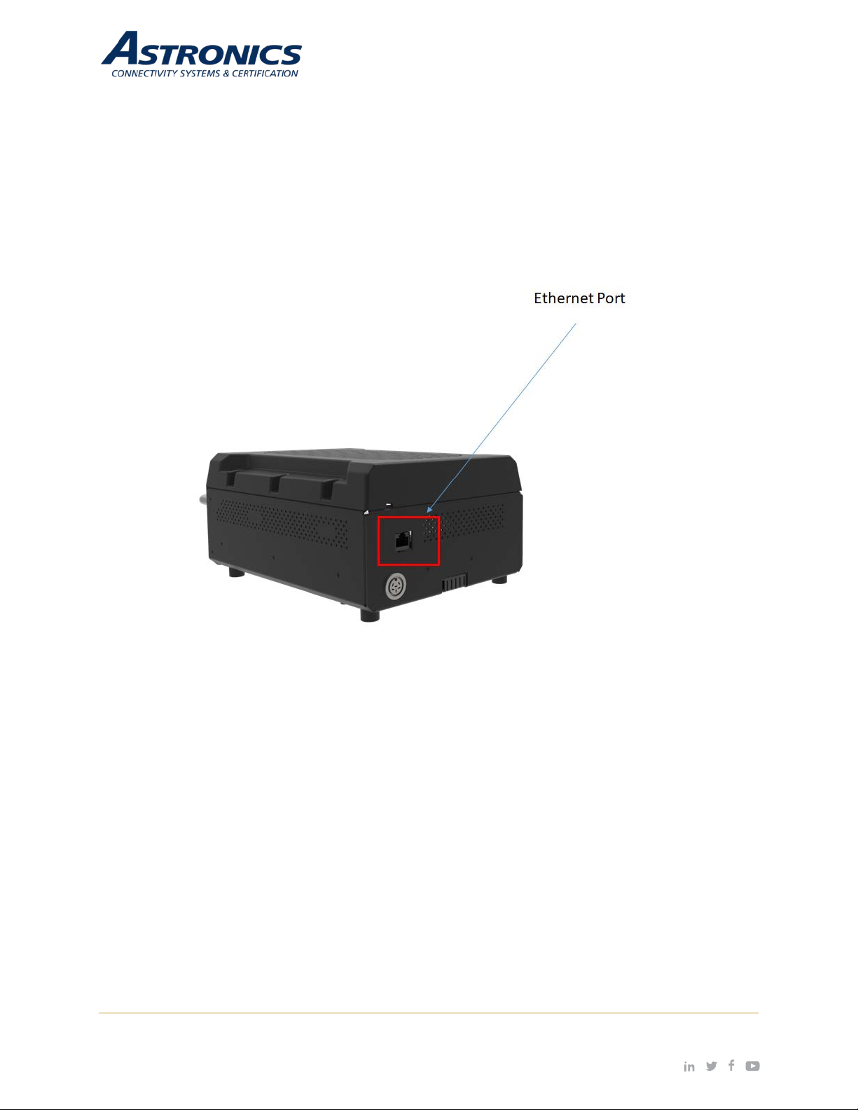
The rear Ethernet port c omes configured as a dhcp client to allow access to the s ystem from your
development network. You can ssh into the unit using the Sierra username and password.
User: sierra
Password: sierra
Figure 5-2: Ethernet Port
5.3 SSID
Sierra comes configured with the following ATP SSIDs, where xxxxxx is replaced with t he unit ’s se rial
number. The password for both is: 12345678
• xxxxxxw2p4ghz
• xxxxxxw5ghz
Page | 21 Revision Date January 28, 2020 || Document Number UM-E71-314 || Rev A
astronics.com
Page 22

5.4 WAP Configuration
Sierra leverages an Aruba enterprise class wireless access point that runs Aruba’s Instant virtual
controller software. The WAP can be configured through the Aruba web GUI, or through the
console/sssh comm and line interface (CLI). The se ttings can be saved out t o, and loaded from, a
configuration file.
The following example copies a configuration file to the tftp server:
sierra# copy config tftp 192.168.1.1 filename.cfg
The following example copies a configuration file to the WAP:
sierra# copy tftp 192.168.1.1 filename.cfg system config
reload (this command restarts the WAP)
To maximize video str eaming perform ance, the following sett ings have been incl uded in the default
configuration file: /var/lib/tftpboot/SierraBlackLabel.cfg
• Wide channel bands are enabled, but channel width has been limited to 40MHz. This helps
clients get on and off the air more quickly.
• Minimum transmit rates have been set to 12 Mbps. This prevents weaker clients from
slowing down the network.
• Arp Broadcast filtering is enabled. This converts arp broadcasts to unicast.
• ARM Band Steering Mode is set to Balance Bands. This helps utilize both radios.
• The min/max power settings of the 5 GHz radio ha ve been set 6d bm higher than the 2.4
GHz radio. This accounts for the additional free space path loss and smaller receiver
aperture associated with the higher frequencies.
Page | 22 Revision Date January 28, 2020 || Document Number UM-E71-314 || Rev A
astronics.com
Page 23
6 Connecting using Aruba’s Web-based GUI
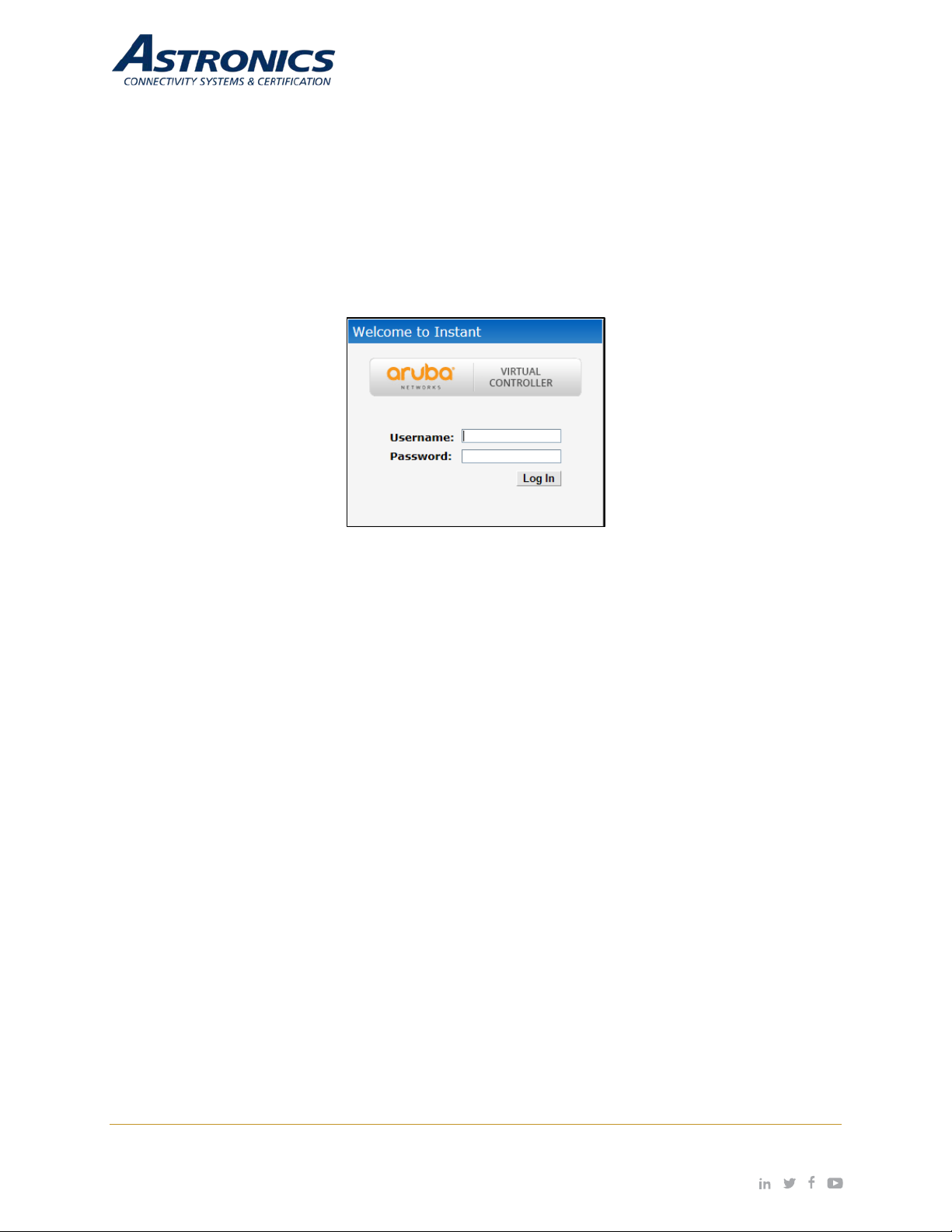
You can connect to the web-based GUI by entering the Aruba AP’s IP address 192.168.1.20 in a web
browser, and enter ing the Usernam e and Password (adm in / admin) when prom pted as shown bel ow in
Figure 6-1.
Note: The following s ubs ec tions ref er to the [Ar uba] I AP, or AP w hic h sha ll be u sed i ntercha ngeably wit h
the Sierra. The sections are summari zed from Aruba Instant documentatio n and training materials. For
additional information refer to the Aruba Instant User Guide.
Figure 6-1: Aruba Instant GUI Login Prompt
You may see a Certif icate Er ror m essage. T his is because th e cert ificates iss ued to th e AP do not m atch
the IP address used to connect to th e GUI. It is reco mmended that you add a certific ate issued by your
network, to ensure secure administrative communication.
The web interface main GUI page is broken up into three vertical bands (A, B, C).
Vertical bands
A. Virtual Controller - The top band cont ains the Virtual Controller settings, thes e are the global
settings.
B. System Components - This band contains the system components of the wireless network.
C. Information – This band displays information for the currently selected system component.
The main GUI page is brok en up into the following six sections. These s ections are identified below in
Figure 6-2.
1. Networks – Shows all the wireless networks associated with this cluster.
2. Acce ss Poin ts – Shows all the access points in the cluster, the * indicates the Virtual Controller.
3. Clients – Shows all the clients connected to access points in this cluster.
4. Instant AP information – Basic information on the Virtual Controller of this cluster.
5. RF Dashboard – Gives you a view of all clients RF signals and other issues.
6. Usage Trends – Shows all the clients and throughput generated by all the clients on this cluster.
Clicking on the + or – signs in the band or section title bar will expand or collapse that band or section.
Page | 23 Revision Date January 28, 2020 || Document Number UM-E71-314 || Rev A
astronics.com
Page 24
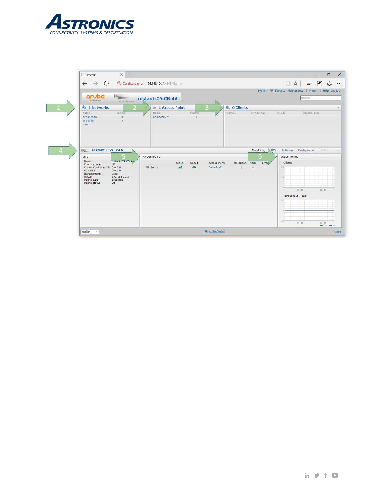
Clicking on the one of the Blue text items or Green icons will display details of that item.
Figure 6-2: The Six Sections of the Aruba Instant Main GUI Page
Page | 24 Revision Date January 28, 2020 || Document Number UM-E71-314 || Rev A
astronics.com
Page 25
6.1 Aruba Userna me and Pas sword
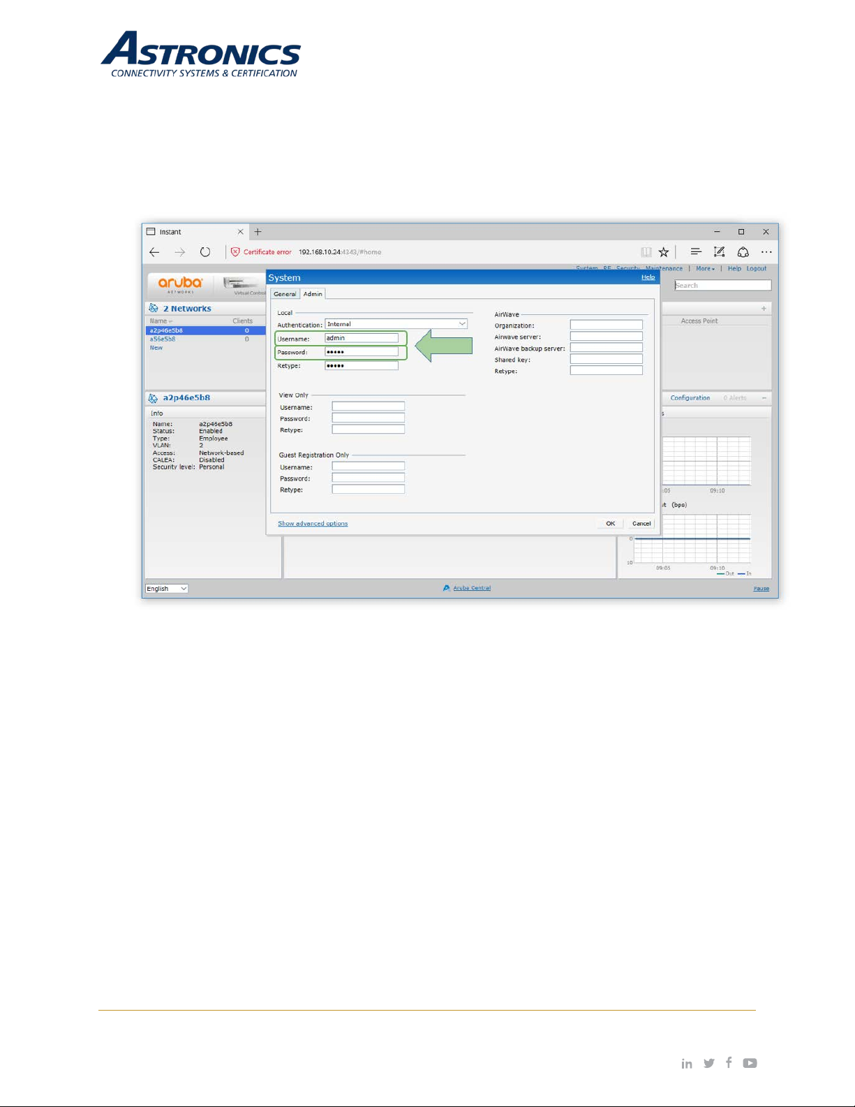
The default system username and password are admin / admin. It is recom mended that these be
changed. The s ystem username and pass word can be change d from the Admin tab of the System
dialog box, as show in Figure 6-3.
Figure 6-3: System Username and Password Dialog Box.
Page | 25 Revision Date January 28, 2020 || Document Number UM-E71-314 || Rev A
astronics.com
Page 26
6.2 Network Selection
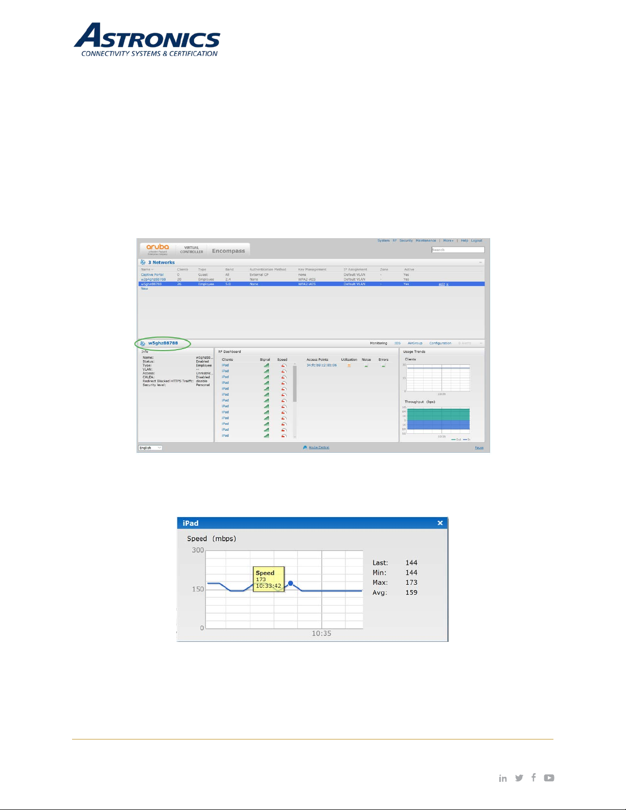
The Network section lists all the wireless networks (SSIDs) associated with the WAP, and displays the
number of clients cur rently connected to each SSID. Clicking on the “+” sign on the Network s ec tions
title bar will display addition information about the wireless networks as show below in Figure 6-4.
Selecting one of the Blue SSID names will show additional details in the Information band.
The Info section on the left side displays the general settings for the selected network.
The RF Dashboard sec tio n displ a ys a lis t of any clients experiencing signa l or spe ed is s ues. Clicking
on the speed icon brings up a popup window with further details as shown in Figure 6-5.
Figure 6-4: Additional Network Information
Figure 6-5: Signal Speed Popup Window
The Usage Trends s ection provides both cl ient, and throughput inform ation for t he selec ted wire less
network. in Figure 6-6, click ing on the thro ughput graph ope ns a po pup wind ow with a m or e detailed
graph.
Page | 26 Revision Date January 28, 2020 || Document Number UM-E71-314 || Rev A
astronics.com
Page 27
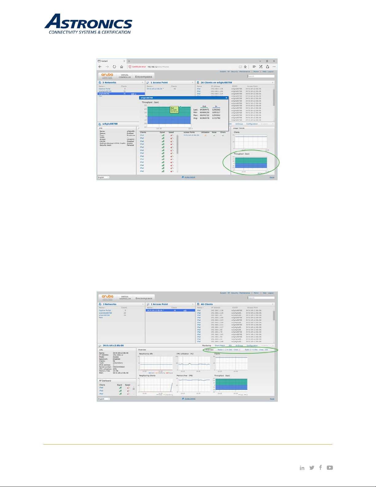
Figure 6-6: The Wireless network Usage Trends Section
6.3 Access Point Selection
The Access Points sect ion lists al l clients curr entl y connected to Sierra. You can selec t Access Point
to view its details i n the Information band as shown on Figure 6-7. On the left side of the Information
section are the operatin g details along with an RF Dashboard. On the right s ide of the Information
band is the Overvie w section, with monitoring graphs. On the right side of the Overview title bar we
see the Blue selectable text: Radio 1: 2. 4 GHz… and Radio 2: 5 GH z…. Selecting one of thes e text
items will display radio specific details as shown in Figure 6-8.
Figure 6-7: Information Band Display for Selected Access Point
Page | 27 Revision Date January 28, 2020 || Document Number UM-E71-314 || Rev A
astronics.com
Page 28
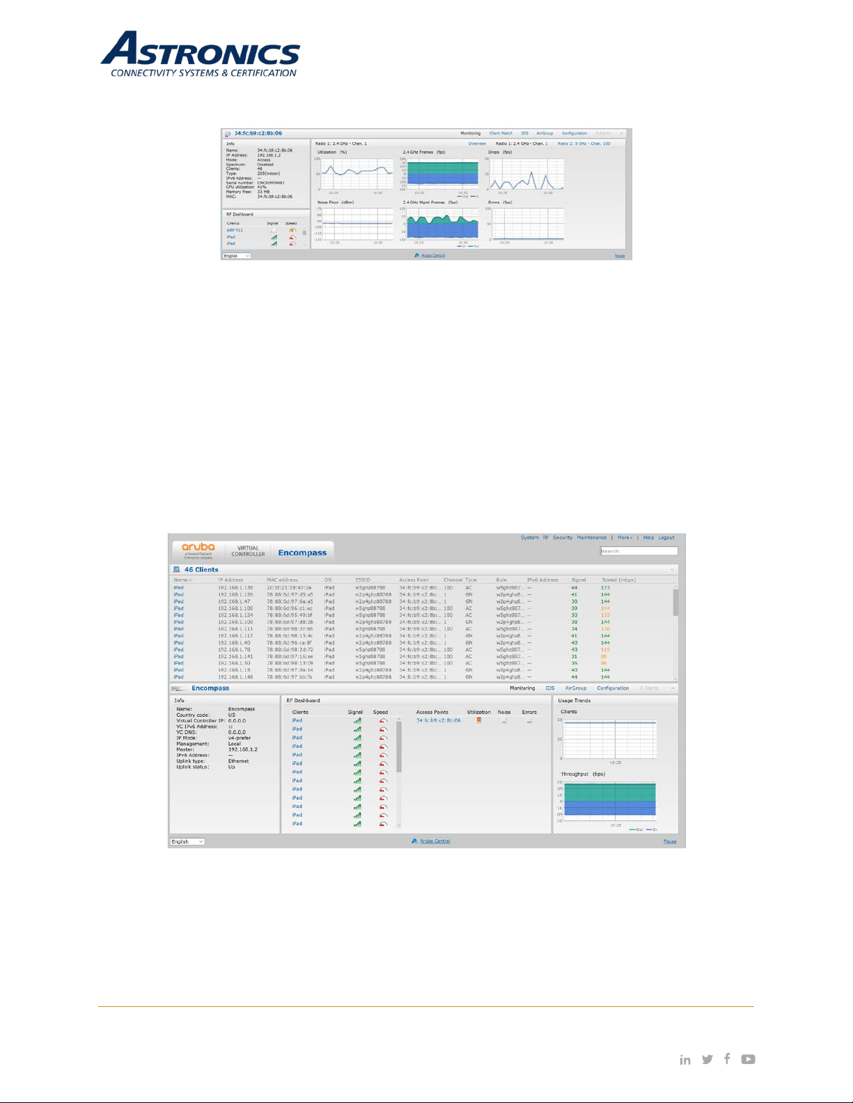
Figure 6-8: Radio Specific Details
6.4 Client Selection
The Clients section lists all the clients associated with the wireless network s. In the Clients section,
you can see the operating system and wireless capabilities of the devices, and also see which wireless
network the clients are associated with.
Figure 6-9 shows the detai ls of the Clients s ection. You can click on a client’s n ame to display the
details for that client in the Information band as shown in Figure 6-10.
Figure 6-9: Clients Section
Page | 28 Revision Date January 28, 2020 || Document Number UM-E71-314 || Rev A
astronics.com
Page 29
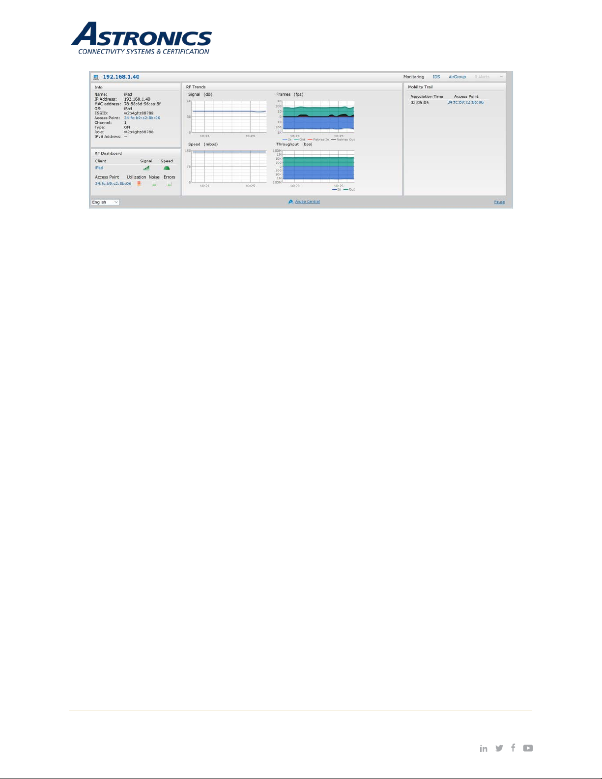
Figure 6-10: Client Details
Page | 29 Revision Date January 28, 2020 || Document Number UM-E71-314 || Rev A
astronics.com
Page 30
7 WLAN Setup
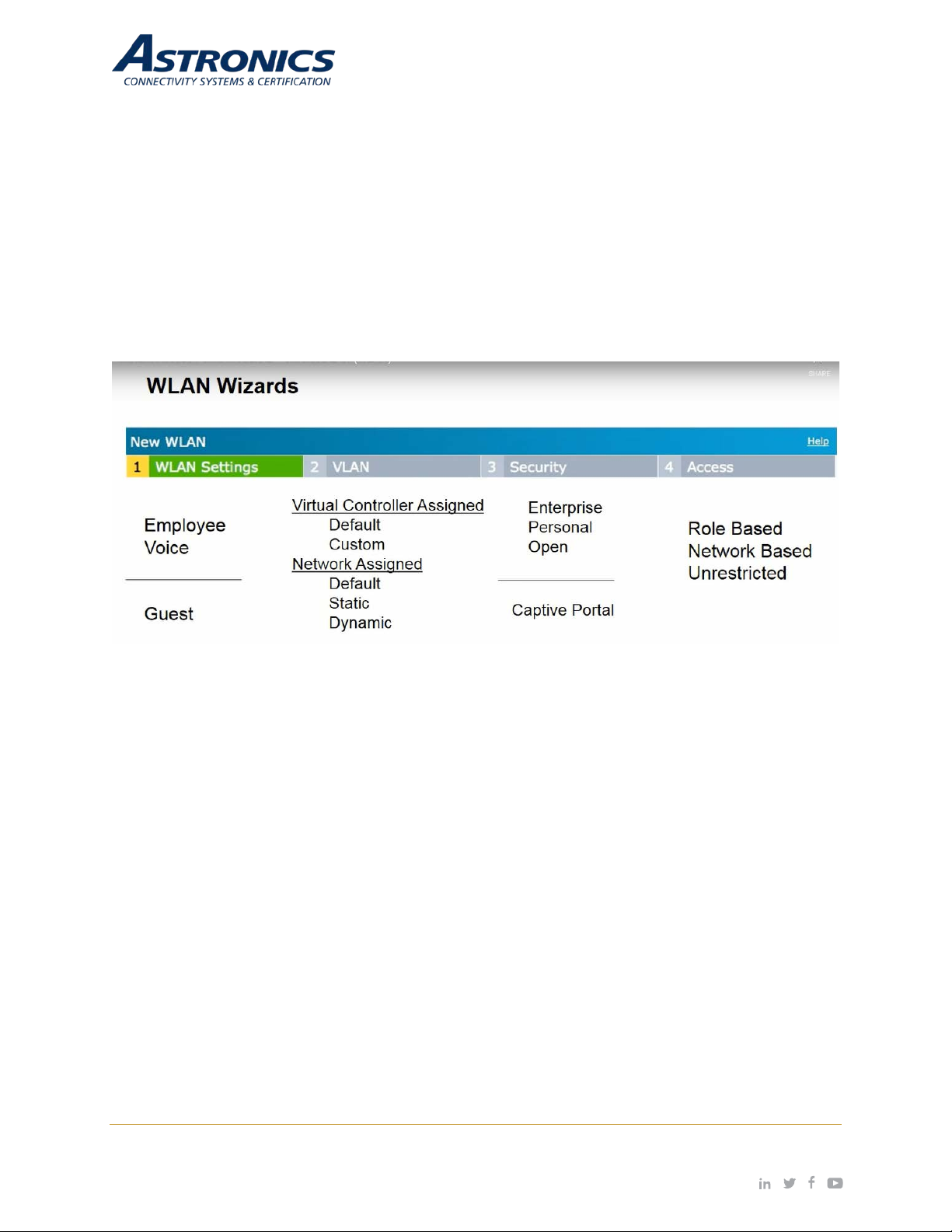
There are four steps to creating an SSID:
1. Selec t the type of SSID you want to create. T he Employee and Voice selec tions will lead you to
802.1X and PSK authentication. The Guest option will lead you to Captive Portal authentication.
2. Configure the Vlan and client IP assignment.
3. The security stage depends on your wireless LAN setting selections. Enterprise will give you 802.1x
selections, personal will give you PSK or WEP selections. If you select guest you will receive
captive portal options.
4. The last stage is the settings for the firewall with the user rights.
These stages are shown below in Figure 7-1.
Figure 7-1: The Four Stages to Creating an SSID
Page | 30 Revision Date January 28, 2020 || Document Number UM-E71-314 || Rev A
astronics.com
Page 31
Step 1
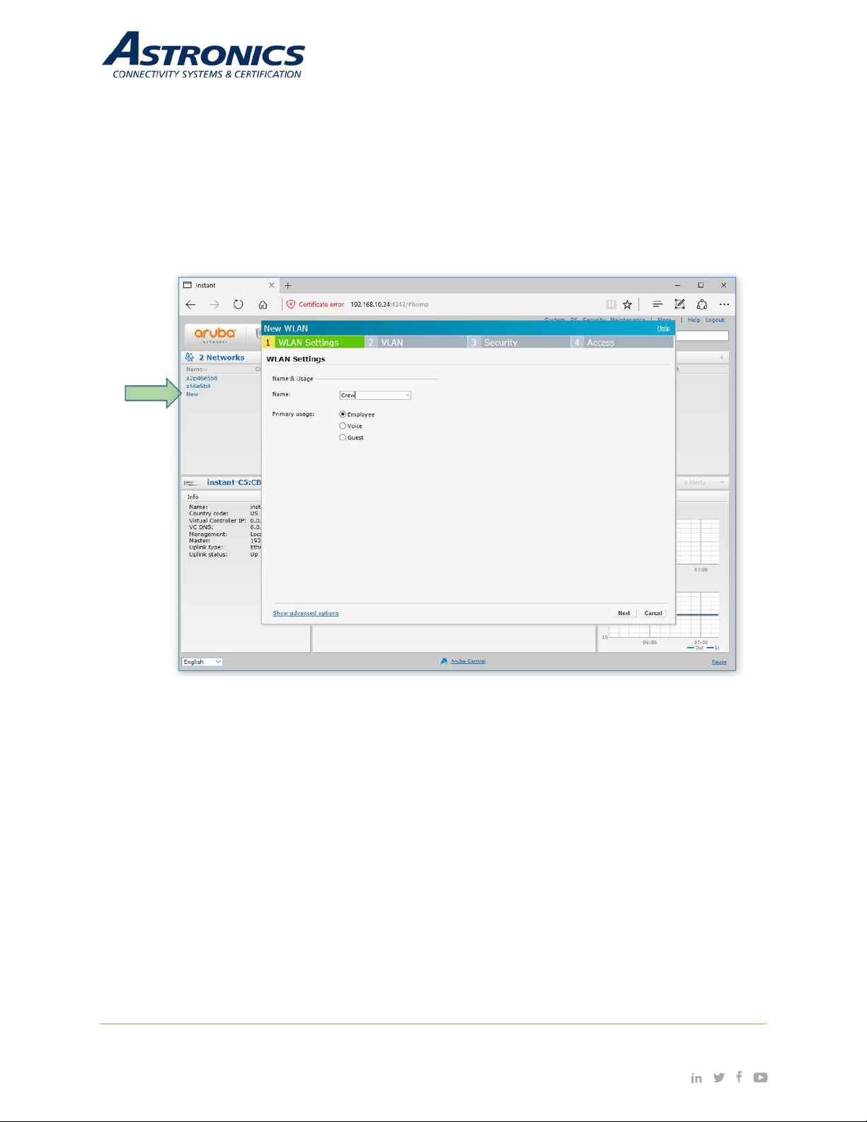
You create SSIDs us ing the WLAN W izard. You launch the WLAN Wizard by selecting New f rom the
Networks section on the main GUI page. This will bring up the WLAN Settings tab of the New WLAN dialog
box. The WLAN Settings tab is where you select the type of SSID you want to create and name the SSID,
as shown below in Figure 7-2.
Figure 7-2: The WLAN Settings Tab of the New WLAN Dialog Box
Page | 31 Revision Date January 28, 2020 || Document Number UM-E71-314 || Rev A
astronics.com
Page 32
Step 2
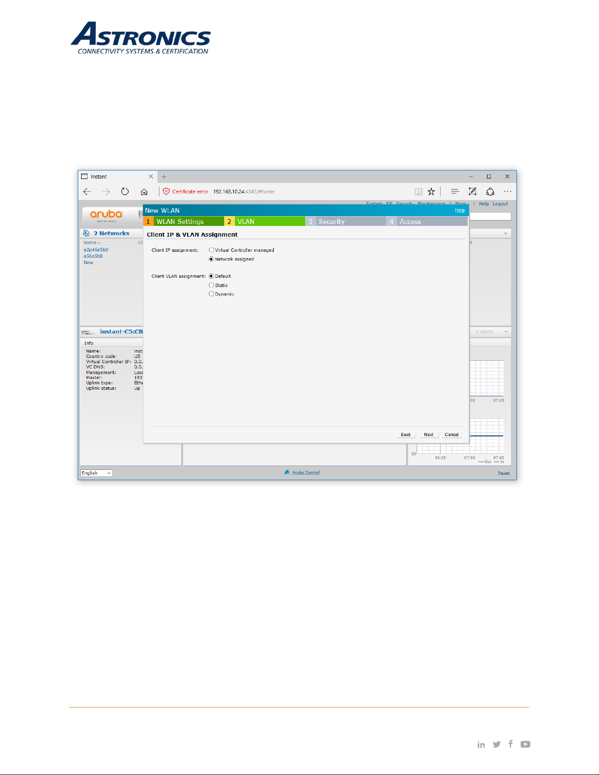
The VLAN Tab is where you configure the VLAN assignment and client IP assignment. The available
VLAN and client IP assignment options are shown below in Figure 7-3.
Figure 7-3: The VLAN Tab of the New WLAN Dialog Box
The two client IP assignment options are virtual controller Managed and Network assigned.
Virtual Controller Managed
The client will associate and authenticate to the access point. The access point will act as a relay agent to
the virtual controller, and the virtual controller will provide and act as the DHCP server.
• The Access Points will be providing DHCP for any wireless clients that connect to this SSID.
• The SSID and IAPs will source NAT all client traffic onto the wire.
Page | 32 Revision Date January 28, 2020 || Document Number UM-E71-314 || Rev A
astronics.com
Page 33
Network Assigned
The client will associate and authenticate to the access point. The access points will act as a bridge and
pass the traffic without modifying the original payload. DHCP will be provided by the DHCP server on the
LAN. The APs will bridge the client traffic onto the wire without manipulating or modifying the packets.
• The AP will bridge the client traffic onto the wire.
• The AP turns the wireless frame into an Ethernet frame.
Step 3
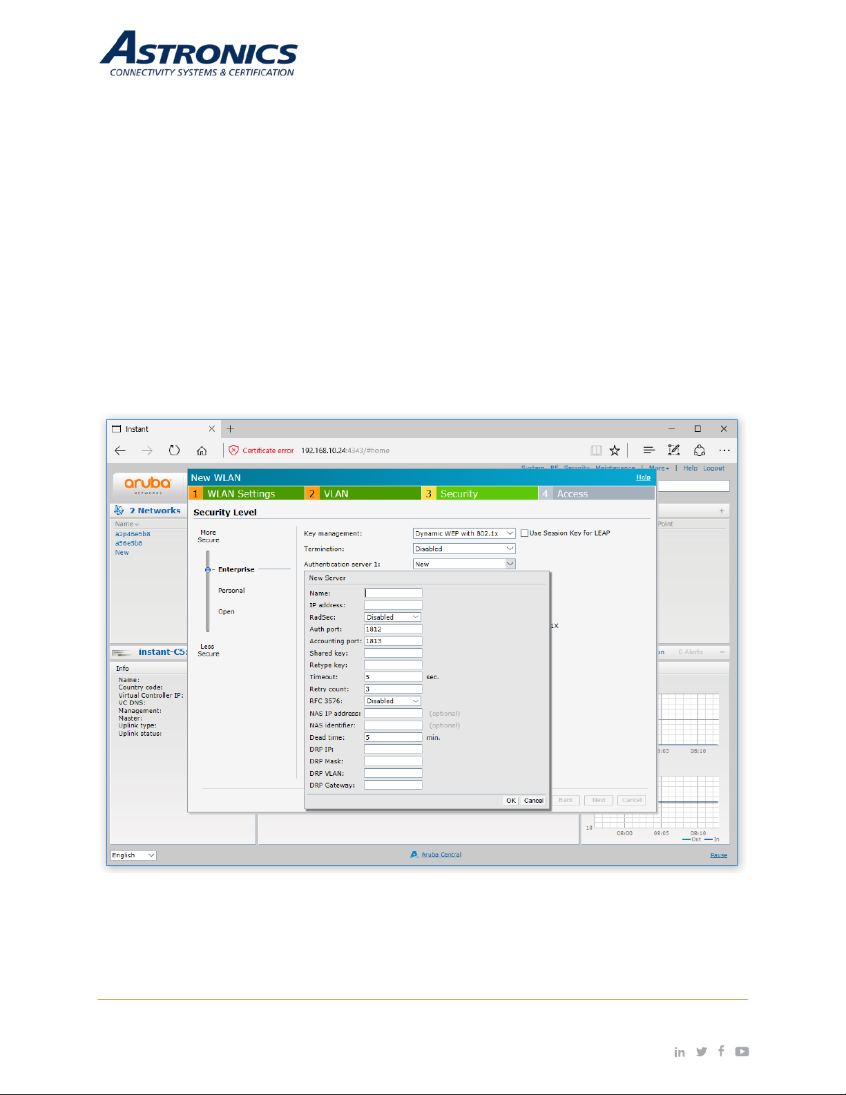
The Security tab is where you set the security level. There are three levels; Open, Personal, and Enterprise.
Selecting the Enterprise level allows you to configure an external RADIUS authentication server, as shown
below in Figure 7-4.
Figure 7-4: Configuring an External RADIUS Server
Page | 33 Revision Date January 28, 2020 || Document Number UM-E71-314 || Rev A
astronics.com
Page 34
Step 4
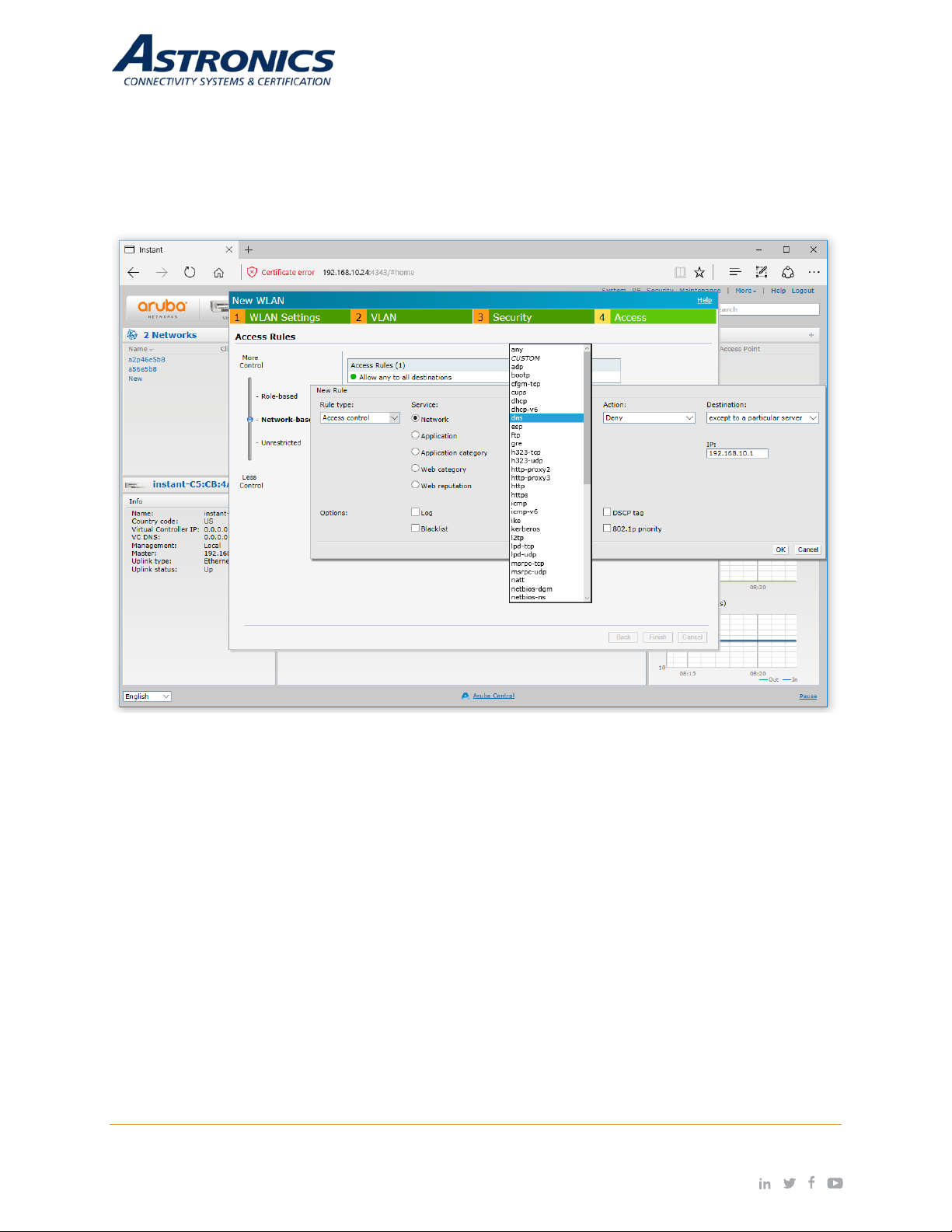
The Access tab is wher e you configure the fire wall rules and user rights. The Access tab allows you to
create Network-Based rules and Role-Based rules. You also have the option to leave the SSID Unrestricted.
Figure 7-5 sho ws an exam ple of creating a rule that deni es all DNS traf fic except to the DNS server with
the IP address of 192.168.10.1.
Figure 7-5: Configuring Firewall Rules
Refer to the Aruba Instant Users Guide for additional information on the IAP GUI.
Captive Portal SSID
The following is to create a Captive Portal SSID for your guests:
• In the WLAN Settings tab, select the Guest option.
• In the VLAN tab, select Netw ork Assign ed for Client IP Assignment and Default for Client VLAN
Assignment.
• In the Security ta b, select External for Splash Page Type, a nd then select the Edit button to edit
the default Captive Porta l P r ofile as shown below in Figure 7-6.
Page | 34 Revision Date January 28, 2020 || Document Number UM-E71-314 || Rev A
astronics.com
Page 35
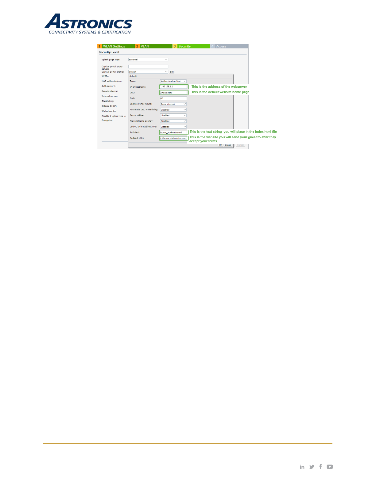
Figure 7-6: External Captive Portal Settings
• In the Access tab, configure the following Network Based Access Rule s:
o Allow HTTP to a specific server - 192.168.1.1
o Allow HTTPS to a specific server - 192.168.1.1
o Deny any to any
Place the following lines in the body of your index.html file which will automatically authenticate your guests.
<form>
<input type=”hidden” id=”authtext” value=Guest_Authenticated”>
</form>
Page | 35 Revision Date January 28, 2020 || Document Number UM-E71-314 || Rev A
astronics.com
Page 36
Switch / LED
Function
Power On/Off
8 User Interface
8.1 Switch and Display Panel
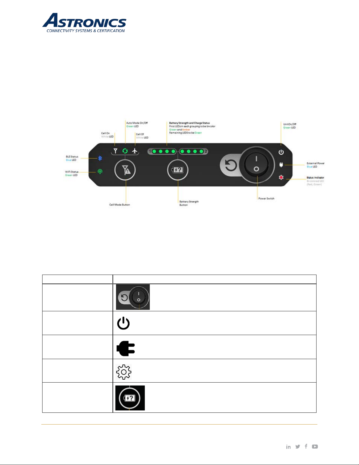
Sierra includes a visua l dis play and s witch pa nel locat ed on the f ront of the unit. T his panel i ncludes
series of LEDs and s witche s designed to pro vide the users with an int uitive int erface with the cr itical
functions of Sierra. Figure 8-1 is an annotated illustration of the front panel Switch and Display Panel.
Figure 8-1: Switch and Display Panel
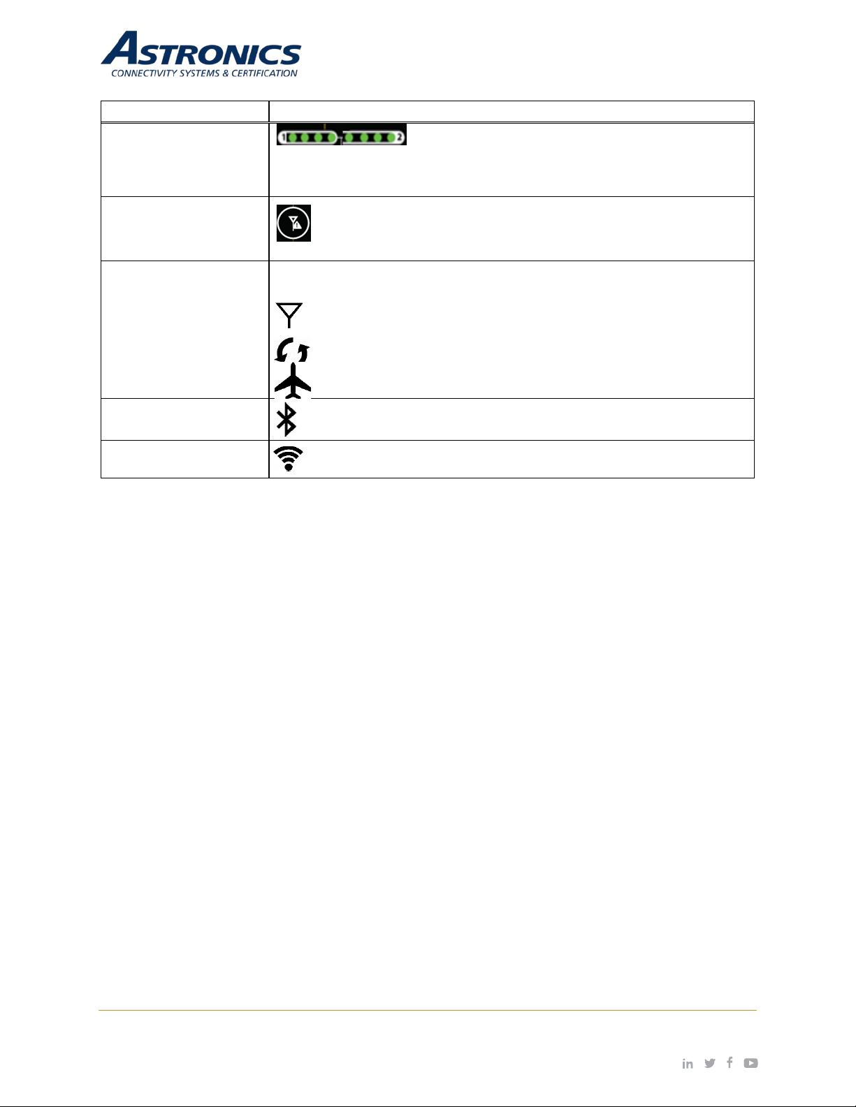
Table 8-1 lists the function of the front panel Switch and Display Panel.
Table 8-1: Switch and Display Panel Nomenclature and Function
Power S w it ch
Unit ON/Off LED
External Power LED
Status LED
Illuminates when power is applie d. Blinks while system is bootingup.
Illuminates whenever external power is applied.
Software programm able.
A momentary press displays the state-of-charge of each
Battery Strength Button
Page | 36 Revision Date January 28, 2020 || Document Number UM-E71-314 || Rev A
battery through an array of LEDs.
astronics.com
Page 37
Switch / LED
Function
description of the meaning and opera tio n.
operation.
Displays the cell modem mode of operation when the Cellular Mode button
Illuminates when Bluetooth is enabled and paired to an external
Battery Monitor LED
Display
battery has its own set of LEDs. The display illuminates for 4-seconds
when the Battery Strength button is pres s ed. See Sect ion 6.1. 6.4 for a
Cellular Mode Button
is pressed.
Cellular Mode
LED Icons
Bluetooth Status LED
Wi-Fi Status LED
Monitors the state of charge of batteries 1 and 2. Each
A momentary press cycles through each cell modem mode of
Illuminates when the cellular modem is ON.
Illuminates when the cellular modem is in “Auto” mode.
Illuminates when the cellular modem is “Off”.
discrete I/O device, e.g. the PA Pause module.
Illuminates when the Aruba Wi-Fi is enabled.
Page | 37 Revision Date January 28, 2020 || Document Number UM-E71-314 || Rev A
astronics.com
Page 38
8.2 Battery Status Indicator
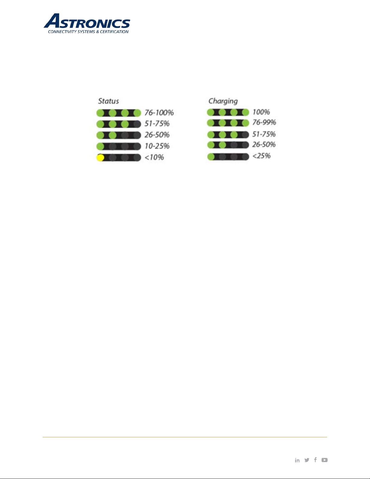
Sierra includes a front panel display to provide real-time battery State-of-Charge (SOC), and charging
status indications for Batt ery 1 and Batter y 2. Figure 8-2 describes the beha vior and meaning of the
display. The SOC of the installed battery modules (or battery in the case of one installed battery
module) is presented as four LEDs representing a “fuel gauge”. The display illuminates for 4 seconds
when the “Battery Status” switch is pressed.
Figure 8-2: Battery State-of-Charge Indicator
8.3 Cellular Mode Button
Both the main an d diversity antennas are integrated under the radom e of the unit. The m odem is
typically t urned of f w hen t he a ircr aft is airbor ne, both from an op erationa l s tandpo int an d to preser ve
battery power. Sierra is des igned to accept aircraft pos ition and/or ac celeration d ata to determ ine if
the aircraft is i n motion, and autom atically control the state of the modem. T he cell modem mode
button on the front panel can override this “Auto” feature and either turn the modem “OFF” or “ON”,
regardless of the operation of the aircraft.
8.4 Battery Door
To access the batter y bays, SIM card, SSD, and maintenance c onnectors behind the batter y door,
turn the knob (shown in Figure 8-3) counter-clockwise then open the battery door downward.
Page | 38 Revision Date January 28, 2020 || Document Number UM-E71-314 || Rev A
astronics.com
Page 39
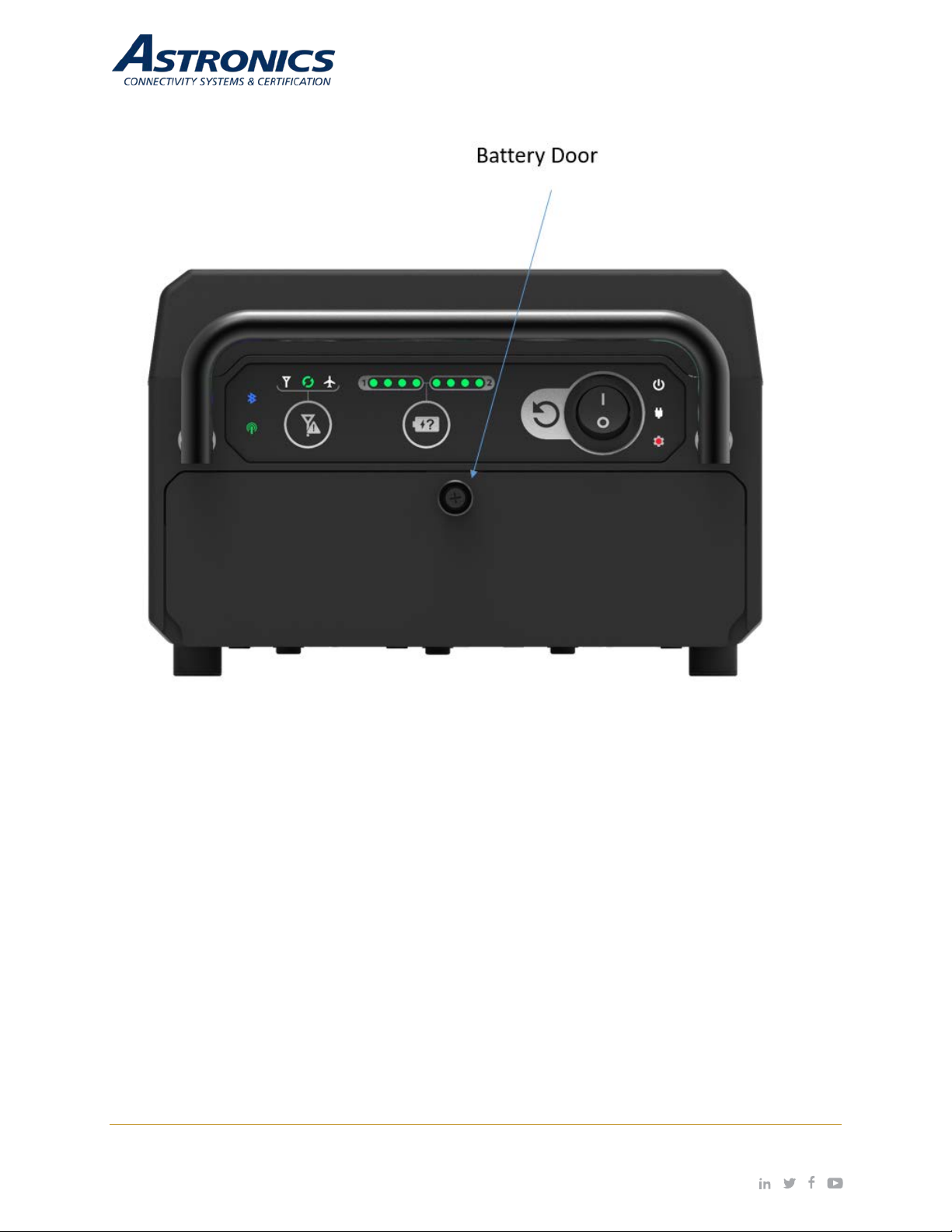
Figure 8-3: Battery Door
Sierra includes the following features behind the battery door:
• Removable Solid State Drive – 1TB m.2 SATA (default)
• Micro-HDMI port
• USB-C for serial console access to the CPU and access point
• USB 3.0 port
• SIM card slot
• Two battery bays
Page | 39 Revision Date January 28, 2020 || Document Number UM-E71-314 || Rev A
astronics.com
Page 40

Figure 8-4: Hardware Interface behind the battery door
Page | 40 Revision Date January 28, 2020 || Document Number UM-E71-314 || Rev A
astronics.com
Page 41

8.4.1 SSD Removal Instructions
Figure 8-5: Removable SSD Ejection Instructions
Page | 41 Revision Date January 28, 2020 || Document Number UM-E71-314 || Rev A
astronics.com
Page 42
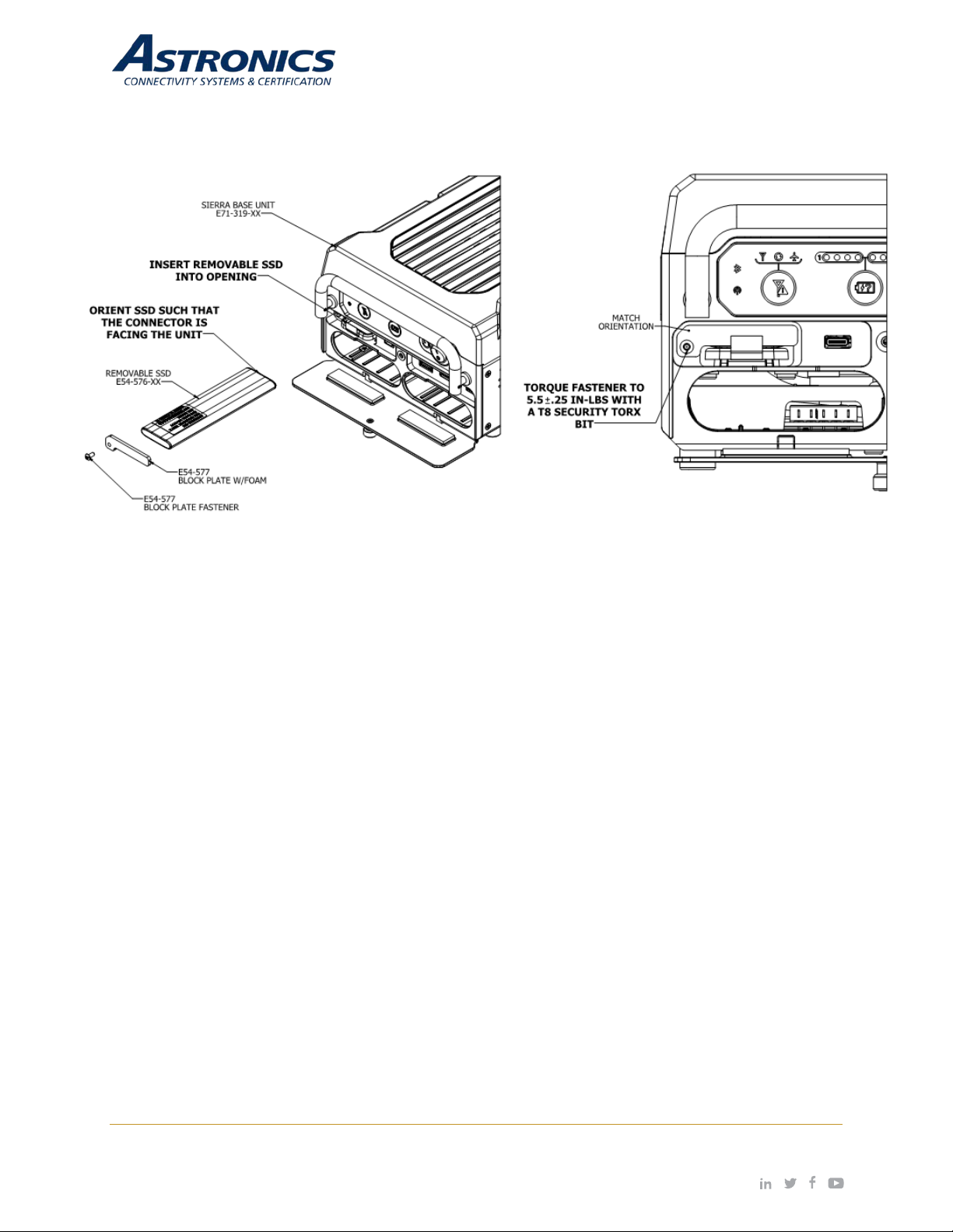
Note: The SSD Block Plate is intended as a theft deterrent device. Usage is optional.
Figure 8-6: Removable SSD Installation Instructions
Page | 42 Revision Date January 28, 2020 || Document Number UM-E71-314 || Rev A
astronics.com
Page 43
-2.400 to 2.4835 GHz
cannot be enabled by the end user or installer.)
Transmit Power Adjustment
Software configurable in increments of 0.5 dBm.
Maximum (aggregate, conducted total) transmit power
For total (EIRP) transmit power, add antenna gain + correlation gain.
802.11b: 1, 2, 5.5, 11
802.11n/ac packet aggregation: A-MPDU, A-MSDU
Two vertically polarized d ual-band downtilt omni-directional a ntennas
average (effective) pattern is 2.1dBi in 2.4GHz and 4.6dBi in 5GHz.
9 Performance Data
9.1 Aruba Wi-Fi Characteristics
Table 9-1: Radio Characteristics
Feature
Supported Frequency Bands
country-specific restrictions
apply
-5.150 to 5.250 GHz
-5.250 to 5.350 GHz
-5.470 to 5.725 GHz
-5.725 to 5.850 GHz (Note: This band disabled for use in EU and
Description
Operating Channels Dependent on configured regulatory domain.
Supported radio technologies
Supported Modulation Types
-802.11b: Direct-sequ enc e spr ead-spectrum (DSSS)
-802.11a/g/n/ac: Orthogonal frequency-division multiplexing (OFDM)
-802.11b: BPSK, QPSK, CCK
-802.11a/g/n/ac: BPSK, QPSK, 16-QAM, 64-QAM,256-QAM
(limited by local regulatory requirements):
Maximum Available Transmit
Power**
-2.4GHz band: +21 dBm (18 dBm per chain)
-5 GHz band: +21 dBm (18 dBm per chain)
-Note: conducted transmit power levels exclude antenna gain.
802.11a/g: 6, 9, 12, 18, 24, 36, 48, 54
802.11n: 6.5 to 300 (MCS0 to MCS15)
Supported data rates (Mbps)
802.11ac: 6.5 to 867 (MCS0 to MCS9, NSS = 1 to 2)
802.11n high-throughput (HT) support: HT20/40
802.11ac very high throughput (VHT) support: VHT20/40/80
for 2x2 MIMO with peak antenna gain of 3.3dBi (2.4GH z) and 5.9dBi
Wi-Fi Antennas
(5GHz) per antenna.
Combining the patterns of both antennas per radio, the peak gain of the
**The aggregate EIRP is limited to 20dBm (100mW).
Page | 43 Revision Date January 28, 2020 || Document Number UM-E71-314 || Rev A
astronics.com
Page 44
802.11b 2.4GHz
1 Mbps
18.0
-93.0
11 Mbps
18.0
-87.0
802.11g 2.4GHz
6 Mbps
18.0
-90.0
54 Mbps
16.0
-73.0
802.11n HT20 2.4GHz
MCS0/8
18.0
-90.0
MCS7/15
14.0
-71.0
802.11n HT40 2.4GHz
MCS0/8
18.0
-87.0
MCS7/15
14.0
-68.0
802.11a 5GHz
6 Mbps
18.0
-90.0
54 Mbps
16.0
-73.0
802.11n HT20 5GHz
MCS0/8
18.0
-90.0
MCS7/15
14.0
-71.0
802.11n HT40 5GHz
MCS0/8
18.0
-87.0
MCS7/15
14.0
-68.0
802.11ac VHT20 5GHz
MCS0
18.0
-90.0
MCS9
12.0
-67.0
802.11ac VHT40 5GHz
MCS0
18.0
-87.0
MCS9
12.0
-62.0
802.11ac VHT80 5GHz
MCS0
18.0
-84.0
MCS9
12.0
-59.0
Table 9-2: RF Performance Table
Maximum transmit power (dBm)
per transmit chain
Receiver sensitivity
dBm per receive chain
Note: Table shows the maximum hardware capabilities of the AP (excluding antenna and MIMO/MRC gain).
Actual maximum trans mit power may be limited below these numbers to ensure complianc e with local
regulatory requirements.
Page | 44 Revision Date January 28, 2020 || Document Number UM-E71-314 || Rev A
astronics.com
Page 45
Country
Code
Country
Code
Country
Code
Åland Islands
AX
Germany
DE
Nigeria
NG
Albania
AL
Ghana
GH
North Korea
KP
Algeria
DZ
Greece
GR
Northern Mariana
Islands
MP
American Samoa
AS
Greenland
G
Norway
NO
Andorra
AD
Grenada
GD
Oman
OM
Angola
AO
Guam
GU
Panama
PA
Antigua and Barbuda
AG
Guatemala
GT
Papua New Guinea
PG
Argentina
AR
Guernsey
GG
Paraguay
PY
Armenia
AM
Haiti
HT
Peru
PE
Aruba
AW
Honduras
HN
Philippines
PH
Australia
AU
Hong Kong
HK
Poland
PL
Austria
AT
Hungary
HU
Portugal
PT
Azerbaijan
AZ
Iceland
IS
Puerto Rico
PR
Bahamas
BS
India
IN
Qatar
QA
Bahrain
BH
Indonesia
ID
Republic of Korea
(South Korea)
KR
Bangladesh
BD
Iran
IR
Reunion
RE
Barbados
BB
Iraq
IQ
Romania
RO
Belarus
BY
Ireland
IE
Russia
RU
Belgium
BE
Islamic Republic of
Pakistan
PK
Saint Barthelem y
BL
Belize
Z
Isle of Man
IM
Saint Helena
SH
Bermuda
BM
Israel
IL
Saint Kitts and Nevis
KN
Bolivia
BO
Italy
IT
Saint Lucia
LC
Bonaire, Sint
Eustatius and Saba
BQ
Jamaica
JM
Saint Martin
MF
Bosnia and
Herzegovina
BA
Japan
JP
Saint Pierre and
Miquelon
PM
Botswana
BW
Jersey
JE
Saint Vincent and the
Grenadines
VC
Brazil
BR
Jordan
JO
Samoa
WS
Brunei Darussalam
BN
Kazakhstan
KZ
San Marino
SM
Bulgaria
BG
Kenya
KE
Saudi Arabia
SA
Cambodia
KH
Kuwait
KW
Senegal
SN
Cameroon
CM
Laos People's
Democratic Republic
LA
Serbia
RS
Canada
CA
Latvia
LV
Serbia and
Montenegro
CS
Chad
TD
Lebanon
LB
Singapore
SG
Chile
CL
Liberia
LR
Slovak Republic
SK
Country
Code
Country
Code
Country
Code
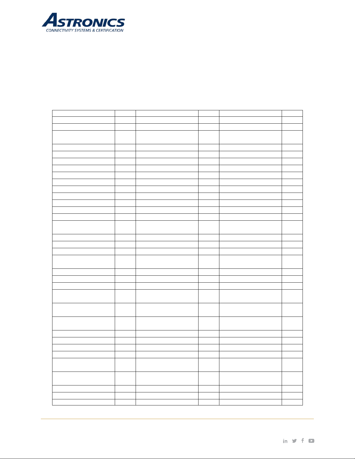
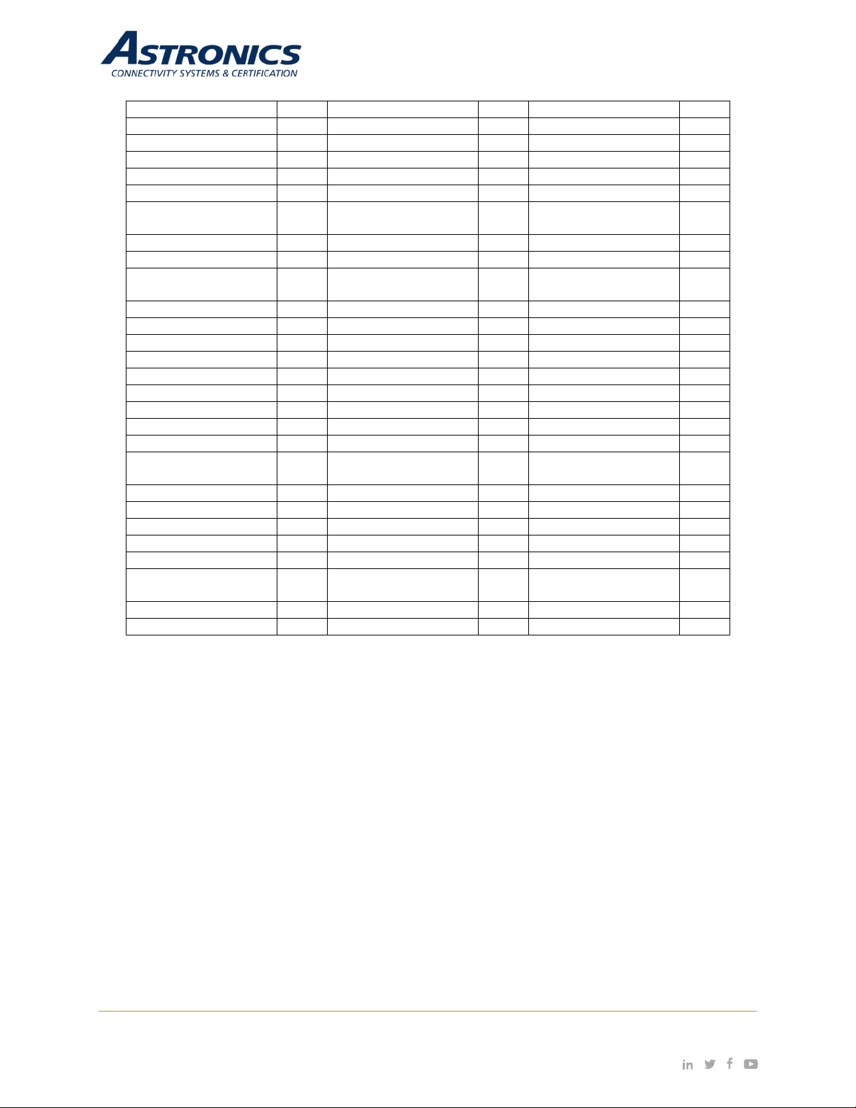
9.2 Country Codes
The IEEE 802.11/b/g/n Wi-Fi networks operate in the 2.4GHz spectrum and IEEE 802.11a/n operates
in the 5.0GHz spectrum. The spectrum is divided i nto channels. The 2.4GHz spect r um is divided into
14 overlapping, staggered 20 MHz wireless carrier channels. These channels are spaced 5 MHz apart.
The 5GHz spectrum is divided into more c hannels. The channels that can be used in a particular
country differ based on the regulations of that country.
Table 9-3: Country Codes
Page | 45 Revision Date January 28, 2020 || Document Number UM-E71-314 || Rev A
astronics.com
Page 46
China
CN
Liechtenstein
LI
Slovenia
SL
Colombia
CO
Lithuania
LT
Solomon Islands
SB
Comoros
KM
Luxembourg
LU
Somalia
SO
Congo
CD
Macau
MO
South Africa
ZA
Costa Rica
CR
Macedonia
MK
Spain
ES
Cote D'Ivoire
CI
Malaysia
MY
Sri Lanka
LK
Croatia
H
Maldives
MV
Svalbard and Jan
Mayen
SJ
Cuba
CU
Mali
ML
Sweden
SE
Curacao
CW
Malta
MT
Switzerland
CH
Cyprus
CY
Maritime Forward
Operating Base
MB
Syrian Arab Republic
SY
Czech Republic
CZ
Maritime Offshore
MMI
Taiwan
TW
Denmark
DK
Marshall Islands
MH
Thailand
TH
Dominican Republic
DO
Martinique
MQ
Trinidad and Tobago
TT
Ecuador
EC
Mauritania
MR
Tunisia
TN
Egypt
EG
Mauritius
MU
Turkey
TR
El Salvador
SV
Mayotte
YT
Uganda
UG
Estonia
EE
Mexico
MX
Ukraine
UA
Ethiopia
ET
Monaco
MX
United Arab Emirates
AE
Faroe Islands
FO
Mongolia
MC
United Kingdom
GB
Federated States of
Micronesia
FM
Montenegro
ME
United States
US
Fiji
FJ
Montserrat
MS
Uruguay
UY
Finland
FI
Morocco
MA
US Virgin Islands
VI
France
FR
Nepal
NP
Uzbekistan
UZ
French Guiana
GF
Netherlands
NL
Vatican City
VA
French Polynesia
PF
New Caledonia
NC
Venezuela
VE
French Southern
Territories
TF
New Zealand
NZ
Vietnam
VN
Gambia
GM
Nicaragua
NI
Yemen
YE
Georgia
GE
Niger
NE
Zimbabwe
ZW
Page | 46 Revision Date January 28, 2020 || Document Number UM-E71-314 || Rev A
astronics.com
Page 47
DO-160G
-
DO-160G
Yes
Test2)
DO-160G
Yes
DO-160G
4.6.1
Yes
DO-160G
4.6.2
Yes
DO-160G
Yes
DO-160G
Yes
DO-160G
Yes
DO-160G
Yes
IEC 61000-4-2
DO-160G
Yes
10 Technical Data
10.1 Electrical and Environmental Specifications
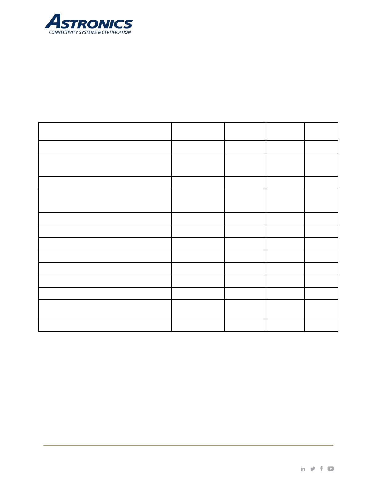
The Sierra unit com plies with all app licable FAA g uidelines and re gulations for a Portable E lectronic
Device (PED), and as such, is exempt from requiring formal RTCA/DO-160 airworthiness testing.
Sierra meets the electrical and environmental test categories per Table 10-1.
Table 10-1: Engineering Test Matrix
Test Description Specification Section Category Required
Temperature1
Ground Survival Low Temperature Test
(no Short Time Operating Low Temperature
2
)
Test
Operating Low Temperature Test3
Ground Survival High Temperature Test
(no Short Time Operating High Temperature
Operating High Temperature Test4
Altitude
Decompression
1, 5
Temperature Variation
Humidity
Operational Shock
DO-160G
DO-160G
4 -
4.5.1 A1
4.5.2 A1
4.5.3 A1
4.5.4 A1
A1
A
5.3.1 B
6.3.1 A
7.2.1 A
Yes
Yes
Vibration - Random
Electrostatic Discharge (ESD)
Fire, Flammability
Methods
8 S (Curve B2)
26 C
Yes
Notes:
1
All temperature testing was performed with a shroud per ARINC 628 part 7.
2
Not testing Short-Time Operating Low Temperature and Short-Time Operating High Temperature since
temperature limits required are outside of the operating limit of the Sierra, as designed.
3
Modified the DO-160G, Section 4.5.2, Category A1, Operating Low Temperature, limit to -15oC to 0oC,
as designed and described in the product specification, PS-E71-314.
4
Modified the DO-160G, Section 4.5.4, Category A1, Operating High Temperature, limit from +55oC to
o
C, as designed and described in the product specification, PS-E71-314.
50
5
Modified to perform only one cycle of the temperature profile.
Page | 47 Revision Date January 28, 2020 || Document Number UM-E71-314 || Rev A
astronics.com
Page 48
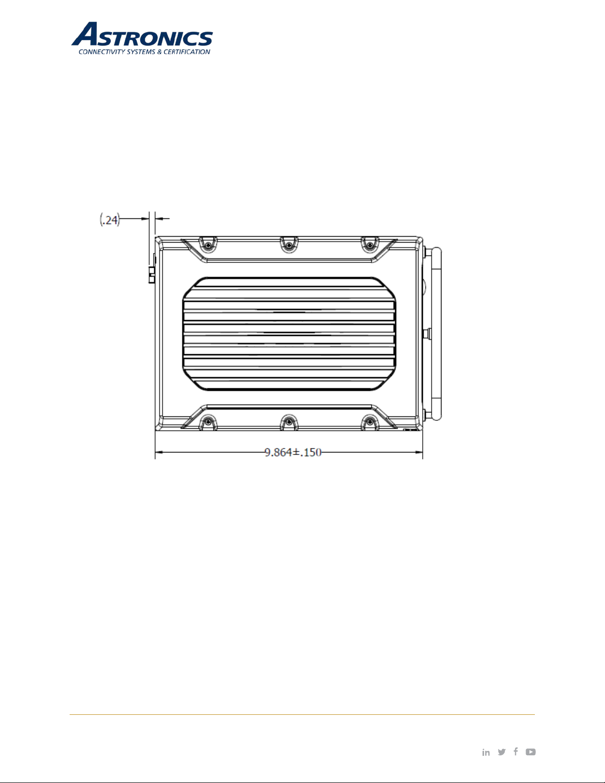
10.2 Mechanical Design and Dimensions
The Sierra’s metal components include a pr oper finish to of fer maintenance-free service over the life
of the Sierra. The Sierra’s internal chassis, circuit cards, wiring and cabling, and other major
components are mounted and secured to provide maximum protection agains t imposed shock and
vibration.
10.2.1 Top View
Figure 10-1: Sierra Top View
Page | 48 Revision Date January 28, 2020 || Document Number UM-E71-314 || Rev A
astronics.com
Page 49
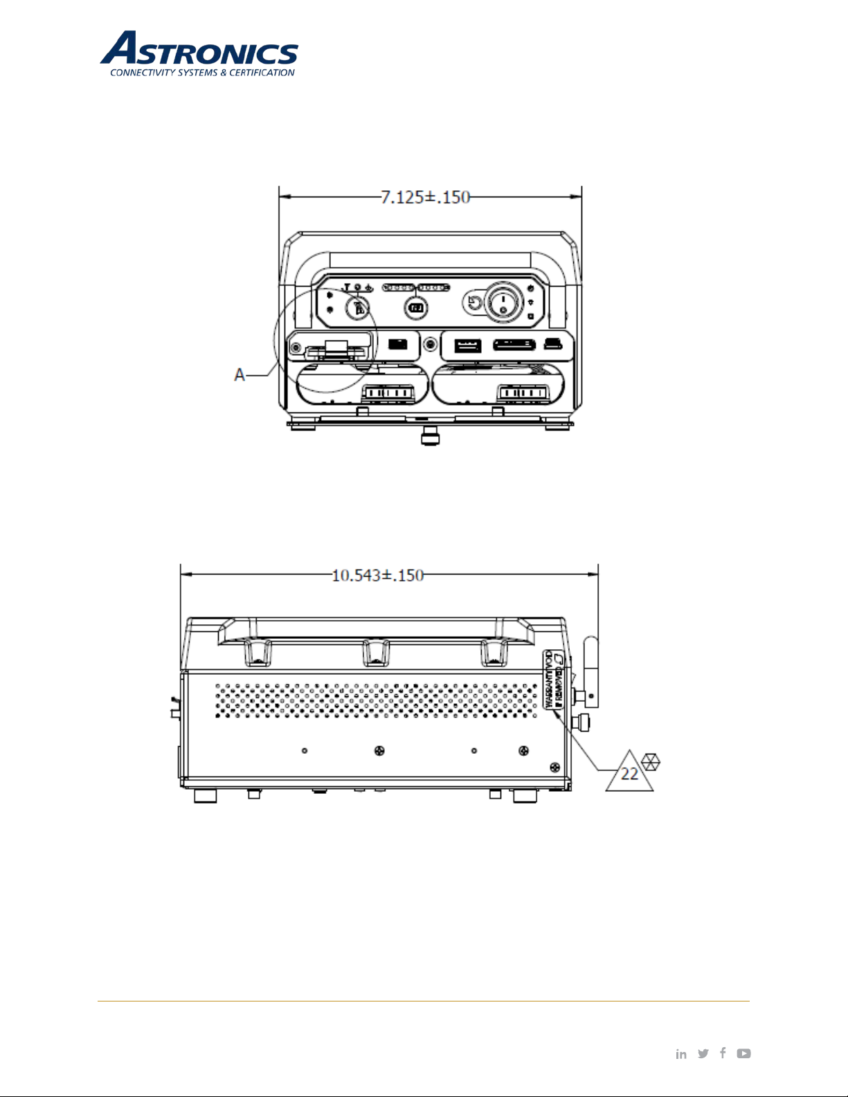
10.2.2 I/O Front View
10.2.3 Side View
Figure 10-2: Sierra I/O Front View
Figure 10-3: Sierra Side View
Page | 49 Revision Date January 28, 2020 || Document Number UM-E71-314 || Rev A
astronics.com
Page 50
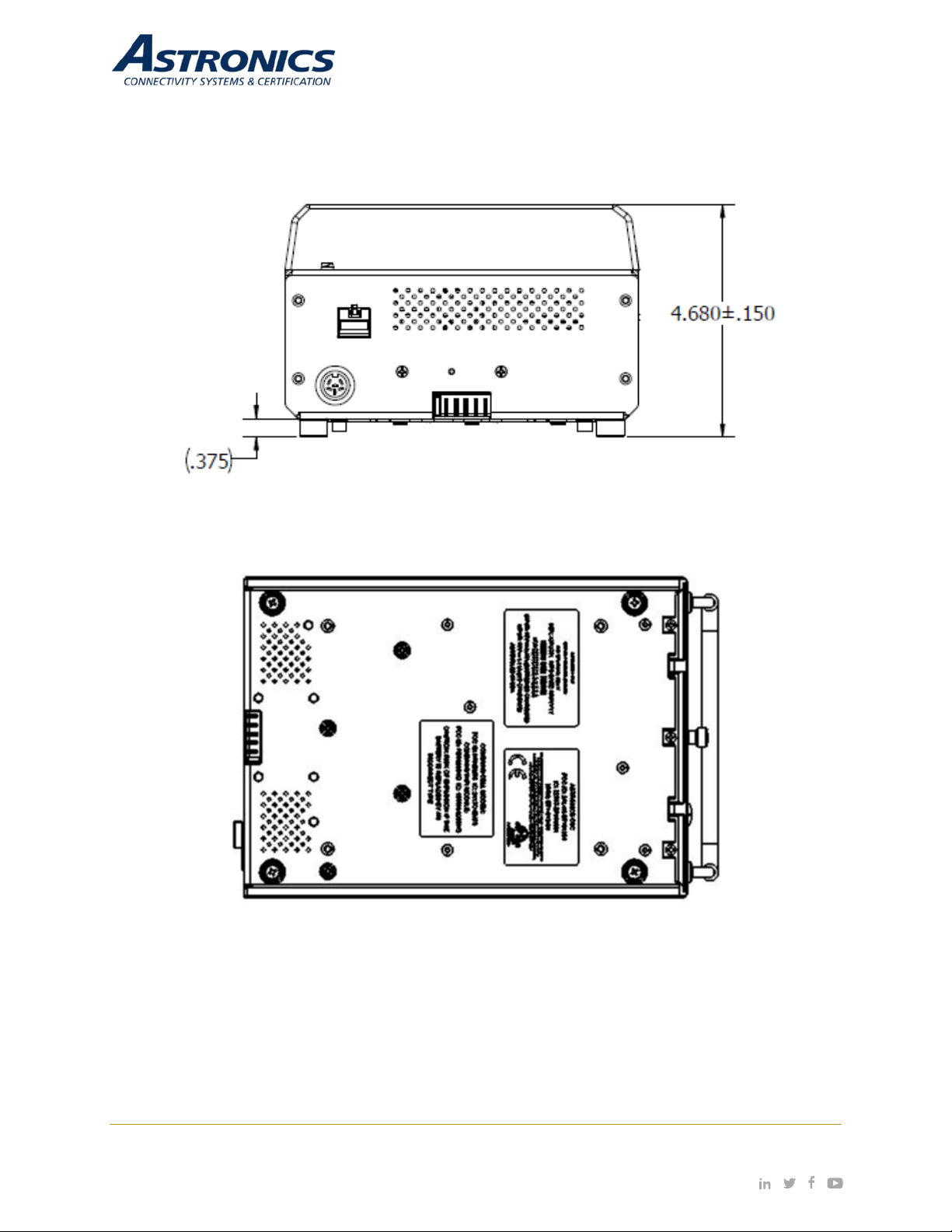
10.2.4 Rear View
10.2.5 Bottom View
Figure 10-4: Sierra Rear View
Figure 10-5: Sierra Bottom View
Page | 50 Revision Date January 28, 2020 || Document Number UM-E71-314 || Rev A
astronics.com
Page 51

10.2.6 Product Identification
The Part Number Identification Label f or each Sierra LRU is located on bottom panel and contains
information as shown in Figure 10-5.
10.2.7 Finish and Color
The paint color of the Sierra is medium texture black.
10.2.8 Materials
All materials used in the c onstruction of the Sierra are inherentl y non-nutrient to fungus and do not
support combustion. T he materials are of the best commercial qua lity and will not blister, corrode,
crack, soften, or show other immediate latent defects that affect the storage, operation, or
environmental capabilities of the unit after any or all of the tests specified.
Materials used in the Sierra have been selected in accordance with the appropriate flammability
requirements of Code of Federal Regulations FAR-25.853a.
10.2.9 Weight
The Sierra weighs 7.3 lbs, which includes a full complement of two (2) Li-ion battery modules.
10.2.10 Cooling Characteristics
The Sierra is designed with passive cooling.
• Battery Powered:
Power Consumption: 15.76W nominal, 17.65W max
Current Draw: 1.09A nominal, 1.23A max
Input Voltage: 14.4V nominal
• Installation Powered (batteries not charging):
Power Consumption: 15.76W nominal, 17.65W max
Current Draw: 0.88A nominal, 0.98A max
Input Voltage: 18V nominal
• Installation Powered (with batteries charging):
Power Consumption: 178.0W nominal, 179.9W max
Current Draw: 9.89A nominal, 9.99A max
Input Voltage: 18V nominal
• AHM250PS19 Supply Powered (with batteries charging):
Power Consumption: 178.0W nominal, 179.9W max
Current Draw: 9.37A nominal, 9.47A max
Input Voltage: 19V nominal
Page | 51 Revision Date January 28, 2020 || Document Number UM-E71-314 || Rev A
astronics.com
Page 52

10.2.11 Installation Limitations
The Sierra is intended t o be ins tal led in t he bag bin of the cabin to pro vide ad equ ate RF co verage of
the Wi-Fi signal. The Sierra shall maintain a minimum air gap spacing as follows:
• Bottom (G1) = 0.00”
• Left (G2) = 1.00”
• Right (G3) = 1.00”
• Top (G4) = 1.00”
• Front (G5) = 1.00”
• Rear (G6) = 1.00”
Installations violating the above air gap spacing must be approved by Astronics CSC engineering.
There are no minimum installation distances between Sierras. The maximum distance shall be
determined by aircraft type and configuration and content (e.g. throughput considerations).
Enclosures that fully encase the unit should be manufactured from materials that do not interfere with
the operation of the un it's a ntennas. Tr ansportab le en closur es suc h as bags s hould include sp acer s
to ensure these minimum air gaps are maintained at all times.
The air gaps listed above represent minimum required distances between the Sierra's surfaces and a
hypothetical enclos ure to ensure con tinued operatio n without overheat ing. Additional c onsideration
should be given to the unit's front face to allow for access to the unit's battery bays, peripheral
connections and the removable SSD if these elements are to be used while the unit is secured on the
aircraft. The front door of the unit requires 1.75" of unobstructed area to open fully, and the batteries
require a minimum of 6" of unobstructed area to be installed or removed. Allowance for these
additional clearances may be satisfied by the addition of a door or a removable cover to the enclosure
design.
Page | 52 Revision Date January 28, 2020 || Document Number UM-E71-314 || Rev A
astronics.com
Page 53

10.3 Workmanship
Workmanship, including ANSI/IPC-A-620 soldering, is designed to meet ANSI/J-STD-002 and
RTCA/DO-254.
10.4 Safety
The Sierra includes fuses on the system input power lines (Shurter Inc. P/N: 3413.0331.22, 63V, 20A),
as well as additional fuses on the input power lines to the main system circuitry (Littelfuse P/N:
RUEF300K-2, 30V, 3A), both to protect against over current conditions.
The Sierra is also be equipped with a temperature sensor (Texas Instruments P/N: LM75BIMM3/NOPB) that can monitor the unit’s internal temperature and be configured in software to inhibit
operation in over-temperature and under-temperatur e c ondit ions .
Furthermore, Sierra is equipped with two (2) (optional) Lithium Ion rechargeable Smart Battery Packs,
which includes a management and safety unit to protect against under voltage, over voltage,
overcurrent, over tem per ature, an d short c irc uit con ditions. T he bat teries com ply with UL2054:201 1 /
UL1642:2009 and IEC62133:2012.
Page | 53 Revision Date January 28, 2020 || Document Number UM-E71-314 || Rev A
astronics.com
Page 54

11 Reliability and Maintainability
11.1 Reliability
The Mean Tim e Between Failure (MTBF) for the Sierra is a minim um of 100,000 operating hours
calculated using the RIAC 217+ (AIC, +30°C, 65% duty cycle, 2190 cycles per year) .
11.2 Maintainability
The Sierra is co nsidered an LRU and is repairable only b y Astronics CSC or an authorized repair
facility. Periodic maintenance of the Sierra is not required.
11.3 Mean Time to Repair (MTTR)
Repair time will not ex ceed 15 minutes, which entai ls replacement of the Sierra from its mounting
points and disconnection of its electrical connectors..
11.4 Failure Detection and Fault Isolation
LED indicators located on the system enclosure provide functional status of the Sierra.
11.5 Production Testing
Production units are subjected to Environmental Stress Screening (ESS) and a production Acceptance
Test Procedure (AT P) prior to s hipment. Thes e tests a re intended to ensure that all elem ents of the
product are functional and capable of performing at both high and low temperature extremes and that
they are free of m anufac turing defects . The Acc eptance T est Proc edure is ru n pre- and post-ESS t o
test the functional characteristics of the product.
Page | 54 Revision Date January 28, 2020 || Document Number UM-E71-314 || Rev A
astronics.com
Page 55

12 Support and Service
12.1 Technical Support
For technical support, please contact support@Astronics.com.
12.2 Returning Defective Equipment
All equipment return ed to Astronics CSC must have a Return Material Author ization (RMA) number
assigned exclusively by Astronics CSC. Astronics CSC cannot be he ld responsible for an y loss or
damage caused to the equipment received without an RMA number. The Buyer accepts responsibility
for all freight char ges for th e return of goods to th e Astronic CSC designate d facility. Astronics CSC
will pay return freight char g es back to the Buyer's location in the event t hat t he e q uipment is repaired
or replaced within the warranty period stipulated herewith.
Contact and Delivery Address
Astronics CSC
804 S. Northpoint Blvd.
Waukegan, IL 60085
Attn: RMA number
Page | 55 Revision Date January 28, 2020 || Document Number UM-E71-314 || Rev A
astronics.com
Page 56
Revision History
Date
Revision
Level
Description of Change
Written By
Approved By
01-28-2020
A
Initial Release
Mike O'Connor
Chris Hinojosa
Page | 56 Revision Date January 28, 2020 || Document Number UM-E71-314 || Rev A
astronics.com
 Loading...