

Page 1

Spray booths · Welding · Benches · Lifts
CODE DESCRIPTION SERIAL NUMBER
AE1001 miniLIFT CLASSIC
miniLIFT
User Manual
Page 2

Page 3

INDEX
1 Information about this manual
1.1 Symbols of the manual
2 Intended use
3 Installation
3.1 Unpacking
3.2 Assembly
3.3 Start-up
3.4 First use
4 How it works
4.1 Installation of the pads
4.2 Positioning of the elevator
4.3 Positioning of basic pads
4.4 Lift maneuver (front side of the vehicle)
4.5 Lift maneuver (rear side of the vehicle)
4.6 Lift maneuver (special side elevation maneuver)
4.7 Installation of the safety stands
4.8 Installation of the 4x4 adaptors
5 Maintenance
5.1 Maintenance plan
5.2 Cleaning
5.3 Regular inspection
6 Technical description
6.1 Technical data
6.2 Schematic pneumatic circuit
6.3 Exploded view
6.4 CE Declaration of Conformity
7 Inspection log
Page 04
Page 04
Page 04
Page 05
Page 05
Page 06
Page 07
Page 07
Page 08
Page 08
Page 09
Page 10
Page 11
Page 11
Page 12
Page 13
Page 14
Page 15
Page 15
Page 15
Page 16
Page 16
Page 16
Page 16
Page 17
Page 23
Page 24
3USER MANUAL · AE1001 MINILIFT
Page 4

1 Information about this manual
For your safety, read this manual carefully before installing or using this product.
1.1 Symbols of the manual
DANGER
Possible risk of death, serious injury and / or material damage.
CAUTION
Possible risk of injury and / or material damage.
NOTE
Recommendations for the correct use.
2 Intended use
The miniLIFT is a scissor lift with two pneumatic actuators and small size designed for those workshops
where is able to lift half of the vehicle up to 2.500kg. This lift is able to carry out three different movements:
·Front side elevation
·Rear side elevation
·Special side elevation
It means that, when you lift the car, front or rear wheels will be always raised.
The miniLIFT is an easy to use and versatile product. Thanks to its handle you can move the lift without
making effort to any place of the garage and, in addition, to control the elevation of the lift.
The pneumatic system is easy to connect (you only need an air intake).
4USER MANUAL · AE1001 MINILIFT
Page 5

3 Installation
3.1 Unpacking
DANGER
Incorrect transportation. Use always proper devices for this function (forklift, crane, etc) and
wear protective shoes.
All the parts that form the elevator are sent in a simple pallet (“Figure 01”).
1. Elevator
2. Handle
3. Wheels
4. Rubber pad
5. Basic pads
6. Lifting arms
7. Safety stands
8. Manual and pins
02
01
03 05 0604 07 08
Figure 01
MANIPULATION OF THE CONTENT
· Place the lift in horizontal position and fix the crane to the elevator with two belts at each end, to transport
the structure correctly.
· Make sure that the tapes are in good conditions and correctly placed.
· Place the lift in the area intended for use so that the wheels are in contact with the pavement.
5USER MANUAL · AE1001 MINILIFT
Page 6
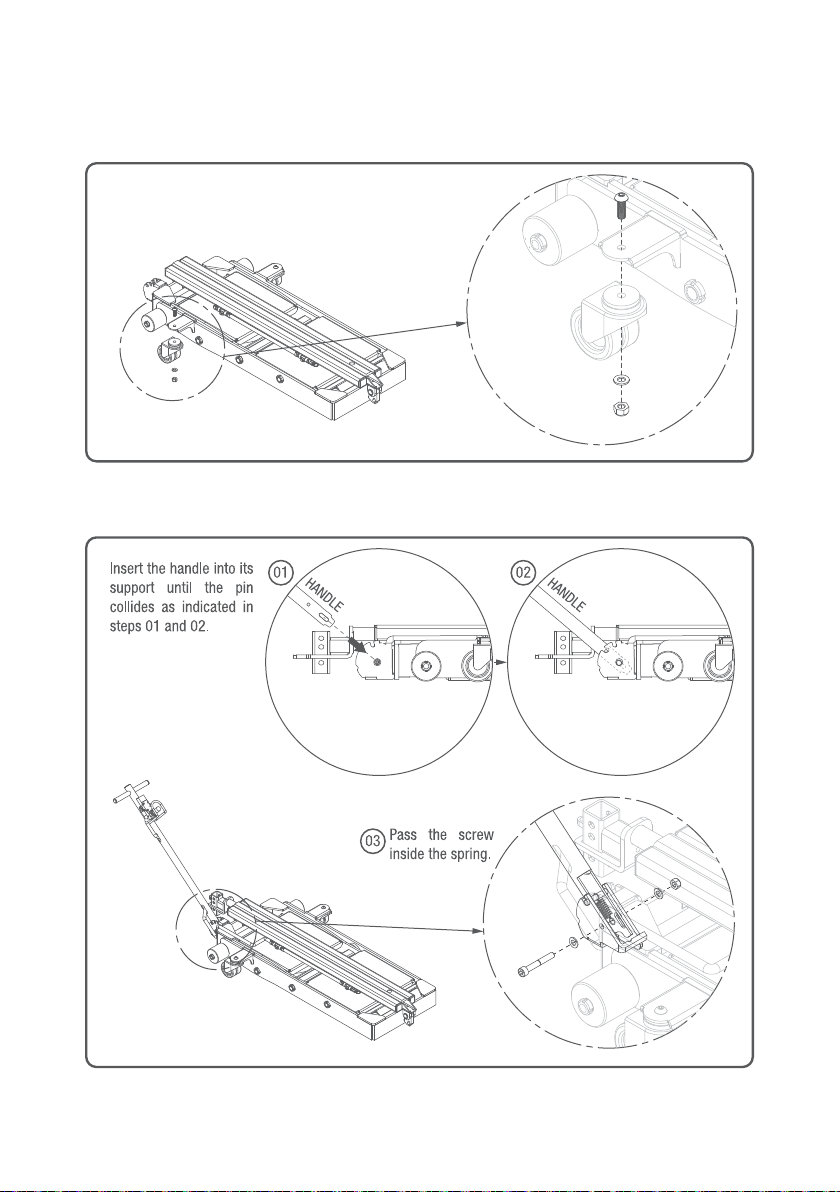
3.2 Assembly
· Set the wheels as shown in the “Figure 02”.
Figure 02
· Set the handle as shown in the “Figure 03”.
Figure 03
USER MANUAL · AE1001 MINILIFT
6
Page 7

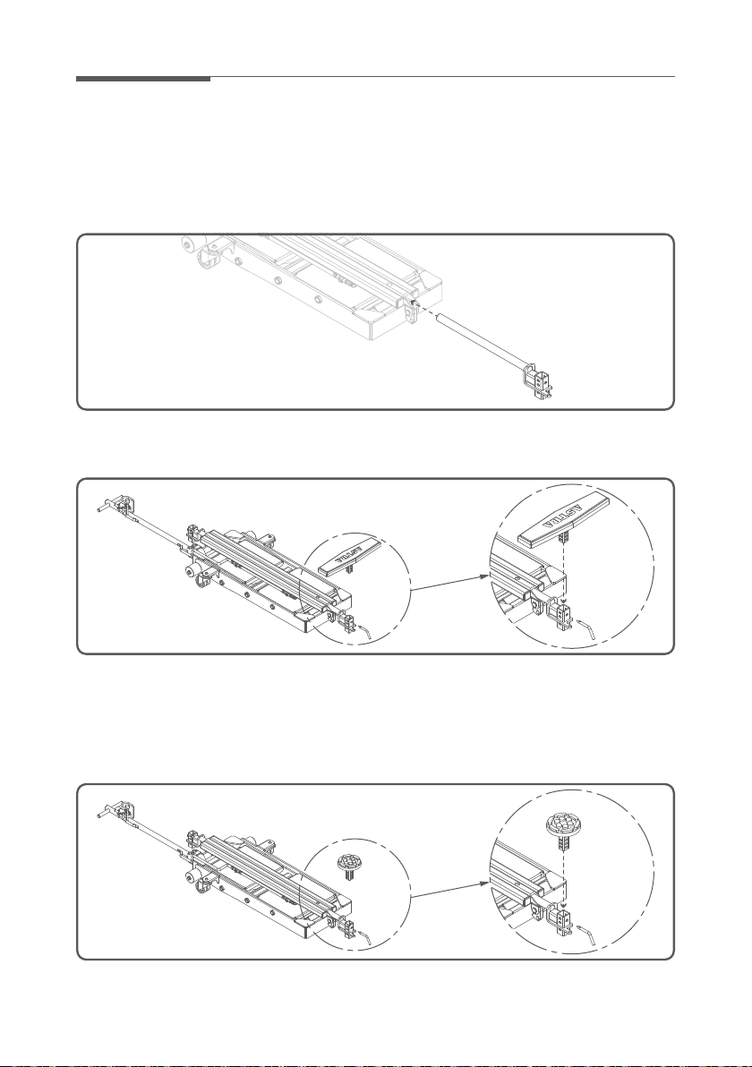
· Set the pneumatic quick connector (not supplied) as shown in the “Figure 04”.
Figure 04
3.3 Start up
· Connect the compressed air funnel and check the air pressure (from 6 to 9 BAR).
· Check that there are no leaks in the pneumatic ducts, the actuating valve and/or the pneumatic actuators.
3.4 First use
CHECKING THE LIFT / DESCENT MANEUVER
· For lifting, press the pneumatic valve lever as shown in the “Figure 05”.
· For descending, press the pneumatic valve lever as shown in the “Figure 06”.
Figure 05 Figure 06
7USER MANUAL · AE1001 MINILIFT
Page 8
4 How it works
4.1 Installation of the pads
· Place the lifting arms into the gaps of the elevator as shown in “Figure 7”.
Figure 07
· Fix the basic pads in the adaptors as showb in the “Figure 8”.
Figure 08
In those vehicles where there are no “heel pads”, but you can find some other lifting points under the
chassis, you can use the following optional pads (not included in the basic package).
· If you got these optional pads, you should follow the “Figure 09”.
Figure 09
8USER MANUAL · AE1001 MINILIFT
Page 9

4.2 Positioning of the elevator
DANGER
Use always the lift in areas with no obstructions neither inclinations.
· Drive the lift by the handle and position it under the vehicle according to the desired part to be lifted
(“Figure 10”). See sections 4.4, 4.5 and 4.6.
· Follow the steps specified in the “Figure 11” for placing the handle in horizontal position.
Figure 10 Figure 11
CAUTION
The elevator must remain perpendicular to the length of the car (“Figure 12”).
If the vehicle is new or it’s wet, you must clean the area where the pads work, to prevent
any possible slide.
Figure 12
USER MANUAL · AE1001 MINILIFT
9
Page 10

4.3 Positioning of the basic pads
Place the basic pad behind the area of the lifting point (in the middle) as shown in the “Figure 13”.
MAX
215mm
Figure 13
DANGER
Place the basic supports at the same length from the platform and without exceeding the
maximum as shown in the “Figure 14”.
MIN
123mm
Figure 14
10USER MANUAL · AE1001 MINILIFT
Page 11
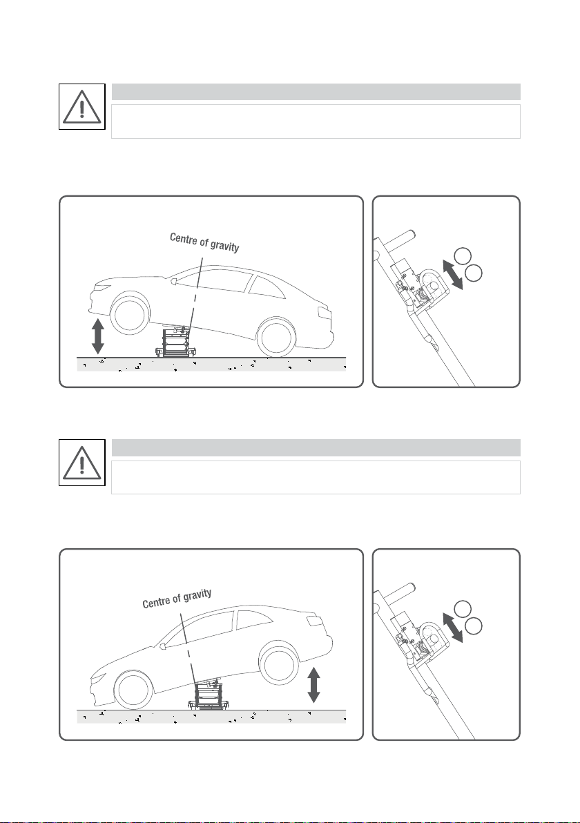
4.4 Lifting/down maneuver (front side of the vehicle)
DANGER
Never place the lift in the gravity point of the car.
Place the supplied safety stands once the vehicle has been raised.
Place the lift next to the gravity point of the car, in the front/rear part of the vehicle, as it’s showed on the
“Figure 15” and press the relevant button (“Figure 16”).
UP
01
DOWN
02
Figure 15 Figure 16
4.5 Lifting maneuver (rear side of the vehicle)
DANGER
Never place the lift in the gravity point of the car.
Place the supplied safety stands once the vehicle has been raised.
Place the lift next to the gravity point of the car, in the front/rear part of the vehicle, as it’s shown in the
“Figure 17” and press the relevant button (“Figure 16”).
UP
01
DOWN
02
Figure 17 Figure 16
USER MANUAL · AE1001 MINILIFT
11
Page 12

4.6 Special side lifting maneuver
DANGER
The side lifting maneuver is only possible when the pad is placed correctly as in “Figure 18”.
Please, be extremely caution careful during this operation.
Place the rubber pad in the hole designed for it as shown in “Figure 18”.
Figure 18
Place the lift under the vehicle. The rubber should be placed in the hole intended for it, in alignment with
the heel or tab of the vehicle as shown in “Figure 19”.
Figure 19
USER MANUAL · AE1001 MINILIFT
12
Page 13
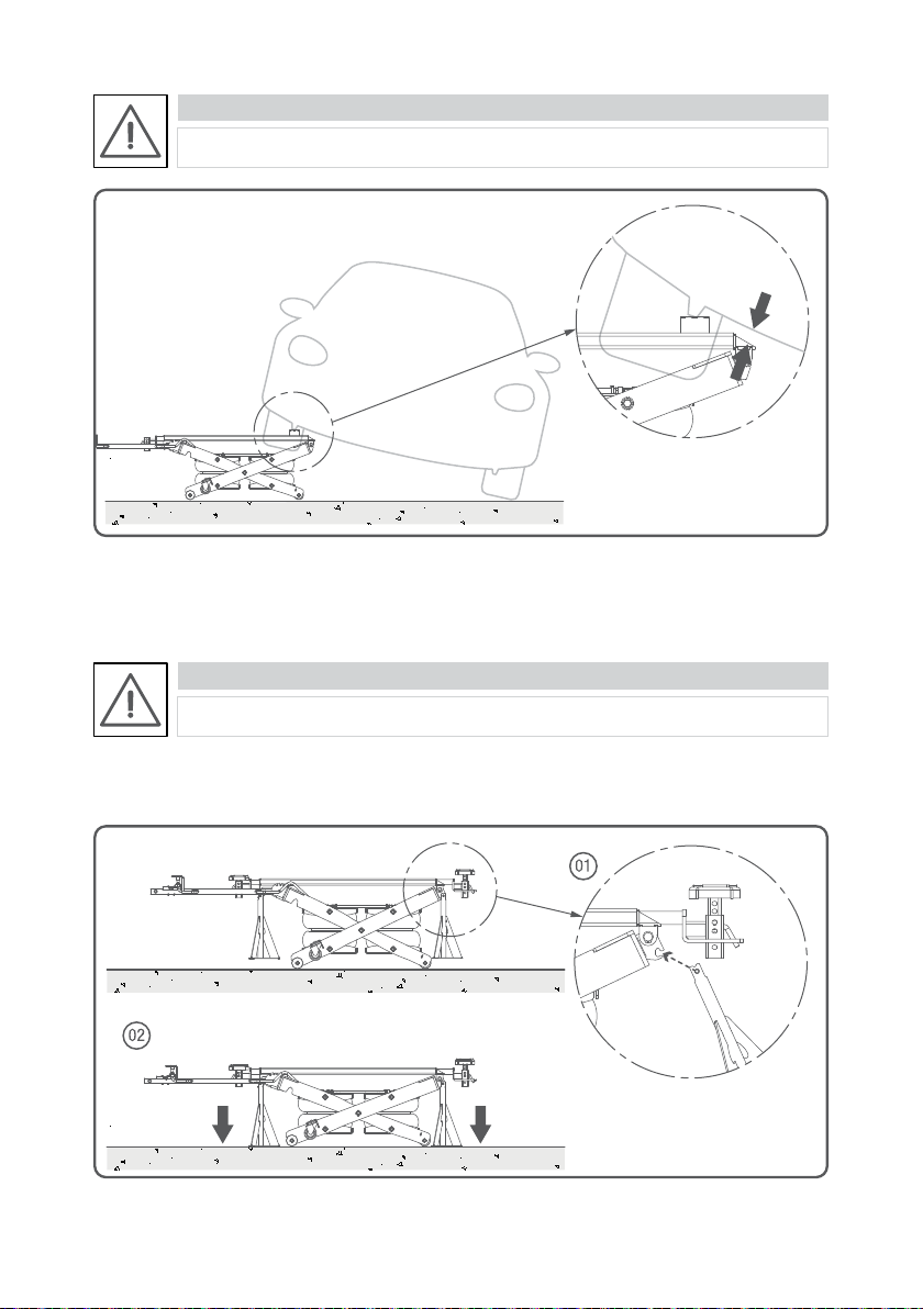
DANGER
STOP the lifting maneuver before the car be supported directly by the lift as in “Figure 20”.
Figure 20
4.7 Installation of the safety stands
DANGER
Safety stands do not allow the operator to work under the vehicle.
Place the safety stands as shown in the “Figure 21”, and descend the lift until the stands make contact
with the ground.
Figure 21
USER MANUAL · AE1001 MINILIFT
13
Page 14

4.8 Installation and use of the 4x4 adaptors (optionals)
Place the 4x4 pads as shown in “Figure 22”. It can be combined with the basic pads and the other optional
pads:
Figure 22
Figure 23
DANGER
Place the basic supports at the same length from the platform and without exceeding the
maximum length as shown in the “Figure 23”.
14USER MANUAL · AE1001 MINILIFT
Page 15

5 Maintenance
5.1 Maintenance plan
TYPE TASKSPERIOD
Before each use.
· Check the operation of the controls.
· Visual inspection of damages and leaks.
At 6 months.
At 12 months.
At 6 years.
· Cleaning (see point 5.2).
· Regular inspection (see point 5.7).
· Replacing the pneumatic ducts.
· Replacing the pneumatic actuators.
5.2 Cleaning
CAUTION
Do not use abrasive detergents or water jet directly on the lift.
Remove the dirt with a wet rag and dry it later with another rag.
15USER MANUAL · AE1001 MINILIFT
Page 16

5.7 Regular inspection
The lift must be inspected by a specialist at least once every 12 months.
NOTE
We recommend you to keep an exhaustive control of elevator inspections in the “inspection
log” that you will find on page 24 of this manual.
Here are the inspection points:
Mechanic system
· Review of all the points of union between scissors (seeger and bolts).
· Tighten all existing nuts.
· Check the welds for cracks or deformations.
· Check the readability of the adhesives.
Pneumatic system
· Review of all pneumatic ducts in search of leaks, cracks, deformations or any deterioration
symbol.
6 Technical description
6.1 Technical data
Maximum load admitted
Maximum height from the ground
Minimum height from the ground
Maximum width
Minimum length
Long maximum
Weight of the structure with accessories
Pneumatic circuit pressure
Ascent time
Descent time
6.2 Schematic Pneumatic Circuit
Figure 24
2500 Kg
550 mm
130 mm
626 mm
1382 mm
2060 mm
152 Kg
6 a 8 BAR
13 seconds
17 seconds
16USER MANUAL · AE1001 MINILIFT
Page 17

6.3 Exploded view
INDEX
Top (Page 18)
Pneumatic system (Page 19)
Scissors (Page 20)
Figure 25
17USER MANUAL · AE1001 MINILIFT
Page 18
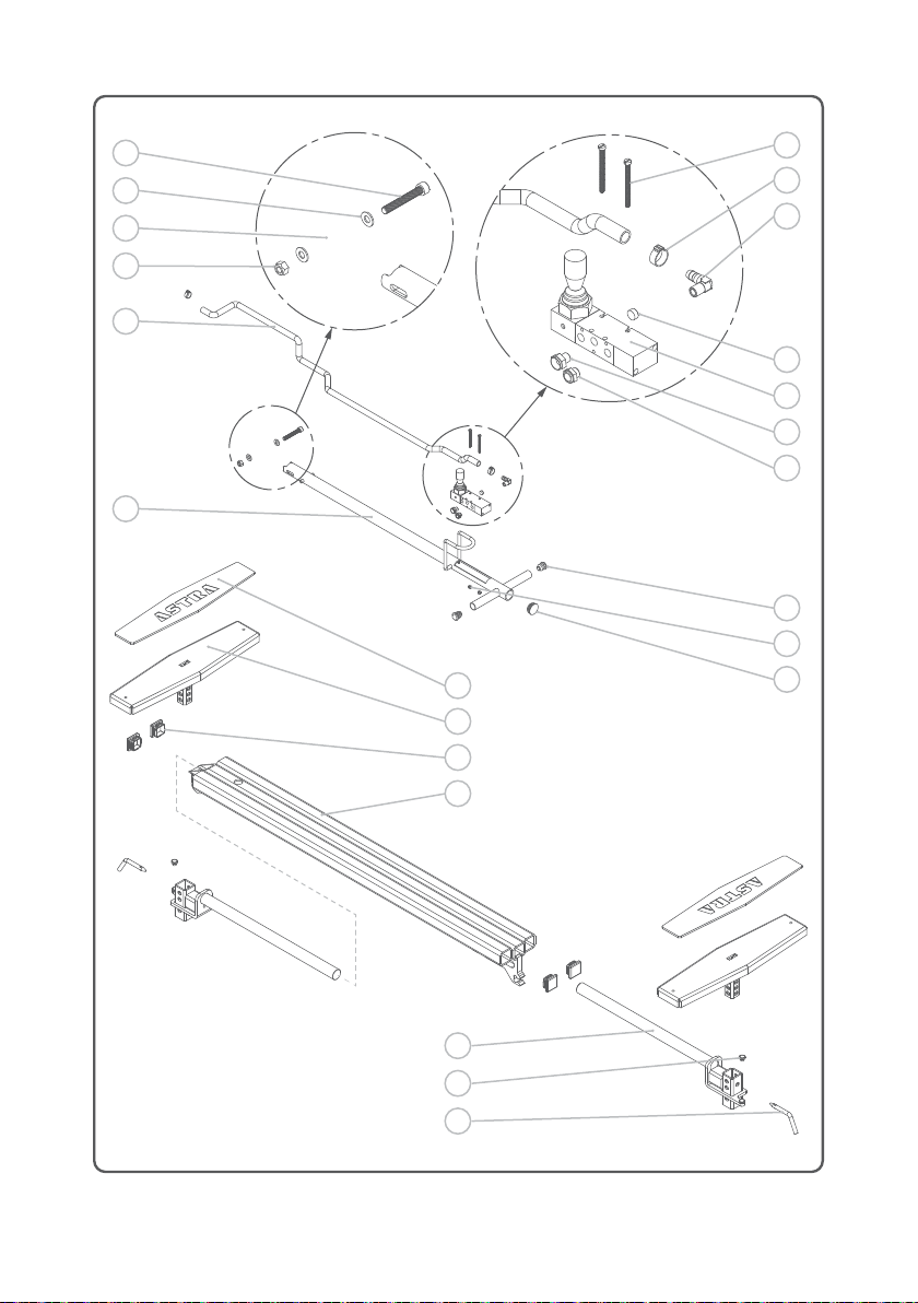
01
02
03
04
05
06
17
18
19
20
07
08
09
10
11
12
13
14
15
16
Figure 26
21
22
23
18USER MANUAL · AE1001 MINILIFT
Page 19

24
25
26
27
28
29
30
31
30
29
Figure 27
19USER MANUAL · AE1001 MINILIFT
Page 20

32
33
34
35
36
37
38
39
40
41
42
43
44
45
46
47
48
Figure 28
49
50
51
20USER MANUAL · AE1001 MINILIFT
Page 21

Number
01
02
03
04
05
06
07
08
09
10
11
12
13
14
15
16
17
18
19
20
21
22
23
24
25
26
27
28
29
30
31
32
33
34
35
Description Quantity Code
SCREW DIN912 8.8 M8X55
WASHER DIN125 M8
SPRING
NUT DIN985 M8
HOSE
HANDLE
SCREW DIN84 M4x50
1-EAR CLAMP
ELBOW CONECTOR FOR TUBE
PLUG DIN906 1/8M ZN
PNEUMATIC MANUAL VALVE
REDUCTION NUT M-F 3/1-1/4
COMPACT SILENCER MALE THREAD 1/8
PLUG
NUT DIN985 M4
PLUG
RUBBER PADS
PADS
PLUG
PLATTFORM FOR PADS
TELESCOPIC ARM
MAGNET M4
ERGONOMIC FASTENER
SECUTITY VALVE 8BAR
“T” FITTING 1/4
PARALLEL MALE HOSE ADAPTOR 1/4 D9
HOSE
SCREW DIN7991 M8
EXT. TRAY
INT. TRAY
AIR SPRING
NYLON WHEEL
FLANGED BUSHING
BOLT
GUK 20X1
01
02
01
04
01
01
02
04
01
01
01
01
01
02
02
01
02
02
04
01
02
02
02
01
02
03
01
08
02
02
02
04
10
08
10
MPTO00132
MPTO00074
MLA141P03
MPTO00044
MLA140P01
MLA140
MPTO00128
MPTO00082
MPTO00078
MPTO00077
PCSN00007
MPTO00102
PSCN00005
MPMP00001
MPTO00129
MPMP00018
MLA160P01
MLA161
MPMP00005
MLA130
MLA151
MPTO00010
SP0000P02
PSCN00008
MPME00036
MPTO00075
MPMP00003
MPTO00021
MLA100P01
MLA100P02
PSCN00001
SP0000P01
MPTO00063
MLA100P05
MPTO00054
USER MANUAL · AE1001 MINILIFT
21
Page 22

Number
36
37
38
39
40
41
42
43
44
45
46
47
48
49
Description Quantity Code
AXIS
INT. SCISSORS
GUK 15X1
SEEGER DIN471 D10
HANDLE SUPPORT
SCREW DIN7380 M8
FASTENER
EXT. SCISSORS
SEPARATING
BOLT
SCREW DIN7380 M10
ROTATING WHEEL
WASHER DIN125 M10
NUT DIN985 M10
01
01
04
04
01
02
02
01
02
02
02
02
02
02
MLA100P06
MLA120
MPTO00053
MPTO00120
MLA170
MPTO00010
MLA100P04
MLA110
MLA100P08
MLA100P03
MPTO00006
MPME00015
MPTO00028
MPTO00041
22USER MANUAL · AE1001 MINILIFT
Page 23

6.4
Spray booths · Welding · Benches · Lifts
DECLARATION OF CONFORMITY
(as established by the Directive 2006/42/CE)
The company: APUANA, S.L. (workshop equipment manufacturer)
C/ Cabrera 6
08192 SANT QUIRZE DEL VALLÈS (Barcelona)
ID N.: B-60415114
The legal representative declares, under his sole responsibility, that the mobile lift:
MODEL: AE1001
SERIAL NUMBER: ______________
Conforms with the Directives of the Parliament and the European Council:
· 2006/42/CE concerning the application of the laws of the member states on
machines.
It adapts to the standard (s) or policy (s) of the document (s) of:
· UNE-EN 1494, Mobile or portable jacks and associated lifting equipment,
and has been applied in harmony with the following standards:
· EN 292. General principles for design.
· EN 626-1, Reduce risks to human health.
Responsibilities for parts or components added by the customer are excluded.
Marius Virgil, responsible for the technical record.
Barcelona on January 09, 2019
Stamp and signature
D
A
E
M
I
N
&
D
E
N
G
I
S
S
P
A
I
E
N
D
A
R
T
A
S
Nicola Ballero
Managing Director
23USER MANUAL · AE1001 MINILIFT
Page 24

7 Inspection log
Date Maintenance plan Result Signature
24USER MANUAL · AE1001 MINILIFT
Page 25

Date Maintenance plan Result Signature
USER MANUAL · AE1001 MINILIFT
25
Page 26

Date Maintenance plan Result Date
USER MANUAL · AE1001 MINILIFT
26
Page 27

Page 28

Spray booths · Welding · Benches · Lifts
2018 · astraballero.com
 Loading...