

Page 1

USE AND MAINTENANCE
Euro 3
GB
HANDBOOK
Page 2

Page 3
USE AND MAINTENANCE
Euro 3
GB
HANDBOOK
Page 4

The company ASTRA VE I COLI INDUSTRIAL I reserves the righttomakeany modifications to vehicles for technical or commercial reasons at any time; the in f orm a tion , description s and illustrations contained in this publication are therefore correct at the time going to
press.
This Use and Maintenance Handbook deals with optional equipme nt which cannot be present on your vehicle, and alternative equipment
as well (e.g. mechanical and automatic gearbox).
Moreover, the regulations in force in certain countries affect the standard equipment of the vehicle.
This publication could therefore contain information and illustrations not corresponding to the vehicle version provided on a particular market.
ASTRA Veicoli Industriali
Product Logistics
Via Caorsana, 79 --- 29100 PIACENZA (Italy)
Tel. 0523/5431 --- Fax 0523/543459
Print cat. A3502196
First edition - DECEMBER 2011
Second edition - FEBRUARY 2012
Prepared by SIPAL S.p.A. --- Torino (Italy)
Reproduction, whether total or partial, of the text and illustrations is strictly forbidden.
Page 5

HD9 Euro3
I
Introduction VII....................................
After sales service VIII..............................
Warning IX........................................
TECHNICAL DATA 1-1.........................
Position of vehicle identification data plates 1-3.........
Model identification plate 1-3.........................
Imprinting of the vehicle chassis 1-3..................
Vehicle identification plate 1-3........................
Chassis punching 1-4...............................
Vehicle registration number 1-4.......................
Vehicle identification plate 1-5........................
Engine 1-6........................................
Main specifications 1-6..............................
Manual transmission 1-9............................
Clutch 1-9.........................................
Gear shift 1-9......................................
Ratios 1-9.........................................
T ransfer distributor 1-10............................
Axles 1-11.......................................
Front steering axle 1-11............................
Front steering drive axle 9 ton 1-11...................
Front steering drive axle 10 ton 1-11..................
Single rear drive axle 1-12..........................
Tandem rear drive axles 1-12........................
Brakes (simplex without ABS) 1-13...................
Brakes (duplex with ABS) 1-14......................
ABS 1-14........................................
Tyr e s 1 - 1 5........................................
Suspension 1-16..................................
Steering 1-17.....................................
Vehicles without auxiliary cylinder 1-17...............
Vehicles with auxiliary cylinder 1-17..................
Electrical system 1-18..............................
Chassis 1-19.....................................
Standard fuel tank 1-19............................
Oversize fuel tank 1-19.............................
Tightening torques 1-20............................
Vehicle outfitting 1-22..............................
Keys 1-22........................................
INSTRUCTIONS FOR USE 1-23..............
General instructions for correct use of the vehicle 1-25..
Rangeofuseoftheengine 1-28.....................
Left hand drive vehicles 1-29........................
Cab-external 1-29.................................
External lighting 1-30..............................
Front lights 1-30..................................
Rear lights 1-31...................................
Doors 1-32.......................................
Central locking remote control 1-34..................
Replacing remote control battery 1-35................
Driver’s seat 1-36.................................
Internal lighting device 1-38.........................
Upper dashboard 1-38.............................
External rear view mirrors 1-39......................
Mirror selection and handling 1-40...................
Seats 1-42.......................................
Fore and aft adjustment 1-42........................
Cushion angle adjustment 1-42.....................
Seat suspension adjustment 1-42....................
Springing system adjustment 1-43...................
Height adjustment 1-43............................
Backrest angle adjustment 1-43.....................
Seat belts 1-44...................................
Electric window control 1-46........................
Electric window risers control 1-46...................
Hatch 1-47.......................................
Compartments 1-48...............................
Dashboard 1-48..................................
Upper dashboard 1-48.............................
Door 1-49........................................
Page 6

II
HD9 Euro3
Tunnel 1-49......................................
Seat 1-49........................................
Rear wall 1-49....................................
Accessories - devices 1-50.........................
Sun blind tabs 1-50................................
Grip handle 1-50..................................
Coat hook 1-50...................................
Cigar lighter 1-50..................................
Ashtray 1-50......................................
12Volt current socket 1-50..........................
Controls 1-51....................................
Controls on dashboard 1-51........................
Module holder dashboard controls 1-52..............
Steering wheel position control 1-53..................
Accelerator 1-54..................................
Service brake 1-54................................
Clutch 1-54.......................................
Manual transmission control 1-55....................
All vehicles 1-56..................................
Instruments 1-56..................................
Instrument panel 1-56..............................
Functions of instrument panel keys 1-58..............
Warning lights panel A details 1-59...................
Warning lights panel B details 1-60...................
Warning lights panel C details 1-61..................
Warning lights on dashboard 1-62...................
Control operation 1-64.............................
Position and headlight controls 1-64..................
Headlight control 1-64.............................
Direction indicator control 1-65......................
Horn 1-65........................................
Windscreen washer/wiper control 1-66...............
Ignition switch 1-67................................
Engine braking control - Vehicles without
intarder 1-67.....................................
Engine braking control - Vehicles with intarder 1-67.....
Cruise control 1-68................................
Hazard light control 1-69...........................
Exhaust brake pre-selection 1-69....................
Courtesy light switch 1-70..........................
Electro-pneumatic horn pre-selection 1-70............
Swivelling light control 1-71.........................
Work light 1-71...................................
Rear fog light 1-71.................................
Fog light control 1-72..............................
Electric battery isolator control 1-72..................
ASR off command 1-73............................
ABS off command 1-74............................
Distributor-reducer (transfer) 1-75....................
Differential lock control (2 axle vehicles) 1-76..........
Reat longitudinal distributor and transverse
differential lock (4x4 vehicles only) 1-76...............
Rear transverse differential lock
(4x2 vehicles only) 1-76............................
Differential lock control (3-4 axle vehicles) 1-77........
Interaxle longitudinal differential lock and rear
transverse differential lock 1-77......................
Longitudinal distributor differenital lock
(6x6, 8x6 and 8x8 vehicles only) 1-77.................
Power take off control 1-80.........................
Multipower PTO on flywheel 1-81....................
P.T.O. manual transmission 1-82.....................
Tachometric simulator 1-83.........................
Heating and ventilation 1-85........................
Climate control system air vents 1-85.................
Climate controls 1-86..............................
Most common control position 1-88..................
Auxiliary heater (WEBASTO) 1-92....................
Auxiliary heater control panel 1-93...................
Operation of the heater with key-off without
programming 1-95................................
Page 7

HD9 Euro3
III
Operation of the heater with key-on without
programming 1-96................................
Use of the vehicle 1-97.............................
Precautions for the initial period of use 1-97...........
General checks 1-97...............................
Refuelling 1-98...................................
Starting engine 1-99...............................
Checks before starting 1-99.........................
Starting from the driver’s cabin 1-100.................
Starting from engine bay 1-101......................
Tow starting 1-101.................................
Emergency electrical power 1-102...................
Cold start 1-104...................................
Starting with heater 1-105..........................
Stopping engine 1-106.............................
Stopping from drivers cabin 1-106...................
Stopping from engine bay 1-106.....................
Manual transmission vehicles 1-109..................
Starting the vehicle 1-109...........................
Driving the vehicle 1-110...........................
Gearbox 1-112....................................
Gearbox control 1-112.............................
Operating the clutch 1-113..........................
Splitter control 1-114...............................
Stopping the vehicle 1-115.........................
All vehicles 1-117.................................
Speed programmer 1-117..........................
Engine idle speed adjustment / memorising 1-117.....
Vehicle speed (cruise control) adjustment /
memorising 1-119.................................
Enable 1-121.....................................
Changing setting 1-122............................
Tip Function 1-122................................
Ramp Function 1-122..............................
Permanent disable 1-123...........................
Temporary disable 1-123...........................
Engine brake control selection
(vehicles without intarder) 1-124.....................
Engine brake and intarder control selection
(vehicles fitted with intarder) 1-126...................
Vehicle parking 1-129..............................
Parking brake 1-130...............................
Parking brake - vehicles without trailer 1-130..........
Parking brake - vehicle with trailer 1-131..............
Parking brake efficiency check 1-131.................
Additional parking brake 1-132......................
A.B.S. Anti-lock braking system 1-133................
Semi-trailer coupling 1-134.........................
Coupling 1-134...................................
Check closure 1-135...............................
Uncoupling 1-135.................................
ABS coupling (if foreseen) 1-135....................
Pivoting fifth wheel 1-136
Trailer hooking - I type 1-137........................
Trailer hooking - II type 1-138.......................
Norms for towing trailer / semi-trailer 1-139............
T railer coupling 1-140..............................
Semi-trailer coupling 1-140.........................
Ladder 1-140.....................................
Towing the vehicle 1-141...........................
Wheel change 1-146...............................
Diagnostics - Vehicle 1-151.........................
Quick guide to the most common problem 1-151......
Quick guide to most common problems - Vehicles
steering system with steering emergency circuit
without auxiliary cylinder 1-151......................
Quick guide to most common problems - Vehicles
steering system with steering emergency circuit
with auxiliary cylinder 1-152.........................
Diagnostics - Control systems 1-153.................
...........................
Page 8

IV
HD9 Euro3
MAINTENANCE INSTRUCTIONS 1-155......
Introduction 1-157.................................
Opening radiator grill 1-158.........................
Tilting the cab 1-159...............................
Lifting the cab 1-159...............................
Lowering the cab 1-160............................
Main levels check 1-162............................
Check engine oil level 1-162........................
Check engine coolant level 1-163....................
Check windshield washer level 1-163.................
Engine 1-164.....................................
Changing engine oil 1-164..........................
Replacing engine oil filter F2B 1-166.................
Replacing engine oil filter F3B 1-167.................
Engine oil vapour filter change 1-168.................
Accessory drive belts check 1-169...................
Intake-exhaust valve play adjustment 1-170...........
Injector-pump pre-load adjustment 1-170.............
VGT actuator grease application procedure 1-170......
Fuel feed system 1-171............................
Bleed fuel tank condensation water 1-171.............
Fuel tank water drain 1-172.........................
Purging water from fuel decanter 1-172...............
Replacing fuel filters 1-173..........................
Replacing fuel decanter filter 1-174...................
Fuel circuit bleeding 1-175..........................
Intake system 1-176...............................
Intake system seal check 1-176.....................
Turbocompressor lubrication check 1-176.............
Intercooler external cleaning 1-176...................
Main filter element cleaning/change 1-177............
Safety secondary filter element replacement 1-178.....
Replacing the VGT piloting hoses filtering
element 1-179....................................
Cooling system 1-180..............................
Replacing engine coolant 1-181.....................
Checking antifreeze concentration 1-182..............
Clutch 1-183......................................
Check clutch disengagement 1-183..................
Oil level check 1-183...............................
Changing the hydraulic fluid 1-184...................
Air bleeding 1-184.................................
Multipower PTO 1-185.............................
Oil level check 1-185...............................
Oil change 1-186..................................
ZF NMV 221 power take off 1-187....................
Oil level check/change 1-187........................
Oil filter change 1-187..............................
Gearbox 1-188....................................
Oil level check 1-188...............................
Oil change 1-189..................................
Distributor-transfer (transfer) - type I 1-190............
Oil level check 1-190...............................
Oil change 1-191..................................
Distributor-transfer (transfer) - type II 1-192............
Checking oil level 1-192............................
Changing oil 1-193................................
Transmission shafts 1-194..........................
Greasing 1-194...................................
Axles 1-195......................................
Front axle 1-195...................................
Check differential oil level 1-195.....................
Differential oil change 1-195........................
Hub oil level check 1-196...........................
Hub oil change 1-197..............................
Front axle - 10 ton version / K version 1-198...........
Checking differential oil level 1-198...................
Changing differential oil 1-198.......................
Checking oil hub level 1-199........................
Changing hub oil 1-200............................
Front intermediate axle 1-201.......................
Check differential oil level 1-201.....................
Page 9

HD9 Euro3
V
Differential oil change 1-201........................
Hub oil level check/change 1-201....................
Rear intermediate axle 1-202........................
Oil level check 1-202...............................
Changing oil 1-203................................
Rear axle 1-204...................................
Oil level check 1-204...............................
Changing oil 1-205................................
Suspensions 1-206................................
Leaf spring pins greasing 1-206.....................
Carriage pin greasing on 3 and 4-axle vehicles 1-207...
Steering system 1-208.............................
Oil level check 1-208...............................
Changing the hydraulic oil - Vehicles without
auxiliary cylinder 1-209.............................
Dumping 1-209...................................
Filling 1-209......................................
Bleeding off air 1-210..............................
Changing the hydraulic oil for - Vehicles with
auxiliary cylinder 1-211.............................
Dumping 1-211...................................
Filling 1-211......................................
Bleeding off air 1-212..............................
Replacing oil filter 1-213............................
Stub axle greasing 1-214...........................
Steering linkage grease application 1-215.............
Front wheel toe-in check 1-216......................
Front wheel toe-in check 1-217......................
Compressed air system 1-218.......................
Tank visual inspection 1-218........................
Air drier functionality check 1-219....................
Air dryer filter change 1-220.........................
Braking system 1-221..............................
Shoe-drum play check 1-221.......................
Check pedal distributors 1-221......................
Tyres and wheels 1-222............................
Checking wheels and tyres 1-222....................
Inflating tyres 1-222................................
Cab tipping system 1-223..........................
Oil level check / fluid change 1-223..................
Greasing 1-224...................................
Towing systems 1-225.............................
Greasing the fifth wheel 1-225.......................
Tow hook greasing - Type I 1-226....................
Tow hook greasing - Type II 1-226...................
Air conditioner 1-227...............................
Air-conditioner system maintenance 1-227............
System charge check 1-228........................
Supplementary heater 1-229........................
Replacing the supplementary heater fuel filter 1-229....
Bodywork 1-230..................................
Replacing front windscreen wiper blade 1-230.........
Windscreen washer reservoir 1-230..................
Bodywork maintenance 1-231.......................
Cleaning plastic parts 1-231........................
Cleaning seat belts 1-231...........................
Lighting system 1-232.............................
Headlight/front sidelight bulb replacement 1-232.......
Headlight alignment 1-233..........................
Front direction indicator light bulb replacement 1-234...
Side direction indicator bulb replacement 1-234........
Rear light bulb replacement 1-235...................
Front clearance light bulb replacement 1-236..........
Rotary warning light bulb replacement 1-236..........
Ceiling light bulb replacement 1-236.................
Replacing cab step light 1-236......................
List of bulbs 1-237.................................
Electrical system 1-238.............................
Precautions 1-238.................................
Battery maintenance (unsealed batteries) 1-239........
Recharge with external devices 1-241................
Changing the battery 1-242.........................
Page 10

VI
Interconnection control unit (fuses and relays) 1-243....
Fuse replacement 1-243............................
Fuse / relays holder plate 1-244.....................
Fuses 1-245......................................
Fuse holder (70005) 1-245..........................
Fuse holder (70601) 1-246..........................
Fuse holder (70602) 1-246..........................
Fuse holder (70401) 1-246..........................
Fuse holder (70402) 1-247..........................
Fuse holder (70403) 1-247..........................
Fuse holder (70403) not used 1-247..................
Relays 1-248.....................................
Supplementary relays 1-249........................
Additional relays board 1-250.......................
Supplementary flying fuse 1-251.....................
TABLE AND DIAGRAMS 1-253................
Introduction 1-255.................................
Lubricants, oils, hydraulic fluids and filter refilling/
replacement diagram 1-256.........................
2 axle vehicles 1-256...............................
3 axle vehicles 1-258...............................
4 axle vehicles 1-260...............................
Location of components 1-262......................
Engine F3B 1-262.................................
Engine F2B 1-264.................................
Manual transmission 1-266.........................
Multipower/NMV 221 power take off 1-268............
Drive line 1-270...................................
Greasing transmission shaft 1-272...................
Suspension geasing 1-274.........................
Steering linkages, semi-trailer fifth wheel, tow
hook greasing 1-276...............................
Systems 1-278....................................
Service schedule 1-280............................
Lubricant and hydraulic fluid tables 1-284.............
HD9 Euro3
Page 11
HD9 Euro3
INTRODUCTION
This Use and Maintenance Handbook is divided into 4 parts, each of which systematically
subdivided according to subject, for quick and easy consulting.
1) Technical specifications: this contains all the characteristic data which should be read
through at least once to acquire a working knowledge of the vehicle.
2) Use of the vehicle and practical hints: this contains information relevant to the main controls and instruments, and the main rules to be followed especially for new vehicles.
3) Maintenance instructions: this section contains the functional instructions for checking
and maintaining the vehicle which must be implemented to ensure satisfying operation,
cost-effective running and long life of the vehicle.
4) Tables and diagrams: contains vehicle scheduled maintenance tables and diagrams.
In this Use and Maintenance Handbook there are texts that are highlighted in a particular
manner:
VII
Failure to heed and/or correctly carry out
procedures, technical information and
precautions given may cause injury.
Failure to heed and/or correctly carry out
procedures, technical information and
precautions given may cause damage to
the vehicle.
Procedures, technical information and
precautions which must be highlighted.
Failure to heed and/or correctly carry out
procedures, technical information and
precautions given may cause environmental damages.
Page 12

VIII
AFTER SALES SERVICE
Warranty
To comply to the warranty conditions, all the instructions for correct use and maintenance
described in this manual are to be followed.
After-sales service
For any type of servicing the ASTRA V.I. Dealership is at the complete disposal of the Customer. Equipment and skilled staff are available for maintenance or repair jobs. The ASTRA
V.I. Dealership is always willing to offer you hints and advice to ensure you get best performance from your vehicle.
Spare parts
Any spare parts used for replacements are to be “GENUINE ASTRA SPARES” which can be
obtained from the dealer warehouses and authorised workshops. Remember that a correct
order for spare parts must always include the following details:
--- t y p e o f v e h i c l e ;
--- c h a s s i s n u m b e r ;
--- reference and category numbers, to be found in the Spare Parts Catalogue.
If the items are parts of a main group (engine, cab, axles, power steering, gearbox etc.) indicate also the group version and serial number.
HD9 Euro3
Page 13

HD9 Euro3
WARNING
Assembly of accessories, additions and modifications on the vehicle are to be carried out in
conformity with ASTRA directives. The specific document “Directive for conversion and outfittings” can be obtained as a guideline from the After Sales Service workshops.
It is reminded that, especially regarding the electrical system. there are several electrical
sockets available (standard or optionals) to simplify electrical operations carried out by the
outfitters.
For any exemption from the directives for the conversion it is necessary to have authorisation
from ASTRA.
It is strictly forbidden to make modifications or connections to the wiring of electronic control
units. In particular the interconnection lines between control units (CAN lines) are never to
be interfered with.
Diagnostics and maintenance operations are to be carried out by skilled personnel using
approved diagnostics equipment.
Ignoring these afore-mentioned prescriptions will annul the contractual warranty .
IX
The handbook contains use and maintenance instructions for all systems foreseen
on the vehicle by the Manufacturer.
Some systems described in the handbook may not be present on Your vehicle,
according to the chosen version and
market the vehicle is destined for.
Page 14

X
HD9 Euro3
Page left intentionally blank
Page 15

HD9 Euro3
1-1
Technical data
Page 16

1-2
HD9 Euro3
Page left intentionally blank
Page 17

HD9 Euro3
342BNU001L
POSITION OF VEHICLE IDENTIFICATION
1
DATA PLATES
Model identification plate
Located on the side walls of the cab (Fig. 1,
see arrow).
Imprinting of the vehicle chassis
Punch marked at the front end of the righthand side member (Fig. 2, see arrow).
(see following page).
Vehicle identification plate
On bonnet left side in cabin for vehicle identi-
2
fication as per EU standards (Fig. 3, see arrow).
3
1-3
272CDT001
Page 18
1-4
HD9 Euro3
b
1
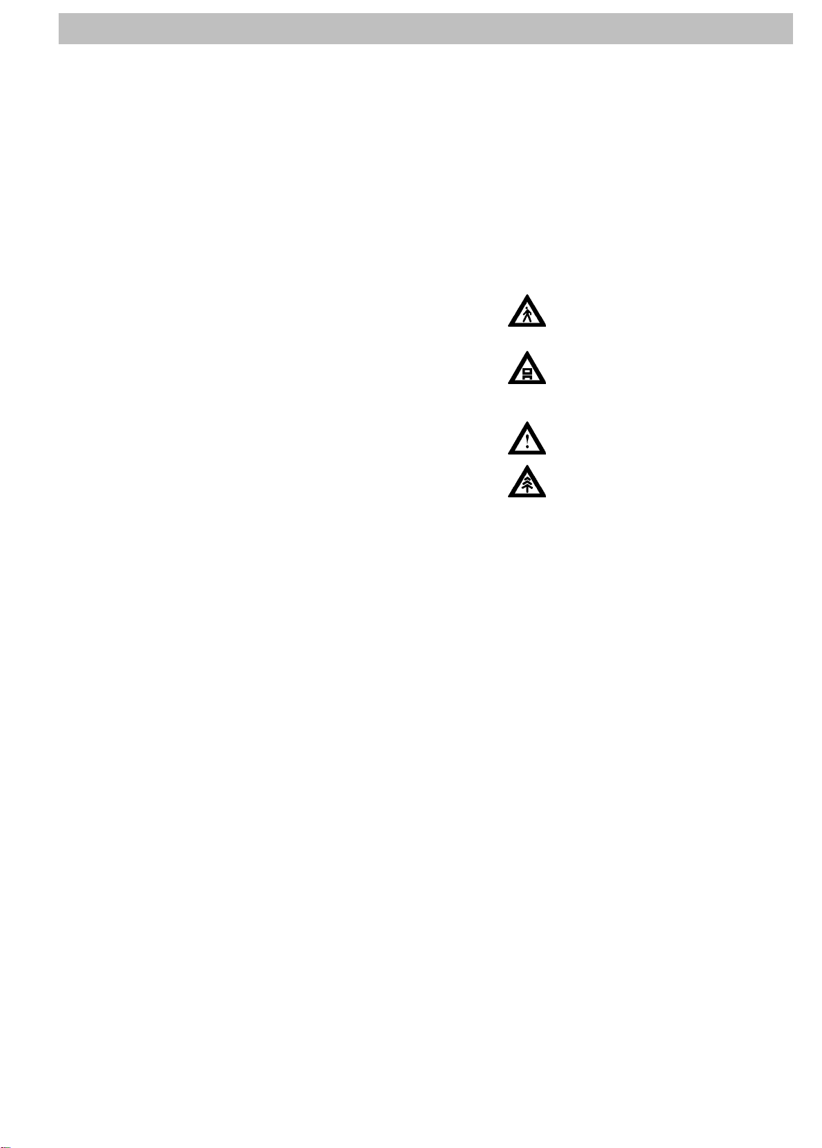
Chassis punching (Fig. 1)
a. right side member
b. rear axle front leaf spring
a
2
Vehicle registration number (Fig. 2)
1) World–wide identification of manufacturers (Astra Veicoli Industriali S.p.A.)
2) Type of vehicle
3) Vehicle features
4) Year of construction
5) Production facility (P=Piacenza)
6) Chassis number
Page 19
HD9 Euro3
1-5
1
3
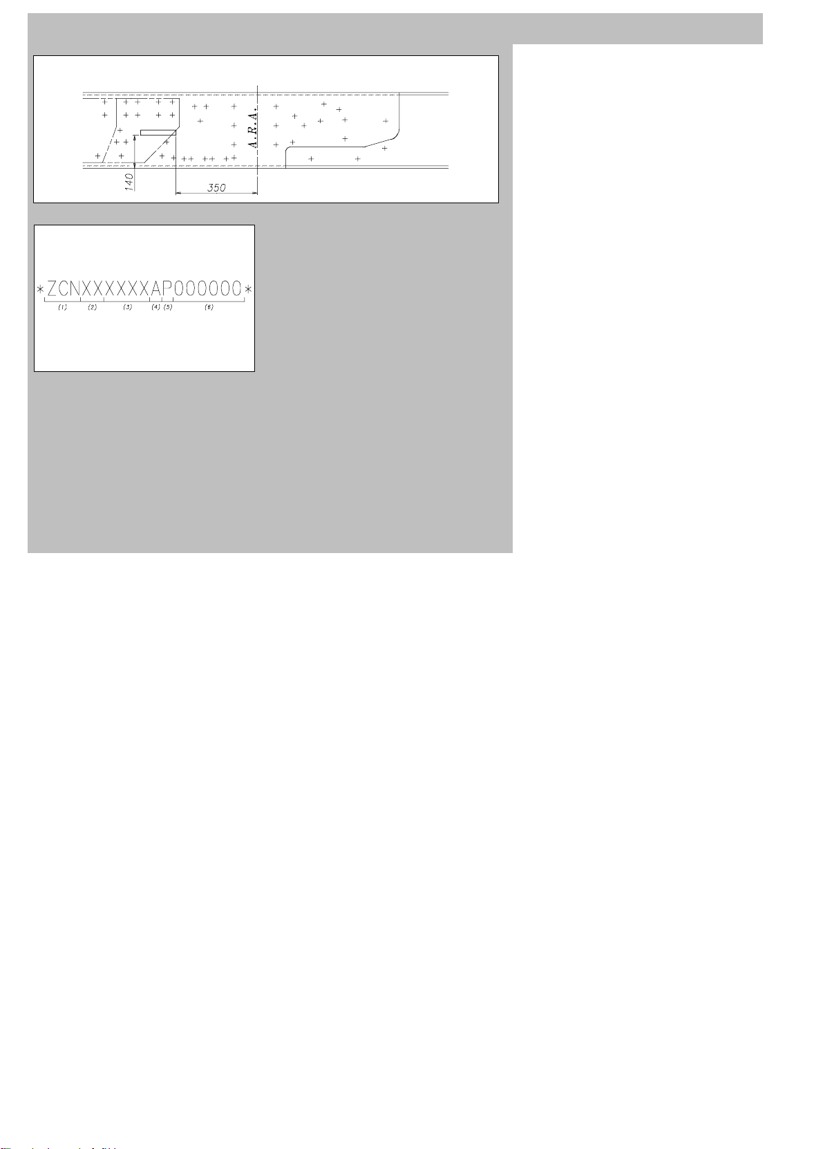
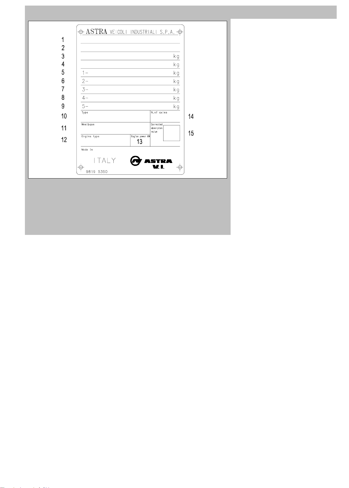
Vehicle identification plate (Fig. 3)
1) Type approval number markings
2) Vehicle chassis punch markings
3) Overall vehicle weight
4) Overall tractor + trailer/semitrailer
weight
5) Maximum admissible weight 1st axle
6) Maximum admissible weight 2nd axle
7) Maximum admissible weight 3rd axle
8) Maximum admissible weight 4th axle
9) Maximum admissible weight on fifth
wheel (tractor versions only)
10) Vehicle commercial denomination
11) Axle spacing
12) Engine type
13) Engine power
14) Number of axles
15) Grade of smoke
Page 20
1-6
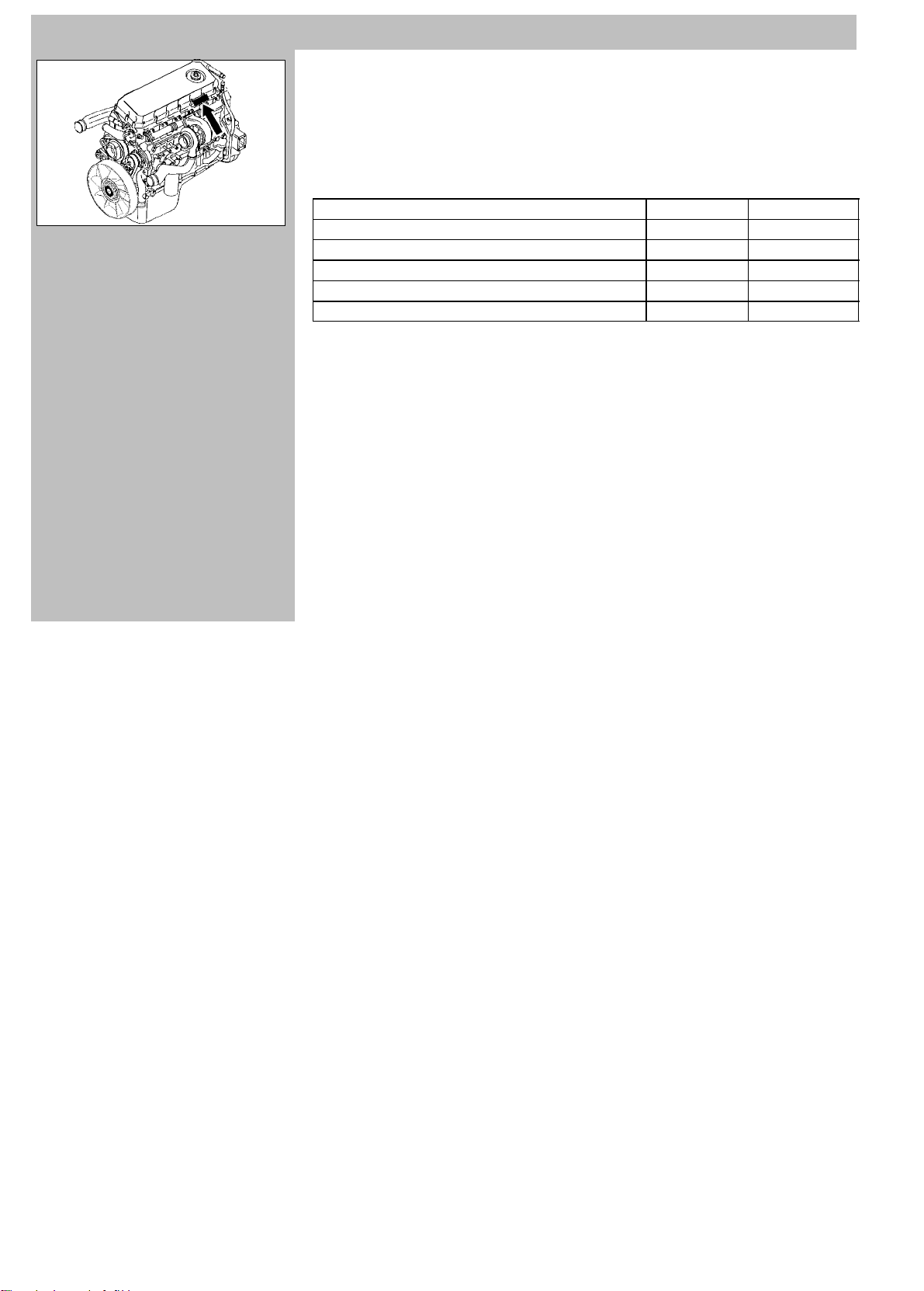
ENGINE
1
Engine
IVECO F2B (Cursor 8) (Fig. 1)
4-stroke Diesel, liquid cooled, variable geometry exhaust gas turbocharger.
Main specifications
HD9 Euro3
285ADT002L
Number of cylinders
6
Bore mm 115
Stroke mm 125
Total displacement cm
3
7790
Compression ratio 16.5
Injection order 1-4-2-6-3-5
Page 21
HD9 Euro3
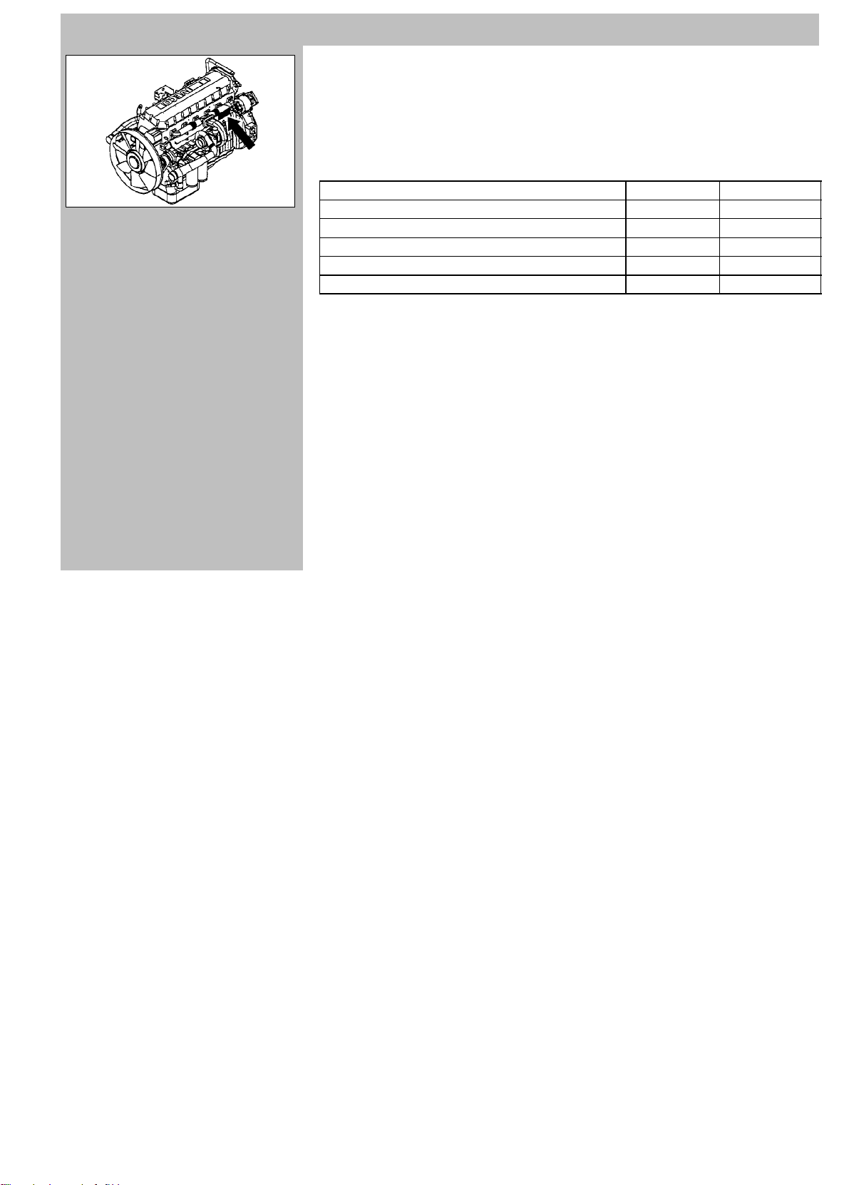
ENGINE
1
Engine
IVECO F3B WG (Cursor 13) (Fig. 1)
4-stroke Diesel, liquid cooled, turbocharger
with Wastegate pressure limiter.
Main specifications
1-7
285ADT003L
Number of cylinders
6
Bore mm 135
Stroke mm 150
Total displacement cm
3
12882
Compression ratio 16.5
Injection order 1-4-2-6-3-5
Page 22
1-8
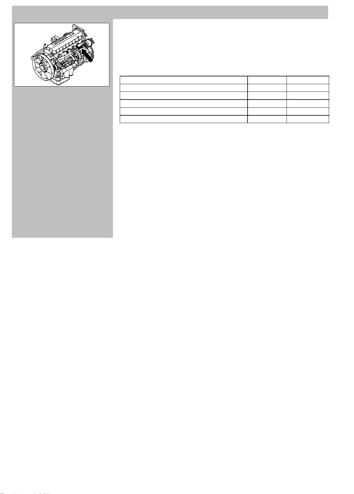
ENGINE
1
Engine
IVECO F3B VGT (Cursor 13) (Fig. 1)
4-stroke Diesel, liquid cooled, variable geometry exhaust gas turbocharger.
Main specifications
HD9 Euro3
285ADT003L
Number of cylinders
6
Bore mm 135
Stroke mm 150
Total displacement cm
3
12882
Compression ratio 16.5
Injection order 1-4-2-6-3-5
Page 23
HD9 Euro3
341BDT001L
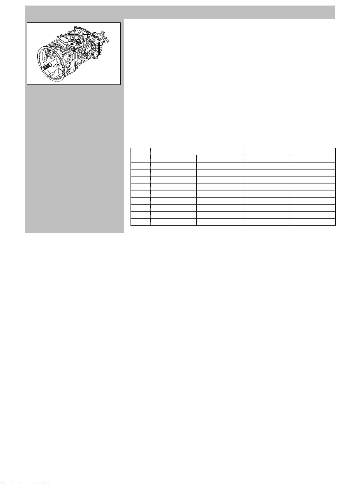
MANUAL TRANSMISSION
1
Clutch
Dry single disk. Diameter 17”.
Hydraulic control.
Gear shift (Fig. 1)
ZF 16 S 1620 TD, ZF 16 S 1820 TO,
ZF 16 S 1920 TD, ZF 16 S 2220 TO,
ZF 16 S 2220 TD, ZF 16 S 2320 TD,
ZF 16 S 2520 TO, ZF 16 S 2720 TO
Syncromesh manual with 8 forward gears,
split into a low range group (1- 4) and a high
range group (5 - 8), and 1 R.G, normal and
low.
Pneumatic servoshift device.
Neutral switch for preventing starting the
motorwithgearengaged.
Hydrodynamic retarder (intarder) mounted
on gearbox output (optional).
Ratios
Direct Drive Over Drive
Normal Low Normal Low
1st 13.80 16.41 11.54 13.80
2nd 9.49 11.28 7.93 9.49
3rd 6.53 7.76 5.46 6.53
4th 4.57 5.43 3.82 4.57
5th 3.02 3.59 2.53 3.02
6th 2.08 2.47 1.74 2.08
7th 1.43 1.70 1.20 1.43
8th 1.00 1.19 0.84 1.00
R.G. 12.92 15.36 10.80 12.92
R.G. = Reverse Gear
1-9
Page 24
1-10
283092101
342ADT001L
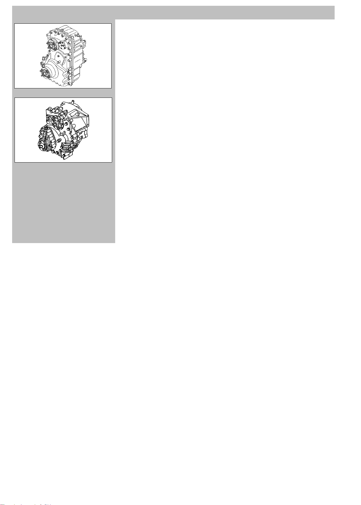
TRANSFER DISTRIBUTOR
1
STEYR VG 2700/400 (Fig. 1)
T ransmissio n ratios:
Normal (on road): 0.913
Low (off road): 1.407
Maximum torque at input:
30.000 Nm
IVECO ZF TC 2200 (Fig. 2)
T ransmissio n ratios:
2
Normal (on road): 1.0
Low (off road): 1.6
Maximum torque on input:
22.000 Nm
HD9 Euro3
Page 25
HD9 Euro3
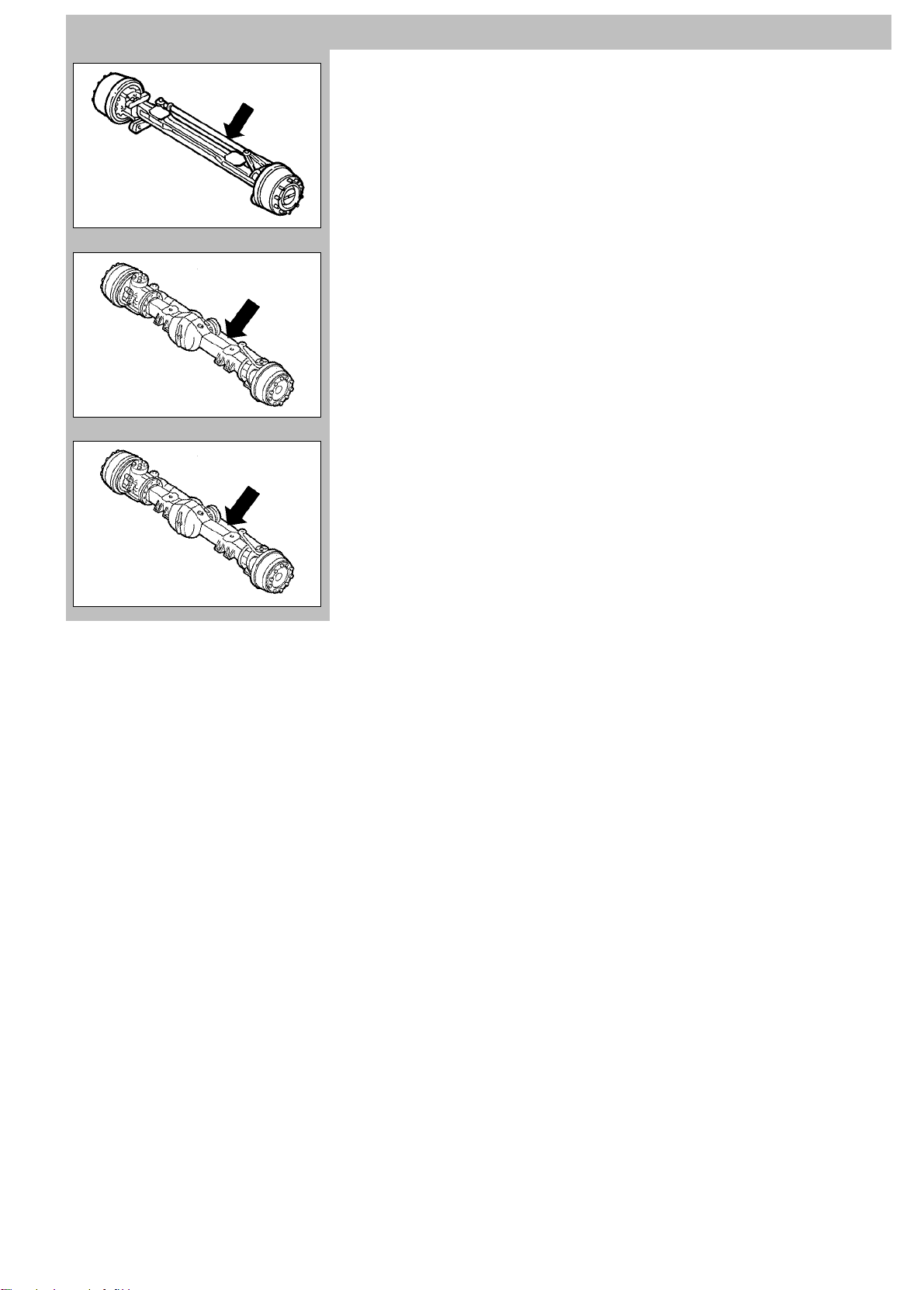
AXLES
1
Front steering axle (Fig. 1)
In high strength drop-forged steel, steering
type, not drive.
Front steering drive axle 9 ton (Fig. 2)
With double reduction (central and final) in
wheel hubs by means of epicyclical gear set.
Drive shafts controlling front wheels
equipped with Cardan joints.
Front steering drive axle 10 ton (Fig. 3)
With double reduction (central and final) in
2
wheel hubs by means of epicyclical gear set.
Drive shafts controlling front wheels
equipped with Cardan joints.
3
1-11
Page 26
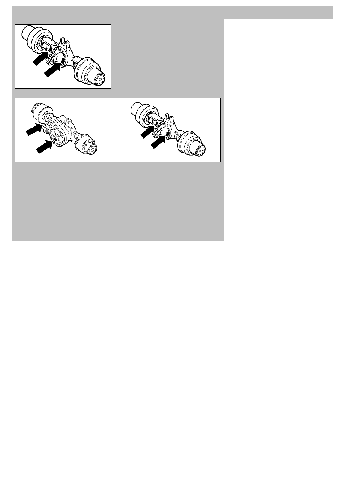
1-12
HD9 Euro3
1
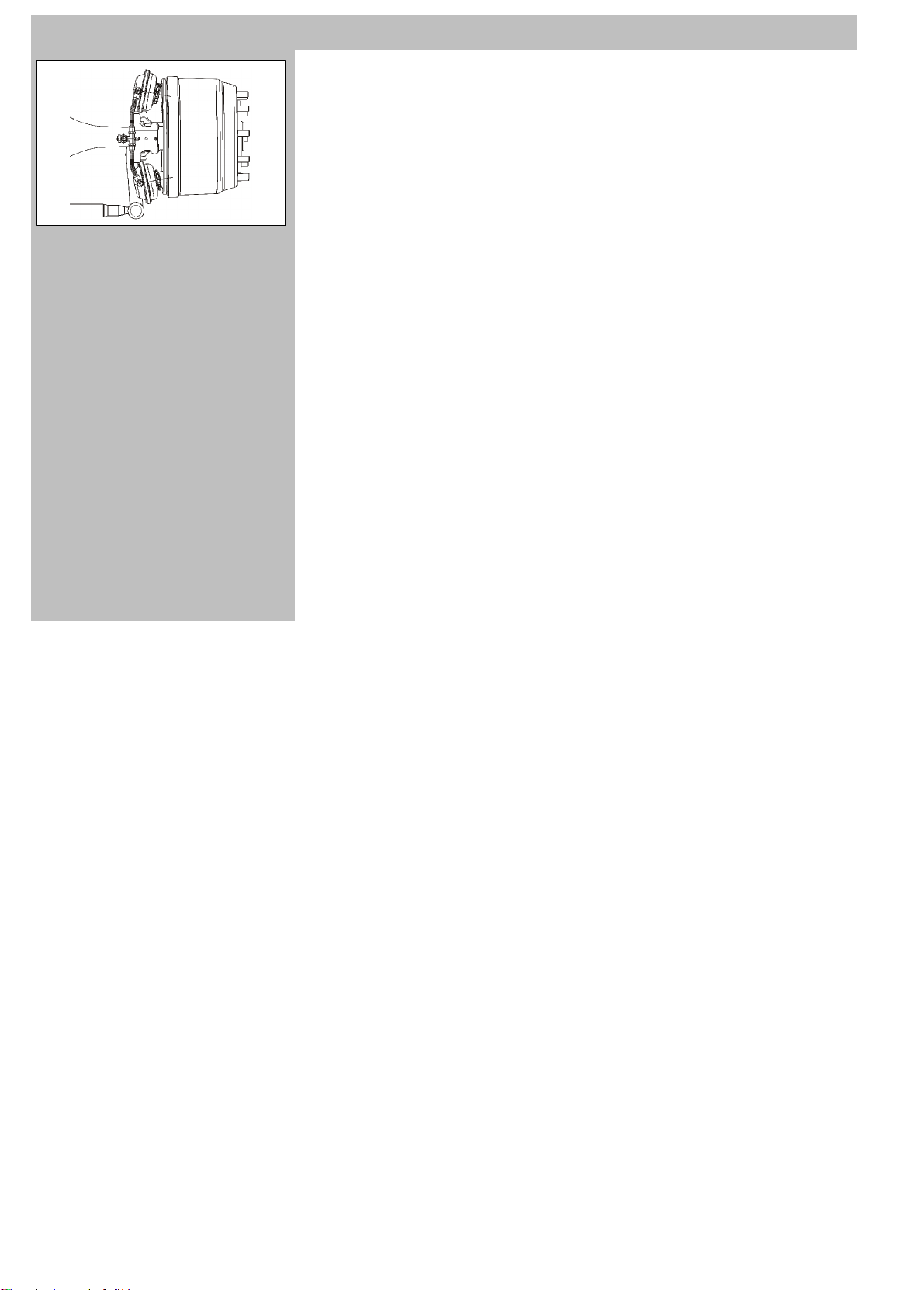
Single rear drive axle (Fig. 1)
With double reduction, central by pinion set
and final in wheel hubs with epycicloid gear.
Differential between wheels with pneumatic
lock.
Tandem rear drive axles (Fig. 2)
Two drive axles in tandem with double reduction, central with bevel gear and final in wheel
hubs with epicyclical gear set.
The tandem is provided with splitter between
axles and pneumatic lock.
Differential between wheels with pneumatic
2
lock.
Page 27
HD9 Euro3
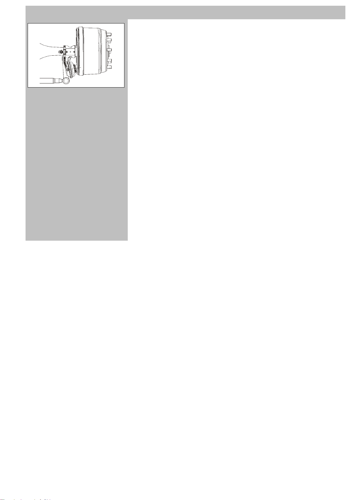
BRAKES (simplex without ABS)
1
Simplex w edge drum brakes (Fig. 1) on all
axles. Brake adjustment is automatic and
therefore maintenance free until total brake
lining wear.
Service brake: pneumatic operation with
two independent sections for vehicles without tow bar, three independent sections for
vehicles with tow bar .
Parking and emergency brake: pneumatic
operation acting on rear wheel brake drums
through spring cylinder.
Engine brake: built into engine.
Retarder brake: hydraulic, installed on tran-
smission.
Auxiliary parking brake: pneumatic opera-
tion: must be engaged with engine running.
1-13
Page 28
1-14
BRAKES (duplex with ABS)
1
Duplex wedge drum brakes (Fig. 1) on all
axles. Brake adjustment is automatic and
therefore maintenance free until total brake
lining wear.
Service brake: pneumatic operation with
two independent sections for vehicles without tow bar, three independent sections for
vehicles with tow bar .
Parking and emergency brake: pneumatic
operation acting on rear wheel brake drums
through spring cylinder.
Engine brake: built into engine.
Retarder brake: hydraulic, installed on
transmission.
Auxiliary parking brake: pneumatic oper-
ation: must be engaged with engine running.
ABS
Wheel anti-lock system (ABS) with four
channel electronic system and four solenoid
valves that exercise the ABS function during
the braking phase.
HD9 Euro3
Pulse generators and sensors on 1st and
2nd axles (2-axle vehicles).
Pulse generators and sensors on 1st and 3rd
axles (3-axle vehicles).
Pulse generators and sensors on 2nd and
4th axles (2-axle vehicles).
Page 29
HD9 Euro3
TYRES
Front: single (*)
Rear: double (**) or single (*)
1-15
DIMENSION
13R22.5
315/80R22.5
CONTINENTAL HSR1 - - 525/65R20.5 MICHELIN XS 8 -
495/45R22.5 MICHELIN XDA2 9 - 525/80R25 MICHELIN XL 7 .
445/65R22.5 MICHELIN XZL 8 - 24R21 MICHELIN XZL 6 .
TYPE
MICHELIN XZY2 8 8
MICHELIN XDY3 8 8 MICHELIN XZY2 8.5 8.5
MICHELIN XZH 8 8 MICHELIN XZL 8.5 8.5
PIRELLI AP05 9 - MICHELIN XZY 8.5 8.5
PIRELLI AT75 - 9 PIRELLI AP05 9 PIRELLI AT99 8.5 8.5 PIRELLI AT75 - 8.5
PIRELLI FG85 9 9 PIRELLI FG85 9 9
PIRELLI TG85 9 9 PIRELLI TG85 9 9
PIRELLI FG88 9 9
PIRELLI TG88 9 9 MICHELIN XDE2TL 9 9
CONTINENTAL HSC - CONTINENTAL HDC - - PIRELLI TG88 9 9
MICHELIN XZY2 8.5 8 20.00R20 CONTINENTAL - MICHELIN XDY3 8.5 8
MICHELIN XZE2 8.5 8 MICHELIN XFA1+ 8.5 -
MICHELIN XDE2 8.5 8 365/85R20 MICHELIN XZL 7.5 -
MICHELIN XDE2+ 8.5 8 365/80R20 MICHELIN XZL 6 -
PIRELLI AP05 8 8 16.00R20 MICHELIN XZL 7.6 7.6
PIRELLI AT75 8 8
PIRELLI FG85 8 8 PIRELLI PS22 PISTA 7 7
PIRELLI TG85 8 8 24.00R20.5 MICHELIN XS 6 -
PIRELLI FG88 8.5 8.5 385/95R24 MICHELIN X 9 -
PIRELLI TG88 8.5 8.5 385/55R22.5 MICHELIN XFA2 9 9
CONTINENTAL HDR - - 395/85R20 MICHELIN XZL 8.5 .
(*)
bar
(**)
bar
DIMENSION TYPE
MICHELIN XDY 8.5 8.5
12.00R20
315/70R22.5
325/95R24
385/68R22.5
14.00R20
MICHELIN XZE2TL 9 9
PIRELLI FG88 9 9
MICHELIN XZY3 9 -
MICHELIN XZL 7.6 7.6
(*)
bar
(**)
bar
Page 30
1-16
345CDT001L
SUSPENSION
1
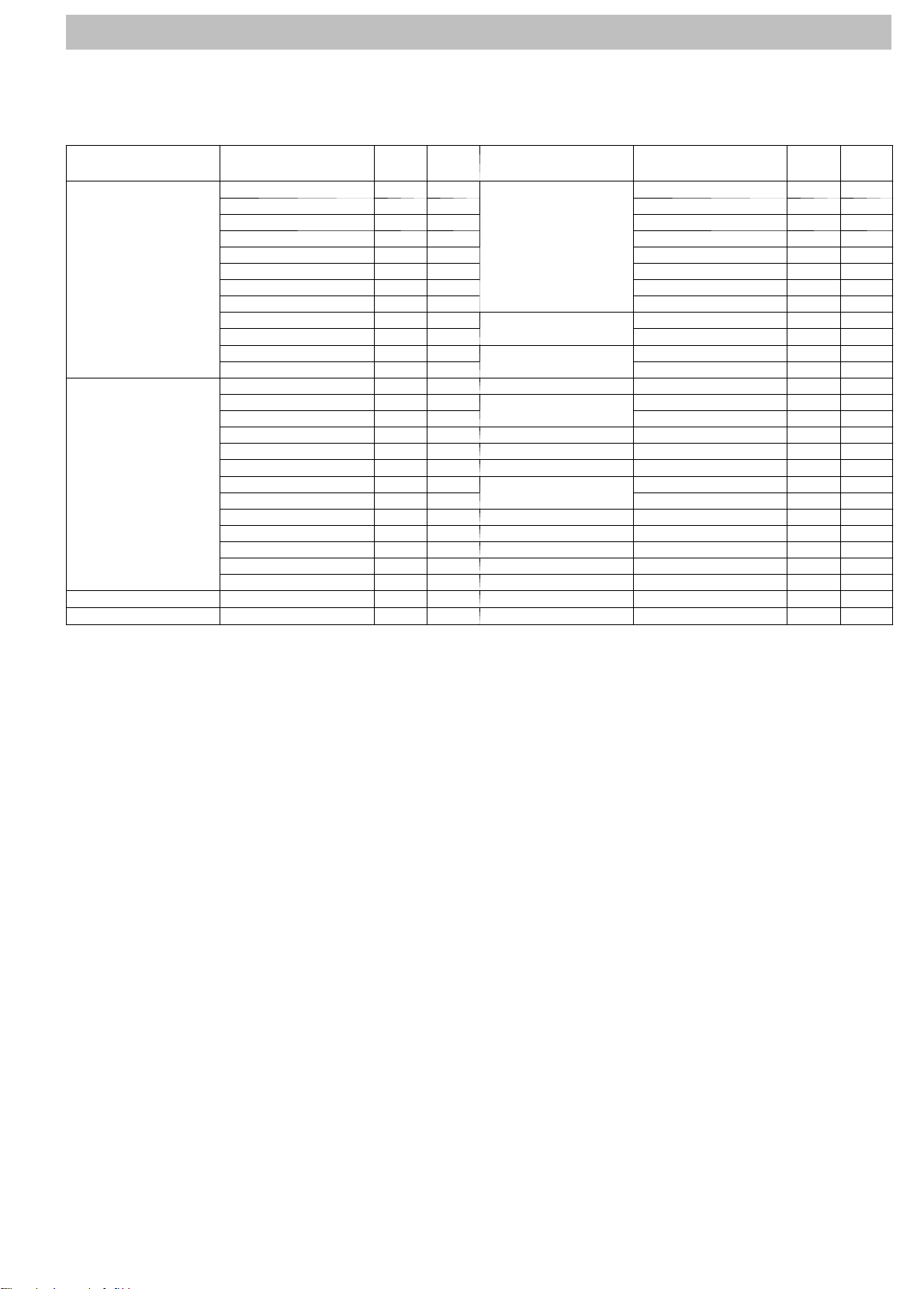
Front (Fig. 1):
Longitudinal single leaf springs. Telescopic
duplex hydraulic shock absorbers and roll
bar.
Rear:
2-axle vehicles (Fig.
Longitudinal double leaf springs.
Telescopic duplex hydraulic shock
absorbers and roll bar.
2
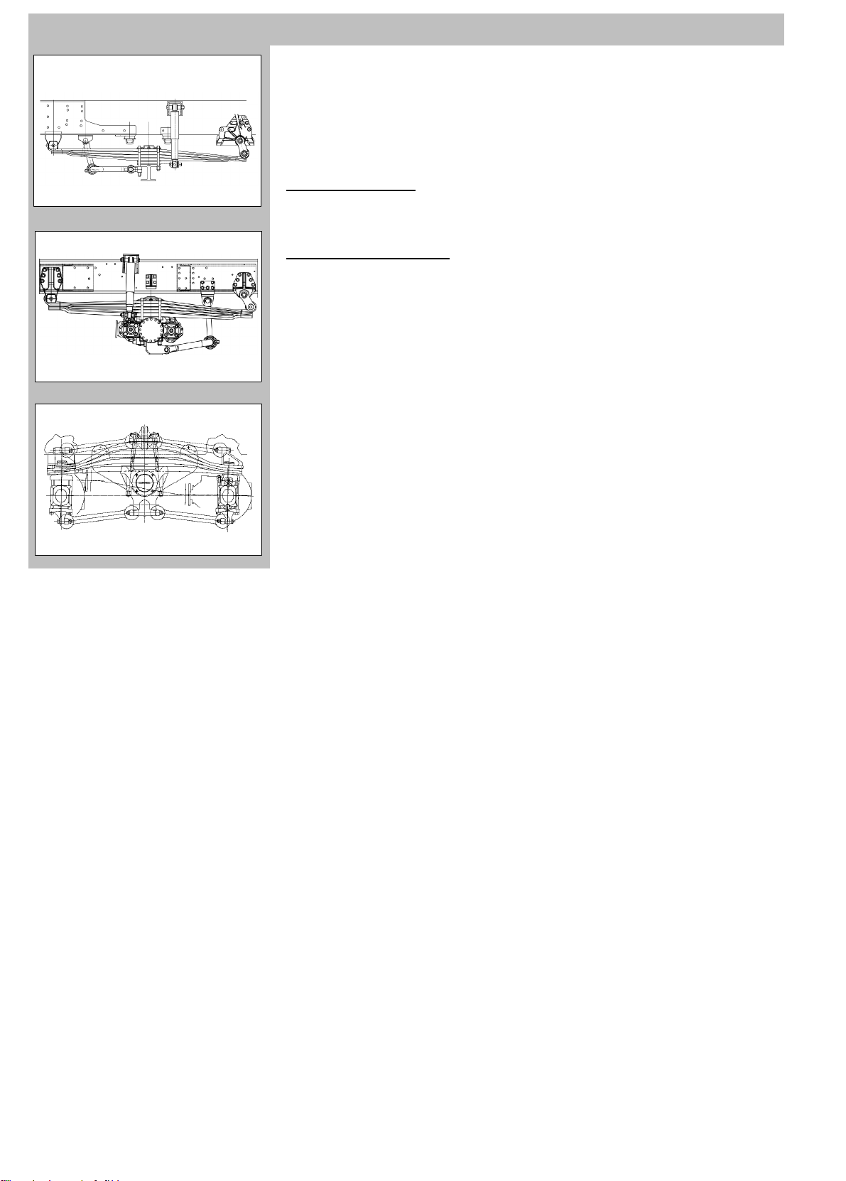
3and4axlevehicles(Fig.
Single leaf springs, individual for the two
rocking axles with rocker system.
The torque bars between axle and central
support counteract the axial thrust on acceleration and braking.
Anti-roll bar on intermediate axle and on rear
axle (upon request).
Leaf spring: parabolic or semi-elliptic (upon
request).
2):
3):
3
HD9 Euro3
345FDT007L
Page 31

HD9 Euro3
STEERING
1
ZF hydraulic ball bearing mounted power
steering.
Vehicles without auxiliary cylinder
Type: 8098 (Fig. 1)
Oil pump driven by engine.
Front wheel steering with quadrilateral kinetic motion assembly.
Vehicles with auxiliary cylinder
2
Type: 8099 (Fig. 2)
Oil pump driven by engine.
Emergency pump driven by transmission.
Front wheel steering with quadrilateral kinematic motion assembly.
Auxiliary cylinder.
1-17
Page 32

1-18
ELECTRICAL SYSTEM
1
Nominal voltage: 24 V
Accumulators (Fig. 1) (n˚ 2):
12 V --- 170 Ah or
12 V --- 220 Ah
A l t e r n a t o r : 28 V --- 9 0 A
HD9 Euro3
274CNU102
Accumulator and alternator features may
change according to the outfitting and
market of destination.
Starter motor
24V - -- 4.5 kW (engine F2B)
24V - -- 5 kW (engine F3B)
Ground reference: negative pole.
Page 33

HD9 Euro3
CHASSIS (Fig. 1)
1
Built with rectilinear side members in high
strength “C” section steel, connected by
riveted or bolted cross-members.
Standard fuel tank
Steel, capacity 300 liters with level and
reserve indicator.
Oversize fuel tank
Steel, capacity 600 liters with level and
reserve indicator.
1-19
Page 34

1-20
TIGHTENING TORQUES
HD9 Euro3
Assembly
Engine
Multipower power take-off
ZF manual transmission
ZF iIntarder
ZF As-T ronic automated transmission
Allison automatic transmission
IVECO splitter
ZF splitter
Wheels
Front axle (Iveco)
Element Type
To r q u e
(Nm)
F2B engine oil magnetic drain plug
F3B engine oil magnetic drain plug
Magnetic oil drain plug
Oil filler cap 25 ÷ 30
Oil drainage, level and filler caps 80
Oil magnetic drain plug on clutch bell M38x1.5 140
Oil filter cover fastening screw
Oil drain plug M25x1.5 60
Side oil drain plugs
Bottom oil drain plug
Filler and level cap
Oil filter cover fastening screw 20 ÷ 25
Oil drain plug 25 ÷ 32
Filler and level cap
Oil drain plug M14x1.5 54 ÷ 66
Magnetic oil drain plug M27x2 90 ÷ 110
Oil filler and level cap M22x1.5 63 ÷ 77
Oil drain plug M22x1.5 60
Oil filler and level cap M22x1.5 60
Fasteners (nut and washer) 580 ÷ 650
Fasteners (countersunk nut) 380 ÷ 450
Magnetic oil drain plug
Oil filler and level plug
Oil drain plug on transfer case
Oil level plug on transfer case
Page 35

HD9 Euro3
1-21
Assembly
Frontintermediateaxle(Iveco)
Rear intermediate axle (Iveco)
Rear axle (Iveco)
Front axle (Kessler)
Intermediate axle (Kessler)
Rear axle (Kessler)
Element Ty p e
To r q u e
(Nm)
Magnetic oil drain plug
Oil filler and level plug 72 ÷ 88
Oil drain plug on transfer case
Oil level plug on transfer case
Magnetic oil drain plug
Oil filler and level plug 100 ÷ 120
Oil drain plug on transfer case
Oil level plug on transfer case
Magnetic oil drain plug
Oil filler and level plug 36 ÷ 44
Oil drain plug on transfer case
Oil level plug on transfer case
Magnetic oil drain plug M16x1.5 60
Oil filler and level plug M30x1.5 160
Oil drain plug on transfer case M16x1.5 60
Oil level plug on transfer case M24x1.5 120
Magnetic oil drain plug M16x1.5 60
Oil filler and level plug M30x1.5 160
Transfer case oil drainage cap M24x1.5 120
T ransfer case oil filler and level plug M24x1.5 120
Oil drain plug on transfer case M16x1.5 60
Oil level plug on transfer case M24x1.5 120
Magnetic oil drain plug M16x1.5 60
Oil filler and level plug M30x1.5 160
Oil drain plug on transfer case M16x1.5 60
Oil level plug on transfer case M24x1.5 120
Page 36

1-22
VEHICLE OUTFITTING
Each vehicle is equipped with a set of toolsand
wrenches so that the Customer can carry out
the normal maintenance operations.
D Lifting j ack.
D Cab tilting jack/rod and wheel wrench.
D n˚ 2chocks.
D Instructionsfor USE AND MAINTENANCE
HANDBOOK.
D Log-book holder.
Keys
Each vehicle is supplied with:
D Ignition/door/fuel filler cap keys (3).
D Door lock remote control (optional).
HD9 Euro3
Page 37

HD9 Euro3
1-23
Instructions for use
Page 38

1-24
HD9 Euro3
Page left intentionally blank
Page 39

HD9 Euro3
1-25
GENERAL INSTRUCTIONS FOR CORRECT USE OF THE VEHICLE
Before driving
Adjust the seat, steering wheel and rear-view mirrors to obtain a correct driving position.
Check that there are no obstructions to pedal excursion, in particular the brake pedal.
Check that the horn works correctly.
Check that all external lights function correctly, and if necessary clean the lighting groups.
Check, especially when travelling by night, that headlights are correctly aligned.
Check that no oil or fluids are leaking from under the vehicle.
Check that any cargo is correctly stowed.
Check that the handbrake is on and that no dashboard warning light indicates a fault.
To prevent accidental vehicle movements, disengage the handbrake with the brake pedal pressed.
Do not apply transfers or stickers to the windscreen: these could distract or impair vision.
When driving
Long journeys should only be undertaken in ideal physical conditions.
Light, easily digestible meals help in keeping reflexes ready as well as maintaining the concentration required for safe driving.
Never drive for too many consecutive hours, but make frequent stops, taking the opportunity to stretch and generally refresh.
Make use of the wide range of adjustments offered by the heating, ventilation or air-conditioning system to maintain constant cabin air
change.
The abuse of alcohol, drugs and or certain medicines is extremely dangerous. Never undertake a journey under the influence of alcohol,
pharmaceuticals or drugs.
Careful driving also means being in a condition to foresee the mistakes or carelessness of other drivers.
Always observe speed limits and always drive in the slow lane on motorways.
Always use indicators when changing direction or lane.
Keep a safe distance from the vehicle in front. This distance varies according to speed, weather, traffic and road conditions.
Never drive with the gearbox in neutral.
Never freewheel downhill: With the engine off there is no engine braking, requiring greater force on the brake pedal.
Use engine braking by engaging a low gear to avoid overheating the brakes.
In case of breakdown, park the vehicle off the carriageway, switch on the hazard warning lights and set up the red reflecting triangle sign
to warn other drivers. Always follow the Highway Code.
Page 40

1-26
HD9 Euro3
Night driving
Take special care, reducing speed if necessary, especially on unlit roads.
Keep a greater safety distance than when driving by day: in effect it is more difficult to estimate the speed of an approaching vehicle when
only its lights are visible.
Stop and rest as soon as you feel tired. To continue would only be a hazard to yourself and others.
Use high beams only outside built-up areas an only when you are sure they do not other drivers.
Always dip headlights with oncoming traffic.
Driving in rain, fog and snow
If the road is wet the grip between the tyres and the road surface is significantly reduced, so braking distance is greater and grip when turning
is reduced. Reduce speed and keep a greater distance from the vehicles in front.
Heavy rain and fog reduce visibility. In compliance with the Highway Code, switch on dipped headlights even by day to render your vehicle
more visible.
Do not drive through puddles or flooded sections of road at high speed. Aquaplaning may cause loss of control. Use engine braking and
in all cases avoid braking sharply .
Set ventilation controls to ensure efficient windscreen demisting.
Before starting out, check the condition of windscreen wipers. If temperature is below 0˚, or if it is snowing, check that the wiper blades and
not frozen against the windscreenProceed with extreme caution in case of fog. Moderate speed and avoid overtaking if possible.
Check that windscreen/headlight washer fluid contains antifreeze and anti-scale products.
In winter, even apparently dry roads may have icy patches, especially sections in the shade or lined by trees or rocks.
Parking
Switch off the engine.
Engage the parking brake.
Engage 1st gear if the vehicle is parked on a slope or reverse gear if the vehicle is facing downwards (manual gearshift vehicles only).
Never leave the key turned to MAR with the engine off to avoid flattening the batteries.
Tyr e s
Always reduce speed before taking on a tight bend, even if vehicle performance permits.
Avoid sharp acceleration of heavy braking.
Do not drive at constant high speeds for long periods, especially on uneven road surfaces.
Make certain that wheels are correctly balanced and adjusted.
Avoid violent impacts to tyre walls (for example when parking).
Nevertamperwithtyreinflationvalves.
Page 41

HD9 Euro3
1-27
Do not insert any kind of tool between tyre and wheel rim.
If the rim is damaged, replace it.
If a tyre loses pressure for no apparent reason, replace the wheel and check the faulty tyre.
Tyre pressures, including the spare, must always be as specified.
Tyres that are old (over 6 years) or used should only be used in case of emergency and with due caution.
Do not leave the vehicle parked for long periods on the edge of the kerb or similar irregularities on the road surface.
Regularly check tyre tread depth, changing tyres when depth is less than the legal minimum.
The vehicle mounts ’tubeless’ tyres, meaning without inner tube. Inner tubes must not be fitted to tubeless tyres.
Certain types of tyres are fitted with wear indicators. They must be changed as soon as the indicators become visible on the tread.
Aquaplaning is more likely with worn tyre treads.
Snow chains
The use of snow chains is governed by local law in each country.
Chains should only be fitted to drive wheels.
To prevent tyre damage, do not drive on clear roads with chains fitted. In extreme cases (tunnels, etc....) proceed at low speed and in any
case remove the chains as soon as conditions permit.
Maintain moderate speed with chains mounted, avoiding potholes and driving onto the kerb.
Certain tyres of snow chain require tension adjustment after travelling a short distance.
Economic, ecological driving
Road conditions and driving style have a direct influence on fuel consumption and environmental impact.
Carry out the maintenance operations described below at regular intervals and with care.
Do not demand maximum power from the vehicle with the engine cold.
Do not rev the engine when parked.
Always avoid sharp acceleration and repeated braking/acceleration. Engage a higher gear as soon as conditions permit.
If possible, avoid driving with side windows lowered. Use the air-conditioner/ventilation system to obtain the desired conditions in the cab.
Engage a high gear whenever traffic and road conditions permit.
Limit the use of high power absorption utilities (air-conditioner on full, for example) when driving in city traffic or behind slow moving vehicles.
Revving the engine between gears or before stopping the engine serves absolutely no purpose.
Avoid accelerating on full throttle. Fuel consumption will be significantly lower with gradual acceleration.
Page 42

1-28
Rangeofuseoftheengine
1
The following table shows indications for
correct engine use.
a white sector: minimum, low use
b green sector: economic running
c yellow sector: maximum engine speed
range
d red sector: runaway rate
HD9 Euro3
The best performance/consumption ratio
is obtained when the engine rate is in the
green sector.
NEVER USE RED SECTOR.
Engine
F2B/F3B 0 - 1200 1200 - 1900 2400 - 3000 3000 - 3200
White Green Yellow Red
Tachometer sector (RPM)
Page 43

HD9 Euro3
342BNU001L
2
LEFT HAND DRIVE VEHICLES
1
CAB-EXTERNAL
Thecab(Fig.1)ishingedatthefrontand
suspended both to front and rear on the
chassis:
D to the front by two longitudinal arms with
springs, shock absorbers and buffers.
D to the rear by two control arms with
springs, shock absorbers and buffers.
The cabin can be tipped forward by means
of a manually controlled hydraulic cylinder.
Always use the grips and steps (Fig. 2, see
arrow) specifically designed to permit easy
accessibility to get on and off the vehicle.
1-29
Always keep handles and foot-boards
clean to avoid slipping.
342BNU001L
Page 44

1-30
HD9 Euro3
1
1
EXTERNAL LIGHTING
Front lights (Fig. 1)
1. High beam
2. Parking light and headlight
3. Front direction indicator
4. Side direction indicator
5. Front clearance light
6. Rotary warning lights (if fitted)
342BNU009L
Page 45

HD9 Euro3
1-31
1
1
Rear lights (Fig. 1)
1. Direction indicator
2. Stop light
3. Side light
4. Fog warning light
5. Reversing light
6. Licenseplatelight(onesideonly)
7. Side clearance
228NU205
Page 46

1-32
342BNU004L
DOORS
1
The vehicle has two doors symetrically
placed at each side.
The external door handle (Fig. 1, see arrow)
can be locked from the outside with a key.
To open the door pull down the external
handle.
D to block the lock, turn the key anticlock-
wise(Fig.1,ref.1);
D to block the lock, turn the key clockwise
(Fig.1,ref.2);
D to open the door, pull handle downward.
When the door is opened the cabin interior
light comes on automatically, along with the
cabin step lights.
HD9 Euro3
Page 47

HD9 Euro3
342BNU005L
The inner side of the door has the following
1
controls (Fig. 1):
1. Door opening handle
2. Electric window control
3. Door closing handle
4. Knob for locking doors from the inside
5. Electric mirrors adjustment control (only
driver’s door)
1-33
Page 48

1-34
272CNU001
Central locking remote control
1
Briefly press the button (Fig. 1, ref. 1) on the
remote control, while pointing the control in
the direction of the vehicle, the direction indicators will flash simultaneously indicating
that all doors are unlocked.
To lock the doors press the button (Fig. 1 ref.
2) still while pointing the control in the direction of the vehicle, the direction indicators will
flash simultaneously indicating that all doors
are locked.
HD9 Euro3
Page 49

HD9 Euro3
272CNU002
Replacing remote control battery
1
D Insert a small coin or screwdriver into the
slot on the side of the remote control and
open it (Fig. 2).
D Replace the battery, paying attention to
the polarity.
D The remote control has a lithium battery.
CR 2032 3V
D Close the two halves of the remote control
checking that they are correctly coupled.
1-35
A reduction in range of the remote control
is an indicator that the battery is almost
exhausted.
Exhausted batteries are harmful to the
environment. Exhausted batteries must
be disposed of as required by law. Or it
canbehandedovertotheServiceNetwork that will provide for correct disposal.
Page 50

1-36
DRIVERS SEAT
HD9 Euro3
1
342BNU006L
Page 51

HD9 Euro3
DRIVER’S SEAT (Fig. 1 previous page)
1. Driver’s seat adjustment controls
2. Steering wheel position control
3. Ashtray
4. Cigarlighter-12Vpowersocket-Diagnosticsocket
5. Gear lever
6. Differential lock / splitter / supplementary parking brake
7. Climate control system controls
8. Parking brake
9. Document holder
10. Controls lever Cruise control / retarder
11. Ignition switch
12. Dashboard
13. Steering wheel
14. Instrument panel
15. Controls lever lights / headlights / direction indicators / windscreen wiper controls
16. Pedal controls
1-37
Page 52

1-38
HD9 Euro3
1
1
1
342BNU007L
2
INTERNAL LIGHTING DEVICE
Upper dashboard (Fig. 1)
1. Ceiling light
Press button (Fig. 2) to switch on the ceiling
light.
Press again to switch off the ceiling light.
2. Access step lighting
The light switches on when the door is
opened.
342BNU008L
Page 53

HD9 Euro3
1-39
1
341DNU020L
EXTERNAL REAR VIEW MIRRORS
The vehicle is fitted with the following external rear view mirrors (Fig. 1, 2 and Fig. 3):
1 Left side wide-angle mirror
2 Main left side mirror
3 Right side wide-angle mirror
4 Main right side mirror
5 Right pull-in mirror
Page 54

1-40
342BNU050L
2
Mirror selection and handling
1
Using the mirror selection control (Fig. 1, ref.
1) brings up a specific page on the techometerLCD(Fig.2,ref.1).
Use the mirror adjustment control (Fig. 1, ref.
2) to adjust the selected mirror.
HD9 Euro3
This adjustment must be made with vehicle stationary.
Without remote control the driver has to
adjust the mirrors manually.
285ANU002L
Page 55

HD9 Euro3
285ANU003L
284CNU004L
The selected mirror is identified by the num-
1
ber on the LCD (Fig. 1, ref. 1)
The selected mirror is graphically highlighted on the LCD (Fig. 1, ref. 2).
The mirrors controlled by the system are
(Fig. 2):
1. Main driver’s mirror
2. Driver’s wide-angle mirror
3. Main passenger side mirror
4. Passenger side wide-angle mirror
2
Press the mirror heater button (Fig. 1, ref. 3)
to rapidly demist the mirrors. Press the button to turn the mirror heating system on.
Press the button again to turn the mirror
heating system off.
3
1-41
342BNU051L
Page 56

1-42
HD9 Euro3
1
342BNU010L
SEATS
Fore and aft adjustment
Lift lever (Fig. 1, ref. 1) to have the seat free
to move backwards or forward.
Release the lever and ensure the mechanism is fully.
Cushion angle adjustment
The cushion angle may be adjusted by lifting
lever (Fig. 1, ref. 2) and pulling and pushing
the backrest (12˚ max.). Release the lever
after adjustment.
Seat suspension adjustment
Lift lever (Fig. 1, ref. 3) to lower and lock the
seat; lower the lever to raise the seat (set
beforehand with lever 5).
Page 57

HD9 Euro3
1-43
1
342BNU010L
Springing system adjustment
Springing system adjustment is obtained by
lifting or lowering lever (Fig. 1, ref. 4):
D Lever up = Maximum suspension effect.
D Lever down = Minimum suspensions
effect.
With this device seat suspension is
according to road surface and weight of
the driver. The shock absorber has to be
adjusted rigidly, to avoid that on rough
surfaces the seat hits the end of stroke,
jeopardising the spring system.
Height adjustment
Lift lever (Fig. 1, ref. 4) to raise the seat; release the lever after adjustment. Seat height
is memorised automatically.
Lower lever to lower the seat (100 mm max.)
Backrest angle adjustment
Lift lever (Fig.1, ref. 5) and set the backrest to
the desired angle with your back. Release
the lever to block the backrest.
Page 58

1-44
SEAT BELTS
1
The vehicle is equipped with three-point seat
belts and automatic reel (Fig. 1).
D To fasten the belt grip the tab and insert it
into the buckle until it clicks (Fig. 2).
D To release the belt, press the button on the
top of the buckle (Fig. 3).
HD9 Euro3
178NU08
2
178NU09
178NU10
Do not adjust the mirrors while driving.
3
Page 59

HD9 Euro3
178NU08
The belt does not need to be adjusted by
1
hand: the webbing adjusts itself automatically to the length most suited to the driver
allowing him freedom of movement provided that his movements are not abrupt.
The belt mechanism is affected by changes
in vehicle attitude and as a consequence the
belt may lock in the following cases:
D sudden braking or acceleration;
D vehicle driving on a slope;
D when cornering.
1-45
Thebeltmustnottwistandmustadhere
to the hips, not the abdomen, to prevent
the risk of slipping forwards.
Occasionally check that the anchor bolts
are fully tightened and that the belt itself
is not cut or frayed.
In case of accident of a certain gravity,
replace the belt involved, even if it does
not appear damaged.
Do not make alterations likely to reduce
seat belt efficiency
Page 60

1-46
ELECTRIC WINDOW CONTROL
1
Electric window risers control
Left side (Fig.
1. Left side window control
2. Right side window control
1)
HD9 Euro3
342BNU011L
342BNU012L
342BNU013L
Right side (Fig.
1. Right side window control.
Press (Fig. 3, ref a) the switch to lower the
2
glass.
Pull the switch upward (Fig. 3, ref b) to raise
the glass.
The glass stops when the switch is released.
2)
3
Page 61

HD9 Euro3
178NU02
2
272NU102X
HATCH
1
To open the hatch turn the handle (Fig. 1, ref.
1) anti-clockwise.
To close the hatch proceed as follows:
D Turn the handle clockwise until closing the
hatch.
D Return the handle to its original position
(Fig. 2).
D Turnthehandleatmostbyaquarterturn
until reaching the stop (Fig. 3, arrow).
D Return the handle to closed position and
lock it by tipping the knob.
3
1-47
Toescape from the cabin in an emergency
turn the full release handles downward
(Fig.1,ref.2)andpushthehatchoutwards.
272NU103X
Page 62

1-48
HD9 Euro3
1
342BNU014L
2
COMPARTMENTS
Dashboard (Fig. 1)
1. Bottle/can holder
2. Mobile phone holder
3. Items tray (according to outfitting)
4. Gloves compartment
5. Compartment in front of passenger
Upper dashboard (Fig. 2)
1. Compartment in front of passenger
(closed with lid).
Act on button and raise lid to open.
Lower lid and press until it clicks into
place.
2. Loose items tray (according to outfitting)
342BNU015L
Page 63

HD9 Euro3
1-49
342BNU016L
1
2
Door (Fig. 1)
1. bottle holder
2. pocket
3. pocket
Tunnel (Fig. 2)
1. coin holder
2. loose items tray
Seat (Fig. 3)
1. Compartment (closed with lid)
Act on button and lower lid to open.
Raise lid and press until it clicks to close.
2. items holder
Rear wall (Fig. 4)
1. bottle holder
2. items compartment
3
4
342BNU017L
342BNU018L
342BNU019L
Page 64

1-50
HD9 Euro3
1
342BNU020L
2
ACCESSORIES - DEVICES
Sunblindtabs(Fig.1,ref.1)
Grip the front edge of the tab and turn downward.
Bring to position by hand.
Griphandle(Fig.1,ref.2)
On passenger side.
Coathook(Fig.1,ref.2)
On both sides of cab.
Cigarlighter(Fig.2,ref.1)
Press to activate cigar lighter: a click indicatesitisreadyforuse.
After use return to its seat without pressing.
Ashtray (Fig. 2, ref. 2)
On both sides of cab.
Raise lid to open.
Lower lid to close.
12Voltcurrentsocket(Fig.2,ref.3)
Open cap and insert facility .
After use close cap.
342BNU021L
Page 65

HD9 Euro3
1-51
1
342BNU022L
CONTROLS
Controls on dashboard (Fig. 1)
1. Headlamps geometry adjustment
2. External lights switch
3. Hazard lights
4. Parking brake control
Page 66

1-52
HD9 Euro3
1
1
Module holder dashboard controls
(Fig. 1)
1. Engine brake switch
2. Fog light switch
3. Rear fog light
4. Mirrors heating switch
5. Horn selector switch
6. Pivoting headlamps switch
7. Ceiling light switch
8. Not used
9. Not used
10. PTO activation switch
11. PTO 1 activation switch
12. PTO 2 activation switch
13. ABS switch (OFF-ROAD)
14. ASR switch
15. Additional parking brake switch
16. Work light switch
17. Electric battery master switch
18. Not used
19. Climate controls
20. Not used
21. 12 V current socket
342BNU023L
Page 67

HD9 Euro3
Controls on roof (Fig. 1)
1
1. Radio CD equipment housing
2. CB housing
3. Tachograph housing
1-53
342BNU024L
272NU061X
Controls on
Steering wheel position control
Steering wheel position adjustment is pneumatic, and can be regulated by means of the
button on the floor at the base of the steering
column, driver’s side.
1
Proceed as follows:
D With the button pressed (Fig. 2, ref. 1) take
the wheel in your hands and bring it to the
required position.
D Once in position, release the button.
floor
This operation can only be done with:
D sufficient air pressure;
D parking brake engaged.
Page 68

1-54
272NU062X
Accelerator
1
The accelerator is controlled by means of a
pedal on the floor to be operated by the
driver’srightfoot(Fig.1,ref.1).
Press the pedal to increase the torque output
by the engine proportionally to the position
of the pedal.
Service brake
The service brake is controlled by means of
a pedal on the floor to be operated by the
driver’srightfoot(Fig.1,ref.2).
Press the pedal to obtain a braking effect in
proportion to the exerted pressure.
Clutch
The clutch is controlled by a pedal to be
operated with the driver’s left foot (Fig. 1, ref.
3).
Press the pedal to release the clutch. Only for
manual trasmission vehicles.
HD9 Euro3
Page 69

HD9 Euro3
1
342BNU025L
1-55
Manual transmission control
Transmission is controlled by a manually
operated lever. (Fig. 1, see arrow).
By shifting the lever, the different gears are
engaged.
The lever also has a splitter pre-selection
lever. Acting on this lever pre-selects the
engagement of reduced gears range, actuated through the clutch pedal.
Page 70

1-56
ALL VEHICLES
INSTRUMENTS
Instrument panel (Fig. 1)
HD9 Euro3
1
1
341DNU001L
341DNU001L
Page 71

HD9 Euro3
Instrument panel (Fig. 1)
1) Front axles brake wear warning light
Red light indicates front brakes have reached the wear limit
2) Rear axles brake wear warning light
Red light indicates rear brakes have reached the wear limit
3) Rear axle brakes air pressure indicator.
4) Front axle brakes air pressure indicator.
5) ABS failure warning light
Yellow light indicates ABS system is not functioning
6) Braking system failure warning light
Red light indicates there is a failure in the braking system
7) Rev counter
8) Digital speedometer
9) LCD screen with hour-counter and partial trip display
10) Partial trip reset button
11) Fuel level indicator
12) Fuel reserve warning light
Red light indicates fuel tank level is in reserve
13) Engine water overheating
Red light indicates the engine water is overheated
14) Engine water temperature indicator
15) Instruments illumination adjustment button
A) Warning lights panel A
B) Warning lights panel B
C) Warning lights panel C
1-57
See the below for further information
regarding instrument panel.
Page 72

1-58
Functions of instrument panel keys
1
Key1(Fig.1,ref.
Instrument illumination adjustment.
or
Error memory display.
285ANU009L12
Key2(Fig.1,ref.
Press key 2 for less than three seconds to
2
display trip km or total km
Trip odometer reset
With trip odometer displayed on LCD (Fig. 2,
ref. 1), press key 2 for more than three seconds to zero the indicated distance.
Units of measure conversion (Km To convert the units of measure displayed on
the LCD, proceed as follows:
D With ignition key out, press both buttons
(Fig.1,ref1and2).
D Holding the buttons down, turn the key to
MAR and wait 10 seconds.
1):
2):
1
HD9 Euro3
Refer to the DIAGNOSTIC chapter for more information
miles)
285ANU010L
Page 73

HD9 Euro3
341DNU002L
Warning lights panel A details
1
1 Automatic gear converter functioning warning light.
Yellow light indicates lock-up clutch is not engaged.
2 Retarder on warning light.
Y ello w. Indicates that hydraulic retarder is active.
3 Engine brake engaged warning light.
Yellow. Indicates that the engine brake is engaged.
4 Rear traverse differential locked warning light.
Yellow. Indicates that the rear differential clamp is engaged.
5 Transfer box longitudinal differential locked warning light.
Yellow. Indicates that the transfer box differential clamp is engaged.
6 Tandem longitudinal differential locked warning light.
Yellow. Indicates that the tandem longitudinal differential is engaged.
7 External lights on warning light.
Green. Indicates that the side lights (and dip headlights) are on.
8 Mainbeamonwarninglight.
Blue. Indicates that main beam headlights are on.
9 Parking brake engaged warning light.
Red. Indicates that the parking brake is engaged.
10 Left direction indicator warning light.
Green. Indicates that the left direction indicator has been activated.
11 Power steering main circuit failure warning light.
Red. Indicates there is a failure on the power steering main circuit.
12 Power steering emergency circuit failure warning light.
Red. Indicates there is a failure on the power steering emergency circuit.
1-59
Page 74

1-60
1
2
43
285ANU012L
Warning lights panel B details
1
1. Seat belt not fastened warning light
Red. Indicates that the driver’s seat belt is not fastened.
2. Warning light
Y ellow. Indicates a general vehicle fault.
3. Preheating on warning light
Yellow. Indicates that the engine preheating system is active.
4. ECM warning light
Y ellow. Indicates an ECM malfunction.
HD9 Euro3
Page 75

HD9 Euro3
341DNU003L
Warning lights panel C details
1
1. Second speed limit engaged warning light.
Yellow. This indicates that the second speed limiter is engaged.
2. ABS off warning light.
Y ellow. Indicates ABS off.
3. ASR off warning light
Y ellow. Indicates ASR off.
4. Engine oil temperature high warning light.
Red. Indicates that the engine oil temperature is high.
5. Low trailer brake air pressure warning light.
Red. Indicates trailer air brake malfunction.
6. Power steering oil level low warning light.
Red. Indicates that the power steering oil level is insufficient.
7. Alternator warning light.
Red. Indicates that the current delivered to the alternator is insufficient.
8. Water in fuel pre-filter warning light.
Yellow. Indicates the presence of water in the fuel pre-filter.
9. Hazard lights on warning light.
Red. Indicates that the hazard warning lights are on.
10. Right direction indicator warning light.
Green. Indicates that the right direction indicator has been activated.
11. Cab unhooked warning light
Red. Indicates that the cab has not been secured correctly.
12. Air filter clogged warning light
Yellow. Indicates that the engine air filter is clogged.
1-61
Page 76

1-62
341DNU004L
1
Warning lights on dashboard
1. PTO 1 on gearbox engaged warning
light.
Yellow light indicates that PTO 1 on
gearbox is engaged.
2 PTO 2 on gearbox engaged warning
ligh.
Yellow light indicates that PTO 2 on
gearbox is engaged.
3 PTO on flywheel engaged warning light.
Yellow light indicates that PTO on flywheel is engaged.
4 Splitter unit reduced gear ratio engaged
warning light.
Green light indicates that splitter unit
reduced gear ratio is engaged.
5 Low range engaged warning light.
Green light indicates that the gear low
range is engaged.
6 Reduced gears engaged warning light.
Green light indicates that the gearbox
reduced gears are engaged.
7 T railer ABS failure warning light.
Yellow light indicates that the trailer ABS
system is not functioning.
8 Windshield washer liquid level warning
light.
Red light indicates that windshield
washer liquid level is low.
9 Front transverse differential locked war-
ning light.
Yellow light indicates that front differential lock is engaged.
HD9 Euro3
Page 77

HD9 Euro3
1-63
Page left intentionally blank
Page 78

1-64
CONTROL OPERATION
1
Position and headlight controls (Fig. 1)
The control has three positions:
D position 0: off;
D position 1: first click: position lights on;
D position 2: second click: headlights on.
HD9 Euro3
272NU043X
1
Headlight control (Fig. 2)
The control has three positions.
D position 0: normal headlights;
2
D position 1 (light push forward): high
beams;
D position 2 (pull lever back): Beam flasher.
0
2
272NU044X
Page 79

HD9 Euro3
1-65
1
0
2
272NU045X
Direction indicator control (Fig. 1)
1
The control has three positions:
D position 0 off;
D position 1 (up) right direction indicators;
D position 2 (down) left direction indicators.
Horn (Fig. 2)
The horn can be sounded by pressing the
indicated points (Fig. 2, ref. 1, 2).
2
1
2
272NU046X
Page 80

1-66
HD9 Euro3
3
2
1
0
272NU047X
272NU048X
Windscreen washer/wiper control
1
The control (Fig. 1) has four positions:
D position 0 = disengaged;
D position 1 = intermittent;
D position 2 = slow;
D position 3 = fast.
Pushing the end of the ring (Fig. 2, see
arrow), the windscreen wiper makes one
sweep.
The windscreen washer is the button (Fig. 3,
see arrow) on the control stick.
2
Pressing the windscreen washer button also
activates slow windscreen wiper operation.
Releasing the washer button, the wiper
makes three more cleaning strokes before
stopping.
3
272NU049X
Page 81

HD9 Euro3
1-67
1
272NU056X
2
272NU057X
3
Ignition switch (Fig. 1)
The ignition switch has three positions:
D position 0 (STOP): all off, key may be
removed;
D position 1 (MAR): ready to start, electrical
power on, key locked in;
D position 2 (AVV): starting engine.
Engine braking control - Vehicles without
intarder
The device is controlled by turning the end
part of the lever (Fig. 2) and which has three
positions (from 0 to 2), corresponding to one
only braking level.
Positions 1 and 2 are equivalent.
Engine braking control - Vehicles with
intarder
The device is controlled by turning the end
part of the lever (Fig. 3) and which has seven
position lever (from 0 to 6), corresponding to
progressively higher levels of braking.
272NU058X
Page 82

1-68
HD9 Euro3
1
341DNU007L
1
2
272NU060X
Cruise control
The vehicle is fitted with an engine speed /
vehicle speed control.
Memory control (Fig. 1, ref.
RESUME: Pulling the lever memorises the
current regulator setting / recalls memorised
setting.
OFF: Operate the lever to deactivate the
clutch.
1).
2
Speed setting
ON button (+): pressing the button (Fig. 2,
ref. 1) increases the rpm / vehicle speed
value.
ON button (-): pressing the button (Fig. 2, ref.
2) decreases the rpm / vehicle speed value.
control
Page 83

HD9 Euro3
1
272NU055X
285ANU039L
1
Hazard light control
Press the control (Fig. 1, ref. 1) to turn the
hazard lights on.
Press again to switch the hazard lights off.
Exhaust brake pre-selection
The control (Fig. 2) has three positions:
D position 0: the exhaust brake is applied
when the command is actuated;
D position 1: the exhaust brake is applied
when the accelerator pedal is released;
D position 2: exhaust brake applied each
2
time the brake pedal is pressed;
1-69
All Cruise Control operations are deactivated when the exhaust brake is applied.
Page 84

1-70
285ANU021L
285ANU022L
Courtesy light switch
1
Press the button (Fig. 1) to turn the courtesy
light on.
Press the button again to turn the courtesy
light off.
Electro-pneumatic horn pre-selection
Press the control (Fig. 2) to operate the electro-pneumatic horn by means of the horn
control on the left steering stalk.
Press the control again to operate the electric
horn by means of the horn control on the left
2
steering stalk.
HD9 Euro3
Page 85

HD9 Euro3
342ANU001L
342ANU002L
Swivelling light control
1
Press the button (Fig. 1) to turn the swivelling
light on.
The warning light (Fig. 1, ref. 1) indicates that
the swivelling light is on.
Press the button again to switch the swivelling light off.
Work light
Press the button (Fig. 2) to switch the work
light on.
The warning light (Fig. 1, ref. 1) indicates that
the work light is on.
2
Press the button again to switch the work
light off.
Rear fog light
Press the button (Fig. 3) to switch the rear fog
light on.
3
The warning light (Fig. 3, ref. 1) indicates that
the rear fog light is on.
Press the button again to switch the rear fog
light off.
1-71
The rear fog light will only come on when
the dipped beam headlights are switched
on (light and headlight control in second
position).
342ANU003L
Page 86

1-72
Fog light control
1
Press the button (Fig. 1) to turn the fog lights
on.
The warning light (Fig. 1, ref. 1) indicates that
the fog lights are on.
Press the button again to switch the fog lights
off.
HD9 Euro3
342ANU004L
306ANU002L
Electric battery isolator control
Press the pushbutton (Fig. 2) to switch on the
main power supply.
2
This switch replaces the manual switch
located near the battery case.
After a certain time from activation or
after the engine has been switched off,
the batteries disconnect automatically.
Page 87

HD9 Euro3
342ANU005L
ASR off command
1
Press the button (Fig. 1) to turn the ASR system off.
Press the button again to switch the ASR system off.
1-73
Vehicle tractioncan be improved by pressing the ASR button in particular terrain
conditions (deep snow, mud, etc.).
Press this button to change the ASR system intervention and obtain more start-off
force.
The corresponding warning light will
come on.
Page 88

1-74
342ANU006L
ABS off command
1
Press the button (Fig. 1) to switch the wheel
anti-locking system (ABS) off.
Press the button to switch the wheel antilocking system (ABS) back on.
HD9 Euro3
Vehicle braking can be improved by pressing the ASR button in particular terrain
conditions (deep snow, mud, etc.).
Press this button to change the internal
parameters of the function stored in the
control unit. The corresponding warning
light will come on.
The ABS will be automatically turned
back on when the engine is started again.
The ABS is turned off when this button is
pressed and therefore the wheels could
lock while braking.
Page 89

HD9 Euro3
Distributor-reducer (transfer)
1
Position knob (Fig. 1):
D Position 0:travelling on road (normal
ratios).
D Position 1, “tortoise” symbol:off-road use
(step-up ratios).
To shif t from normal to reduced:
D turn knob (Fig. 1) to position 1.
To pass from the step-u p ratio to th e normal
ratio:
D turn knob (Fig. 1) to position 0.
1-75
Shift from one range to the other must
take place with the vehicle stopped and
gearboxinneutral.
Page 90

1-76
Differential lock control (2 axle vehicles)
1
Front transverse differential lock (4x4
vehicles only) (Fig. 1)
0) Lock disengaged.
1) Lock engaged.
Reat longitudinal distributor and transverse
2
differential lock (4x4 vehicles only) (Fig. 2)
0) Lock disengaged.
1) Longitudinal differential distributor lock
engaged.
2) Rear transverse differential lock engaged.
Rear transverse differential lock (4x2 vehi-
3
cles only) (Fig. 3)
0) Lock disengaged.
1) Lock engaged.
HD9 Euro3
We recommend engaging the front transverse differential lock once the rear longitudinal and transverse differential locks
are engaged.
The rear transverse differential only
engages when the longitudinal lock is
already engaged.
Page 91

HD9 Euro3
1-77
Differential lock
engagement
D To engage the lock, turn the knob to
engage position.
D Lock engagement is indicated by activa-
tion of the corresponding warning light.
D To disengage the lock turn the knob to dis-
engage position.
D Lock disengagement is indicated by deac-
tivation of the corresponding warning
light.
The differentials must be engaged with the vehicle stopped and with the wheels
straight.
If the lock does not disengaged immediately, change direction in order to eliminate any
tension present.
Proceed with caution when lock is engaged. Do not engage the lock on roads that do
not require its use.
In muddy or slippery conditions do not allow the wheels to slip when the differential
lock is not engaged, as this will lead to serious damage to the gearing (a few seconds
are enough).
Do not engage the differential while a wheel is slipping as this will also cause serious
damage to gearing.
After use, always check that the locks are disengaged checking both the warning
lights and the position of the control button.
Page 92

1-78
Differential lock control (3-4 axle
1
vehicles)
Front transverse differential lock 6x6, 8x6
and 8x8 vehicles only) (Fig. 1)
0) Lock disengaged.
1) Lock engaged.
2
Interaxle longitudinal differential lock and
rear transverse differential lock (Fig. 2)
0) Lock disengaged.
1) Interaxle longitudinal differential lock
engaged.
2) Rear transverse differential lock engaged.
3
HD9 Euro3
We recommend engaging the front transverse differential lock once the rear longitudinal and transverse differential locks
are engaged.
We recommend engaging the interaxle
longitudinal lock after the longitudinal
distributoir lock has already been
engaged.
The rear transverse differential lock only
engages once the longitudinal lock has
been engaged.
Longitudinal distributor differenital lock (6x6,
8x6 and 8x8 vehicles only) (Fig. 3)
0) Lock disengaged.
1) Lock engaged.
Page 93

HD9 Euro3
1-79
Differential lock
engagement
D To engage the lock turn the know to
engage position.
D Engagement is indicated by the activation
of the corresponding warning light on the
cluster.
D To disengage the lock turn the knob to dis-
engage position.
D Lock disengagement is indicated by deac-
tivation of the corresponding warning light
on the cluster.
The differentials must be engaged with the vehicle stopped and with the wheels
straight.
If the lock does not disengaged immediately, change direction in order to eliminate any
tension present.
Proceed with caution when lock is engaged. Do not engage the lock on roads that do
not require its use.
In muddy or slippery conditions do not allow the wheels to slip when the differential
lock is not engaged, as this will lead to serious damage to the gearing (a few seconds
are enough).
Do not engage the differential while a wheel is slipping as this will also cause serious
damage to gearing.
After use, always check that the locks are disengaged checking both the warning
lights and the position of the control button.
Page 94

1-80
A
B
285ANU023L
2
285ANU024L
Power take off control
1
The vehicle has the following power take
offs:
D P.T.O on flywheel (Multipower or NMV
221).
D PTO on transmission.
The power take offs are controlled by a
switch on the dashboard.
A. P.T.O I control on gearbox
Power take-off activated is indicated by
the warning light on the pushbutton
(Fig.1,ref.1).
B. P.T.O II control on gearbox
Power take-off activated is indicated by
the warning light on the pushbutton
(Fig.1,ref.1).
C. P.T .O control on flywheel
Power take-off activated is indicated by
the warning light on the pushbutton
(Fig.1,ref.1).
3
HD9 Euro3
A maximum of 3 power take offs can be
controlled simultaneously.
C
285ANU025L
Page 95

HD9 Euro3
1
272NU087X
1
228NMR32X
Multipower PTO on flywheel
1
Engage procedure:
D Gearbox in neutral, vehicle stationary,
engine off.
D Turn ignition switch to MAR.
D Press the corresponding PTO button.
D Wait for the yellow light on cluster.
2
D Start the engine.
Disengage procedure:
D Switch off the engine
D Press the corresponding button.
D Check that corresponding light goes out
on cluster.
1-81
Make sure that braking system low pressure warning light is off. If it is not, start
the engine, wait until the warning light
switches off then switch off the engine.
In case of electrical or pneumatic command fault, the PTO can be engaged manually as follows:
D Remove the Multipower connector ring
(Fig.1,ref.1)or(Fig.2,ref.1)NMV
221;
D Fully insert an M12x1.5 bolt.
Page 96

1-82
342ANU007L
2
342ANU008L
P.T.O. manual transmission
1
Engage procedure:
D Gear idling, vehicle stationary, engine at
minimum.
D Gearbox in neutral, vehicle stationary,
engine idling.
D Press the clutch pedal full down.
D Press the corresponding PTO button
(Fig. 1; Fig. 2).
D Wait for the light to light up on cluster.
D Release the clutch pedal.
Disengage procedure:
D Press the clutch pedal full down.
D Press the corresponding PTO button
(Fig. 1; Fig. 2).
D Check on cluster that corresponding light
goes out .
D Release the clutch pedal.
HD9 Euro3
Make sure that the braking system low
pressure warning light is off. Otherwise
wait until it switches off.
Page 97

HD9 Euro3
285ANU026L
TACHOMETRIC SIMULATOR
1
The tachometric simulator (Fig. 1) permits
correct electronic management of the cluster .
1-83
For more information, refer to the corresponding publications.
Page 98

1-84
HD9 Euro3
Page left intentionally blank
Page 99

HD9 Euro3
1-85
1
HEATING AND VENTILATION
Climate control system air vents (Fig. 1)
1. Windshield defrosting air outlets
2. Side ventilation air outlets
3. Door windows de-frosting air outlets
4. Central ventilation air outlets
5. Foot ventilation air outlets
j cool air
J warm air
342BNU43L
Page 100

1-86
HD9 Euro3
1
342BNU44L
Climate controls (Fig. 1)
1. Temperature adjustment control:
2. Four-speed electric fan control
3. Air distribution control knob (see symbols)
4. Internal recirculation control:
- not pressed: external air inlet
- pressed: internal recirculation
5. Conditioner control with incorporated
warning light (only climate control version)
- not pressed: off
- pressed: engaged
Symbols
Ventilation outlets
Foot cooling/outlets
Foot cooling
Foot cooling/windshield
Windshield de-misting and
side vent windows
Climate control
Recirculation
 Loading...