

Page 1
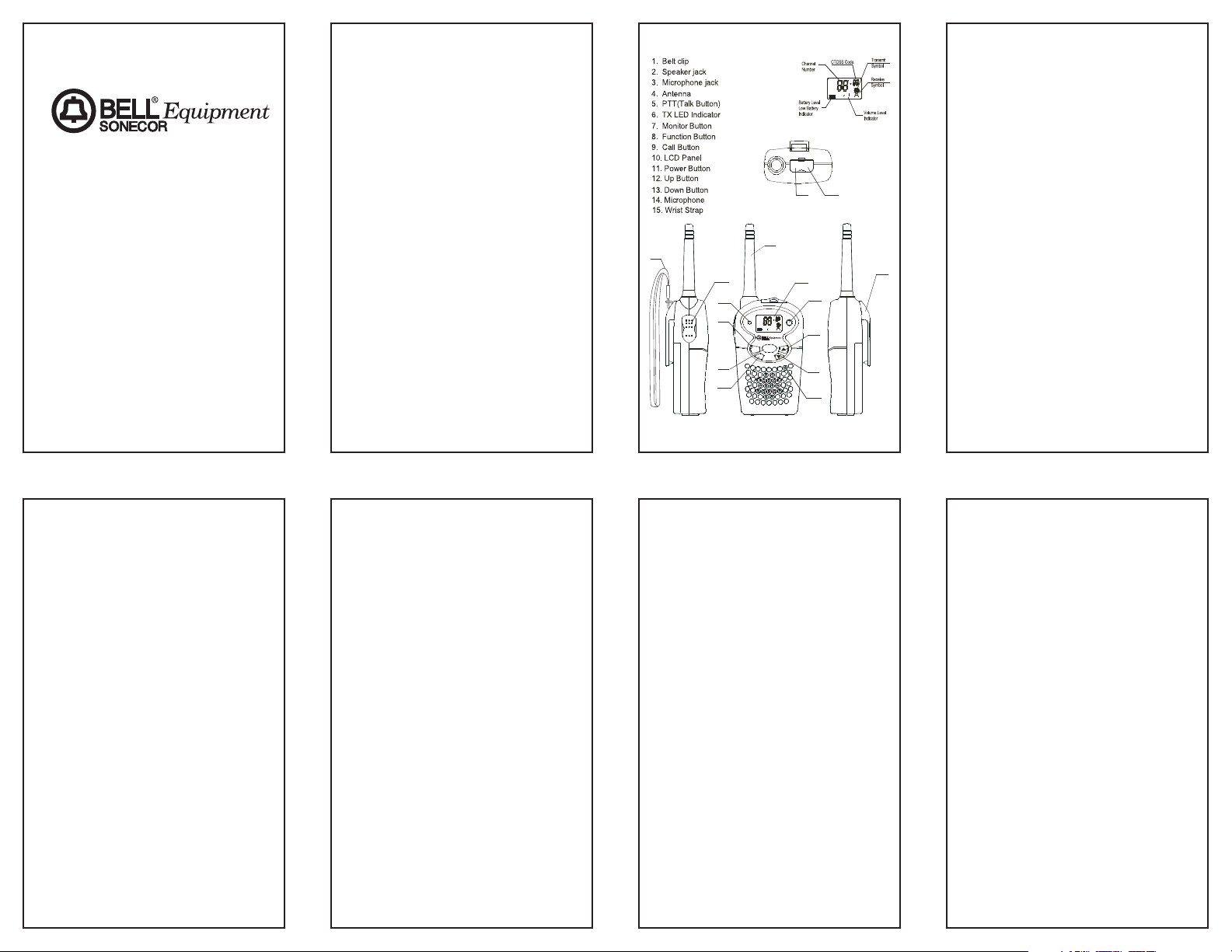
Radio Control Locations
DESCRIPTION
F (Function) Button - Allows you to
change channels and sub-codes.
C (CALL) Button – Sends a tone to
other radios that are tuned on the same
channel.
Battery Compartment - Houses four
“AAA” alkaline or rechargeable type
batteries.
Belt Clip - For your convenience, a belt
clip is included to secure the radio to a
belt or any other convenient location.
LCD (Liquid Crystal Display) Display A multi-functional display, which shows
channel, code and other radio
status/icons.
M (MONITOR) Button – Permits the
radio to continously monitor weak signals
and illuminates the LCD display to show
your current status.
MIC and SP. jacks – These jacks are
used to connect the optional
headset/microphone accessory.
PTT (Push To Talk) Button - Used for
making a call.
and Buttons - Used for changing
channels, codes, and setting the receive
volume.
POWER Button - Push and hold this
button to turn the BE-1438 radio on or off.
TX LED Indicator - This indicator lights
when transmitting a call.
Installation
BATTERY INSTALLATION
1. Prior to removing the battery cover,
make sure the belt clip is removed
(see section “Removing The Belt
Clip”).
2. Release the battery cover latch located on the rear side of the radio by
sliding it down.
3. Lift up the battery cover from the
battery compartment.
4. Install four “AAA” type batteries
(included); make sure to follow the
polarities marked inside the battery
compartment.
5. Reinstall the battery cover and the
belt clip.
Notes:
• The FRS has a built-in power saver
for maximum battery life while the
FRS is not in use.
• Remove the batteries if the unit will
not be used for a long period of time.
INSTALLING THE BELT CLIP
1. Slide the belt clip into the belt clip slot.
2. Make sure you hear a click to indicate
that the belt clip is securely in place.
REMOVING THE BELT CLIP
1. While pulling the belt clip tab, push up
on the belt clip to remove it from the
unit.
INSTALLING THE WRIST STRAP
1. While the belt clip is installed, insert
small loop of the wrist strap into the
small round hole located near the top
of the clip.
2. Make sure the loop runs up and out
2
1
Nylon Belt Pouch . . . . . . . . . . . . 5
Care and Safety . . . . . . . . . . . . .5-6
Maintenance . . . . . . . . . . . . . .5-6
Troubleshooting . . . . . . . . . . . . . . 6
FRS Channel Table . . . . . . . . . . . . 6
Limited Warranty . . . . . . . . . . . . . . 7
FCC Information
The FCC requires that you be advised of
certain requirements involving the use of
this device. This equipment has been
tested and found to comply with the limits
for a Class B digital device, pursuant to
Part 15 of the FCC Rules. These limits
are designed to provide reasonable
protection against harmful interference.
This equipment uses and can generate
radio frequency energy. If not used in
accordance with the instructions, it may
cause harmful interference to radio
communications. However, there is no
guarantee that the interference will not
occur in a particular use. If this equipment
does cause harmful interference to radio
or television reception (which can be
determined by turning the equipment off
and on), the user is encouraged to correct
the interference by one or more of the
following measures:
• Reorient or relocate the receiving
antenna.
• Increase the separation between the
equipment and receiver.
• Consult the manufacturer for technical
assistance.
Introduction
Congratulations on your purchase of the
BE-1438VP (Value Pack). These compact, lightweight radios and accessories
can be used at shopping malls, parks, or
while at the beach, hiking, biking, or
camping. You can talk to as many people
as you want, as often as you like, without
air time fees. It requires no license.
MODEL BE-1438VP
14 CHANNEL
38 SUB-CODE
FAMILY RADIO SERVICE
TRANSCEIVER
VALUE PACK
OWNER’S MANUAL
Please read this instruction manual
carefully.
Table of Contents
FCC Information . . . . . . . . . . . . . . 1
Introduction . . . . . . . . . . . . . . . . . 1
Radio Control Locations . . . . . . . 2
Descriptions . . . . . . . . . . . . . . . 2
Installation . . . . . . . . . . . . . . . . .2-3
Battery Installation . . . . . . . . . . 2
Installing the Belt Clip . . . . . . . . 2
Removing the Belt Clip . . . . . . . 2
Installing the Wrist Strap . . . . .2-3
Operation . . . . . . . . . . . . . . . . . . .3-4
Turning the Power On and Off . . 3
Adjusting the Speaker Volume . . 3
Receiving a Call . . . . . . . . . . . . 3
Transmitting a Call . . . . . . . . . . 3
Selecting Channels . . . . . . . . . . 3
Selecting the CTCSS Sub-Code
. . . . . . . . . . . . . . . . . . . . . . . .3-4
Monitor . . . . . . . . . . . . . . . . . . . 4
Battery Level/Low Battery
Indication . . . . . . . . . . . . . . . . . 4
Calling (paging) another radio . . 4
Value Pack Accessories . . . . . . .4-5
Headset . . . . . . . . . . . . . . . . . . . 4
Plug-in Battery Charger . . . . . .4-5
AAA Ni-Cd Batteries . . . . . . . . . 5
sp.
MIC
15
5
6
TX
7
PTT
M
9
8
2
3
4
10
11
POWER
12
C
F
13
14
1
Page 2

code selection and return to normal
mode.
Note: Refer to “FRS Channel Table”
CTCSS Code section of this
manual for detailed frequency
listings.
MONITOR
You can use the Monitor feature to listen
in for weak signals on the current channel.
For normal monitoring, press the
M
button.
For continuous monitoring:
1. Press and hold the
M button for at
least three seconds.
2. To deactivate continuous monitoring
press the
M button.
BATTERY LEVEL / LOW BATTERY
INDICATION
The LCD display shows the battery power
level according to the number of squares
inside the battery symbol.
When the battery level is low, the battery
icon will flash to indicate that the batteries
need to be changed.
Note: Due to the lower voltage of the
supplied NiCd batteries, the
indicator will never display as they
are fully charged. Rechargeable
batteries need to be charged more
often then you will need to replace
alkaline batteries, but in the long
run they are much more cost efficient.
CALLING (PAGING) ANOTHER
RADIO
To send a page:
1. Press and release the
C (Call) button
on the front of the radio. A page tone
will sound to every radio on that
frequency.
Note: In order for the paging feature to
work, both radios must be on.
Value Pack Accessories
HEADSET
The BE-1438 radio can be used with a
headset which has been
included in the value
pack for your convenience. Using a headset
eliminates the need to
use the built-in speaker
and microphone on the
radio. The BE-1438 contains a set of headset
jacks located at the top
of the unit for this purpose.
1. Lift the protective
rubber cover away
from the radio.
2. First insert the larger of the headset
plugs into the larger of the two jacks
on the BE-1438 radio.
3. Take care that the smaller of the
headset plugs fits correctly into the
smaller of the two jacks on the unit.
4. Place the headset on your head and
adjust the volume control on the radio
as required.
PLUG-IN BATTERY CHARGER
1. Pull down the adjustable contact plate
to fit the supplied AAA size Ni-Cd
rechargeable batteries.
2. Insert batteries with the polarities (+ -)
facing the indicated directions. Be
sure to insert the + end of the battery
first and then snap in the - end to
avoid causing damage to the lower
charging contacts.
4
Adjustable
contact plate
Front LED
Back LED
through the top of the belt clip.
3. Insert the large loop of the wrist strap
all the way through the small loop.
The strap should now be secure.
Operation
TURNING THE POWER ON AND OFF
Turning the Unit ON
1. Press and hold the POWER button.
The BE-1438 radio will emit a short
tone and the channel number will be
displayed on the LCD display.
Turning the Unit OFF
1. Press and hold the POWER button for
at least two seconds. The BE-1438
radio will emit a tone and the LCD
display will go blank.
ADJUSTING THE SPEAKER
VOLUME
• Press the button to increase the
volume.
• Press the
button to decrease the
volume.
RECEIVING A CALL
When your FRS unit is turned on and is
not being used to transmit voice communication or pages, the unit is continuously
set in receiving mode. When you receive a
call on the current channel you are using,
the LCD display will show the receive
icon.
TRANSMITTING A CALL
1. Press and hold the PTT button to
transmit. The TX LED will light up red
and the transmit icon will show in LCD
Display.
2. While holding the
PTT button, speak
in a normal voice approximately six
inches away from the microphone.
3. Release the
PTT button when you
have finished transmitting.
Note: In order to have two-way communi-
cation, all parties must be
transmitting on the same channel
and same sub-code. Refer to the
“Selecting Channels” and
“Selecting the CTCSS Sub-Code”
sections for more information.
SELECTING CHANNELS
The BE-1438 radio has 14 available channels. To change channels:
1. Press the
F (function) button. The
channel number flashes on the LCD
display.
2. While the channel number is flashing:
Press the button to increase the
channel number.
Press the
button to decrease the
channel number.
3. Press the
F button to confirm the
desired channel.
Note: Refer to the “FRS Channel Table”
section of this manual for detailed
frequency listings.
SELECTING THE CTCSS SUB-CODE
The BE-1438 radio has 38 available
CTCSS Sub-codes. Please set a CTCSS
Code in addition to a Channel if you do
not want to be bothered by other parties.
To set the CTCSS Code:
1. Press the
F button twice until the
CTCSS sub-code digits flash (or press
the
F button again when you are in
Channel Setting Mode).
2. While the CTCSS number is flashing:
Press the
button for a higher Code.
Press the
button for a lower Code.
3. Press the
F button or PTT button to
confirm your channel and CTCSS
3
TX
M
F
POWER
C
TX
Front
Back
Page 3

give years of trouble free service. To
assure longevity, please read the
following maintenance instructions.
1. To clean the radio, wipe with a soft
cloth dampened with water. Do not
use cleaners or solvents on the radio,
they can harm the body and leak
inside, causing permanent damage.
Battery contacts should be wiped with
a dry, lint free cloth.
2. If the radio gets wet, turn it off and
remove batteries, immediately. Dry
the battery compartment with a soft
cloth to minimize potential water
damage. Leave the cover off the
battery compartment overnight or
until completely dry. Do not use the
radio until completely dry.
3. In case of trouble with the BE-1438
radio, do not attempt to repair it yourself. It is the responsibility of users
requiring service to report the need
for service to our Service
Department. They will make the
necessary arrangements for repair or
replacement.
4. If you should have questions about
the operation of the BE-1438VP,
please call our Customer Service
Department at
1-888-663-1505.
You may also contact Aastra
Telecom for technical assistance
via our Internet Web site at
www.aastra.com
Troubleshooting
SYMPTOM SOLUTION
Does not turn on • Check that the
batteries are installed
properly.
• The batteries may be
weak. Replace old
batteries with four new
“AAA” batteries.
Reception is • Press the
button to
weak increase volume.
• The receiving signal
may be weak and out of
range. If this happens,
press the
M button.
Range is limited • Batteries may be weak.
Replace with new
batteries if the battery
level indicator is low.
• The maximum range
will vary depending on
terrain and
environment. Open
fields provide the
maximum range, while
buildings and other
structures may limit the
range significantly.
Sound distortion • If you are transmitting,
speak in a normal tone
of voice, approximately
six inches away from
the microphone.
• If you are receiving,
lower the volume
control to a comfortable
level.
6
Note: Batteries must be charged in pairs.
When charging only two batteries,
use the Front battery-charging
compartment.
3. Lock the wall plug into the out position
and plug it into an available wall jack.
The Front and/or Back LEDs will light
indicating the batteries are receiving
power.
4. Be sure to charge batteries for
approximately 7 hours to make sure
they are fully charged before use. Do
not overcharge.
Note: The charger has a built-in 15 hour
charge limit timer and will automatically turn off after that time has
passed.
Warning: This charger is intended for
use with Nickel-Cadmium
and Nickel-Metal-Hydride
rechargeable batteries only.
Attempting to charge other
types of batteries may
cause personal injury and
damage to the charger.
Caution:
1. Recharge only one type (Ni-Cd or Ni-
MH) of battery at each time.
2. Do not charge longer than the
specified time. Overcharging may
cause damage to the charger and
battery.
3. Do not expose charger to rain or mois-
ture. Intended for indoor use only.
4. Do not leave plugged into the wall jack
when it is not charging.
AAA Ni-Cd BATTERIES
8 AAA Ni-Cd batteries are included with
this value pack. They will function for
approximately 3.8 hours
talk (continuous) time or
2 days standby time in
the BE-1438 radios.
NYLON BELT POUCH
The nylon belt pouches which come with
BE-1438VP value pack are designed for
more flexible use of your radio. The belt
pouch allows you to have the BE-1438
radio handy without holding it in your
hand. The secure design allows for
attachment to your belt, or lets you hang
the radio from around your neck if you use
a chain or strap (not
provided) while still being
able to access the front
panel. In the belt pouch,
the radio is more secure
and is easier to remove
and replace at your
leisure.
Care and Safety
Caution: Do not operate the BE-1438
radio at high audio volume levels when
using it with a headset. Hearing experts
advise against continuous high volume
operation. If you experience a ringing in
your ears, turn off the radio before plugging in the headset.
Warning: Do not operate this radio in
hazardous environments. Explosion or
fire may result.
Do not operate this radio near unshielded
electrical blasting caps.
Under certain conditions, radios can interfere with blasting operations and may
cause an explosion. Construction crews
often use remote control RF devices to
set off explosives.
IMPORTANT: Turn off your radio to prevent accidental transmission when in a
"blasting area" or in areas posted: "Turn
off two way radio”.
MAINTENANCE
The BE-1438 radio has been designed to
5
TX
Page 4

600-0540201-A
Limited Warranty
Aastra Telecom
A. Aastra warrants that the BE-1438VP
sold by Aastra within the continental
limits of the United States, Hawaii and
Alaska, is free from defects in
materials and workmanship under
normal use and service for 1 year.
This warranty is applicable only to the
original purchaser of the BE-1438VP,
when accompanied by a sales receipt
stating the date of purchase and
name of the company from which
purchased. This warranty is in lieu of
and excludes all other warranties,
expressed or implied, including any
implied warranty of merchantability or
fitness, and of any other obligation on
the part of Aastra.
B. If the BE-1438VP shall prove to be
defective, then Aastra shall either
replace or repair the BE-1438VP at its
discretion. Warranty service for
your BE-1438VP is provided by
Aastra Telecom.
For Warranty Service
Please Call 888-663-1505
C. You will be responsible for shipping
charges, if any. When you return
this telephone for warranty service,
you must present proof of purchase
D. There is no informal dispute settle-
ment mechanism available.
E. Some states do not allow limitations
on how long an implied warranty lasts
and/or do not allow the exclusions or
limitations of incidental or
consequential damages, so the above
limitations or exclusions may not apply
to you.
F. This warranty gives you specific legal
rights, and you may also have other
rights which vary from state to state.
G. This warranty does not extend to any
BE-1438VP sold by Aastra which has
been subjected to misuse, neglect,
accident, improper application,
improper installation or to use in violation of the instructions furnished by
Aastra. This warranty does not extend
to or apply to any BE-1438VP which
has been repaired or altered by any
persons who have not been expressly
approved by Aastra.
H. Aastra shall not be liable for any
special or consequential damages or
for loss or expense directly or indirectly arising from use of the products or
any inability to use them either separately or in combination with other
equipment or product accessories or
from any other cause.
I. Aastra reserves the right to make
changes in the design of the BE1438VP and to make additions or
improvements to the BE-1438VP with-
out incurring any obligation to modify
any BE-1438VP previously sold.
7
 Loading...