

Page 1
Introduction
Congratulations on your purchase of
the BE-1438SP (Super Pack). These
compact, lightweight radios and accessories can be used at malls, parks,
while at the beach, hiking, biking, or
camping. You can talk to as many
people as you want, as often as you
like, without air time feesor a license.
Radio Control Locations
DESCRIPTION
Battery compartment - Houses four
“AAA” alkaline or rechargeable type
batteries.
Belt-clip - For your convenience, a
belt-clip is included to secure the radio
to a belt or any other similar location.
CALL button – Sends a tone to other
radios tuned to that channel and code.
Ear/Mic. jack – This jack is used to
connect a 3.5 mm stereo headset/mic.
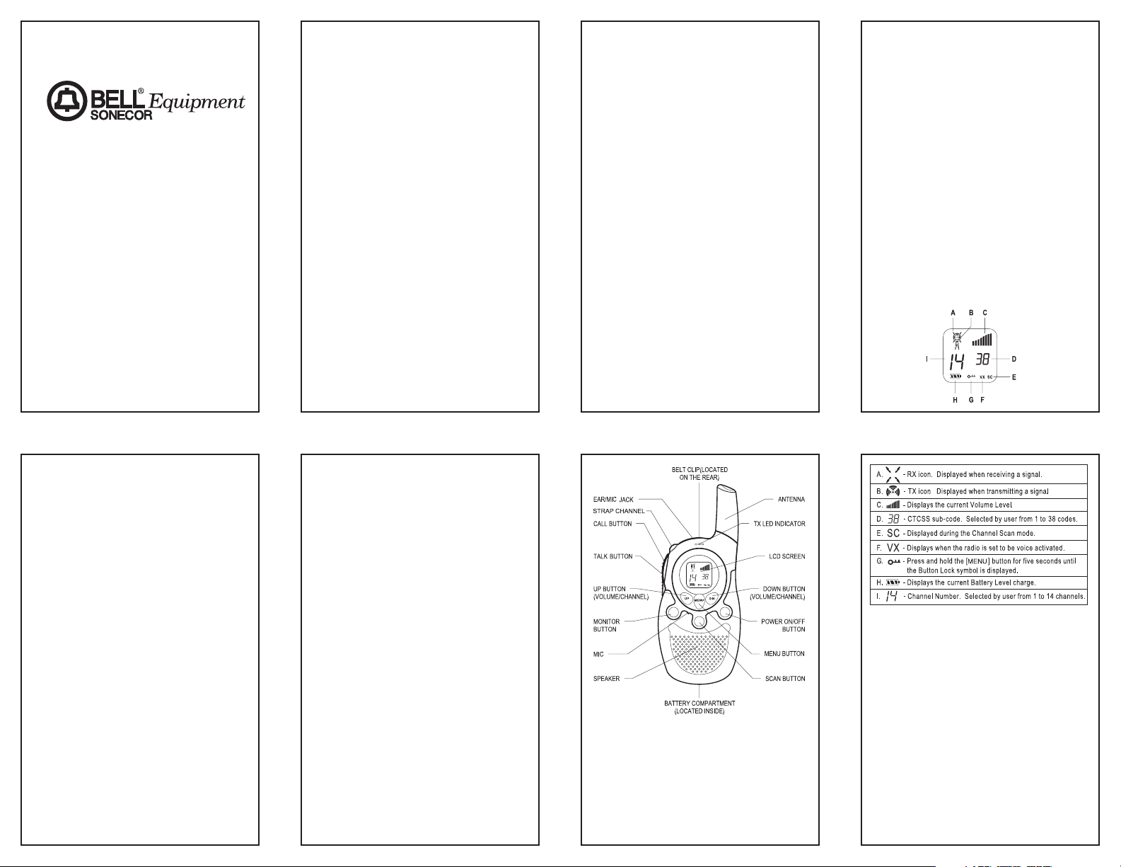
LCD (Liquid Crystal Display) - A
multi-functional display, which shows
channel, code and other radio
status/icons (see specifics below).
MENU/Lock button - Allows you to
change channels and sub-codes.
Press and hold for five seconds to lock
or unlock the buttons on the radio face.
MONITOR button – Permits the radio
to continously monitor weak signals
and illuminates the LCD display to
show your current status.
TALK button - Used for making a call.
POWER button - Push and hold this
button to turn the unit on or off.
SCAN button - Used to activate and
deactivate channel scanning.
TX LED Indicator - This indicator
lights when the radio is transmitting.
UP and DN buttons - Used for
changing channels, codes, and setting
the receive volume.
Installation
BATTERY INSTALLATION
1. Prior to removing the battery cover,
make sure the belt-clip is removed
(see “Removing The Belt-clip”).
2. Release the battery cover catch
located on the rear side of the radio
by pushing on the tab.
3. Lift up the battery cover from the
battery compartment.
4. Install four “AAA” type alkaline
batteries (included) or rechargeable
2
1
Calling (paging) another
radio . . . . . . . . . . . . . . . . . . . 5
Using the VOX feature . . . . . . 5
Super Pack Accessories . . . . .5-6
Headset . . . . . . . . . . . . . . . . . 5
AAA Alkaline Batteries . . . . . 5
Nylon Belt Pouch . . . . . . . .5-6
Travel Pack . . . . . . . . . . . . . . 6
Water Resistant Pouch . . . . . 6
Care and Safety . . . . . . . . . . .6-7
Maintenance . . . . . . . . . . . .6-7
Specifications . . . . . . . . . . . . . . 7
FRS Channel Table . . . . . . . . . . 7
Troubleshooting . . . . . . . . . . . . 7
Limited Warranty . . . . . . . . . . . . 8
FCC Information
This device complies with Part 15 of
the FCC rules. Operation is subject to
the following two conditions:
1. This device may cause harmful
interference, and
2. This device must accept any
interference received, including
interference that may cause undesired operation.
Warning: Modifying or tampering with
the radio’s internal components can
cause a malfunction and may cause a
violation of the technical regulations of
part 95 of the FCC Rules, or violation
of Type Acceptance requirements of
Part 2 of the Rules. This may invalidate the radio’s warranty and void your
FCC authorization to operate it.
MODEL BE-1438SP
14 CHANNEL
38 SUB-CODE
FAMILY RADIO SERVICE
TRANSCEIVER
SUPER VALUE PACK
OWNER’S MANUAL
Please read this instruction manual
carefully.
Table of Contents
FCC Information . . . . . . . . . . . . 1
Introduction . . . . . . . . . . . . . . . 2
Radio Control Locations . . . . . 2
Descriptions . . . . . . . . . . . . . 2
Installation . . . . . . . . . . . . . . .2-3
Battery Installation . . . . . . .2-3
Installing the Wrist Strap . . . . 3
Installing the Belt Clip . . . . . . 3
Removing the Belt Clip . . . . . 3
Operation . . . . . . . . . . . . . . . . .3-5
Turning the Power On
and Off . . . . . . . . . . . . . . . . . 3
Adjusting the Speaker
Volume . . . . . . . . . . . . . . . . . 3
Receiving a Call . . . . . . . . . . 3
Transmitting a Call . . . . . . . . 4
Selecting Channels . . . . . . . . 4
Selecting the CTCSS
Sub-Code . . . . . . . . . . . . . . . 4
Scanning Channels . . . . . . . . 4
Monitor . . . . . . . . . . . . . . . .4-5
Battery Level/Low Battery
Indication . . . . . . . . . . . . . . . 5
a
y
W
-
R
2
a
d
S
i
R
o
F
MONITOR
POWER
SCAN
Page 2
TRANSMITTING A CALL
1. Press and hold the TALK button to
transmit. The TX LED will light up
red and the transmit icon will show
in LCD Display.
2. While holding the
TALK button,
speak in a normal voice approximately six inches away from the
microphone.
3. Release the
TALK button when you
have finished transmitting.
Note: In order to have two-way com-
munication, all parties must
transmit on the same channel
and sub-code. Refer to the
“Selecting Channels” and
“Selecting the CTCSS SubCode” sections for more
information.
SELECTING CHANNELS
The BE-1438SP radios have 14 available channels. To change channels:
1. Press the
MENU button. The
channel number flashes on the
LCD display.
2. While the channel number is
flashing:
Press the
UP button to increase
the channel number.
Press the
DN button to decrease
the channel number.
3. Press the
MENU button to confirm
the desired channel and move to
sub-code programming, or press
TALK to save and return to normal
mode.
Note: Refer to the “FRS Channel
Ta bl e ” section of this manual
for detailed frequency listings.
SELECTING THE CTCSS SUBCODE
The BE-1438SP radios have 38 available CTCSS Sub-codes. Please set a
CTCSS Code in addition to a Channel
if you do not want to be bothered by
other parties. To set the CTCSS Code:
1. Press the MENU button twice until
the CTCSS sub-code digits flash
(or press the MENU button again
when you are in Channel Setting
Mode).
2. While the CTCSS number is
flashing:
Press the
UP button for a higher
Code.
Press the
DN button for a lower
Code.
3. Press the
MENU button or TALK
button to confirm your channel and
CTCSS code selection and return
to normal mode.
Note: Refer to “FRS Channel Table”
CTCSS Code section of this
manual for detailed frequency
listings.
SCANNING CHANNELS
It is possible to scan the channels for
one which is being actively used by
using the following procedure:
1. Press the SCAN button to activate.
The radio will scan rapidly through
the 14 channels until an active
channel is found.
2. When an active signal is detected,
the radio pauses at that channel to
broadcast the signal.
3. Press
TALK to communicate
through the active channel and
leave Scan mode.
3. When an active channel is found
but you wish to continue scanning,
press
UP or DN to bypass the
current channel.
4. To deactivate scanning press the
SCAN button again.
If the radio scans all channels without
finding an active one, it will continue to
loop unless some button is pressed to
stop it.
MONITOR
You can use the Monitor feature to
listen in for weak signals on the current
4
“AAA” type batteries (not included);
make sure to follow the polarities
marked inside the battery
compartment.
5. Reinstall the battery cover and the
belt-clip.
Note: Remove the batteries if the unit
will not be used for a long
period of time.
INSTALLING THE WRIST STRAP
1. Insert small loop of the wrist strap
into the small round hole located on
the top of the radio between the
headset jack and the
CALL button.
2. Make sure the loop runs up and out
through the top of the belt-clip.
3. Insert the large loop of the wrist
strap all the way through the small
loop. The strap should now be
secure.
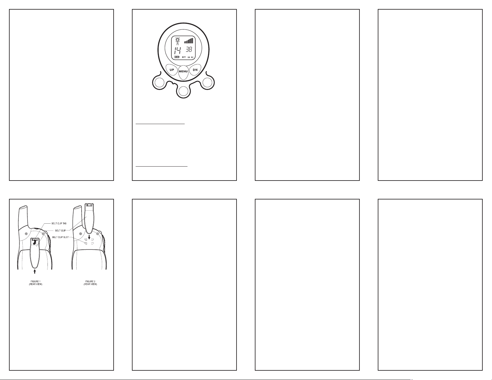
INSTALLING THE BELT-CLIP
1. Insert the belt-clip hooks into the
matching slots as shown above
(Figure 1).
2. Slide the belt-clip down. A click
indicates the Belt-clip is locked into
position (Figure 2).
REMOVING THE BELT-CLIP
1. Push up on the belt-clip while
squeezing the belt-clip tab.
Operation
TURNING THE POWER ON AND OFF
Turning the Unit ON
1. Press and hold the POWER button.
The BE-1438SP radios will emit a
short tone and the LCD screen will
display
FrS and then the current
channel.
T
urning the Unit OFF
1. Press and hold the POWER button
for at least two seconds. The BE1438SP radios will emit a tone and
the LCD display will go blank.
ADJUSTING THE SPEAKER
VOLUME
• Press the UP button to increase the
volume.
• Press the
DN button to decrease
the volume.
The speaker volume level is indicated
by the number of bars displayed in the
upper right corner of the LCD.
RECEIVING A CALL
When your FRS unit is turned on and
is not being used to transmit voice
communication or pages, the unit is
continuously set in receiving mode.
When you receive a call on the current
channel you are using, the LCD display
will show the receive icon.
3
a
y
W
-
R
2
a
SCAN
d
i
o
POWER
S
R
F
MONITOR
Page 3

NYLON BELT POUCH
The nylon belt pouches
which come with BE1438SP super pack are
designed for more
flexible use of your radio.
It is recommended that
you remove the belt-clip
from the radio before
inserting it into the belt
pouch.
The belt pouch allows you to have the
BE-1438SP radios handy without
holding them in your hand. The
secure design allows for attachment to
your belt, or lets you hang the radio
from around your neck if you use a
chain or strap (not provided) while still
being able to access the front panel.
In the belt pouch, the radio is more
secure and is easier to remove and
replace at your leisure.
TRAVEL PACK
To easily carry the FRS radios, accessories, and possibly even a picnic
lunch, use the included travel pouch,
designed to attach snuggly around
your waist.
WATER RESISTANT POUCH
To protect your radio from moisture,
place the radio in the water resistent
ziplock pouch that was designed
specially to fit the BE-1438SP radios.
The radios work through the pouches.
Care and Safety
Caution: Do not operate the BE-
1438SP radios at high audio volume
levels when using it with a headset.
Hearing experts advise against continuous high volume operation. If you
experience a ringing in your ears, turn
off the radio.
Warning: Do not operate this radio
in hazardous environments.
Explosion or fire may result.
Do not operate this radio near
unshielded electrical blasting caps.
Under certain conditions, radios can
interfere with blasting operations and
may cause an explosion. Construction
crews often use remote control RF
devices to set off explosives.
IMPORTANT: Turn off your radio to
prevent accidental transmission when
in a "blasting area" or in areas posted:
"Turn off two way radio”.
MAINTENANCE
The BE-1438SP radios have been
designed to give years of trouble-free
service. To assure longevity, please
read the following maintenance
instructions.
1. To clean the radio, wipe with a soft
cloth dampened with water. Do not
use cleaners or solvents on the
radio, they can harm the body and
leak inside, causing permanent
damage. Battery contacts should
be wiped with a dry, lint free cloth.
2. If the radio gets wet, turn it off and
remove batteries, immediately. Dry
the battery compartment with a soft
cloth to minimize potential water
damage. Leave the cover off the
battery compartment overnight or
until completely dry. Do not use the
radio until completely dry.
3. In case of trouble with the BE1438SP radios, do not attempt to
repair them yourself. It is the
responsibility of users requiring
service to report the need for
service to our Service Department.
They will make the necessary
arrangements for repair or replacement.
4. If you should have questions about
the operation of the BE-1438SP
components, please call our
Customer Service Department at
1-
800-276-5844
. You may also
6
channel.
For normal monitoring, press the
MONITOR button.
For continuous monitoring:
1. Press and hold the
MONITOR
button for at least three seconds.
2. To deactivate continuous monitoring press the
MONITOR button.
BATTERY LEVEL / LOW BATTERY
INDICATION
The LCD display shows the battery
power level according to the number of
squares inside the battery symbol.
When the battery level is low, the
battery icon will flash to indicate that
the batteries need to be changed.
CALLING (PAGING) ANOTHER
RADIO
Call tones are used to request other
people on the same channel to identify
themselves or signal the beginning or
end of a conversation. To send a page:
1. Press and release the CALL button
on the left side of the radio. A page
tone will sound to every radio on
that frequency.
Note: In order for the paging feature
to work, both radios must be on.
USING THE VOX FEATURE
The BE-1438SP radios are capable of
voice activated (VOX) transmission.
When this setting is on, you do not
need to press the
TALK button to
transmit- transmission begins when
any sound is heard near the
microphone.
1. Press the
MENU button until “VX”
and “oF” are displayed on the LCD.
2. Press
UP to activate the VOX
feature. The “oF” will change to
“On.”
3. Press
MENU or TA LK to return to
normal mode.
4. When in VOX mode, the “VX” icon
will display on the LCD screen.
5. To turn off voice activation, follow
the same procedure only press the
DN button to change the “On” to
“oF” (Off).
Note: VOX sensitivity is purposely set
low so that extraneous noises
are not picked up and transmitted. While in VOX mode, be
sure to speak clearly and
directly into the microphone,
whether using a headset or not.
Super Pack Accessories
HEADSET
The BE-1438SP radios can be used
with a headset which has been
included in the super pack for your
convenience. Using a headset
eliminates the need to use the built-in
speaker and microphone on the radio.
The BE-1438SP radios contain a
headset jack located at the top of the
unit for this purpose.
1. Lift the protective
rubber cover away
from the radio.
2. Insert the the
headset plug into the
jack on the BE1438SP radios.
3. Take care that the
headset plug fits
correctly into the jack
on the unit.
4. Place the headset on your head
and adjust the volume control on
the radio as required.
AAA ALKALINE BATTERIES
Eight AAA Alkaline
batteries are included
with this super pack.
They will function for
approximately 4 hours talk (continuous)
time or 3 days standby time in the BE1438SP radios.
5
a
y
W
-
R
2
a
d
S
i
R
o
F
MONITOR
POWER
SCAN
Page 4

contact TT Systems LLC for technical assistance via our Internet Website at www.ttsystems.com.
5. Please register your product online
at:
www.ttsystems.com/CustomerSupport/RegOnline.asp
Specifications
FRS Channel Table
Troubleshooting
SYMPTOM SOLUTION
Does not turn on • Check that the batteries
are installed properly.
• The batteries may be
weak. Replace old
batteries with four new
“AAA” batteries.
Reception is • Press the
UP button
weak to increase volume.
• The receiving signal
may be weak and out of
range. If this happens,
press the
MONITOR
button.
Range is limited • Batteries may be weak.
Replace with new
batteries if the battery
level indicator is low.
• The maximum range
will vary depending on
terrain and
environment. Open
fields provide the
maximum range, while
buildings and other
structures may limit the
range significantly.
Sound distortion • If you are transmitting,
speak in a normal tone
of voice, approximately
six inches away from
the microphone.
• If you are receiving,
lower the volume
control to a comfortable
level.
7
Channels Available 14 Channels
CTCSS Sub-Channel 38 for each Channel
Output Power (TX) .05W (FCC
Maximum
Battery Life 30 Hours (typical)
Range Up to 2 miles
8
600-0780901-B
 Loading...