

Page 1
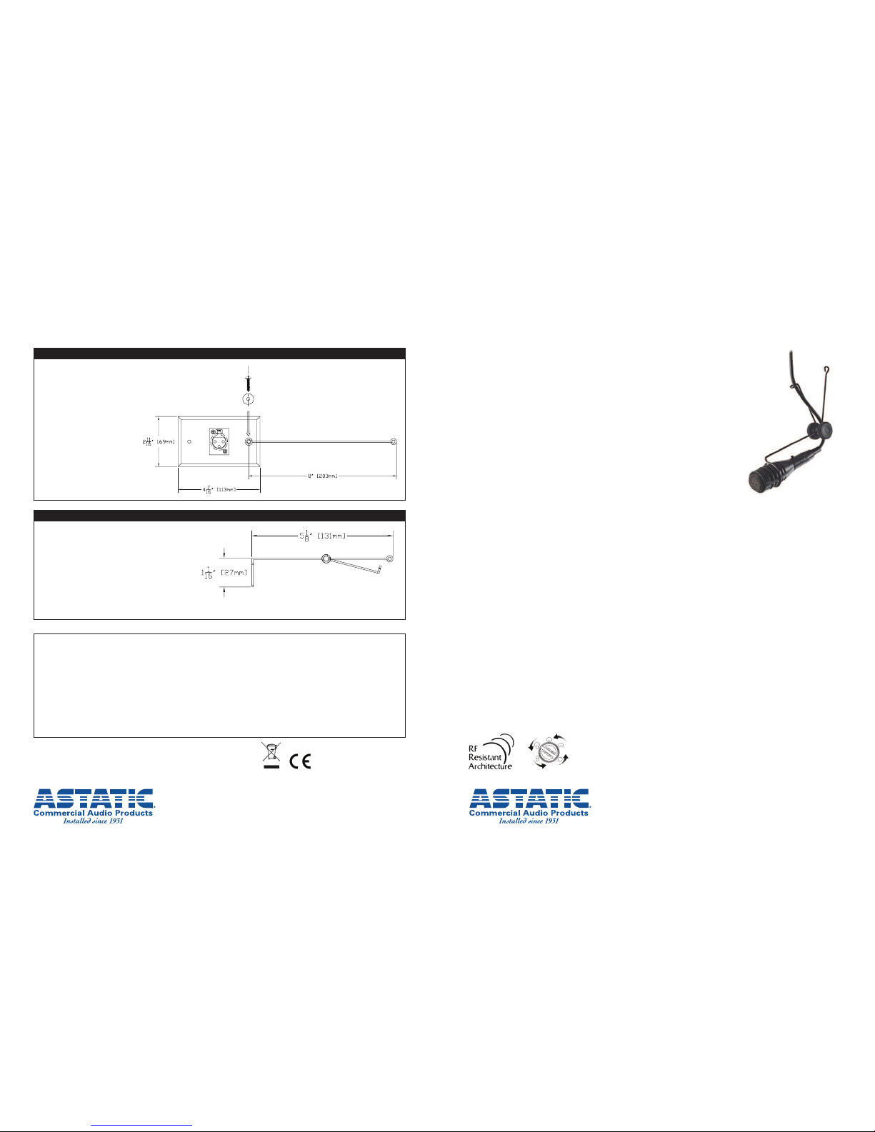
1600VP
Continuously-variable Pattern Condenser Hanging Microphone System with Remote Polar
Control and Exclusive Anti-rotational Positioning Mount
Description
T
he 1600VP is a continuously-variable pattern condenser hanging microphone
system with remote polar control and anti-rotational positioning mount. The
variable polar pattern with remote control allows the user to precisely adjust
the shape of the pick-up pattern for best performance from a remote location.
Utilizing a t wo-conductor shielded cable (max length 2,000 feet) bet ween the
microphone head and the pattern-control box, the user can adjust the polar
pattern in real time without changing capsules, microphone positions, or
inducing noise in the audio chain.
Special attention has been given to the frequency response and sensitivity of
the microphone while utilizing the variable-pattern control to precisely alter the
shape of the pick-up pattern. The large-diameter, low-noise elements produce
a frequency response of 40Hz to 20KHz with a selectable, recessed 80Hz,
12dB/octave high-pass filter that removes unwanted low-frequency energy
when engaged. The filter control is conveniently located on the control box.
The microphone head is made of commercial grade aluminum, the control box
is made of hardened steel, both are powder coated and made in the USA. The
microphone head is painted matte black for an unobtrusive yet stylish appearance. The remote polar-pattern control box can be mounted in a single rack unit shelf with optional accessories.
Up to six control boxes can be mounted in one rack unit - Astatic RU1. The polar-pattern dial is positioned for easy
adjustment ”on the fly” and can be secured with a single “Flat Style” blank panel when rack mounted.
The 1600VP has been designed to resist interference from devices such as cell phones, two-way communication
devices and lighting apparatus. Utilizing our RF Resistant Architecture, the 1600VP meets the stringent RF st andards
set by the European Union (see the specification section for more information).
The 1600VP comes complete with 30' (9.1m) of two-conductor shielded cable terminated with aTA3F-type connector
and 3-pin XLRM-t ype connector. Also included with the microphone system is a 3-pin XLRF-type connector on a stainless steel duplex wall plate, exclusive articulating steel hanger, and anti-t wist thread and rods.
The 1600VP is primarily designed for recording and sound reinforcement of choirs, instruments and ambient miking.
The 1600VP can also be used for vocal pick-up in government, institutional and business applications. The 1600VP is
designed to be suspended from a ceiling. The optional miniature-boom (MB-1), allows the microphone system to be
used on a free-standing microphone post.
The 1600VP microphone system is designed to shorten the list of products an audio designer needs to consider when
hanging microphones are specified. The remote variable polar pattern control allows the installer or end user the ability
to change polar patterns when installed or from scene to scene. Adjustments to the pick-up pattern can be done ”on
the fly“ without costly lifts, ladders and capsules. Choose the 1600VP for your next overhead microphone install.
Features
• Continuously-variable polar pattern controllable from a remote location
• Remote box is rack mountable, up to six units per shelf
• Blue LED status indicator on remote box
• Selectable recessed high-pass filter for elimination of unwanted low-frequency energy
• Securable controls with standard flat style blank rack panel, when rack mounted
• RF (radio frequency) Resistant Architecture
• Included 30’ (9.1m) cable, wall plate, articulating steel hanger and all accessories for hanging the microphone
Astatic Commercial Audio Products
6573 Cochran Rd. Building I Solon, Ohio 44139 U.S.A.
Tel: (440) 349-4900 Fax: (440) 248 -4902 Sales: (800) 421-3161
www.astaticinstalled.com
©2009 AstaticCommercial AudioProducts
Part No.46873 -92-00Apr2009
Two-Year Limited Warranty
Astatic CommercialAudio Productshereby warrantsthat this productwill befree of defectsin materialand workmanshipfor aperiod of twoyears fromthe date ofpurchase. Inthe unlikely
event thata defectoccurs Astaticwill, at itsoption, eitherrepair or replacewith anew unit ofequal orgreater value. Retainproof ofpurchase tovalidate thepurchase dateand return itwith
any warrantyclaim.
This warrantyexcludes exteriorfinish orappearance, damage fromabuse, misuseof the product,use contrary toAstatic’s instructions orunauthorized repair.All impliedwarranties,
merchantability,or fitness fora particularpurpose is herebydisclaimed andAstatic herebydisclaims liability forincidental, specialor consequential damagesresulting fromthe use or
unavailability ofthis product.
This warrantygives youspecific legal rightsand youmay haveother rightsthat vary fromstate to state.Some states donot allowthe exclusionor limitation ofincidental orconsequential
damages orlimitations on howlong animplied warranty lasts,so theabove exclusionsand limitations maynot applyto you.
Note: Noother warranty,written ororal is authorizedby AstaticCommercial AudioProducts.
Shipping Instructions
Please callour customer servicedepartment at 440-349-4900for apre-approved returnauthorization number.
Carefully repackthe unitand return theinsured packageto: AstaticCommercial AudioProducts, 6573Cochran Road,Building I, Solon,Ohio 44139. RETURNSWITHOUT A
PRE-APPROVED RETURNAUTHORIZATION NUMBERWILL BE REFUSED.
If outsidethe United States,contact yourlocal dealer ordistributor forwarranty details.
4 of 4 1 of 4
U
sing the Wall Plate
1. Attach the upper-support arm
t
o the wall plate.
2. Run provided thread to
counterbalance support
(small loop on support).
3. The microphone head can be
twisted in the hanger to help
correct for rotation if the
thread is not used.
Using the Articulating Steel Hanger
1. Insert the microphone head into the large
hoop of the hanger.
2. Line up the microphone head screw hole
and insert security screw.
3. Run the provided cable through the hanging
hoop (small hoop).
4. Wrap the cable around the underside of the
pivot joint.
5. Adjust microphone angle and tighten
thumb screw.
Page 2
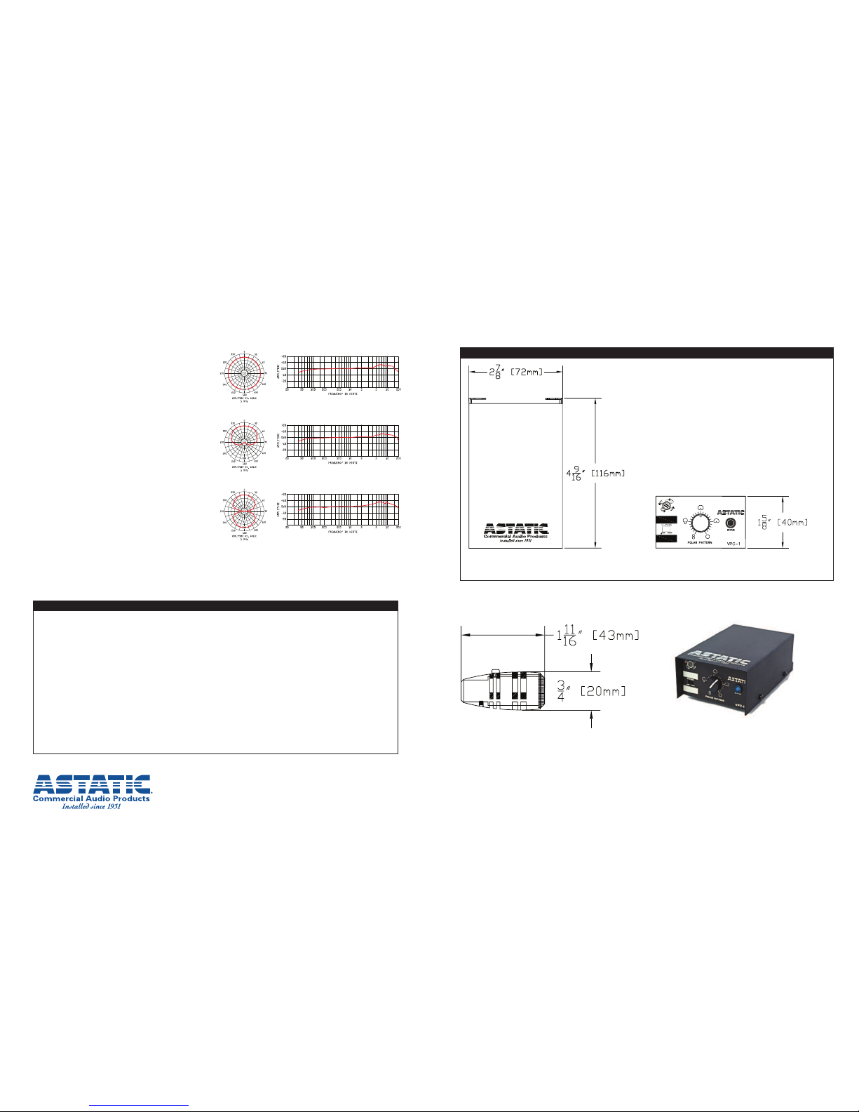
Specifications
†
Operating Principle..............................................Condenser
Polar Pattern........................................Continuously-variable
F
requency Response ......................................40Hz - 20KHz
Sensitivity ..........................................-29dBV (35mV) @ 1Pa
Impedance ............................................................135 ohms
S
elf Noise....................................................................22dBA
Maximum SPL ..................................110dB, 1% THD, 1KHz
Power Requirements............................P12, P24, P48, 4mA
C
onnector ..................................................3-pin XLRM-type
Polarity ................................Positive pressure on diaphragm
corresponds to positive voltage on pin 2
relative to pin 3 at XLRM-t ype connector.
Finish ..................................................................Matte-black
Dimensions......................................................(See drawing)
Net Weight Mic Head [Mass] ........................1.1oz [0.03Kg]
Net Weight Control Box [Mass] ....................12oz [0.34Kg]
PackagedWeight [Mass] ..........................1lb 14oz [0.85Kg]
RF Immunity ........................Meets or exceeds EN5510 3 -2,
E1, E2, E3 and E4
RoHS Compliant
†
S
pecifications subjectto change without notice.
Included Accessories....................................40-347, 40-354,
Articulating Steel Hanger.
Optional Accessories ........................................MB-1, RU-1.
The microphone will be an overhead-condenser type
designed to be suspended or mounted on a boom
(Astatic MB-1). The microphone will have a continuouslyvariable polar pattern controllable from the remote-control
box connected by a two conductor shielded cable. The
sensitivity of the microphone will be –29dBV (35mv) @
1Pa. The frequency response will be 40Hz - 20KHz. The
impedance of the microphone will be 135 ohms. The self
noise will be 22dBA. The maximum SPL will be 110dB.The
microphone will include a selectable 80Hz, 12dB/octave
high-pass filter controllable on the remote control box for
increased intelligibility.
The microphone will have a TB3M-type connector on the
rear of the microphone element enclosure. The control
box will have 3-pin XLRF-type input and 3-pin XLRM-type
signal output. The microphone will operate on P12, P24 or
P48 standard phantom power consuming 4mA. The micro-
phone element and electronics will be enclosed in radio
frequency resistant housings meeting or exceeding
EN55103-2.The microphone element enclosure will be
1-11/16" [43mm] long, 3/4" [20mm] in diameter. The net
weight [mass] will be 1.1oz [0.03Kg] not including the
cable. The microphone remote polar pattern control
enclosure will be 4-9/16" [116mm] long, 2-7/8" [72mm]
wide and 1-5/8" [40mm] high. The net weight [mass] will be
12oz [0.34Kg] not including the cable. The packaged weight
[mass] will be 1lb 14oz [0.85Kg]. The 1600VP will have a
durable matte-black finish.
The Astatic model 1600VP is specified.
Omnidirectional
Cardioid
Figure-of-eight
Astatic Commercial Audio Products
6573 Cochran Rd. Building I Solon, Ohio 44139 U.S.A.
Tel: (440) 349-4900 Fax: (440) 248 -4902 Sales: (800) 421-3161
www.astaticinstalled.com
1600VP
Continuously-variable Pattern Condenser Hanging Microphone System with Remote Polar
Control and Exclusive Anti-rotational Positioning Mount
2 of 4 3 of 4
T
he connection cable between the microphone element enclosure
and the control box is to be two conductors, with a braided shieldcable. (Existing microphone wiring, such as mic cable or anAnalog
A
udio snake can be used).
1. Connect the microphone head to theTA3F-type connector
of the cable provided.
2. The Female Plug on the control box will accept the 3-pin
XLRM-type cable from the microphone element enclosure.
3. Connect the 3-pin XLRM-t ype to an audio mixer or recording
providing phantom power (P12, P24, P48).
4. When all connections are made and phantom power is applied
the Blue LED on the control box will illuminate to indicate
proper connection to the mic head.
5. Adjust the polar pattern as desired.
6. Use the white spaces to label the control box.
Final Connections
Architects’ and Engineers’ Specification
VPC-1 Variable-pattern Control BoxTop View
Microphone Head VPC-1 Variable-pattern Control Box
 Loading...