

Page 1
802.11n Wireless 2T2R Router
R4020A
Advanced User Manual
Version 0.1
Date: January 14, 2013
0
Page 2

Contents
Overview ........................................................................................................................ 3
About this Product ................................................................................................. 3
Key Features ........................................................................................................... 3
What’s in the Box? ......................................................................................................... 4
Package Contents ................................................................................................... 4
LED Indicators ......................................................................................................... 4
Panel ....................................................................................................................... 5
To Be Started .................................................................................................................. 6
System Requirements ............................................................................................ 6
Connecting the Router ........................................................................................... 6
Operation Mode ............................................................................................. 6
Power on the Router ...................................................................................... 8
Quick Setup Wizard ........................................................................................................ 9
Login to the Web Management Interface .............................................................. 9
Setup Wizard for Gateway Mode (Router Mode) ................................................ 10
Setup Wizard for Bridge Mode (AP Mode) .......................................................... 14
Wireless Settings .......................................................................................................... 18
Basic Settings ....................................................................................................... 18
Advanced Settings ................................................................................................ 22
Security ................................................................................................................ 24
Access Control ...................................................................................................... 38
Site Survey ............................................................................................................ 39
WPS ...................................................................................................................... 42
Schedule ............................................................................................................... 44
TCP/IP ........................................................................................................................... 45
LAN Interface ....................................................................................................... 45
WAN Interface ...................................................................................................... 49
Firewall ......................................................................................................................... 57
Port Filtering ........................................................................................................ 57
IP Filtering ............................................................................................................ 58
MAC Filtering ....................................................................................................... 59
Port Forwarding ................................................................................................... 60
URL Filtering ......................................................................................................... 61
DMZ ...................................................................................................................... 62
VLAN ..................................................................................................................... 63
QoS ............................................................................................................................... 64
Management ................................................................................................................ 66
1
Page 3

Status .................................................................................................................... 66
Statistics ............................................................................................................... 67
DDNS .................................................................................................................... 68
Time Zone Setting ................................................................................................ 69
Denial-of-Service .................................................................................................. 70
Log ........................................................................................................................ 71
Upgrade Firmware ............................................................................................... 72
Save/Reload Settings ............................................................................................ 73
Password .............................................................................................................. 74
Logout .......................................................................................................................... 75
Troubleshooting ........................................................................................................... 76
Specifications ............................................................................................................... 77
Glossary ........................................................................................................................ 78
Appendix A: TCP/IP Settings ......................................................................................... 80
2
Page 4

Overview
About this Product
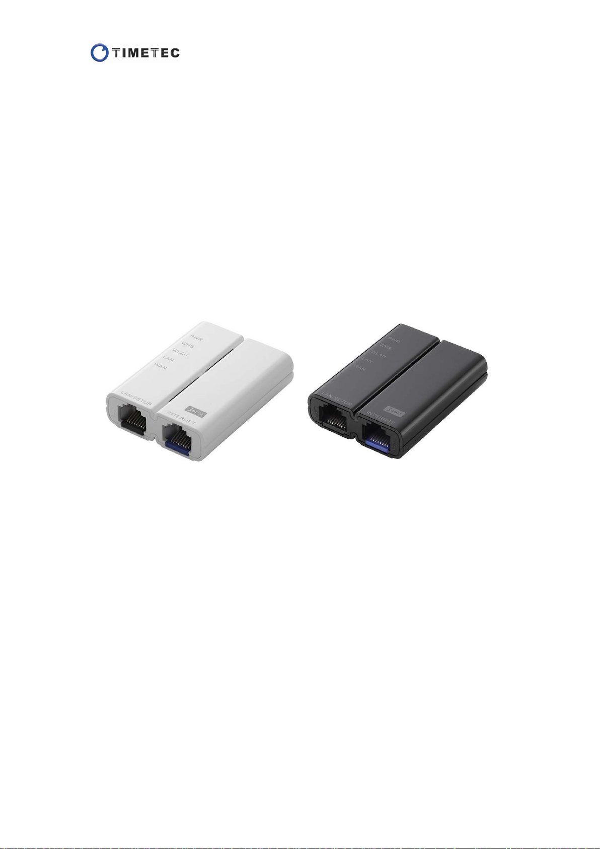
This is a wireless router with 2T2R MIMO technology providing an excellent network
solution for home, SOHO and hotspot users. It complies with standards IEEE 802.11n
with data rate up to 300 Mbps, and IEEE 802.11b/g with maximum data rate of 54
Mbps. It can also interoperate with all the 11/54 Mbps wireless (802.11b/g) products.
The router allows multiple users to share one broadband connection, as well as
secures your private network. With its built-in two ports switch and wireless AP, LAN
users can share files, printers, or playing network games.
To provide a secure wireless network, this router supports wireless data encryption
with 64/128-bit WEP, WPA and WPA2. Network Address Translation (NAT) Firewall is
also support to shield your communications and network from hackers and wireless
eavesdroppers.
Key Features
Provide two 10/100Mbps Ethernet ports (one WAN port & one LAN port)
Comply with IEEE 802.11n and IEEE802.11b/g wireless standards
2.4GHz frequency band and 2T2R
High speed transfer rate up to 300Mbps
Support auto-MDI/MDI-X, backpressure and flow control
Support IEEE802.1x port-based and MAC-based network access control
Support wireless security for WEP, WPA TKIP and WPA2 AES PSK and pair-wise
key authentication services
Support Static IP, DHCP Client, PPPoE, Firewall and NAT IP Sharing
Support MAC Clone function
Support Multiple APs (up to 4 AP SSIDs)
Support Wireless auto-channel selection
Support WMM and WMM-APSD function
Support WPS supported in AP and client mode
Support Statistics, VPN Pass-through, System Log
Support IEEE802.3az Energy Efficient Ethernet
Provide 1 x WPS/RESET button
Support Auto IP
Support WPS2.0
3
Page 5
What’s in the Box?
Package Contents
Your package contains the following items:
·One Mini Wireless Router
·One Ethernet Cable
·User Manual
Note:
Make sure that the package contains the above items. If any of the listed items are
damaged or missing, please contact with your distributor immediately.
Conventions
The router mentioned in this guide stands for IEEE 802.11n Wireless 2T2R Router
without any explanation.
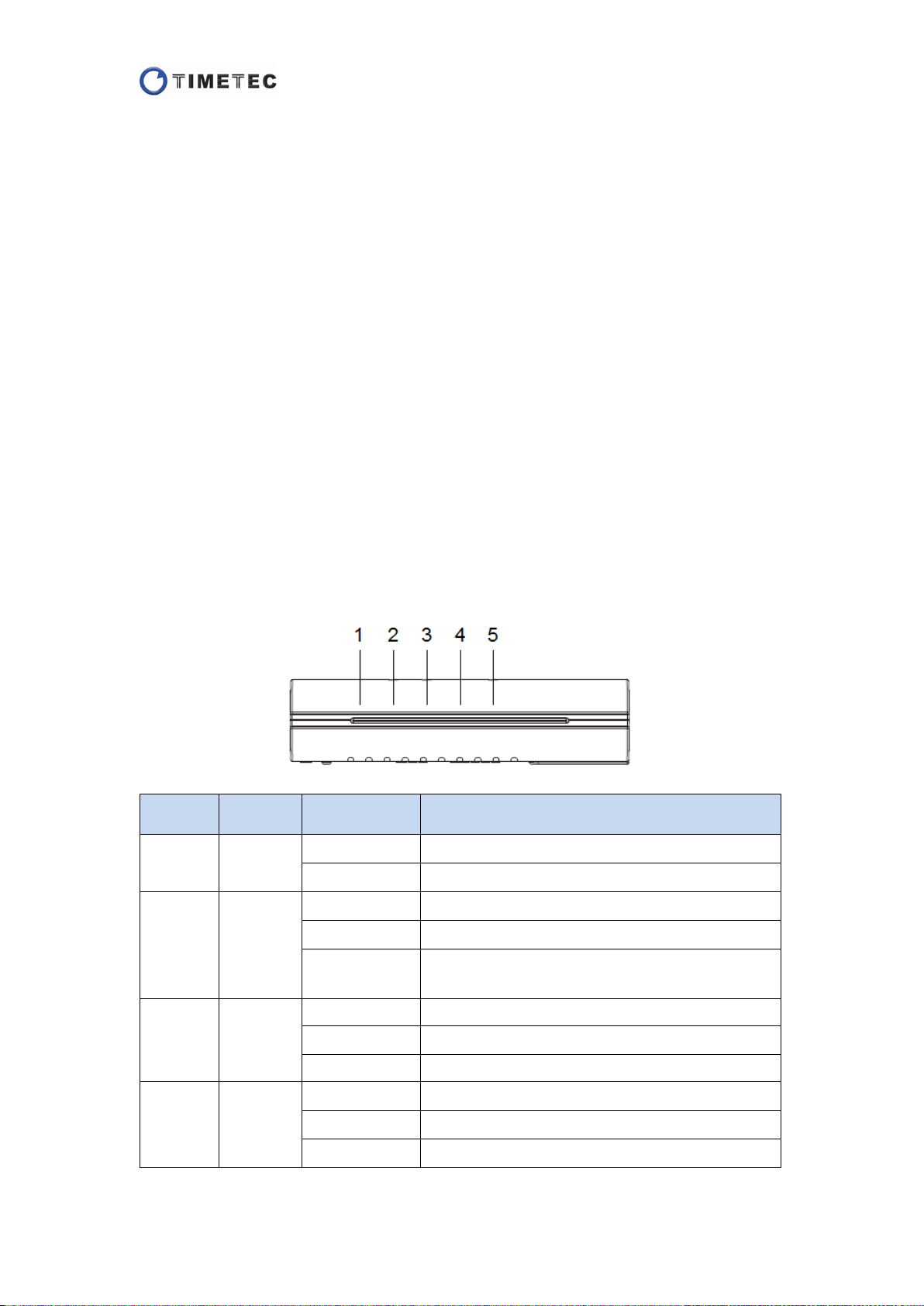
LED Indicators
The front panel of this wireless router contains four status lights as below. You can
use the status lights to confirm various conditions.
Number LED Light Status Description
1 PWR
2 WPS
On-Blue Power on
Off Power off
On-Red The device is starting.
Blink-Red WPS is working improperly.
Off
Blink-Blue The wireless function is enabled.
The device has completed starting; Or WPS is
successfully connected.
3 WLAN
4 LAN
Flashing-Blue
Off The wireless function is disabled.
On-Blue A device is linked to the LAN port.
Flashing-Blue
Off No link is detected on the LAN port.
Data is being sent or received over wireless.
Data is being sent or received over the LAN port.
4
Page 6
start Push Button
On-Blue A device is linked to the WAN port.
5
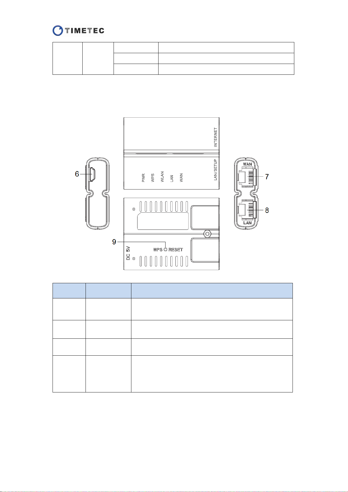
Panel
WAN
Flashing-Blue
Off No link is detected on the WAN port.
Data is being sent or received over the WAN port.
Number Name Description
6
7
8
9
USB Power
Jack
WAN Port This port connects to Internet.
LAN Port This port connects to a local computer.
WPS/Reset
Button
The device is powered by a MicroUSB connector.
Pressing this button once will
Configuration to setup WPS connection; pressing and
holding this button for more than 5 seconds will restore
the system to the factory settings.
5
Page 7
To Be Started
System Requirements
Each computer with an Ethernet adapter and TCP/IP protocol installed
Ethernet connection or Broadband Internet connection such as one DSL/cable
modem with an RJ45 connection
802.11n/b/g wireless adapters for wireless connection
A Web browser such as internet explorer 5.0 or higher
Connecting the Router
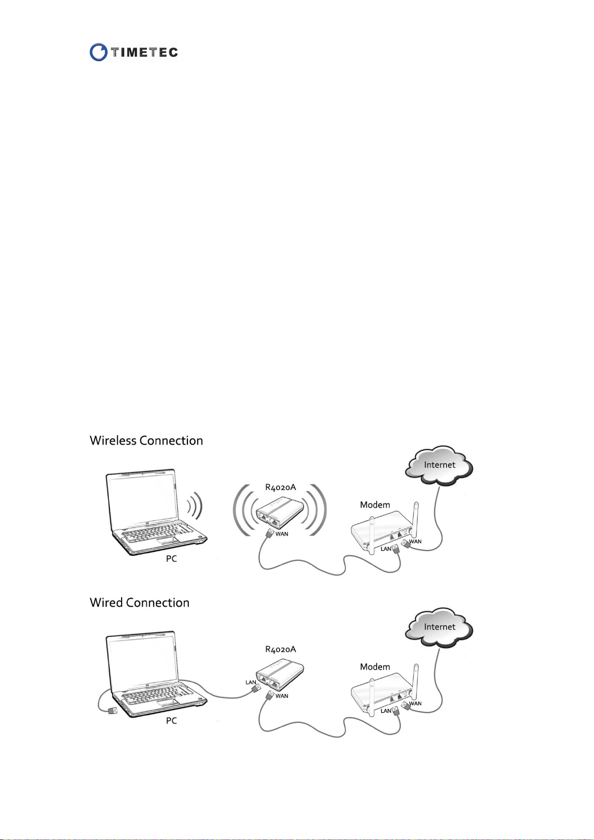
Operation Mode
In this router, there are two operation modes provided for you to select: Gateway
mode and Bridge mode. Before using the router, please choose an operation mode
first and then go on other configurations.
Gateway Mode
Gateway mode is known commonly as Router mode.
In this mode, the device is supposed to connect to Internet via ADSL/Cable Modem.
The connection type can be setup in WAN page by using PPPOE, DHCP client, PPTP
client, L2TP client or static IP.
The device can be accessed either via wired or wireless connections.
6
Page 8
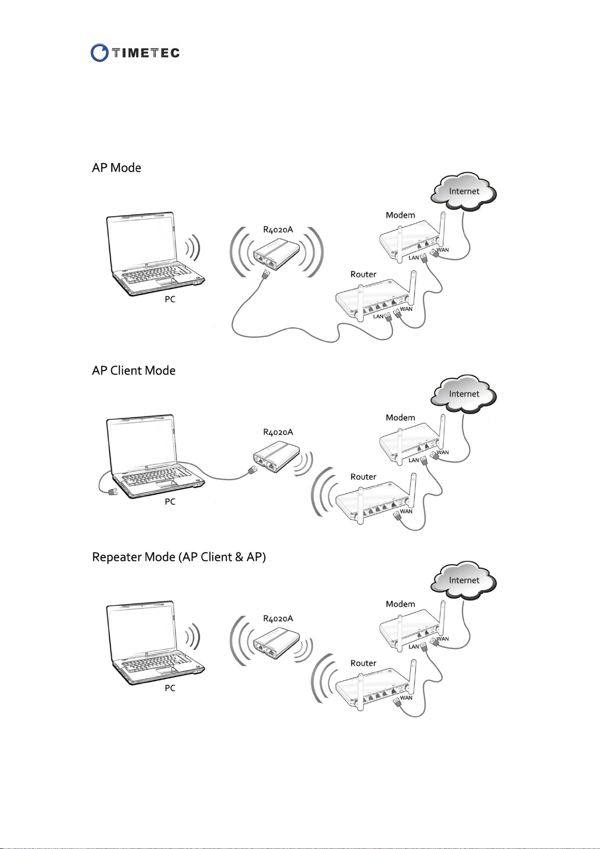
Bridge Mode
Bridge Mode is known commonly as AP Mode.
In this mode, all Ethernet ports and wireless interface are bridged together. All the
WAN related function and firewall are not supported.
In Bridge mode, the device can be set as AP, AP Client or Repeater.
7
Page 9
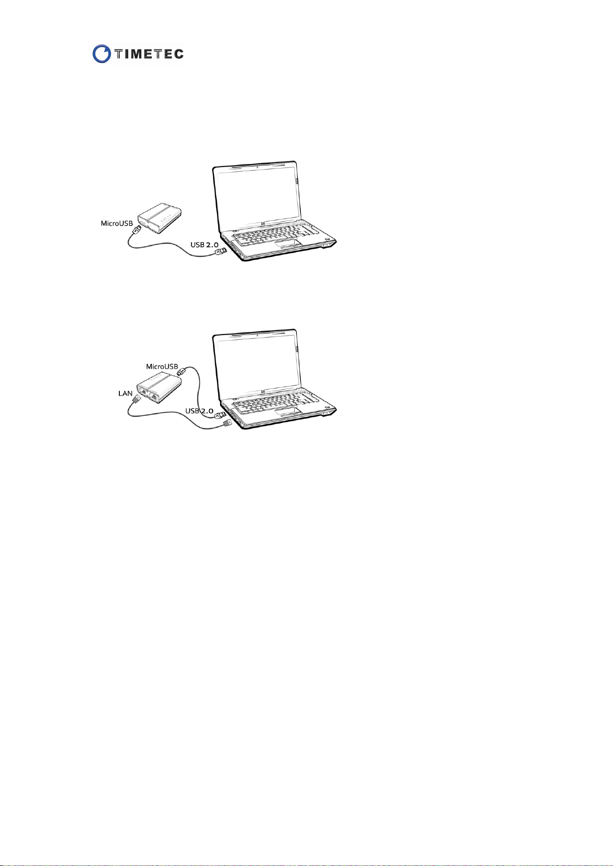
Power on the Router
To start the device, you should power on it first.
The device is powered by a MicroUSB connector. Connect the MicroUSB plug of the
USB cable to the power jack of the device, and connect the USB2.0 plug to the USB
port of the PC.
After starting the device, connect the PC to the LAN port of the device with a
network cable. Confirm on the PC that you connect to a new local network.
Note: Don’t connect the Internet cable to the WAN port at this time.
8
Page 10
Quick Setup Wizard
The Setup Wizard will help you getting online in several minutes by configuring the
basic functions of the wireless rou t er. You can use the Setup Wizard and manage the
router by a Web browser.
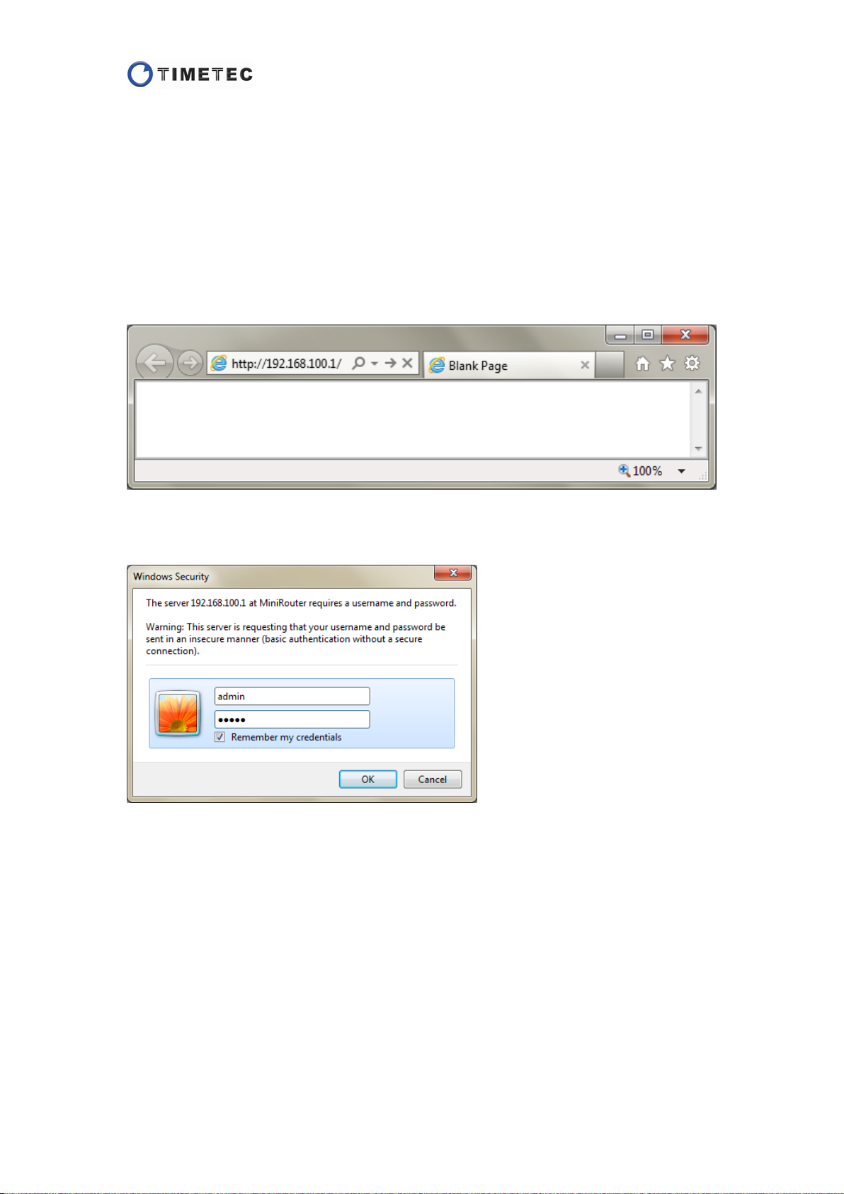
Login to the Web Management Interface
Open a web browser, type the default IP address of the router 192.168.100.1 in the
address field and press Enter.
You will see a login window after pressing E nt e r. Login it with “admin” for both User
name and Password.
9
Page 11
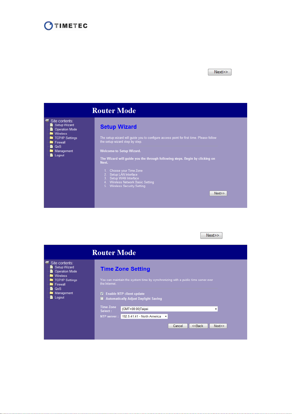
Setup Wizard for Gateway M o de (Router Mode)
Step 1:
The default operation mode is Router mode.
If this is the first time you enter the Web interface, you can click the
button directly in the home page.
If you want to change AP mode to Router mode, please select "Gateway" and apply
the change first in the "Operation Mode" page.
Step 2:
You can check the "Enable NTP client update" box to synchronize the time with an
NTP server, and select your time zone. After the setting, click the button.
Step 3:
In this step you can change the IP address (default 192.168.100.1) and subnet mask
(default 255.255.255.0) of the router. This IP is used for LAN connection to the router.
10
Page 12
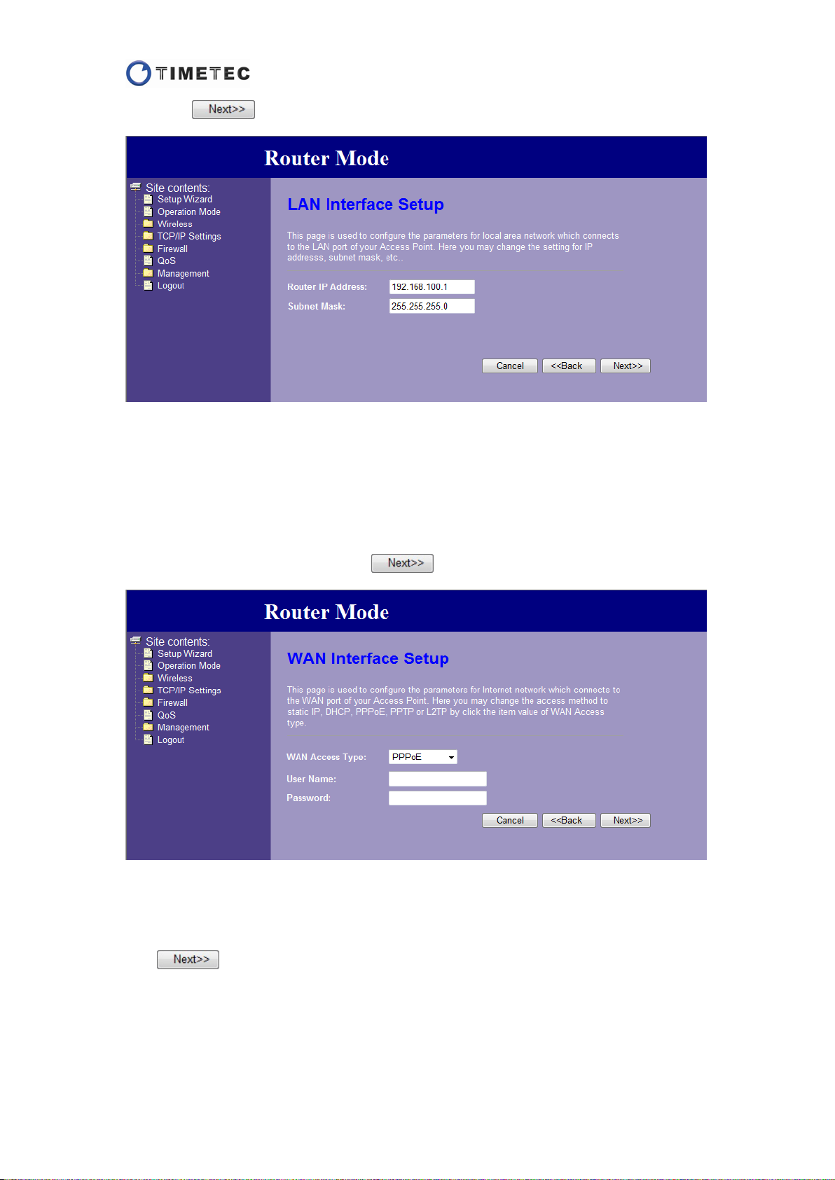
Click the button after confirming them.
Step 4:
Select one type of WAN access. There are 5 types provided: Static IP, DHCP Client,
PPPoE, PPTP, and L2TP.
If you are using a DSL/cable modem to access the Internet, please select PPPoE type,
and the user name and password are provided by your Internet Service Provider
(ISP).
Input the information and click the button.
Step 5:
Configure the basic settings of the wireless network. You can change the default SSID
to your own name so that you can easily find it out (Strongly recommended). Click
the button.
11
Page 13
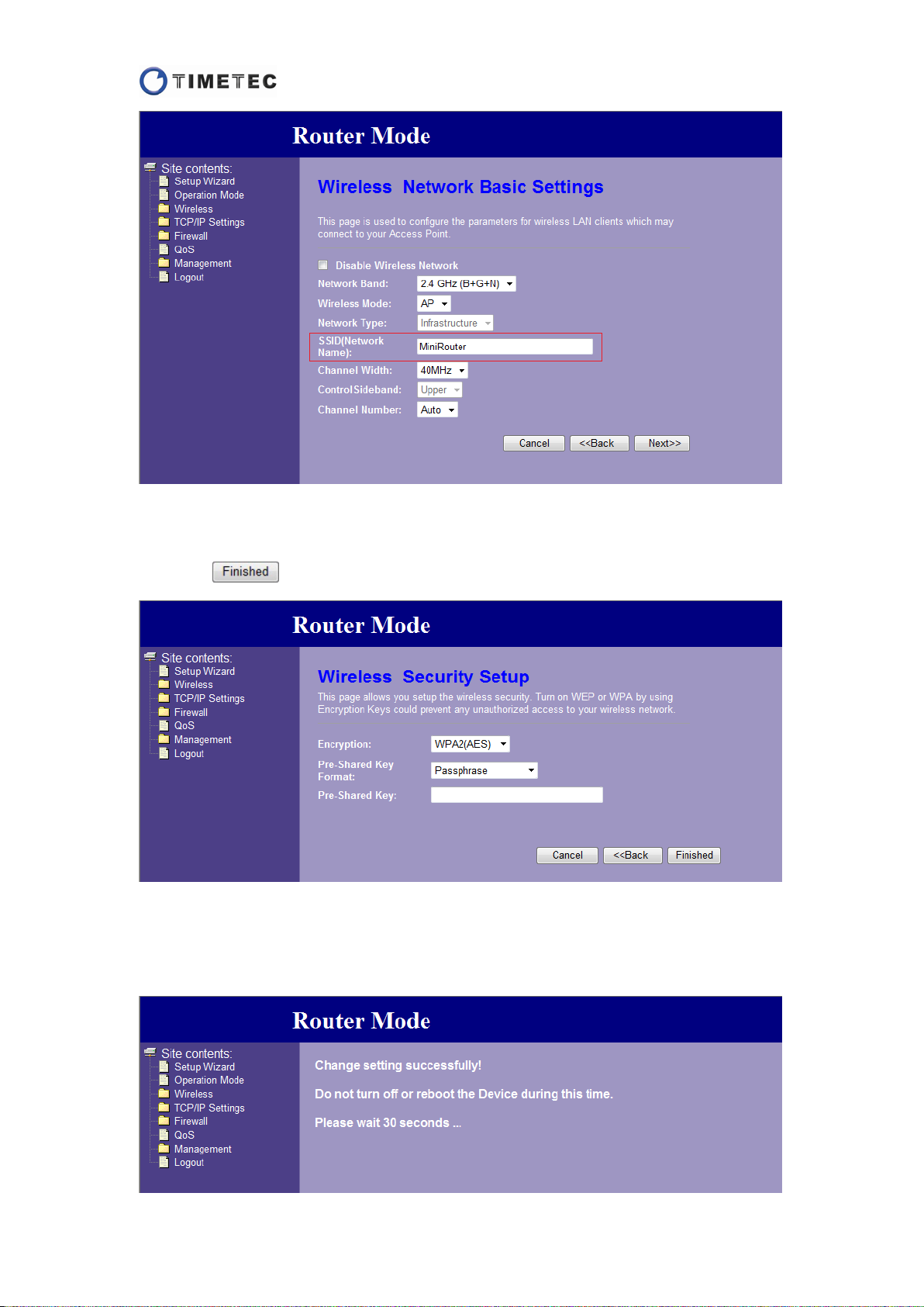
Step 6:
Use an encryption key to protect your wireless network (Strongly recommended).
Click the button to save the previous settings.
Step 7:
The system will save the wireless settings and reboot automatically. Please wait 30
seconds.
12
Page 14
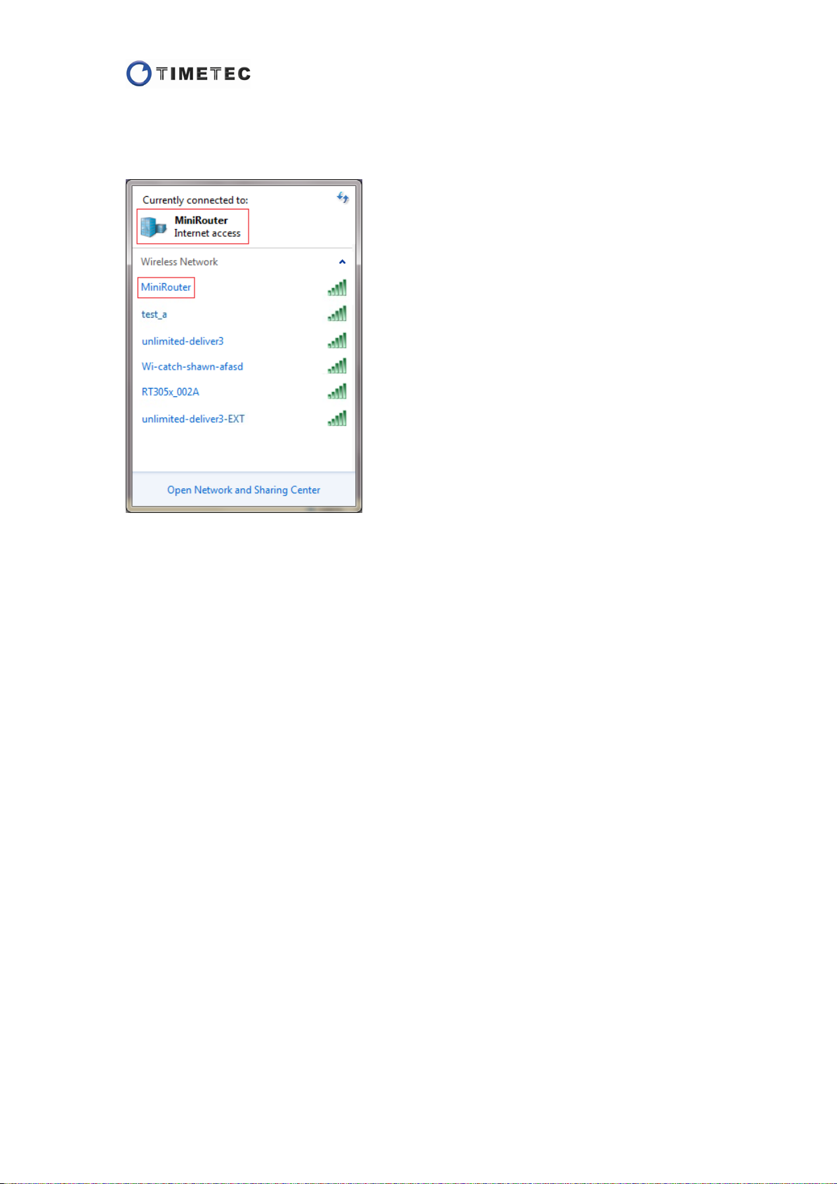
Step 8:
Plug the Internet cable into the WAN port of the device. The device will access the
Internet. You can also wirelessly connect to the network by the SSID you named.
13
Page 15
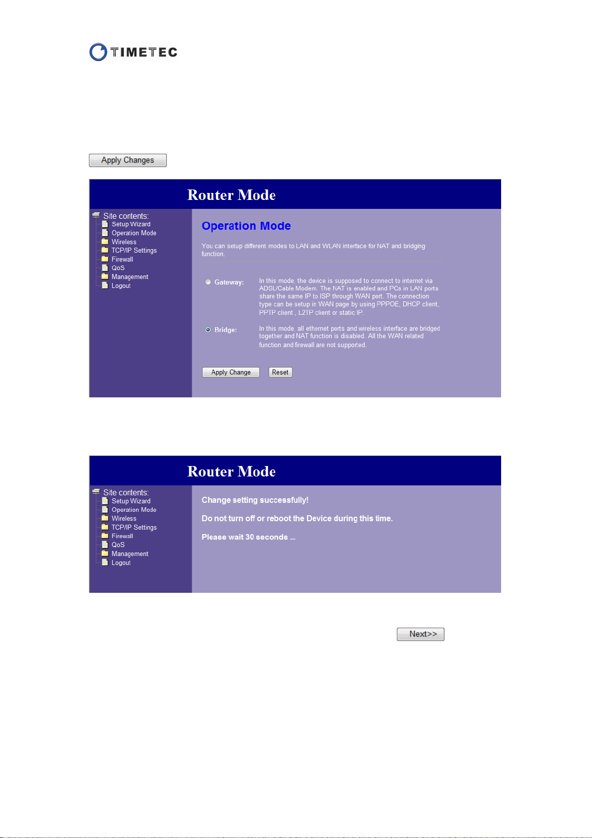
Setup Wizard for Bridg e M o de (AP Mode)
Step 1:
The default operation mode is Router mode. To change it to Bridge mode, please
click the "Operation Mode" on the left menu, then select "Bridge" and click the
button.
Step 2:
The system will save the change and reboot automatically. Please wait 30 seconds.
Step 3:
After rebooting, the home page will turn to AP mode. Click the button.
14
Page 16
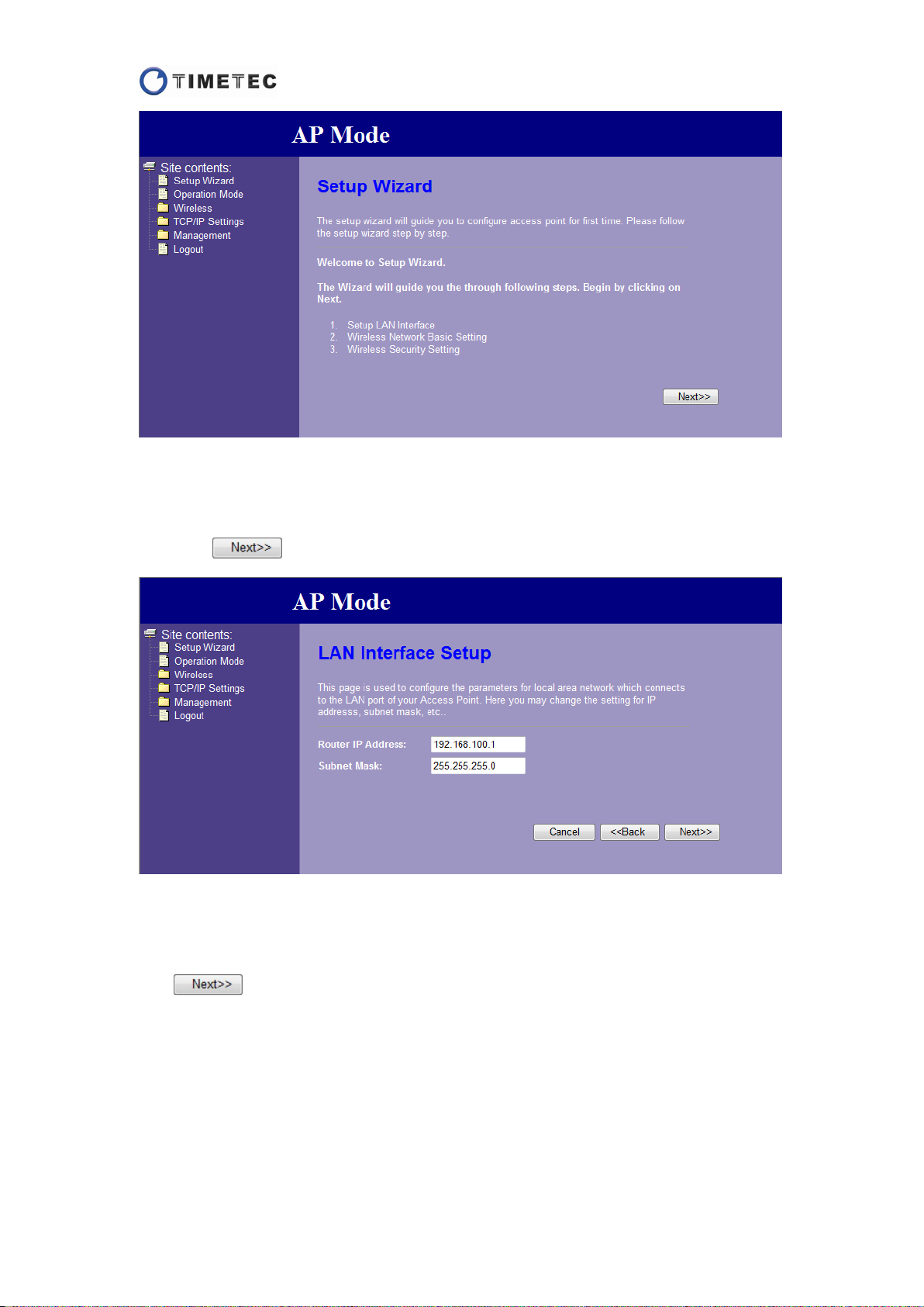
Step 4:
In this step you can change the IP address (default 192.168.100.1) and subnet mask
(default 255.255.255.0) of the router. This IP is used for LAN connection to the router.
Click the button after confirming them.
Step 5:
Configure the basic settings of the wireless network. You can change the default SSID
to your own name so that you can easily find it out (Strongly recommended). Click
the button.
15
Page 17
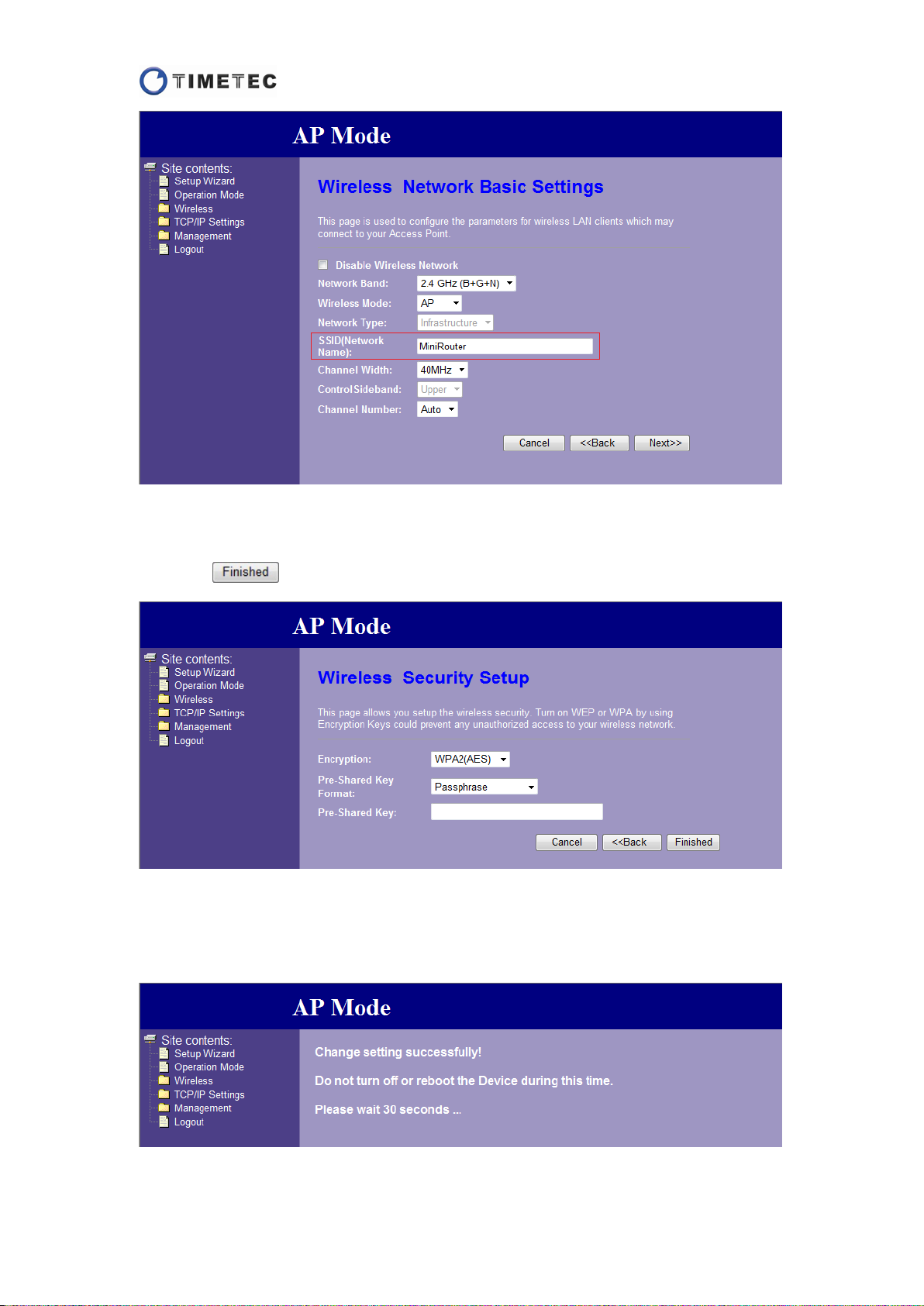
Step 6:
Use an encryption key to protect your wireless network (Strongly recommended).
Click the button to save the previous settings.
Step 7:
The system will save the wireless settings and reboot automatically. Please wait 30
seconds.
16
Page 18
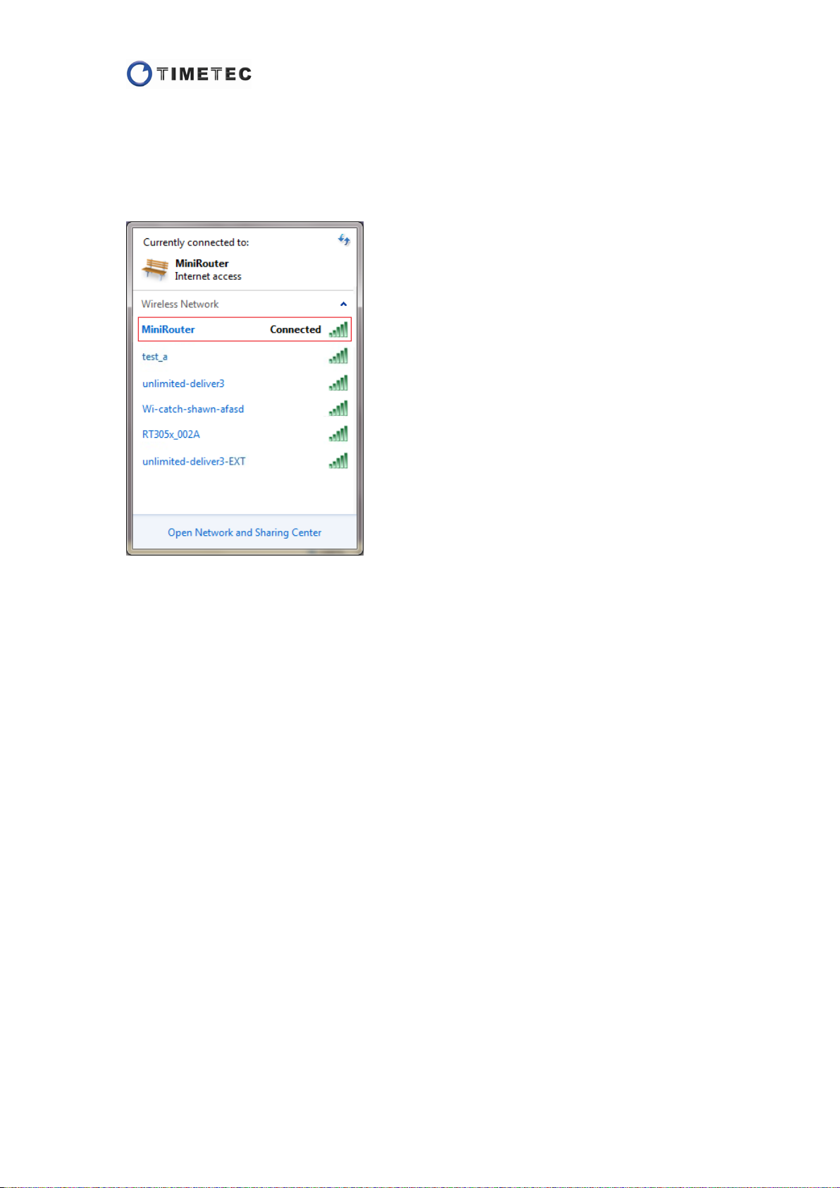
Step 8:
Disconnect the wired connection between the PC and the device, and plug the
Internet cable into either one port of the device.
The device will access the Internet, then you can connect to the wireless network by
the SSID you named.
The method for setting the router as an AP client or repeater can be seen in Wireless
Settings > Site Survey.
17
Page 19
Wireless Settings
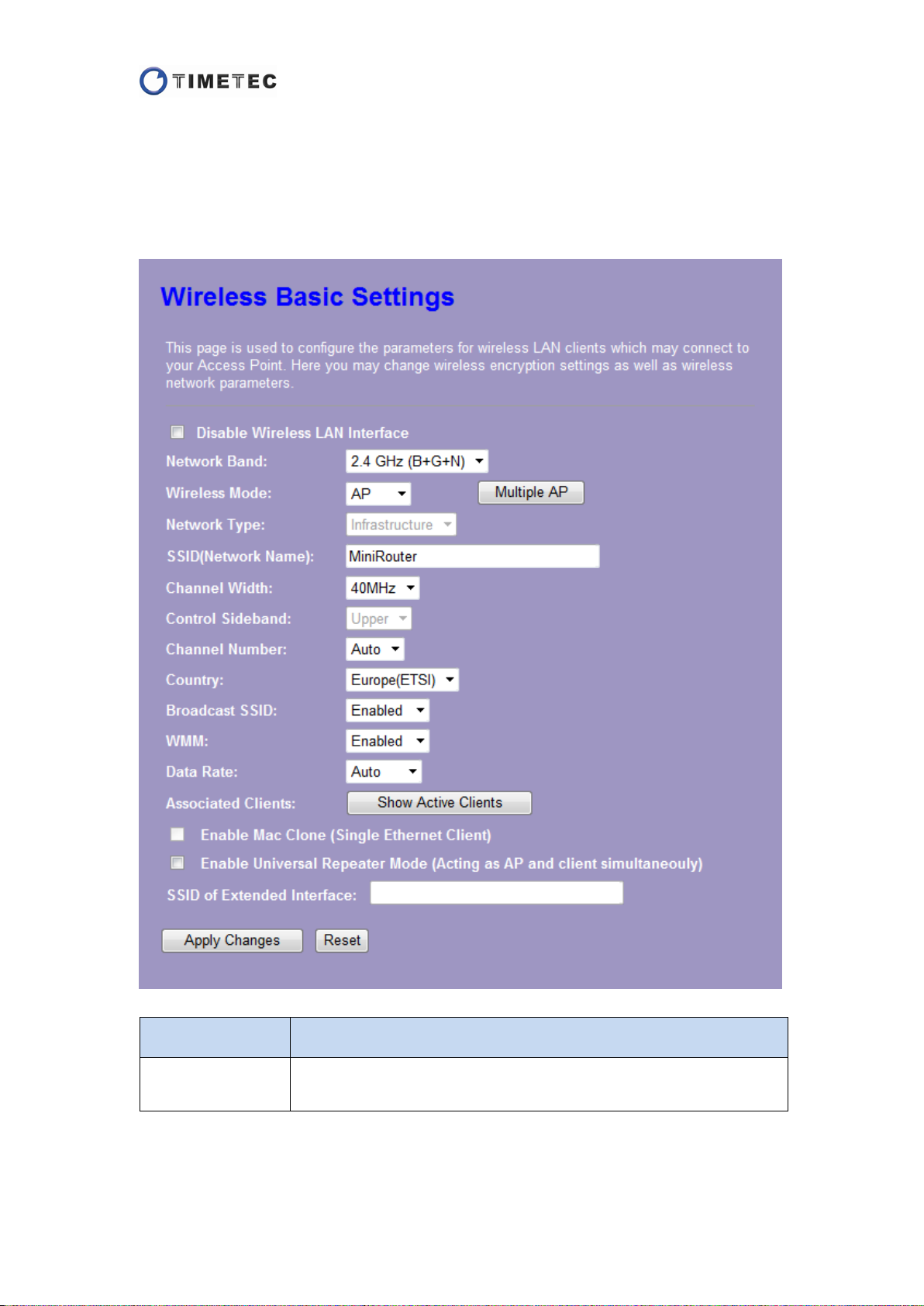
Basic Settings
You can configure the parameters for wireless LAN in this page.
Item Description
Disable Wireless
Network
Check the box to disable the wireless network.
18
Page 20

Network Band
Wireless Mode
Multiple AP
Network Type
SSID
There are 6 types of network band provided: 2.4GHz (B), 2.4 GHz (G),
2.4 GHz (N), 2.4GHz (B+G), 2.4 GHz (G+N) and 2.4 GHz (B+G+N).
You can select one type according to your wireless clients.
2.4 GHz (B+G+N) is strongly recommended.
There are 2 modes of wireless connection provided in AP mode: AP
and Client. Select one mode as you need.
Note: This function is not supported in Gateway mode.
This function provides 3 more access points for isolating the clients.
Click the
button you will see a page which shows the
wireless settings for Multiple APs. (See the details below)
Note: This function is not supported in
Infrastructure network.
There are 2 types provided in AP Client mode: Infrastructure and Ad
hoc. Select one type as you need.
Note: This function is only supported in AP Client mode.
Service Set Identifier (SSID) is used to identify one WLAN from the
others. The default SSID is "MiniRouter".
You can set an easily recognizable name according to your habit.
Channel Width
Control Sideband
Channel Number
Country
Broadcast SSID
There provides 20MHz and 40MHz to select as your channel width.
40MHz is only supported in 802.11n.
Note: This function is not supported in Infrastructure network.
The drop-down list is optional for “Upper” or “Lower” when you
select a specific number in Channel Number below.
This function is only applicable at 40MHz channel width.
Note: This function is not supported in Infrastructure network.
Channel Number can be selected to a specific number or retained
auto as default.
Channel Number will be different in different countries.
Country Lower Upper
USA (FCC), Canada (IC)
Europe (ETSI), Japan (MKK)
~
9 5~11
1
~
9 5~13
1
Spain 10 11
France 10 13
Note: This function is not supported in AP Client mode.
There contains USA (FCC), Canada (IC), Europe (ETSI), Spain, France,
and Japan (MKK) for your selection.
When this function is enabled, every wireless client within range can
see the SSID of this wireless router.
When this function is disabled, the SSID will be hidden and must be
added manually by the client.
WMM
When this function is enabled, video/audio data will have a higher
priority than the common data over wireless communications.
19
Page 21
Date Rate
There are various wireless data rate provided for 802.11b/g/n:
802.11b: 1, 2, 5.5, 11Mbps;
802.11g: 6, 9, 12, 18, 24, 36, 48, 54Mbps;
802.11n: MCS 0-15, up to 300Mbps.
Please select the data rate you need or retain it auto as default.
Associated Client
Enable Mac Clone
(Single Ethernet
Client)
Enable Universal
Repeater Mode
(Acting as AP and
client
simultaneously)
SSID of Extended
Interface
Click the
"Active Wireless Client Table" will pop up. You can see the status of
active wireless clients that are connected to the access point in the
table. (See the details below)
Note: This function is not supported in AP Client mode.
If your ISP requires you to register a MAC address, you can check this
function to clone the PC’s MAC address to the router to get online.
Note: This function is only supported in AP Client mode.
If you want to use this router as a repeater, please check this
function and set a SSID for the extended interface in below.
Note: This function is not supported in Gateway mode.
This SSID is used for the extended interface when this router works
as a repeater.
Note: This function is not supported in Gateway mode.
button, and then a window named
After setting the parameters, please click the button to save the
configurations, or click the button to reset the configurations before you
changed them.
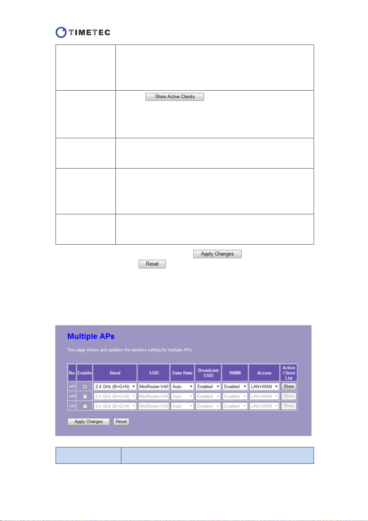
A. Multiple APs
To use Multiple APs, check the “Enable” box of AP1~3 and then you can configure
the parameters.
Item Description
20
Page 22
Access
There are 2 types provided to access the multiple APs: “LAN+WAN”
and “WAN”. If you select “WAN”, LAN connection to the AP will be
disabled.
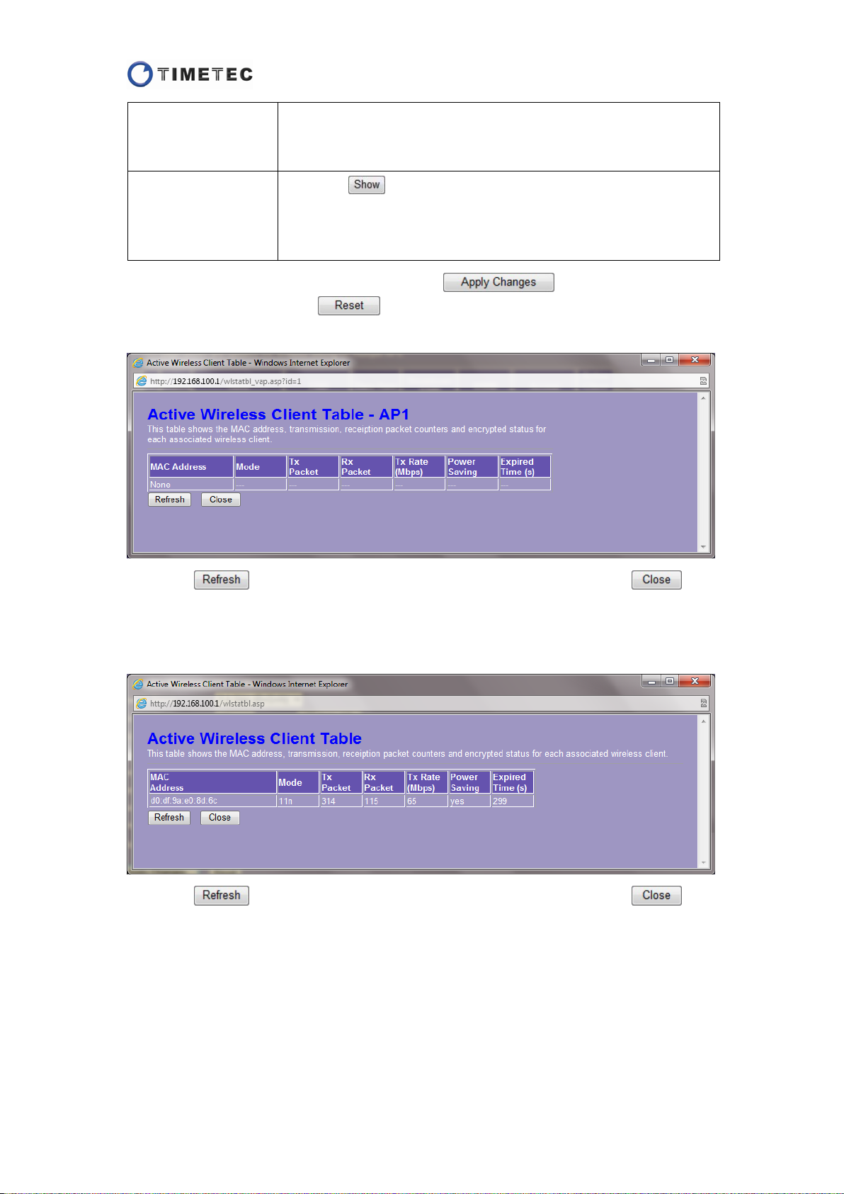
button in this column then you will see a pop-up
Active Client List
Click the
window named "Active Wireless Client Table" and the status of
active wireless clients that are connected to the AP listed in the
window.
After setting the parameters, please click the button to save the
configurations, or click the button to reset the configurations before you
changed them.
Click the button to refresh the clients’ information, or click the
button to close this pop up window.
B. Associated Client
Click the button to refresh the clients’ information, or click the
button to close this pop up window.
21
Page 23
This value determines the maximum size whether the packets will
If you experienced a high packet error rate, you may slightly
(RTS) Threshold determines the
the router, you may set it lower within the value range of 0 to
are the packets sent by the router to synchronize a
The time interval of the beacons can be set in
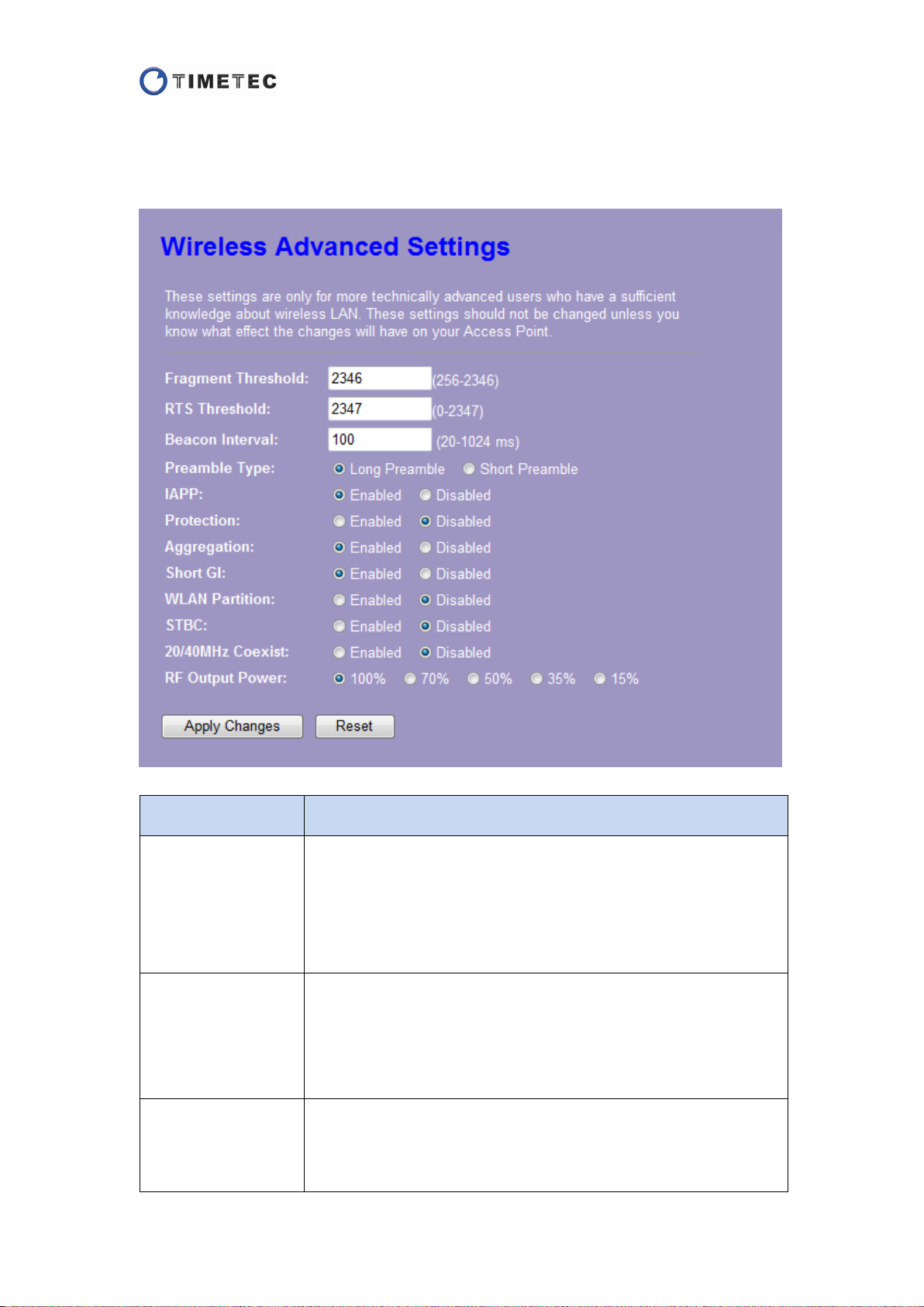
Advanced Settings
You can configure the advanced parameters for wireless LAN in this page.
Item Description
be fragmented.
Fragment Threshold
RTS Threshold
Beacon Interval
increase your fragmentation threshold within the value range of
256 to 2346.
The default value is 2346.
The value of Request to Send
maximum size whet her RTS/CTS access method will be deployed.
If there are any interferential long-distance clients connecting to
2347.
The default value is 2347.
The beacons
wireless network.
the range of 20 to 1024ms.
The default value is 100.
22
Page 24
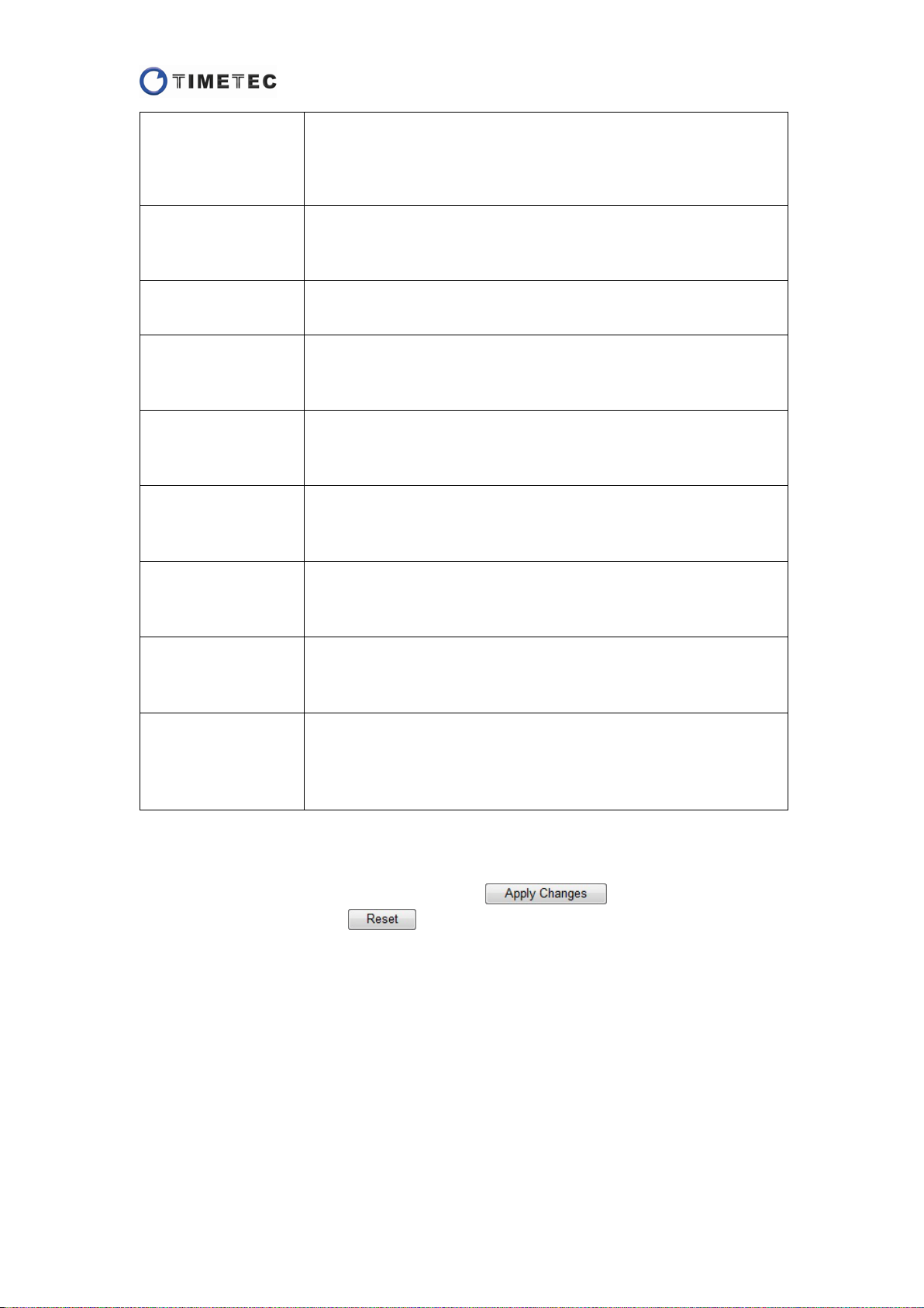
The preamble type defines the length of CRC blocks in the frames
You may select “Short
Access Point Protocol (IAPP) is used to solve the problem of
Preamble Type
IAPP
Protection
Aggregation
Short GI
WLAN Partition
STBC
over the wireless communications.
Preamble” when there is a large network-flow.
The default is “Long Preamble”.
Interswitching the access points by the wireless clients.
The default is “Enabled”.
Select “Enabled” to use the wireless protection mechanism.
The default is “Disabled”.
This function is used to reduce the blocking in a large data transfer
by aggregating multiple packets to one.
The default is “Enabled”.
This function is used to increase the data capacity by reducing the
Guard Interval (GI) time.
The default is “Enabled”.
This function is used to prevent associated wireless clients from
communicating with each other.
The default is “Disabled”.
Space-time block codes (STBC) can improve system capacity and
spectral efficiency.
The default is “Disabled”.
Select “enabled” to use a mixed channel width of 20MHz and
20/40MHz Coexist
RF Output Power
40MHz.
The default is “Disabled”.
Radio Frequency (RF) Output Power is used to control the signal
strength of the wireless network. It can be decreased to 70%, 50%,
35% or 15%.
The default value is 100%.
*It’s recommended to keep the default values unless you know exactly the effect will
be brought to this router by changing the parameters.
After setting the parameters, please click the button to save the
configurations, or click the button to reset the configurations before you
changed them.
23
Page 25
the RADIUS server used for
Security
The Security function protects your wireless network from invasion. We provide WEP
and WPA encryptions to secure your wireless network.
If you select “Disable” to close the Security function, any client can access the router
without password and any data will be transmitted without encryption. We strongly
recommend do not do that.
Before setting the encryption, please check the SSID (See the setting in Wireless >
Basic Settings) in the “Select SSID” drop-down list if you set multiple APs.
The Web interfaces will display differently in each working mode.
Router Mode & AP Mode
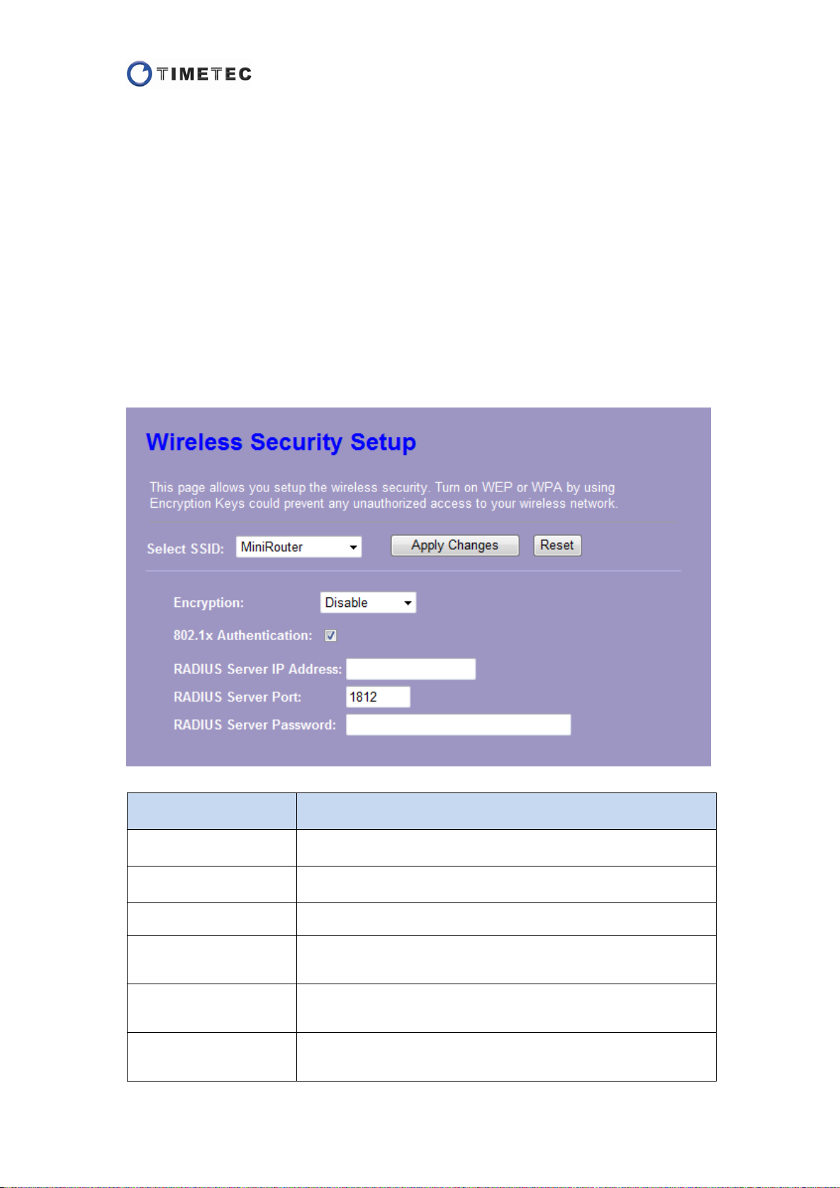
A. Disable Encryption
Item Description
Select SSID Select the SSID you want to set an encryption for.
Encryption Select “Disable”.
802.1x Authentication Check the box to set the 802.1x authentication.
RADIUS Server IP
Address
RADIUS Server Port
RADIUS Server
Password
Enter the IP address of
authentication.
The default UDP port for RADIUS server is 1812. If your RADIUS
server uses a different port, please set the actual port number.
Enter the password of the RADIUS server.
24
Page 26
used for
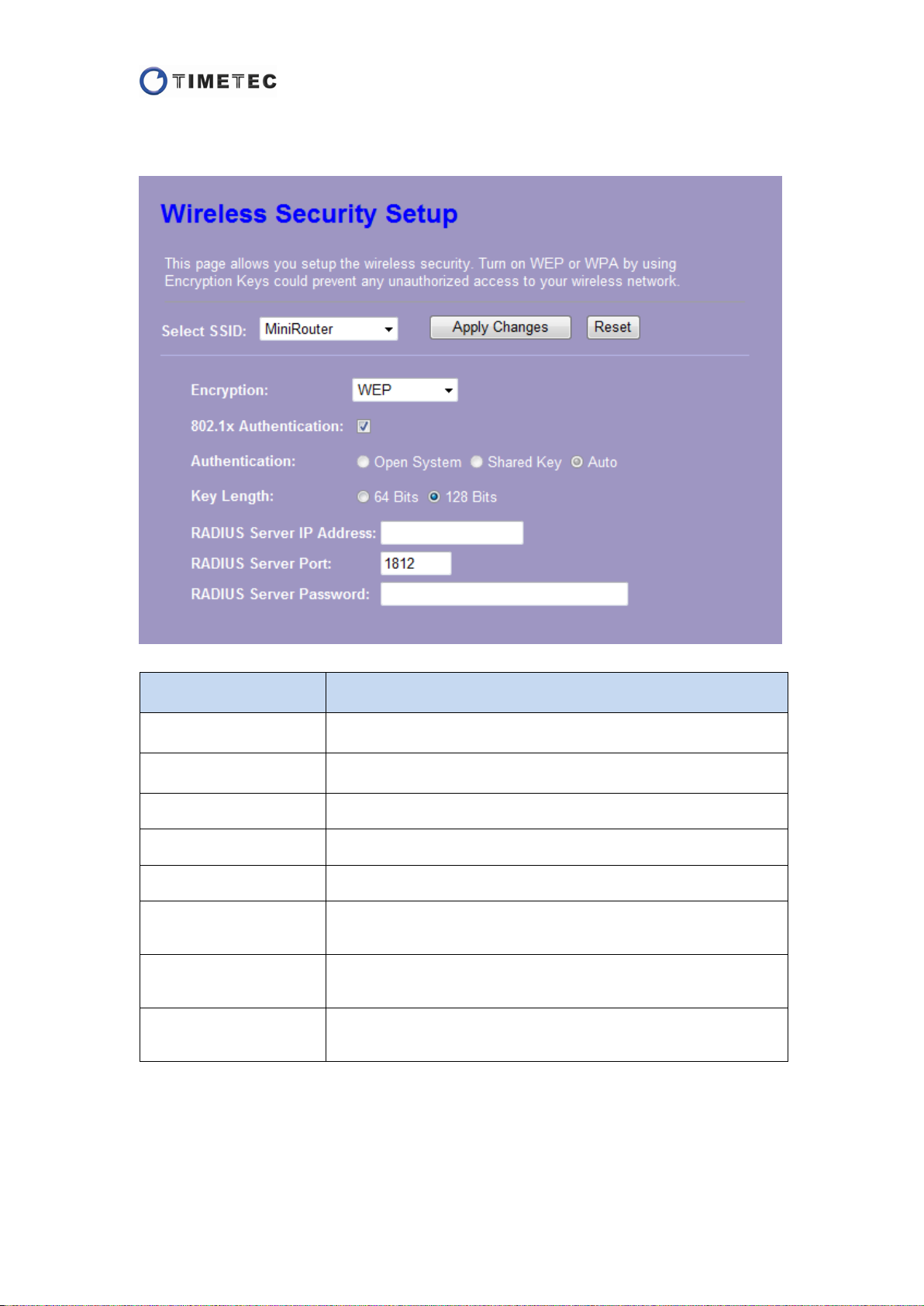
B. WEP Encryption
>> 802.1x Authentication
Item Description
Select SSID Select the SSID you want to set an encryption for.
Encryption Select “WEP”.
802.1x Authentication Check the box to set the 802.1x authentication.
Authentication This can’t be selected in 802.1x authentication.
Key Length Select “64-bit” or “128-bit” as the length of your password.
RADIUS Server IP
Address
RADIUS Server Port
RADIUS Server
Password
Enter the IP address of the RADIUS server that
authentication.
The default UDP port for RADIUS server is 1812. If your RADIUS
server uses a different port, please set the actual port number.
Enter the password of the RADIUS server.
>> Authentication
25
Page 27

There are three types provided: Open System, Shared Key, and
Item Description
Select SSID Select the SSID you want to set an encryption for.
Encryption Select “WEP”.
802.1x Authentication Uncheck this box.
Authentication
Auto. Select one authentication type according to your need.
Key Length Select “64-bit” or “128-bit” as the length of your password.
Key Format
Select “ASCII (13 characters)” or “Hex (26 characters)” as the
format of your password.
Enter your password according to the key format you selected.
Encryption Key
This password will be required when the wireless clients access
the router.
Show Password Select to show the password or not.
C. WPA Encryption
>> Enterprise (RADIUS) Authentication
26
Page 28

ver used for
Item Description
Select SSID Select the SSID you want to set an encryption for.
Encryption Select “WPA”.
Authentication Mode Select “Enterprise (RADIUS)” mode.
WPA Cipher Suite
RADIUS Server IP
Address
RADIUS Server Port
RADIUS Server
Password
There are 2 types provided: TKIP and AES. Select one according
to your need.
Enter the IP address of the RADIUS ser
authentication.
The default UDP port for RADIUS server is 1812. If your RADIUS
server uses a different port, please set the actual port number.
Enter the password of the RADIUS server.
>> Personal (Pre-Shared Key) Authentication
27
Page 29

Item Description
Select SSID Select the SSID you want to set an encryption for.
Encryption Select “WPA”.
Authentication Mode Select “Personal (Pre-Shared Key)” mode.
WPA Cipher Suite
Pre-Shared Key Format
There are 2 types provided: TKIP and AES. Select one according
to your need.
Select “Passphrase” or “Hex (64 characters)” as the format of
your password.
Enter your password according to the Pre-Shared key format
Pre-Shared Key
you selected. This password will be required when the wireless
clients access the router.
Show Password Select to show the password or not.
D. WPA2 Encryption
>> Enterprise (RADIUS) Authentication
28
Page 30

the RADIUS server used for
Item Description
Select SSID Select the SSID you want to set an encryption for.
Encryption Select “WPA2”.
Authentication Mode Select “Enterprise (RADIUS)” mode.
WPA2 Cipher Suite
RADIUS Server IP
Address
RADIUS Server Port
RADIUS Server
Password
There are 2 types provided: TKIP and AES. Select one according
to your need.
Enter the IP address of
authentication.
The default UDP port for RADIUS server is 1812. If your RADIUS
server uses a different port, please set the actual port number.
Enter the password of the RADIUS server.
>> Personal (Pre-Shared Key) Authentication
29
Page 31

you selected. This password will be required when the wireless
Item Description
Select SSID Select the SSID you want to set an encryption for.
Encryption Select “WPA2”.
Authentication Mode Select “Personal (Pre-Shared Key)” mode.
WPA2 Cipher Suite
Pre-Shared Key Format
There are 2 types provided: TKIP and AES. Select one according
to your need.
Select “Passphrase” or “Hex (64 characters)” as the format of
your password.
Enter your password according to the Pre-Shared key format
Pre-Shared Key
clients access the router.
Show Password Select to show the password or not.
E. WPA-Mixed Encryption
>> Enterprise (RADIUS) Authentication
30
Page 32

the RADIUS server used for
Item Description
Select SSID Select the SSID you want to set an encryption for.
Encryption Select “WPA-Mixed”.
Authentication Mode Select “Enterprise (RADIUS)” mode.
WPA/WPA2 Cipher
Suite
RADIUS Server IP
Address
RADIUS Server Port
RADIUS Server
Password
There are 2 types provided: TKIP and AES.
You can select different cipher suites for WPA and WPA2.
Enter the IP address of
authentication.
The default UDP port for RADIUS server is 1812. If your RADIUS
server uses a different port, please set the actual port number.
Enter the password of the RADIUS server.
>> Personal (Pre-Shared Key) Authentication
31
Page 33

Item Description
Select SSID Select the SSID you want to set an encryption for.
Encryption Select “WPA-Mixed”.
Authentication Mode Select “Personal (Pre-Shared Key)” mode.
WPA/WPA2 Cipher
Suite
Pre-Shared Key Format
There are 2 types provided: TKIP and AES.
You can select different cipher suites for WPA and WPA2.
Select “Passphrase” or “Hex (64 characters)” as the format of
your password.
Enter your password according to the Pre-Shared key format
Pre-Shared Key
you selected. This password will be required when the wireless
clients access the router.
Show Password Select to show the password or not.
AP Client Mode
A. Disable Encryption
32
Page 34

Item Description
Select SSID Select the SSID you want to set an encryption for.
Encryption Select “Disable”.
B. WEP Encryption
Item Description
Select SSID Select the SSID you want to set an encryption for.
Encryption Select “WEP”.
33
Page 35

There are three types provided: Open System, Shared Key, and
Authentication
Auto. Select one authentication type according to your need.
Key Length Select “64-bit” or “128-bit” as the length of your password.
Key Format
Select “ASCII (13 characters)” or “Hex (26 characters)” as the
format of your password.
Enter your password according to the key format you selected.
Encryption Key
This password will be required when the wireless clients access
the router.
Show Password Select to show the password or not.
C. WPA Encryption
>> Enterprise (RADIUS) Authentication
Item Description
Select SSID Select the SSID you want to set an encryption for.
Encryption Select “WPA”.
Authentication Mode Select “Enterprise (RADIUS)” mode.
WPA Cipher Suite
There are 2 types provided: TKIP and AES. Select one according
to your need.
>> Personal (Pre-Shared Key) Authentication
34
Page 36

you selected. This password will be required when the wireless
Item Description
Select SSID Select the SSID you want to set an encryption for.
Encryption Select “WPA”.
Authentication Mode Select “Personal (Pre-Shared Key)” mode.
WPA Cipher Suite
Pre-Shared Key Format
There are 2 types provided: TKIP and AES. Select one according
to your need.
Select “Passphrase” or “Hex (64 characters)” as the format of
your password.
Enter your password according to the Pre-Shared key format
Pre-Shared Key
clients access the router.
Show Password Select to show the password or not.
D. WPA2 Encryption
>> Enterprise (RADIUS) Authentication
35
Page 37

Item Description
Select SSID Select the SSID you want to set an encryption for.
Encryption Select “WPA2”.
Authentication Mode Select “Enterprise (RADIUS)” mode.
WPA Cipher Suite
There are 2 types provided: TKIP and AES. Select one according
to your need.
>> Personal (Pre-Shared Key) Authentication
36
Page 38

you selected. This password will be required when the wireless
Item Description
Select SSID Select the SSID you want to set an encryption for.
Encryption Select “WPA2”.
Authentication Mode Select “Personal (Pre-Shared Key)” mode.
WPA2 Cipher Suite
Pre-Shared Key Format
Pre-Shared Key
Show Password Select to show the password or not.
There are 2 types provided: TKIP and AES. Select one according
to your need.
Select “Passphrase” or “Hex (64 characters)” as the format of
your password.
Enter your password according to the Pre-Shared key format
clients access the router.
After setting the parameters, please click the button to save the
configurations, or click the button to reset the configurations before you
changed them.
37
Page 39

There are 3 modes provided: “Disable”, “Allow Listed” and “Deny
Access Control
To restrict the wireless connections, you can set up a control list in this page.
Note: This function is not supported in AP Client mode.
Item Description
Wireless Access
Control Mode
MAC Address
Comment You can add some description as comment for the MAC address.
Current Access
Control List
Listed”. Click the drop-down list to select one mode.
Select “Allow listed” or “Deny Listed” to allow or deny the wireless
clients access this device.
Select “Disable” to close the Access Control function.
Enter MAC address of the wireless client that you want to control.
Please avoid any colons (:) or dashes (-) in the address.
The list will show you the Access Control settings that added before.
If you want to remove one or more settings, check the “Select”
boxes of the records and click the
If you want to remove all the settings, click the
Click the
button to uncheck all the boxes.
button.
button.
After setting the parameters, please click the button to save the
configurations, or click the button to reset the configurations before you
changed them.
38
Page 40

Site Survey
The Site Survey function is used to scan the available wireless networks for the router
to connect.
Note: This function is not supported and hidden in Router Mode.
The Web interfaces will display differently in each working mode.
AP Mode
In AP mode, this function is only used to see the wireless networks within the range.
AP Client Mode
If you are setting the router as an AP client, confirm Network Type has changed to
“Client” in W ireless > Basic Settings.
If you are setting the router as a Repeater, confirm Enable Universal Repeater Mode
(Acting as AP and client simultaneously) is checked, and SSID of Extended Interface
is set in Wireless > Basic Settings.
Follow the steps to connect to the AP.
Step 1:
Click the button, you will see the wireless networks within the range,
select the one you want to connect and click the button.
39
Page 41

Step 2:
Input the encryption information of the wireless network you selected. Click the
button.
40
Page 42

Step 3:
It will take you a few seconds to connect to the selected wireless network. Please
wait patiently until it finished.
Step 4:
If the page shows "Connect successfully!", the device will be rebooted automatically.
Please don't do any operation and wait 30 seconds.
If the page shows "Connect failed 5!”, it means you provided the wrong password.
The page will turn back to the Site Survey page after 30 seconds. You can correct the
password or change a wireless network to connect.
41
Page 43

WPS
Wi-Fi Protected Setup (WPS) is used to simplify the security setup and management
of Wi-Fi networks. This router supports two methods for WPS: Personal
Identification Number (PIN) and Push Button Communication (PBC).
The Web interfaces will display differently in each working mode.
Router Mode & AP Mode
Item Description
Disable WPS
WPS Status
Self-PIN Number
Push Button
Configuration
Check the box and click the
WPS function.
The two options cannot be selected in Router and AP Mode.
Clicking the
unconfigured and remove the encryptions.
If you use this device as a client, you need to use this code when
connecting this device to other access points by PIN method.
When a Wi-Fi client wants to connect to this device by PBC method,
you can click the
WPS button on the router.
After that, please run the WPS and push the PBC button on the
client within 2 minutes.
42
button to disable the
button will set WPS function
button on this page or press the real
Page 44

When a Wi-Fi client wants to connect to this device by PIN method,
you can input the PIN code of the client and click the
Client PIN Number
Current Key Info The list displays the information of the configured encryptions.
button.
After that, please run the WPS and push the PIN button on the client
within 2 minutes.
AP Client Mode
Item Description
Disable WPS
Self-PIN Number
PIN Configuration
Push Button
Configuration
Check the box and click the
WPS function.
If you use this device as a client, you need to use this code when
connecting this device to other access points by PIN method.
When you connect to an access point by PIN method, you need to
click the
When you connect to an access point by PBC method, you need to
click the
button on the router after the access point start PBC.
button after the access point start PIN.
button on this page or press the real WPS
button to disable the
43
Page 45

Schedule
You can make your wireless schedule rule to control the work time of the router.
Item Description
Enable Wireless
Schedule
Schedule
Check the box to set a wireless schedule.
Enable Check one record or more.
Day
From & To
Select everyday or a specific work day from Sunday to
Saturday in this column.
Set the start and end time in Column "From" and "To"
within 24 hours.
Note: In order to ensure the schedule work normally, please configure system time in
Management > Time Zone Setting before using this function.
After setting the schedule, please click the button to save the
configurations, or click the button to reset the configurations before you
changed them.
44
Page 46

must use this IP to enter the Web management interface. If you
TCP/IP
LAN Interface
In this page, you can configure the parameters for the local network using a LAN
connection to the router.
The Web interfaces will display differently in each working mode.
Router Mode
Item Description
This IP address is the LAN port IP address of your router.
IP Address
Subnet Mask
Default Gateway
You
changed the IP, please use the new IP to enter the Web interface.
The default IP is 192.168.100.1.
The subnet mask is an address code which determines the size of
the network. You can set it as you need.
The default size is 255.255.255.0.
A gateway is a network point accessing to another network.
The default gateway is 0.0.0.0.
45
Page 47

DHCP Client Range
DHCP Lease Time
In the fields, you can type an available range according to the IP
Address above to specify DHCP Clients’ IP addresses.
The default range is from 192.168.100.100 to 192.168.100.200.
Click the
DHCP Client Table" will pop up. The status of active DHCP clients
that connected to the router will be displayed in the table. (See the
details below)
DHCP Lease Time is used to limit the usage time of an IP address on
a DHCP client. When the time is exceeded, the DHCP server will
release the IP. You can set the lease time within the range of 1 to
10080 minutes.
The default value is 480 minutes.
button, and then a window named "Active
button then you will enter the static
Static DHCP
Domain Name
802.1d Spanning
Tree
Auto IP Address
Diversion
Click the
DHCP setup page. In this page, you can assign an available static IP
to a DHCP client. (See the details below)
Domain name is used to provide an easy way to access the Web
interface. You can use it as well as the IP address.
The Spanning Tree Protocol (STP) is a network protocol that ensures
a loop-free network while providing redundant connections.
The default is "Disabled".
This function is used to solve the conflict between WAN’s IP address
and LAN’s when they’re in the same subnet.
The default is "Disabled".
After setting the parameters, please click the button to save the
configurations, or click the button to reset the configurations before you
changed them.
A. DHCP Client Range > Show Client
Click the button to refresh the clients’ information, or click the
button to close this pop up window.
46
Page 48

B. Static DHCP
Item Description
Enable Static DHCP Check the box to enable the Static DHCP function.
IP Address Assign an available IP address for the client.
Input the MAC address of the client which you want to assign an IP
MAC Address
Comment You can add some description as comment for the MAC address.
Static DHCP List
address for.
Please avoid any colons (:) or dashes (-) in the address.
The list will show you the assigning information of the clients.
If you want to remove one or more settings, check the “Select”
boxes of the records and click the
If you want to remove all the settings, click the
Click the
button to uncheck all the boxes.
button.
button.
After setting the parameters, please click the button to save the
configurations, or click the button to reset the configurations before you
changed them.
47
Page 49

AP Mode & AP Client Mode
In AP and AP Client mode, LAN interface is disabled.
48
Page 50

WAN Interf ace
In this page, you can configure the parameters for connecting to Internet. There are 5
types for Internet access provided: Static IP, DHCP Client, PPPoE, PPTP and L2TP.
Note: WAN Interface is only supported in Gateway mode. It’s disabled and hidden in
Bridge mode.
A. Static IP
49
Page 51

Item Description
WAN Access Type Select Static IP type to access the WAN.
IP Address Input the IP address that provided by your ISP.
Subnet Mask Input the Subnet Mask provided by your ISP.
Default Gateway Input the Default Gateway that provided by your ISP.
Maximum Transfer Unit (MTU) determines the largest size of
MTU Size
a packet that can be sent over a network.
You can set the MTU size between 1400 and 1500 bytes.
The default value is 1500.
DNS 1-3
Clone MAC Address
Enable UPnP
Enable IGMP Proxy
Enable Ping Access on
WAN
Enable Web Server Access
on WAN
Input the Domain Name Server (DNS) address that provided
by your ISP. You can set up to three DNS addresses.
There are two ways to clone MAC address.
You can manually input the MAC address in textbox, and
click the
button to save it; or click the
button to copy the MAC address from your
network card automatically.
Check the box to enable
Universal Plug and Play (UPnP)
function.
The default is enabled.
This function is used to intercept Internet Group
Management Protocol (IGMP) packets between the router
and other clients to setup a multicast group.
The default is enabled.
This function is used to allow access Ping on WAN port.
The default is not enabled.
This function is used to allow access the Web Interface from
WAN port.
The default is not enabled.
Enable IPsec pass through
on VPN connection
Enable PPTP pass through
on VPN connection
Enable L2TP pass through
on VPN connection
This function is used to allow Internet Protocol Security
(IPsec) packets from VPN connection pass through the
router.
The default is enabled.
This function is used to allow Point to Point Tunneling
Protocol (PPTP) packets from VPN connection pass through
the router.
The default is enabled.
This function is used to allow Layer 2 Tunneling Protocol
(L2TP) packets from VPN connection pass through the
router.
The default is enabled.
50
Page 52

lists the MAC addresses you have
and click the
Enable IPv6 pass through
on VPN connection
Enable PPPoE pass through
on VPN connection
History MAC Table
B. DHCP Client
This function is used to allow Internet Protocol Version 6
(IPv6) packets from VPN connection pass through the router.
The default is not enabled.
This function is used to allow Point-to-Point Protocol over
Ethernet (PPPoE) packets from VPN connection pass through
the router.
The default is not enabled.
The History MAC Table
cloned.
If you want to remove one or more history records, check
the “Select” boxes of the records
button.
If you want to remove all the history records, click the
button.
Click the
button to uncheck all the boxes.
Note: The table can save up to three MAC addresses.
Item Description
WAN Access Type Select DHCP Client type to access the WAN.
Host Name
You can set a host name for the router if your Internet service
has been configured with a host name.
MTU Size
You can set the MTU size between 1400 and 1492 bytes.
The default value is 1492.
51
Page 53

There are two ways to set DNS: "Attain DNS Automatically" and
"Set DNS Manually".
DNS
You can select “Attain DNS automatically" if your DNS provided
by ISP is dynamic; Or select "Set DNS Manually" and input the
DNS addresses that provided by your ISP. You can set up to
three DNS addresses.
*The other parameters can be set as Static IP type.
C. PPPoE
Item Description
WAN Access Type Select PPPoE type to access the WAN.
User Name & Password Input the user name and password provided by your ISP.
Service Name Input the service name if provided by your ISP.
There are 3 connection types provided: "Continuous", "Connect
on Demand" and "Manual".
Connection Type
If you select "Manual" type, you can click the
button to start a connection, and click the
button
to disconnect it.
The default is "Continuous" type.
52
Page 54

Idle Time
When you select "Connect on Demand" as connection type, you
can set an idle time between 1 to 1000 minutes for demand.
The default value is 5 minutes.
MTU Size
DNS
You can set the MTU size between 1360 and 1492 bytes.
The default value is 1454.
There are two ways to set DNS: "Attain DNS Automatically" and
"Set DNS Manually".
You can select “Attain DNS automatically" if your DNS provided
by ISP is dynamic; Or select "Set DNS Manually" and input the
DNS addresses that provided by your ISP. You can set up to
three DNS addresses.
*The other parameters can be set as Static IP type.
D. PPTP
Item Description
WAN Access Type Select PPTP type to access the WAN.
53
Page 55

IP Address Input the IP address that provided by your ISP.
Subnet Mask Input the Subnet Mask provided by your ISP.
Default Gateway Input the Default Gateway that provided by your ISP.
User Name & Password Input the user name and password provided by your ISP.
There are 3 connection types provided: "Continuous", "Connect
on Demand" and "Manual".
Connection Type
If you select "Manual" type, you can click the
button to start a connection, and click the
button
to disconnect it.
The default is "Continuous" type.
When you select "Connect on Demand" as connection type, you
Idle Time
can set an idle time between 1 to 1000 minutes for demand.
The default value is 5 minutes.
MTU Size
Request MPPE
Encryption
Request MPPC
Compression
You can set the MTU size between 1400 and 1460 bytes.
The default value is 1460.
Check the box to enable Microsoft Point-to-Point Encryption
(MPPE) function on VPN connection via PPTP.
Check the box to enable Microsoft Point-to-Point Compression
(MPPC) function on VPN connection via PPTP.
There are two ways to set DNS: "Attain DNS Automatically" and
"Set DNS Manually".
DNS
You can select “Attain DNS automatically" if your DNS provided
by ISP is dynamic; Or select "Set DNS Manually" and input the
DNS addresses that provided by your ISP. You can set up to
three DNS addresses.
*The other parameters can be set as Static IP type.
E. L2TP
54
Page 56

Item Description
WAN Access Type Select L2TP type to access the WAN.
IP Address Input the IP address that provided by your ISP.
Subnet Mask Input the Subnet Mask provided by your ISP.
Default Gateway Input the Default Gateway that provided by your ISP.
User Name & Password Input the user name and password provided by your ISP.
There are 3 connection types provided: "Continuous",
"Connect on Demand" and "Manual".
Connection Type
If you select "Manual" type, you can click the
button to start a connection, and click the
button to disconnect it.
The default is "Continuous" type.
55
Page 57

Idle Time
When you select "Connect on Demand" as connection type,
you can set an idle time between 1 to 1000 minutes for
demand.
The default value is 5 minutes.
MTU Size
DNS
You can set the MTU size between 1400 and 1460 bytes.
The default value is 1460.
There are two ways to set DNS: "Attain DNS Automatically"
and "Set DNS Manually".
You can select “Attain DNS automatically" if your DNS
provided by ISP is dynamic; Or select "Set DNS Manually"
and input the DNS addresses that provided by your ISP. You
can set up to three DNS addresses.
*The other parameters can be set as Static IP type.
After setting the parameters, please click the button to save the
configurations, or click the button to reset the configurations before you
changed them.
56
Page 58

Firewall
Firewall is a network security tool that protects the computer from network attacks.
Note: Firewall is only supported in Gateway mode. It’s disabled and hidden in Bridge
mode.
Port Filtering
This function is used to restrict the data pass through the ports in a specified range.
Item Description
Enable Port Filtering Check the box to enable the port filtering function.
Port Range
Protocol
Comment You can add some description as comment for the ports.
Current Filter Table
Set the range for the ports that you want to restrict data pass
through.
There are 3 types of protocol provided: TCP/UDP, TCP and UDP.
Select one type as you need.
The table lists the filtered ports you have added.
If you want to remove one or more records, check the “Select”
boxes of the records and click the
If you want to remove all the settings, click the
button.
Click the
button to uncheck all the boxes.
button.
After setting the parameters, please click the button to save the
configurations, or click the button to reset the configurations before you
changed them.
57
Page 59

IP Filtering
This function is used to restrict the data pass through a specified IP address.
Item Description
Enable IP Filtering Check the box to enable the IP filtering function.
Local IP Address Set the IP address that you want to restrict data pass through.
Protocol
Comment You can add some description as comment for the IP address.
Current Filter Table
There are 3 types of protocol provided: TCP/UDP, TCP and UDP.
Select one type as you need.
The table lists the filtered IP addresses you have added.
If you want to remove one or more records, check the “Select”
boxes of the records and click the
If you want to remove all the settings, click the
button.
Click the
button to uncheck all the boxes.
button.
After setting the parameters, please click the button to save the
configurations, or click the button to reset the configurations before you
changed them.
58
Page 60

MAC Filtering
This function is used to restrict the data pass through the device with a specified
MAC address.
Item Description
Enable MAC Filtering Check the box to enable the MAC filtering function.
MAC Address
Comment
Current Filter Table
Set the MAC address of the device that you want to restrict
data pass through.
You can add some description as comment for the MAC
address.
The table lists the filtered MAC addresses you have added.
If you want to remove one or more records, check the “Select”
boxes of the records and click the
If you want to remove all the settings, click the
button.
Click the
button to uncheck all the boxes.
button.
After setting the parameters, please click the button to save the
configurations, or click the button to reset the configurations before you
changed them.
59
Page 61

Port Forwarding
This function is used to forward the visitors to the device with a specified IP when
they visit through a specified port.
Item Description
Enable Port Forwarding Check the box to enable the port forwarding function.
IP Address Set the IP address that you want to forward the visitors to.
Protocol
Port Range
Comment You can add some description as comment.
Current Filter Table
There are 3 types of protocol provided: TCP/UDP, TCP and UDP.
Select one type as you need.
Set the range for the ports that will forward to a specified IP
address.
The table lists the forwarded ports you have added.
If you want to remove one or more records, check the “Select”
boxes of the records and click the
If you want to remove all the settings, click the
button.
Click the
button to uncheck all the boxes.
button.
After setting the parameters, please click the button to save the
configurations, or click the button to reset the configurations before you
changed them.
60
Page 62

URL Filtering
This function is used to restrict the data pass through a specified URL address.
Item Description
Enable URL Filtering Check the box to enable the URL filtering function.
URL Address
Current Filter Table
Set the URL address of the device that you want to restrict data
pass through.
The table lists the filtered URL addresses you have added.
If you want to remove one or more records, check the “Select”
boxes of the records and click the
If you want to remove all the settings, click the
button.
Click the
button to uncheck all the boxes.
button.
After setting the parameters, please click the button to save the
configurations, or click the button to reset the configurations before you
changed them.
61
Page 63

DMZ
The Demilitarized Zone (DMZ) function is used to forward the visitors to a specified
device when they visit the router from WAN.
Check the "Enable DMZ" box to enable this function, and then input the IP address of
the DMZ host. Click the button to save the configuration.
62
Page 64

VLAN
Virtual Local Area Network (VLAN) is created to provide the segmentation services
traditionally provided by routers.
Item Description
Enable VLAN
Ethernet/Wireless This column lists the available ports including virtual APs.
WAN/LAN This column marks the ports as WAN or LAN.
Tag Check the box to set a tag for a VLAN.
VID
Priority You can set priorities for the VLANs from 1 to 7.
CFI
Check the box to enable the Virtual Local Area Network (VLAN)
function, and then check a record.
VID is used to identify and classify the VLANs. VID can be set
from 1 to 4096.
When the box is check, the data frames on the VLAN won’t be
forwarded.
After setting the parameters, please click the button to save the
configurations, or click the button to reset the configurations before you
changed them.
63
Page 65

QoS
QoS (Quality of Service) is a service that used to improve the quality of network
communication by setting rules.
Note: QoS is only supported in Gateway mode. It’s disabled and hidden in Bridge
mode.
64
Page 66

Item Description
Enable QoS Check the box to enable QoS function.
Automatic Uplink
Speed
Manual Uplink Speed
(Kbps)
Automatic Downlink
Speed
Manual Downlink
Speed (Kbps)
Address Type
Local IP Address
MAC Address
Mode
Uplink Bandwidth
(Kbps)
Check the box to set an automatic uplink speed.
Uncheck the “Automatic Uplink Speed” box, and then you can
manually set the uplink speed.
Check the box to set an automatic downlink speed.
Uncheck the “Automatic Downlink Speed” box, and then you
can manually set the downlink speed.
There are two types of address provided can be used in a QoS
rule: IP and MAC. Please select one type.
When you select IP address type, you can input the IP range you
will make a rule for.
When you select MAC address type, you can input the MAC
address you will make a rule for.
There are 2 mode provided to limit the speed: Guaranteed
minimum bandwidth and Restricted maximum bandwidth.
Select one type according to your need.
Input an appropriate uplink bandwidth.
Downlink Bandwidth
(Kbps)
Comment You can add some description as comment for the rule.
Current QoS Rules
Table
Input an appropriate downlink bandwidth.
The list displays the QoS rules you have set.
If you want to remove one or more settings, check the “Select”
boxes of the records and click the
If you want to remove all the settings, click the
button.
Click the
button to uncheck all the boxes.
button.
After setting the parameters, please click the button to save the
configurations, or click the button to reset the configurations before you
changed them.
65
Page 67

Management
Sta tus
This page shows the current status and basic settings of this device.
66
Page 68

Statistics
This page shows the packets traffic for sending and receiving. Click the
button to update the data.
67
Page 69

DDNS
Dynamic Domain Name Server (DDNS) is a service that provides a fixed domain name
to map a frequently changed IP address.
Note: DDNS is only supported in Gateway mode. It’s disabled and hidden in Bridge
mode.
Item Description
Enable DDNS Check the box to enable DDNS function.
Service Provider
Domain Name Input the domain name you registered on the service provider.
User Name/Email Input your user name or email on the service provider.
Password/Key Input your password on the service provider.
There are 2 service providers: DynDNS and TZO. You can select
the one that you have an account.
After setting the parameters, please click the button to save the
configurations, or click the button to reset the configurations before you
changed them.
68
Page 70

You can easily copy your computer time to the router by
Time Zone Setting
You can see the system time of the router and set the time synchronized in this page.
Item Description
This is the current system time of the device.
Current Time
clicking the button.
Time Zone Select
Enable NTP client
update
Automatically Adjust
Daylight Saving
NTP Server
There are many different time zones provided in the drop-down
list, please select one according to your need.
Check the box to set the time synchronized with an NTP server.
If you need to set daylight saving time, check the box after
enabling NTP client update.
You can select an NTP server or manually input an NTP server IP
when checking the "Enable NTP client update" box.
After setting the parameters, please click the button to save the
configurations, or click the button to reset the configurations before you
changed them, or click the button to refresh the system time.
69
Page 71

Denial-of-Service
This function is used to prevent the Denial of Service (DoS) attacks.
Note: DoS is only supported in Gateway mode. It’s disabled and hidden in Bridge
mode.
Check the “Enable DoS Prevention” box, and then the attack types in the page can be
selected according to demand.
You can click the button to check all the boxes, or click the
button to uncheck all the boxes.
After setting the parameters, please click the button to save the
configurations.
70
Page 72

Log
You can turn on the logging function to record the activities on the router.
Item Description
Enable Log
system all
wireless
DoS
Enable Remote Log
Log Server IP Address
Check the box to enable the logging function.
Check the box to enable entire system log.
Check the box to enable wireless log.
Check the box to enable DoS log
Check the box to enable the remote logging function.
Input the remote server IP when the remote logging function is
enabled.
After setting the parameters, please click the button to save the
configurations. When the logging function is enabled, the log will display in the text
area. You can click the button to refresh it, or click the button to
clean the text area.
71
Page 73

button to select the firmware on your
seconds until
Upgrade Firmware
You can upgrade the firmware in this page if you have a new version.
Item Description
Firmware Version You can see the firmware version of this device.
Click the
disk, and then click the button to execute it, or click
Select File
the button to clear the path information.
When upgrading firmware, please wait 111
completed.
72
Page 74

button to restore the system to the
Save/Reload Settings
The settings can be saved and reloaded by a file or restore to the default in this page.
Item Description
Save Settings to File
Load Settings from File
Reset Settings to Default
Click the button to save the current settings to
your disk.
Click the button to select the file saved before,
and then click the button to update the settings
from the file.
Please wait 65 seconds until completed.
Click the
factory settings.
Please wait 60 seconds until completed.
73
Page 75

Password
In this page you can set a new account instead of the default account “admin”.
Input your private user name and password, and confirm the password, then click
the button to save the configuration.
74
Page 76

Logout
Click the button then you will save the settings and log out the Web
management interface.
75
Page 77

Troubleshooting
Issue 1: I cannot access the Web Management Interface.
a. Check whether the LAN LED Indicator is on. If the indicator is not on, confirm that
the cable for the LAN connection is firmly connected.
b. Check whether the TCP/IP parameters in the Ethernet computer are set properly.
(See the detail settings in Appendix A.)
c. Check whether the IP address (Default: 192.168.100.1) you entered is correct. If
you have changed the LAN IP address of the router, you should enter the changed IP
in your browser instead of the default.
Issue 2: I cannot connect to the router wirelessly from an Ethernet
computer.
a. Confirm the "Broadcast SSID" is enabled and you are connecting to the right SSID.
b. Confirm that you sent the right encryption key when the router is encrypted.
c. Confirm TCP/IP set to obtain an IP address automatically in the Ethernet co m p u te r.
d. If you can use another device to access the router, check WLAN NIC and wireless
driver of the Ethernet computer is working properly.
Issue 3: I can connect to the router but cannot access the Internet.
a. Check whether the WAN LED Indicator is on or not. If the indicator is not on,
confirm that the AP is firmly connected to the Internet. If the AP accesses the
Internet with a DSL/cable modem, check that the physical connection between the
AP and the modem and ensure the DSL/cable modem is working properly. If the
modem is working abnormally, please contact the ISP.
b. If the WAN indicator is on, make a LAN connection between the router and an
Ethernet computer. Then open the Status page of the Web Management Interface
and check whether the WAN port of the router has successfully obtained an IP
address. If the WAN port cannot get IP, please reset settings to default and
reconfigure the router.
Issue 4: I forgot the password to login to my account.
Press and hold the reset button on the router for more than 5 seconds and then
release it, the system will be restored to the factory settings, and you can login to the
Web Management Interface with the default account and password “admin”.
76
Page 78

802.11b 17dBm, 802.11g 15dBm, 802.11n 20MHz and
Specifications
Standard
Interface
Security 64/128-bit WEP, WPA, WPA2
Receiver Sensitivity 802.11b: -86dBm, 802.11g: -71dBm, 802.11n: -67dBm
Channel USA 11, Europe 13
Transmit Power
LED Indicator 1 x Power/Status, 1 x WPS, 1 x WLAN, 1 x LAN, 1 x WAN
Antenna Type 2 x Internal PIFA antenna
IEEE 802.11n, IEEE 802.11g, IEEE 802.11b
IEEE 802.3, IEEE 802.3u, IEEE 802.3ab, IEEE802.3x
1 x RJ-45 WAN port
1 x RJ-45 LAN port
1 x WPS/Reset button
802.11n 40MHz 13dBm
Humidity & Temperature 10 ~ 90% RH, non-condensing, 0° ~ 40°C
Dimensions 56.0 x 42.0 x 13.5 mm
Power DC 5V/0.6A (microUSB Connector)
Weight Approx. 23 grams
Certification FCC, NCC, CE, VCCI
77
Page 79

Glossary
MIMO - Multiple-input and multiple-output (MIMO) is the use of multiple antennas
at both the transmitter and receiver to improve communication performance.
802.11b - 802.11b is used in a point-to-multipoint configuration, wherein an access
point communicates via an omnidirectional antenna with one or more nomadic or
mobile clients that are located in a coverage area around the access point. 802.11b
has a maximum raw data rate of 11 Mbit/s and uses the same CSMA/CA media
access method defined in the original standard.
802.11g - 802.11g is the third modulation standard for wireless LANs. It works in the
2.4 GHz band (like 802.11b) but operates at a maximum raw data rate of 54 Mbit/s,
or about 19 Mbit/s net throughputs.
802.11n - 802.11n has a significant increase in the maximum net data rate from 54
Mbit/s to 600 Mbit/s with the use of four spatial streams at a channel width of 40
MHz. 802.11n standardized support for multiple-input multiple-output and frame
aggregation, and security improvements, among other features.
802.1d Spanning Tree - The Spanning Tree Protocol (STP) is a network protocol that
ensures a loop-free topology for any bridged Ethernet local area network. The basic
function of STP is to prevent bridge loops and the broadcast radiation that results
from them. Spanning Tree Protocol (STP) is standardized as IEEE 802.1d.
802.1x Authentication - IEEE 802.1x is part of the IEEE 802.1 group of networking
protocols. It provides an authentication for wireless local area networks (WLANs),
which allowing a user to be authenticated by a central authority.
LAN - Local Area Network (LAN) is a local computer network for communication
between computers.
WAN - Wide Area Network (WAN) is a network that covers a broad area (i.e., any
telecommunications network that links across metropolitan, regional, or national
boundaries) using private or public network transports.
WLAN - Virtual Local Area Network (WLAN) is a technology which combines
computer network and wireless communication system.
VLAN - Wireless Local Area Network (VLAN) provides different domains which are
mutually isolated so that packets can only pass between them via one or more
routers.
DSL - Digital Subscriber Line (DSL) is a family of technologies that provide internet
access by transmitting digital data over the wires of a local telephone network.
DHCP - The Dynamic Host Configuration Protocol (DHCP) is a network protocol that is
used to configure network devices so that they can communicate on an IP network.
DNS - The Domain Name System (DNS) is a hierarchical distributed naming system for
computers, services, or any resource connected to the Internet or a private network.
78
Page 80

DDNS - Dynamic DNS (DDNS) is a method of updating, in real time, a DNS to point to
a changing IP address on the Internet. This is used to provide a persistent domain
name for a resource that may change location on the network.
SSID - Service Set Identifier (SSID) is a sequence of characters that uniquely names a
wireless local area network (WLAN). The maximum length of the SSID is currently 32
characters long.
MAC Clone - Most ISPs bind an IP with a MAC address to constrain the users to share
the network. MAC Clone function is used to clone your computer’s MAC address to
the router to lift the network sharing constraint.
WMM - Wireless Multimedia Extensions (WME), also known as Wi-Fi Multimedia
(WMM), is a Wi-Fi Alliance interoperability certification, based on the IEEE 802.11e
standard. It provides basic Quality of service (QoS) features to IEEE 802.11 networks.
WEP - Wired Equivalent Privacy (WEP) is a security algorithm for IEEE 802.11 wireless
networks. WEP, recognizable by the key of 10 or 26 hexadecimal digits, is widely in
use and is often the first security choice presented to users by router configuration
tools.
WPA/WPA2 - Wi-Fi Protected Access (WPA) and Wi-Fi Protected Access II (WPA2) are
two security protocols and security certification programs developed by the Wi-Fi
Alliance to secure wireless computer networks. The Alliance defined these in
response to serious weaknesses researchers had found in the previous system, WEP
(Wired Equivalent Privacy).
RADIUS - Remote Authentication Dial in User Service (RADIUS) is a networking
protocol that provides centralized Authentication, Authorization, and Accounting
(AAA) management for computers to connect and use a network service.
QoS - Quality of service (QoS) is a technology that used to solve the issues of network
latency and blocking by setting several related aspects.
DoS - Denial of service (DoS) usually refers to an attack that attempts to make
network resource unavailable to its intended users by flooding a network or server
with requests and data.
NTP - Network Time Protocol (NTP) is a networking protocol for clock
synchronization between computer systems over packet-switched, variable-latency
data networks.
Daylight Saving Time - Daylight Saving Time (DST) which also called summer time in
several countries in British English, and European official terminology, is the practice
of advancing clocks so that evenings have more daylight and mornings have less.
Typically clocks are adjusted forward one hour near the start of spring and are
adjusted backward in autumn.
79
Page 81

Appendix A: TCP/IP Settings
Step 1:
On the desktop of your computer, click “Start” –> “Control Panel”.
Step 2:
Click “Network and Internet”.
80
Page 82

Step 3:
Click “Network and Sharing Center”.
Step 4:
Click “Change adapter settings” on the left side.
81
Page 83

Step 5:
Right click on your local area connection, select “Properties”.
Step 6:
Double click on “Internet Protocol Version 4 (TCP/IPv4)” to enter its properties.
82
Page 84

Step 7:
Set properties as below, click “OK” to finish. (The default IP address of the router is
192.168.100.1.)
83
 Loading...