

Page 1
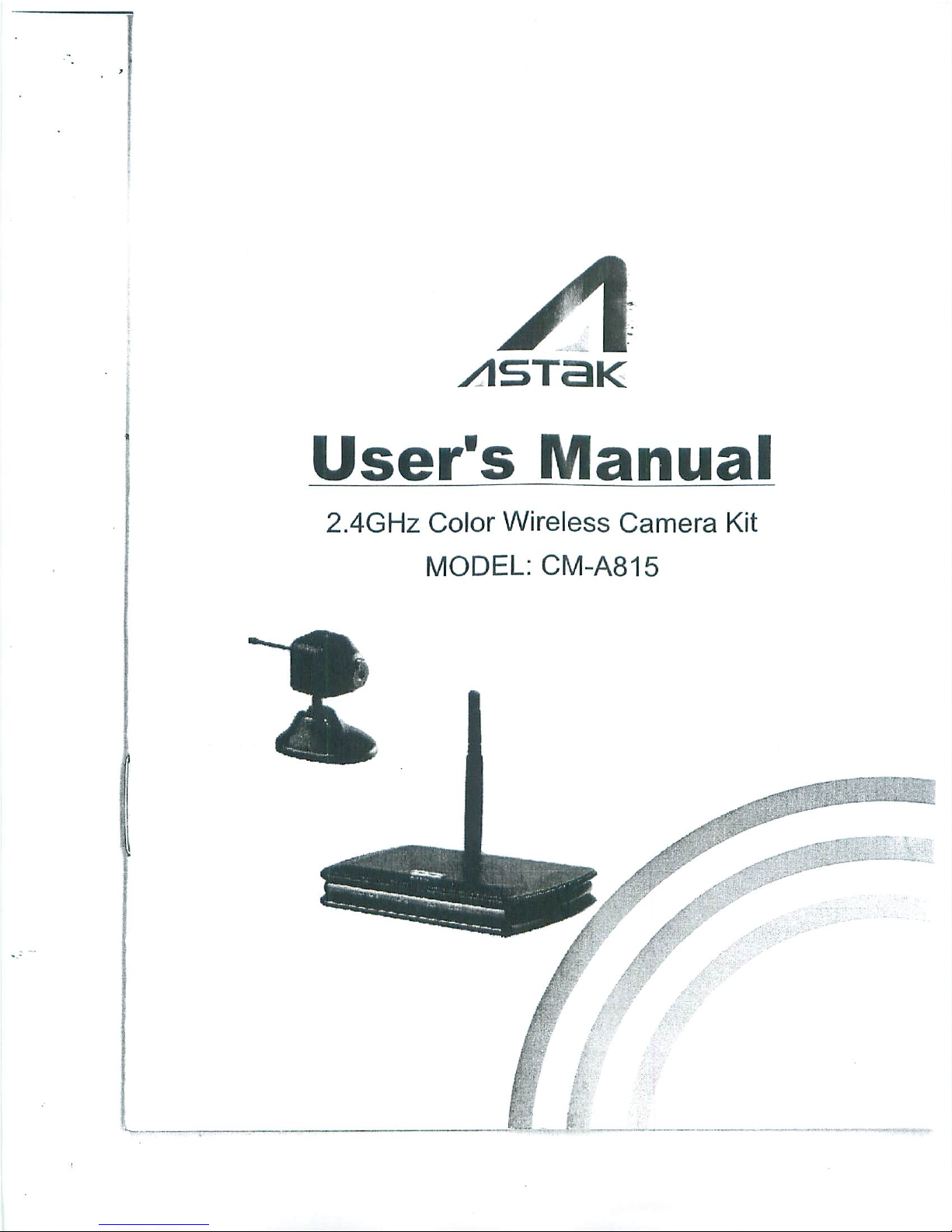
User's
Manual
2.4GHz
Color
Wireless
Camera
Kit
MODELCM-A815
Page 2
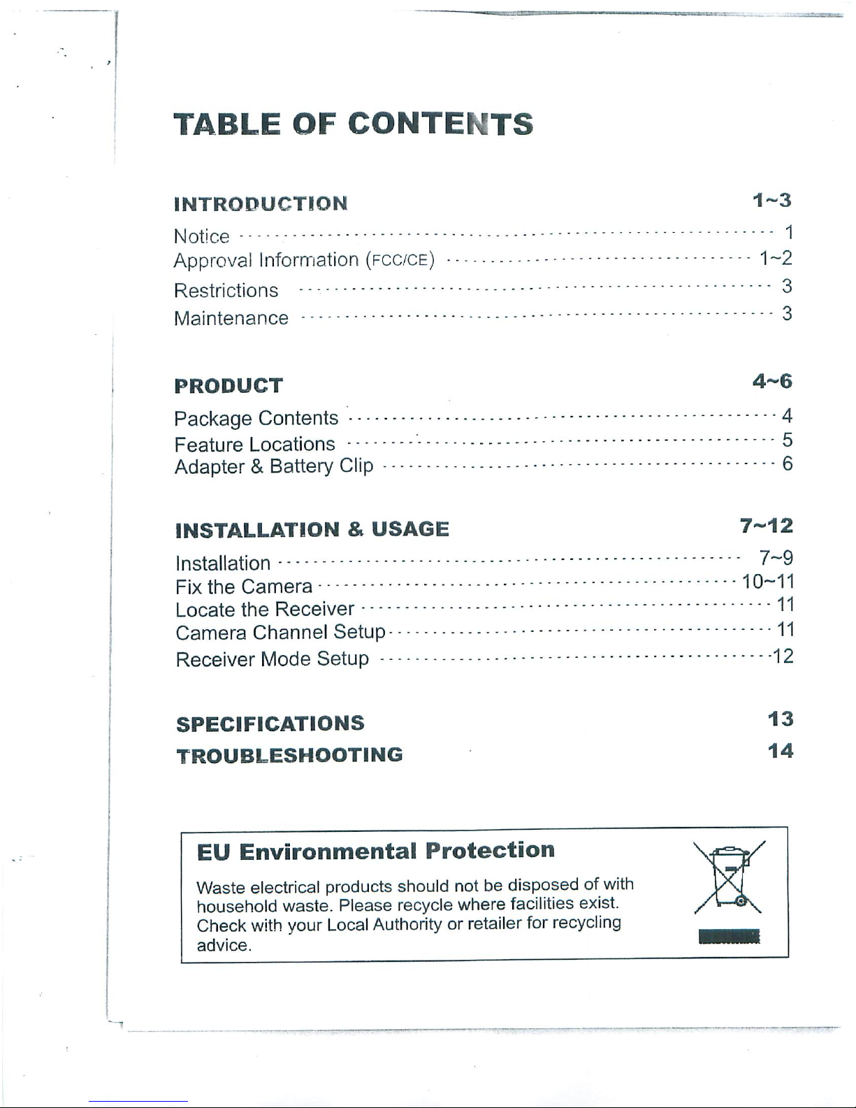
TABLE
OF
CONTENTS
INTRODUCTION
1-3
Notice
1
Approval
Information
(fcc/ce)
1-2
Restrictions
'3
Maintenance
"3
PRODUCT
4-6
Package
Contents
4
Feature
Locations
Adapter&Battery
Clip
6
INSTALLATION&USAGE
7-12
Installation
7~9
Fix
the
Camera
10-11
Locate
the
Receiver
"11
Camera
Channel
Setup
11
Receiver
Mode
Setup
12
SPECIFICATIONS
13
TROUBLESHOOTING
14
EU
Environmental
Protection
Waste
electrical
products
should
not
be
disposed
of
with
household
waste.
Please
recycle
where
facilities
exist.
Check
with
your
Local
Authority
or
retailer
for
recycling
advice.
Page 3
INTRODUCTION
Thank
you
for
your
interest
and
support
in
our
product
and
purchasing
this
wireless
camera
kit.
This
product
works
at
ISM-2.4GHz
frequency
band,
which
could
be
legally
used
worldwide
without
permission.
We
feel
confident
that
you
will
be
pleased
with
the
quality
and
features
of
this
product.
The camera
features
one
CMOS
image
sensor
andatransmitting
module
to
capture
the
image
and
transmit
them
wirelessly.
The
receiver features
a
receiving
module
to
receive
and
output
AV
signals.
Notice
Notice:
This
product
may
cause
interferences
with
other
wireless
equipment
that
operates
at
2.4GHz
ISM
band.
Please
turn
off
one
of
the
equipments
to
eliminate
the
interference.
Product
Assurance:
This
camera
will
emit
electromagnetic
wave,
just
like
other
wireless
products.
But
its
transmitting
power
is
less
than
other
wireless
products
such as
mobile
phones.
The
2.4GHz
wireless
camera
meets
wireless
frequency
security
standards
and
recommended
indexes
while
working.
These
standards
and
indexes
are
certificated
by
academic
organization
and
represent
the
cogitative
research
of
the
scientific
workers
who
continuously
explore
and
annotate
the
involved
fields.
So
we
believe
that
our
products
are
safe
for
customers.
Approval
Information
All
our
products
meet
the
requirements
of
approval
FCC
or
CE,
and
are
granted
the
FCC
or
CE
certification.
They
are
authorized
to
bear
FCC
or
CE
mark.
■
Page 4

FCC
This
equipment
has
been
tested
and
found
to
comply
with
the
limits
fora
ClassBdigital
device,
pursuant
to
Part
15
of
the
FCC
rules.
These
limits
are
designed
to
provide
reasonable
protection
against
harmful
interference
inaresidential
installation.
This
equipment
generates,
uses
and
can
radiate
radio
frequency
energy
and,
if
not
installed
and
used
in
accordance
with
the
instructions,
may
cause
harmful
interference
to
radio
communications.
However,
there
is
no
guarantee
that
interference
will
not
occur
inaparticular
installation.
If
this
equipment
does
cause
harmful
interference
to
radio
or
television
reception,
which
can
be
determined
by
turning
the
equipment
off
and
on,
the
user
is
encouraged
to
try
to
correct
the
interference
by
one
or
more
of
the
following
measures:
-Reorient
or
relocate
the
receiving
antenna.
-Increase
the
separation
between
the
equipment
and
the
receiver,
-Connect
the
equipment
into
an
outlet
onacircuit
different
from
that
to
which
the
receiver
is
connected.
-Consult
the
dealer
or
an
experienced
radio/TV
technician
for
help.
This
device
complies
with
Part
15
of
the
FCC
Rules.
Operation
is
subject
to
the
following
two
conditions:
(1)
This
device
may
not
cause
harmful
interference,
and
(2)
this
device
must
accept
any
interference
received,
including
interference
that
may
cause
undesired
operation
Changes
and
modification
not
expressly
approved
by
the
manufacturer
or
registrant
of
this
equipment can
void
your
authority
to
operate
this
equipment
under
Federal
Communications
Commissions
rules.
CE
This
product
complies
with
standards
including
Low
Voltage
Device
Directive
73/23/EEC;
EMC
Directive
89/336/EEC
and
R&TTE
Directive
1999/5/EC.
It
passed
the
subject
tests
by
the
authority
concerned
and
is
authorized
to
bear
CE
mark.
Page 5
Restrictions
1.
DO
NOT
use
this
product
to
violate
one's
privacy.
Monitoring
one's
activities
without
consent
is
illegal
and
this
product
is
not
designed
and
manufactured
for
such
purpose;
2.
DO NOT
put
this
product
near
any
medical
equipment.
Radio
waves
might
potentially
cause
breakdown
of
electrical
medical
equipment.
So
this
product
should
be
placed
at
least1feet
away
from
any
heart
pacemaker.
Radio
waves
might
potentially
influence
heart
pacemaker
and
lead
to
respiratory
disturbance;
3.
DO NOT
use
this
product
for
any
illegal
activities.
We
shall
not
be
responsible
for
any
consequences
of
illegal
acts
committed
by
the
user.
Maintenance
1.
Ensure
the
sufficient
ventilation
space
is
available;
2.
Do
not
shake
or
strike
the
product;
3.
Keep
it
dry
and
dustless
and
avoid
exposing
it
to
direct
sunlight;
4.
Do
not
place
product
near
any
magnetic
objects;
5.
Avoid
putting
the
product
in
places
where
the
constantly
changed
temperature
or
humidity
occurs;
6.
Keep
product
away
from
heat
sources
such
as
electric
heater;
7.
Do
not
use
the
camera
near
aggressive
chemicals;
8.
Do
not
use
this
camera
near
water,
for
example,
nearabath
tub,
wash
bowl,
kitchen
sink or
laundry
tub,
inawet
basement
or
near
a
swimming
pool
and
the
like;
9.
Do
not
use
the
camera
in
the
places
which
are
enclosed
by
metal.
The
surrounding
metal
like
lifter,
cabin,
may
shield
the
electromagnetic
wave,
and
result
in
failure
of
signal
reception;
10.
Please
obey
the
local
government's
environment
protection
policy;
11.
Please
turn
off
the
power
when
left
unused;
12.
Do
not
disassemble
or
repair
the
camera
or
receiver,
doing
so
might
cause
damages
to
the
product.
■ ■
Page 6

PRODUCT
Package
Contents
This
package
comes
with
the
following
items.
Please
check
whether
they
are
all
included
in
the
packaging
box,
if
one
or
some
is
missing,
contact
the
retailer
for
replacement.
(D Wireless
cameraX1
Wireless
receiver
X1
Antenna
for
receiverx1
Holder
for
receiverx1
Mounting
plate
for
camerax1
©
DC
8.0V
power
adapter
for
camerax1
(7)
DC
8.0V
power
adapter
for
receiverx1
®AV
cable
X1
(9)
Lens
adjuster
X1
®
Channel
pick
for
camerax1
©
Mounting
screwx1
@
Foam
base
for
camera
X1
@
User's
manualx1
®
Battery
clip
X1
Note:
1.
This
product
canbeeither
black or
silver.
2.
The
pictures
may
vary
from
the
actual
objects.
J
#-<
\\
*
a.
Page 7

Feature
Locations
1-
Camera
1
■
Antenna
Channel
Switch
Cover
Microphone
DC
Power
Jack
2.
Receiver
Antenna
AV
Output
DC
Power
Jack
Mode
Control
Lens
Universal
Bracket
Channel
Indicator
Channel
Select/Mode
Switch
Button
~_
Page 8

Adapter
This
product
always
conforms
to
the
authenticated
AC
adapter.
The
adapter
should
be
marked one
of
the
following:
UL
Mark
American
power
supply
authentication
CE
Mark
European
Union
power
supply
authentication
SAA
Mark
Australia
power
supply
authentication
PSE
Mark
Japan
power
supply
authentication
GS
Mark
German
power
supply
authentication
CCC
Mark
China
power
supply
authentication
Note:
When
using
the
power
adapter,
make
sure
the
rating
voltage
on
it
is
compatible
with
that
of
the
device
to
avoid
potential
damages
resulting
from
incorrect
usage
of
power
supply.
Battery
Clip
With
the
supplied
battery
clip,
the
camera
could
be
powered
by
battery
of
the
same
voltage
for
temporary
use.
Camera
Battery
Clip
Battery
Page 9

INSTALLATION&USAGE
Installation
1.
Connect
the
power
jack
of
adapter
(DC
8.0V
300mA)
or
battery
with battery
clip
to
camera.
a.
Connect
with
adapter
b.
Connect
with
battery
clip
2.
Connect
the
antenna
to
the
receiver.
3.
Connect
the
receiver
to
the
monitor/TV
with
AV
cable.
(Red
socket
for
audio;
yellow
socket
for
video).
Turn
on
the
monitor/TV
and
select
AV
mode.
L-,
._-_
.
„
Page 10

4.
Connect
the
power
jack
of
adapter
(DC
8.0V
300mA)
to
receiver.
Slide
Mode
Control
switch
toMposition
and
the
channel
indicator
lights
up
green.
Note:
The
receiver
provides
Power
Off
(OFF)
mode,
Manual
mode
(M)
and
Channel
Scan
mode
(L).
Please
refer
to
Receiver
Mode
Setup
section
on
page12for
more
details.
5.
Open
the
channel
switch
cover
and
set
the
camera
to
one
desired
channel.
Default
Setting
Notes:
Please
refer
to
Camera
Channel
Setup
section
on
page
11 for
more
details.
Please
recover
the
channel
switch
after
finished
setting.
6.
Press
the
channel
select
"SELECT"
button
on
the
receiver
until
the
channel
indicator
matches
to
the
channel
on
the
corresponding
camera,
and
the
monitor/TV
will
display
pictures.
Channel
Select Button
8
Page 11

7.
If
the
picture
is
blur,
you
could
adjust
the
lens
focus
with
lens
adjuster
to
make
the
picture
clear.
Lens
Adjuster
8.
Mount
the
camera
toadesired
location.
\
/
Paste
the
foam
base
on
the
bottom
Paste
the
camera
on
the
desktop
Paste
the
camera
on
the
wall
Notes:
You
can
paste
the
foam
base
on
the
bottom
of
the
Universal
Bracket
to
fix
the
camera.
When
you
fix
the
camera
with
the
mounting
plate,
the
foam
base
can
not
be
pasted
on
the
bottom
of
the
Universal
Bracket
Please
refer
to
Fix
the
Camera
section
on
page
10
for
more
details
to
fix
the
camera
with
the
mounting
plate.
9.
Adjust
the
brightness,
contrast
and
color
setting
of
the
monitor/TV
to
get
the
best
display
effect.
..
_
Page 12

Fix
the
Camera
Please
follow
the
steps
below
if
you
want
to
fix
the
camera
to
wall
or
ceiling.
1.
Fix
to
Wall
1.1
Drill
one
hole
on
the
mounting
surface,
insert
the
anchor
into
the
hole,
then
align
the
mounting
plate
with
the
hole
you
just
drilled
and
drive
the
screw
through
the
plate
into
the
anchor;
1.2
Hang
the
camera
on
the
hooks
of
mounting
plate;
1.3
Push
downwards
the
camera
firmly.
2.
Fix to
Ceiling
2.1
Detach
the
universal
bracket
from
the
camera
and
then
install
it
to
the
camera
top
for
avoiding
reverse
picture;
2.2
Secure
the
mounting
plate
to
ceiling
with
screw;
2.3
Hang
the
camera
on
the
hooks
of
mounting
plate;
2.4
Push
the
camera
firmly
as
the
shown
direction.
/
2.1
Rotate
Bracket
90°
to
separateitfrom
bottom
Rotate
Bracket
90°
to firmiton
the top
of
camera
10
Page 13

•
*=■
1
Mounting
Plate
2.2
Hook
J
V
Locate
the
Receiver
The
receiver
can
be
placed
horizontally
or
vertically.
When
it
is
placed
vertically,
the
supplied
holder
is
required.
Holder
Horizontal
Vertical
Camera
Channel
Setup
This
camera
has4selectable
channels
to
avoid
possible
interference
from
other
nearby
wireless devices.
Please
open
the
channel
switch
cover
and
set
the
Channel
Switch
as
the
following
diagram.
Default
Setting
Channel
Frequency
f
1
2
Channel
Switch
CH1sCH2
Setup
Diagram
CH3
CH4
_
~
5
CH1=2,414MHz;
CH2=2p432MHz;
CH3=2,450MHz;
CH4=2,468MHz
11
....
■.—■
...
Page 14

Receiver
Mode
Setup
The
receiver
can
support
up
to4cameras
working
at
the
same
time.
It
provides
Power
Off
mode
(OFF),
Manual
mode
(M)
and
Channel
Scan
mode
(L).
1.
Power
Off
mode:
Slide
Mode
Control
switch
to
OFF
to
power
the
receiver
off;
OFF-M-L
2.
Manual
mode:
Slide
Mode
Control
switch
toMto
enter
Manual
mode.
In
manual
mode,
the
receiver
channel
won't
change
until
you
press
the
Channel
Select
button;
OFF-M-L
3.
Channel
Scan
mode:
Slide
Mode
Control
switch
toLto
enter
channel
scan
mode.
In
channel
scan
mode,
all
the
channels
will
display
one
by
one
looping
in
turn
per
5s.
Slide
the
Mode
Control
switch
toMor
OFF
to
exit.
Tip:
At
the
manual
mode,
you
could
press
and
hold
the
Channel
Select
"SELECT"
button
more
than
5s
to
enter
the
channel
scan
mode.
Press
the
button
againtoexit.
CH2
CH1
CH3
Channel
Scan
Mode
CH3
i
CH4
12
Page 15

SPECIFICATIONS
Items
Transmission
Frequency
Antenna
Type
Transmission
Distance
Operating
Temperature
Storage
Temperature
Storage
Humidity
Imaging
Sensor
CMOS
Total
Pixels
S/N
Ratio
Horizontal
Resolution
Minimum
Illumination
Transmission
Power
Power
Supply
Consumption
Current
Dimensions
(WxDxH)
Weight
Receiving
Sensitivity
Power
Supply
Consumption
Current
Video
Output
Level
Audio
Output
Level
Dimensions
(WxDxH)
Weight
Value
ISM2,400MHz~2,483MHz
Omni
100m
(Without
Block)
-10°C~+50DC/+14oF~+122°F
-20cC~+60°C/-4DF~+140°F
^85%
RH
CMOS
628x582(PAL)/
510x492(NTSC)
40dB
(AGC
OFF)
380TVLines
5 Lux/Ft
.2
10mW(CE)/2mW(FCC)
DC
8.0V
300mA
90
mA
(Max.)
23mmx31mmx23mm
(Main
Body)
Approx.20g
(Main
Body)
-85dBm
DC
8.0V
300mA
240mA
(Max.)
1VP.P@75Q
1Vp.p@10kQ
100mmx70mmx18mm
(Main
Body)
Approx.
99g
(Main
Body)
Specifications
are
subject
to
minor
change
without
prior
notice.
13
Page 16

TROUBLESHOOTING
When
you
experience
the
operation
problems,
please
check
and
try
the
following
yourself
before
claiming
that
it
is
the
defective
product
or
consulting
the
experienced
technician.
Abnormal
Phenomena
Possible
Reasons/Solutions
No
image
No
sound
Check
whether
the
camera/receiver
is
connected
to
power
supply
and
powered
on.
Snowflakes
on
image
Noisy
1.
Check
if
the
channel
of
receiver
is
the
same
as
that
of
camera;
2.
Check
the
distance&blocks.
Blur
image
Adjust
the
lens
of
camera.
Normal
sound
Ghost
image
1,
Interfered with
other
devices;
2.
Check
the
distance&blocks.
Normal
sound
No
color
Mismatching
the
TV
system
of
PAL
or
NTSC.
Normal
sound
Interfered
with
other
devices
nearby;
Remove
or
turn
off
such
devices.
Normal
image
Noisy
—,
....
 Loading...