

Page 1
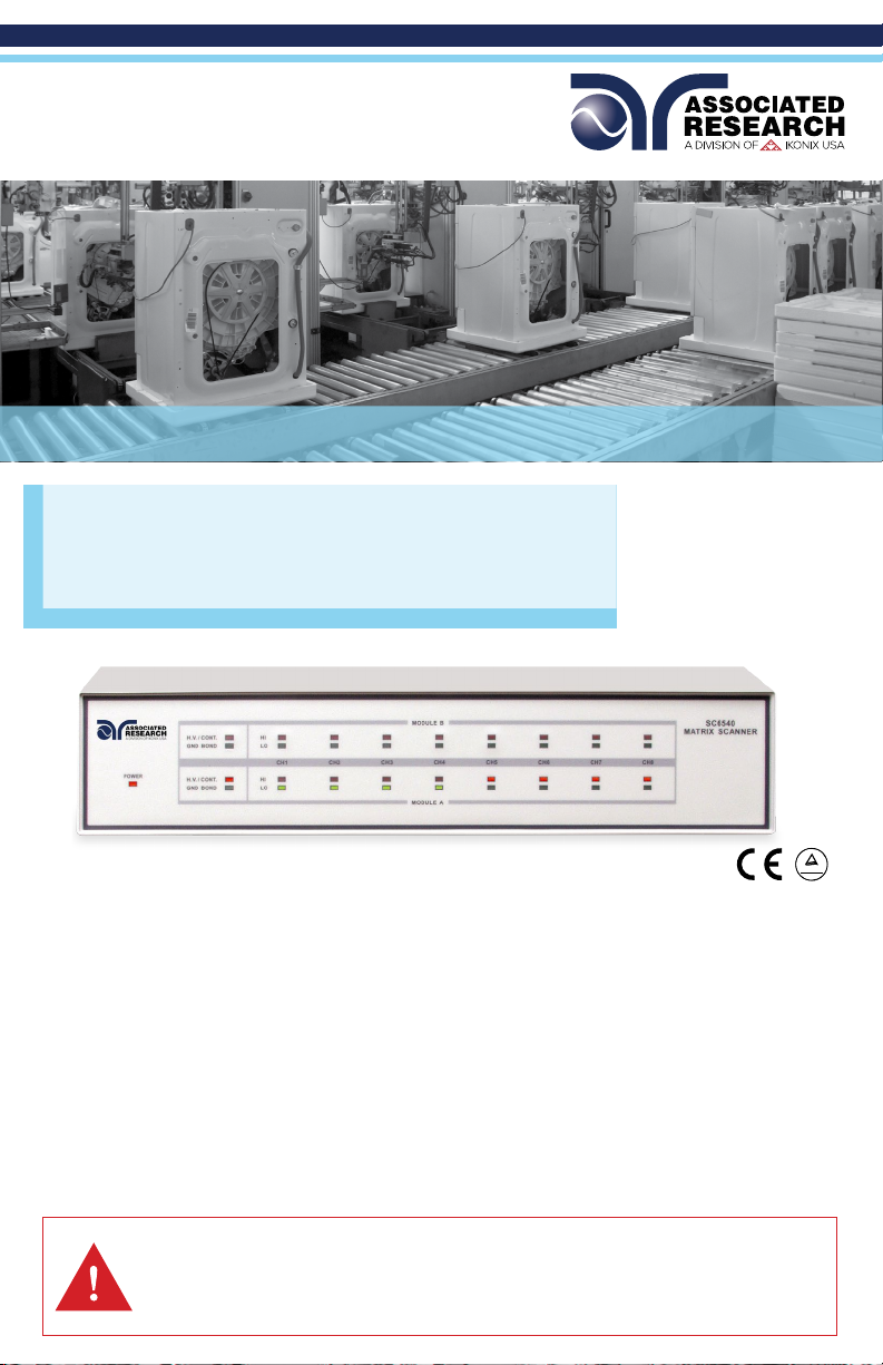
Quick Start Guide
C
US
SC6540
Model SC6540
SAFETY CHECKLIST
Survey the test station. Make sure it is safe & orderly.
Always keep unqualied/unauthorized personnel away from the test area.
Familiarize yourself with safety protocols in the event of a problem.
Exercise caution and never touch products or connections during a test.
TÜV Rheinland
Train operators. Never touch clips directly and always connect the return lead rst.
You should always know when a test is being performed.
WARNIN G: THIS GUIDE WA S CREATED FOR O PERATORS HAVING S OME FAMILI ARITY W ITH ELECTR ICAL SAF ETY
TESTING. AN ELECTRICAL SAFETY TESTER PRODUCES VOLTAGES AND CURRENTS THAT CAN CAUSE HARMFUL
OR FATAL ELECTRI C SHOCK. TO PRE VENT ACCIDENTAL I NJURY OR DE AT H, THESE SAFE TY PROCED URES MUST
BE STRI CTLY OBSERVED WHEN HANDLING AN D USING A TEST INS TRUMENT. CONTACT US AT
INFO@ARISAFET Y.COM FOR MORE INFO ON HOW TO GET TR AINED ON ELECT RICAL SAFE TY TESTIN G.
Page 2
FRONT PANEL CONTROLS
3
1 2
1
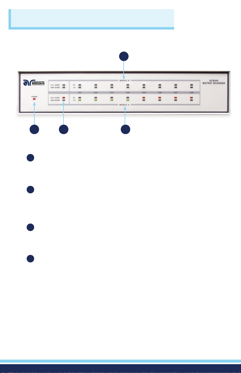
POWER INDICATOR: Indicates the power has been turned ON. For a
SC6540 Master, this lights up when the power switch on the rear panel of the
unit is turned ON. For a SC6540 Slave, this lights up when the power switch
on the host instrument is turned ON.
MODULE TYPE INDICATOR: These LED’s indicate the type of module that
2
is installed for the corresponding module slot. If the red LED illuminates, it
indicates that the installed module is a High Voltage/Continuity module. If
the green LED illuminates, it indicates that the installed module is a Ground
Bond module.
MODULE B CHANNEL STATUS INDICATORS: These LED’s indicate the
3
status of each individual channel on Module B. If the red LED illuminates, it
indicates a High Voltage/Continuity Current/Ground Bond channel. If the
green LED illuminates, it indicates a Return channel.
MODULE A CHANNEL STATUS INDICATORS: These LED’s indicate the
4
status of each individual channel on Module A. If the red LED illuminates,
it indicates a High Voltage/Continuity Current/Ground Bond channel. If the
green LED illuminates, it indicates a Return channel.
4
2
Page 3
BACK PANEL CONTROLS
1 2 3 4
5 6
1
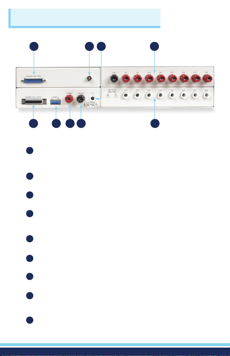
SCANNER BUS INPUT: Interconnect port for the control cable between
the SC6540 slave and an automated Associated Research electrical safety
tester or SC6540 master Scanner.
SAFETY GROUND CONNECTOR: Must be connected to a known good
2
ground system to ensure operator safety.
HIGH VOLTAGE INPUT: Connector for input of high voltage from the host
3
instrument.
GROUND BOND OUTPUTS: Output channels for application of high
4
current for Ground Bond tests. These outputs are only available on SC6540
Scanners that are congured with a Ground Bond Module.
SCANNER BUS OUTPUT: Interconnect port for the control cable to
5
another SC6540 in a multiple SC6540 system.
ADDRESS SWITCHES: 8-pin DIP switch used to address the modules in a
6
SC6540 slave or used to congure the address of a SC6540 master.
CURRENT INPUT JACK: Connector used to attach the high current input
7
lead or Continuity Current input lead from the host instrument.
7 8 9
(Slave Scanner, HGS, Back Panel)
RETURN INPUT: Connector for the return of the host instrument with the
8
SC6540. This connection provides the Return Current path for the High
Voltage, Ground Bond Current, and Continuity Current.
9
HIGH VOLTAGE OUTPUTS: Eight individual output channels for High
Voltage tests and Continuity tests. These outputs are only available on
SC6540 Scanners that are congured with a High Voltage Module.
3
Page 4
BACK PANEL CONTROLS
1 2
1
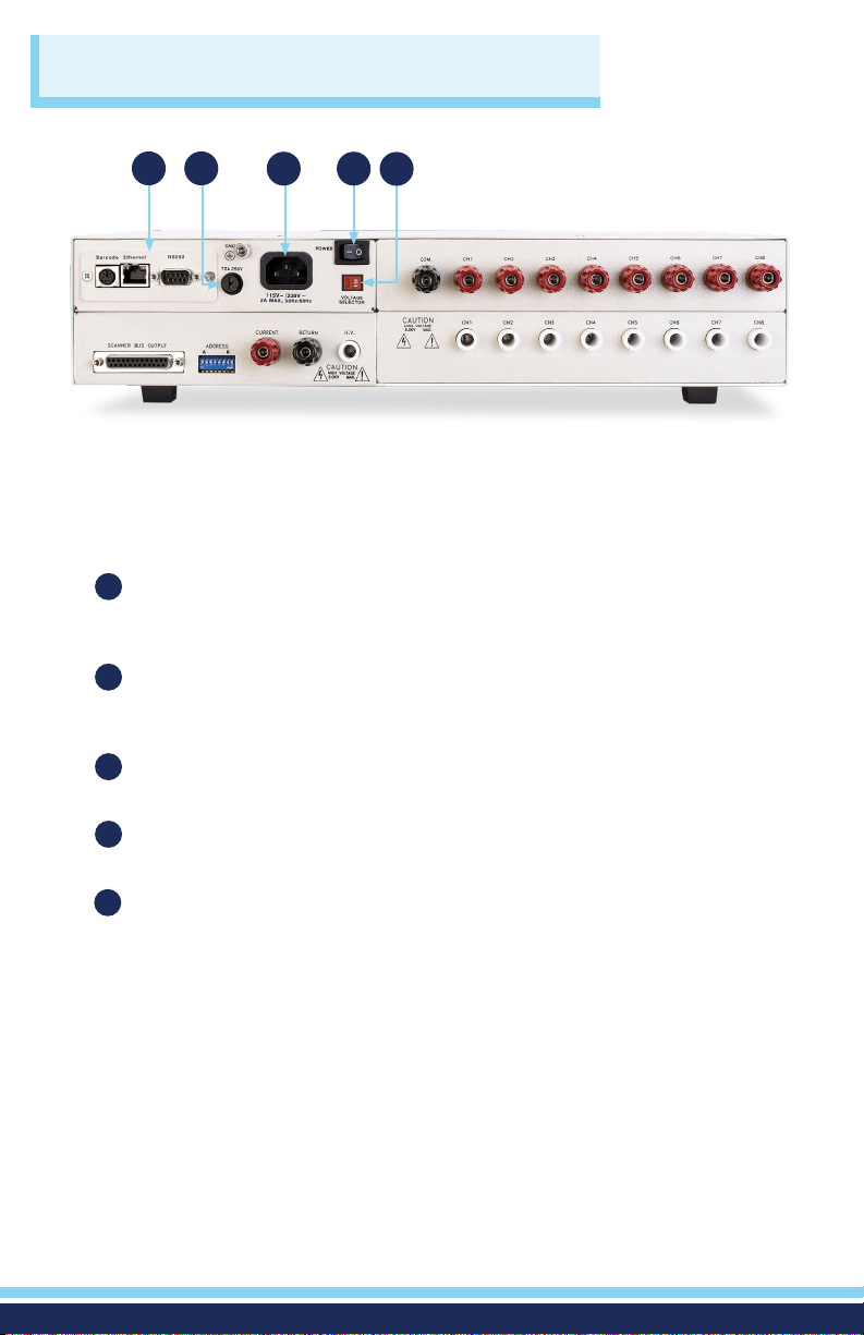
BUS INTERFACE: Standard connector for interconnection to the USB/RS-232
Bus interface. Optional IEEE-488 interface or Ethernet Interface may be
substituted for the USB/RS-232.
FUSE RECEPTACLE: To change the fuse, unplug the power (mains) cord and
2
turn the fuse receptacle counter-clockwise. The fuse compartment will be
exposed. Replace the fuse with one of the proper rating.
INPUT POWER RECEPTACLE: Standard IEC 320 connector for a standard
3
NEMA style line power (mains) cord.
3 4 5
(Master Scanner, HGM, Back Panel)
POWER SWITCH: Rocker style power switch with international ON ( | ) and
4
OFF (0) markings.
INPUT VOLTAGE SWITCH: Line voltage selection is set by the position of the
5
switch. In the “left” position it is set for 110–120 volt operation, in the “right”
position it is set for 220–240 volt operation.
4
Page 5
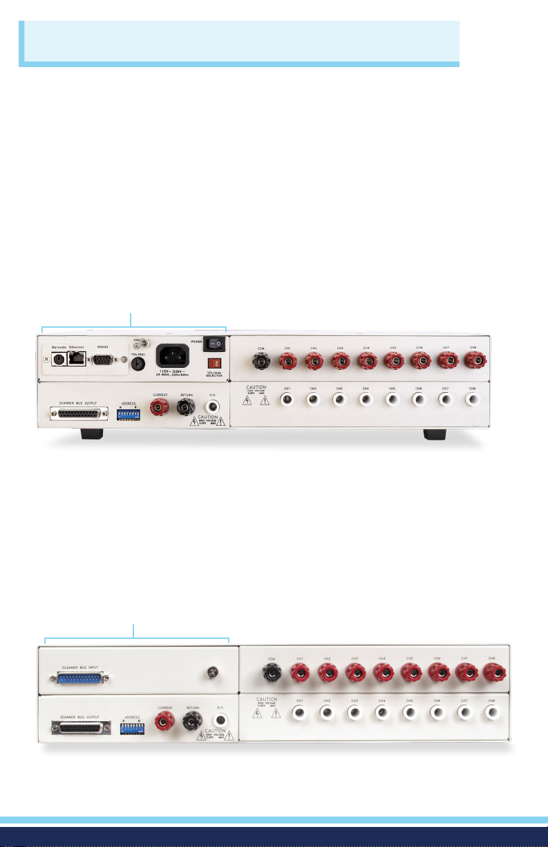
SCANNING CONFIGURATIONS
The SC6540 is available in two basic congurations according to how it sends
and/or receives data: a master and a slave. A master Scanner can only be
controlled remotely via a PC. A slave Scanner can be controlled locally by an
Associated Research testing instrument or by a master Scanner.
MASTER
A master Scanner communicates directly with a PC via a USB/RS-232 (standard),
GPIB interface, or Ethernet. This model receives control information from a PC
and can also deliver instructions to up to four additional slave Scanners. A master
Scanner can be distinguished by its power module located on the upper left side
of the rear panel.
POWER MODULE
SLAVE
A slave Scanner only receives data. The data that the slave receives can come
from a master Scanner (remote control) or directly from an Associated Research
instrument (local control). A slave Scanner can be distinguished by its input
control bus located on the upper left side of the rear panel.
INPUT CONTROL BUS
5
Page 6
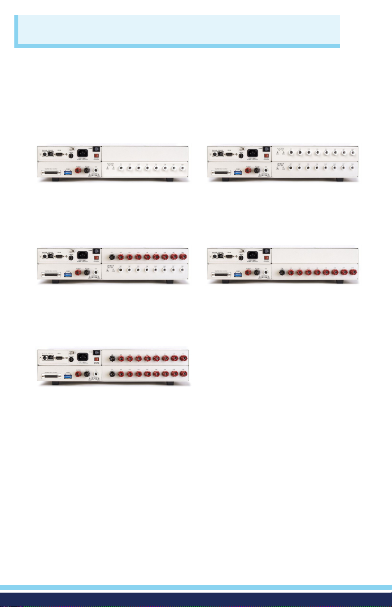
BACK PANEL CONFIGURATIONS
The modular design allows for a variety of congurations. In addition to master
or slave congurations, the scanners can also be set-up with the following
congurations: 8 or 16 High Voltage testing channels, 8 High Voltage and Ground
Bond testing channels, and 8 or 16 Ground Bond testing channels.
Model SC6540 HNM
8 Channel High Voltage Scanner
Model SC6540 HGM
8 Channel High Current Scanner
8 Channel High Voltage Scanner
Model SC6540 GGM
16 Channel High Current Scanner
*Also available in slave congurations
Model SC6540 HHM
16 Channel High Voltage Scanner
Model SC6540 GNM
8 Channel High Current Scanner
The different congurations (shown right)
are indicated by the following alpha
designators.
M = Master Scanner
H = 8 High Voltage Channels
HH = 16 High Voltage Channels
G = 8 Ground Bond Channels
GG = 16 Ground Bond Channels
N = Empty Module
S = Slave
6
Page 7

CONNECTIONS
WARNING: UNDER CERTAIN CONDITIONS HIGH VOLTAGE CAN APPEAR ON THE CABINET
OF THE SC6540. THE GROUND TERMINAL ON THE REAR PANEL OF THE SC6540 MUST BE
CONNECTED TO A GOOD EARTH GROUND TO ENSURE OPERATOR SAFETY.
CAUTION: MULTIPLE HIGH VOLTAGE OR CONTINUITY CURRENT CHANNELS CAN BE SET TO
ACTIVATE SIMULTANEOUSLY. HOWEVER, WHEN CONFIGURED THIS WAY THE SC6540 CANNOT
PROVIDE AN INDICATION OF WHICH OUTPUT DETECTED FAILURE. THEREFORE, EACH ITEM
OR TEST POINT WOULD HAVE TO BE RE-TESTED INDIVIDUALLY IF THE OPERATOR NEEDS TO
DETERMINE THE EXACT POINT OF FAILURE.
OPERATING THE SC6540 WITH HYPOTULTRA
HypotULTRA
CURRENT SENSE+
CAUTION
HIGH VOLTAGE
5KVAC MAX.
6KVDC MAX.
RS232Barcode Ethernet
SCANNER BUS OUTPUT ADDRESS
HIGH VOLTAGE
ON
CURRENT SENSE+
CAUTION
5KVAC MAX.
6KVDC MAX.
SENSE-RETURN
A B
1 2 3 4 5 67 8
SENSE-RETURN
GND
T2A 250V
2AMAX., 50Hz / 60Hz
CURRENT
SCANNER 2 SCANNER 1
REMOTE INTERFACE
SIGNAL OUTPUT
POWER
115V ~/ 250V ~
RETURN
CAUTION
HIGH VOLTAGE
5.0 KY MAX.
SCANNER 2 SCANNER 1
REMOTE INTERFACE
SIGNAL OUTPUT
SCANNEROUTPUT
SIGNAL INPUT
CAL.
SC6540 Master
COM.
115
VOLTAGE
SELECTOR
CAUTION
HIGH VOLTAGE
5.0 KY MAX.
H.V.
HypotULTRA
SCANNEROUTPUT
SIGNAL INPUT
CAL.
GND
100-120~/200-240V~
700VA MAX., 50Hz/60Hz
CH1 CH2 CH3 CH4 CH5 CH6 CH7 CH8
CH1
CH2 CH3 CH4 CH5 CH6 CH7 CH8
GND
®
RS232
INPUT
RS232
INPUT
100-120~/200-240V~
700VA MAX., 50Hz/60Hz
T6.3A 250V
To PC
T6.3A 250V
SCANNER BUS INPUT
SCANNER BUS OUTPUT ADDRESS
ON
A B
1 2 3 4 5 67 8
CURRENT
RETURN
CAUTION
HIGH VOLTAGE
5.0 KY MAX.
SC6540 Slave
COM.
CAUTION
HIGH VOLTAGE
5.0 KY MAX.
H.V.
7
CH2 CH3 CH4 CH5 CH6 CH7 CH8
CH1
CH2 CH3 CH4 CH5 CH6 CH7 CH8
CH1
Page 8
CONNECTIONS
OPERATING THE SC6540 WITH HYPOTULTRA (Continued)
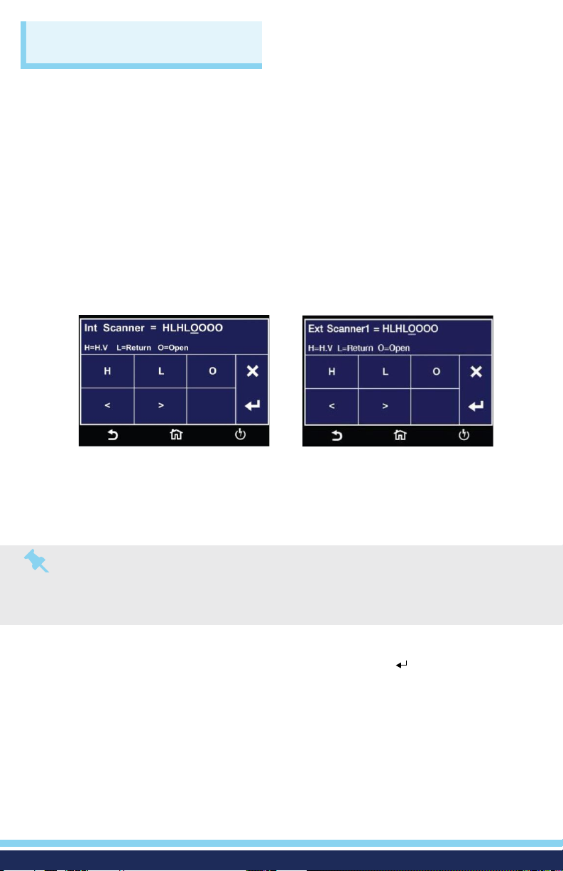
SETUP
The SC6540 Scanner channels can be set as High (H) for High Voltage or Continuity
testing output, Low (L) for the Return connection, or Open (O) for OFF. Channel
setup is done using the HypotULTRA menu or accompanying automation software.
For information on SC6540 setup through Associated Research’s Autoware® 3
Automation Software, consult the Autoware® 3 help le.
The following setup procedure will refer to setup through the HypotULTRA setup
menu: from the Test Parameter Review screen (ACW, DCW, CONT, or IR) you can
scroll to nd the Scanner settings. Below is an example of the ACW Withstand Test
Parameter Review screen.
The above images show a HypotULTRA with 8 Internal Scanner channels and 8
external channels. The “Int Scanner” parameter in the menu pertains to an internal
8-channel Scanner and the “ExtScanner1” parameter pertains to an 8-channel high
voltage SC6540 Scanner.
Note: Each Scanner port on the rear panel of the HypotULTRA can only control 8 channels
of each type (HV or HC) at a time, which makes it possible to control a maximum total of 16
possible external Scanner channels. To control more than 16 external channels, automation
software must be used along with a SC6540 Master and a PC.
To set the Scanner channels use the back (<) and forward (>) arrows and set the
channels to High (H), Low (L) or Open (O). Use the enter key ( ) to save the values
and move on to the next test parameter.
H (High) – High voltage output channel for a high voltage test or current output for a
continuity test.
L (Low) – High voltage return channel for a high voltage test or a current return for a
continuity test.
O (Open) – Channel is neither an output nor a return.
8
Page 9
CONNECTIONS
OPERATING THE SC6540 WITH HYPOTULTRA (Continued)
OPERATION
Once the SC6540 is incorporated into a test system, it will act as an extension of
the HypotULTRA. The outputs will only activate while a test is being performed
and will deactivate when the test is not running. When a failure is detected, the
test will stop, the output will be deactivated and the HypotULTRA will give a
visual and audible indication of failure. If steps were connected in sequence, the
HypotULTRA will indicate a failure once it reaches the output that is connected
to the defective device. The SC6540 will not continue to test the other outputs
until the RESET button is pressed, the defective item is removed, and the TEST
switch is pressed once again. The SC6540 will then begin to test from the rst
step in the program.
Slave Scanner Power
Once the SC6540 slave is connected to the HypotULTRA, the “power on” LED
will light up as soon as the power switch of the HypotULTRA is turned on.
Master Scanner Power
The SC6540 master is powered on by ipping the switch on the rear panel of the
unit to the ON position. The SC6540 Scanner channels will activate when the
TEST signal is sent via a PC.
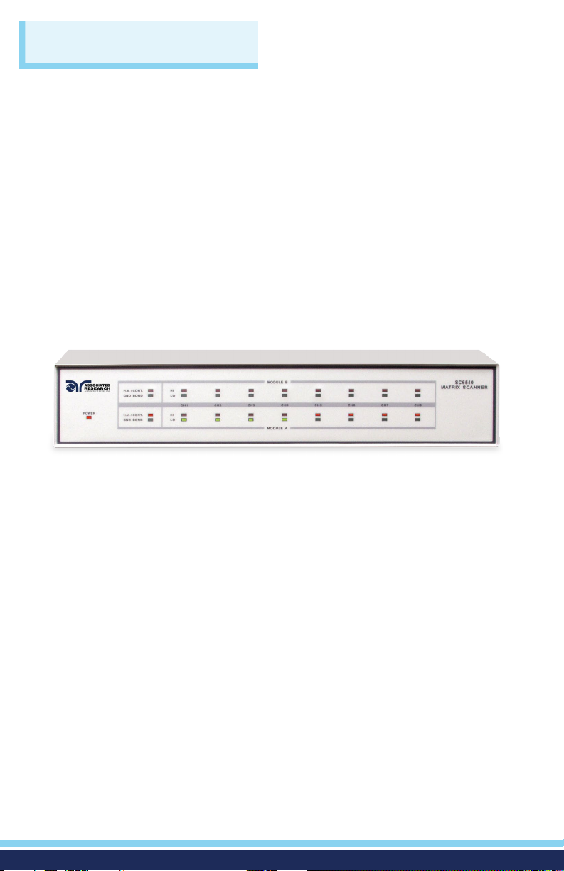
LED Indicators
During a test, individual LED indicators for each output indicate whether the
output is set as High, Low, or Open. If the channel is set as a High Voltage
Output or Continuity Current Output, the red LED will light up. If the channel is
set as Return, the green LED will light up. If the High Voltage channel is set to
Open, no LED will light up.
9
Page 10
CONNECTIONS
OMNIA II
SENSE+
H.V.
SENSE
-
CURRENT
RETURN
SIGNAL INPUT
SIGNAL OUTPUTSCANNER 1 SCANNER 2
RS232
T10A 250V
GND
CAT. II
115V~ /230V~
10A MAX., 50Hz/60HZ
CAUTION
HIGH VOLTAGE
5KV MAX.
CAUTION
HIGH VOLTAGE
5KV MAX.
GROUND
TEST
OUTPUT
CH
H.V.
TEST
OUTPUT
OUTPUT
REMOTE INTERFACE
INPUT
G-COM. CH1 CH2 CH3 CH4 CH5 CH6 CH7 CH8
RETURN
COM.
POWER
SCANNER BUS OUTPUT ADDRESS
A B
RS232Barcode Ethernet
GND
T2A 250V
VOLTAGE
SELECTOR
115V ~/ 250V ~
2AMAX., 50Hz / 60Hz
CH1
H.V.
CH2 CH3 CH4 CH5 CH6 CH7 CH8
CAUTION
HIGH VOLTAGE
5.0 KY MAX.
CAUTION
HIGH VOLTAGE
5.0 KY MAX.
CURRENT
CH1 CH2 CH3 CH4 CH5 CH6 CH7 CH8
115
1 2 3 4 5 6 7 8
ON
SC6540 Master
To PC
OPERATING THE SC6540 WITH OMNIA II® 8204
GROUND BOND CONNECTIONS
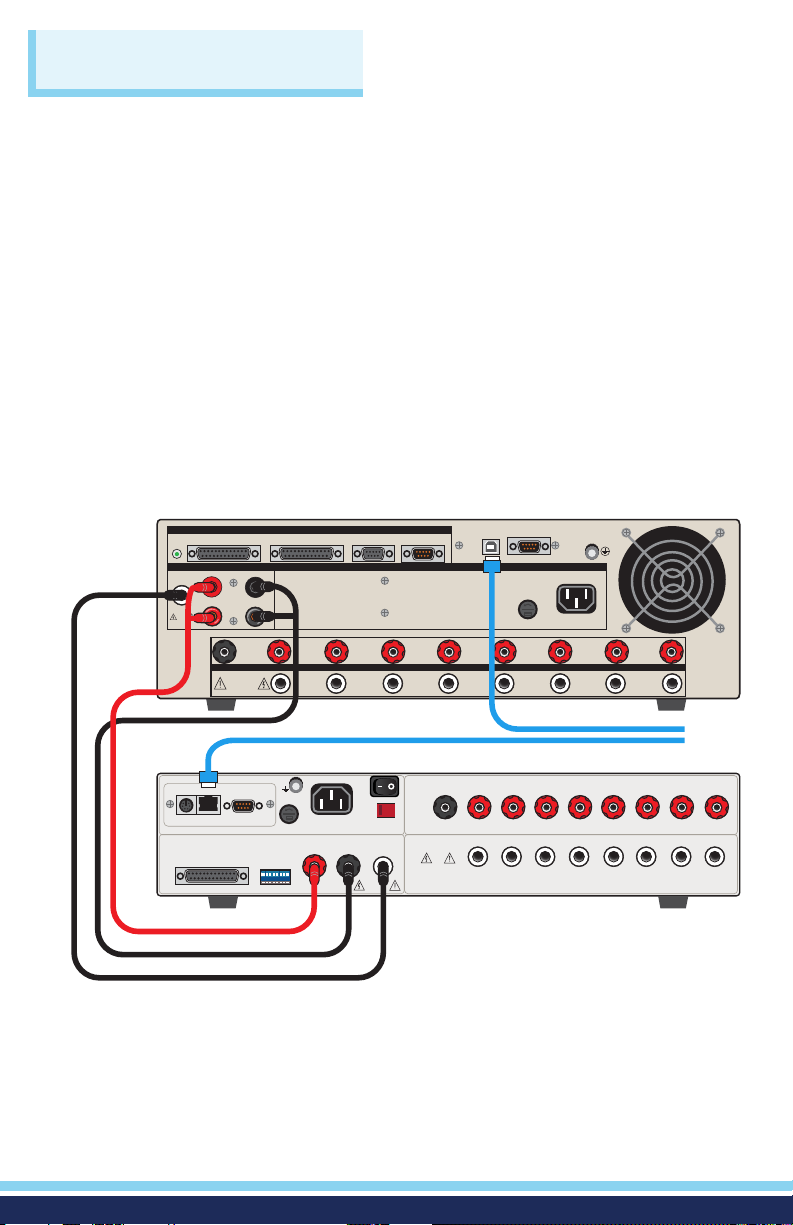
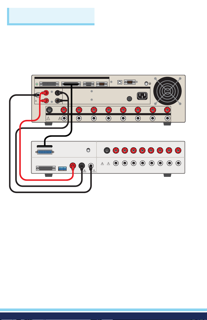
The rear panel of the SC6540 can include up to 16 output terminals for Ground Bond
testing if this conguration is selected at the time of purchase. *We recommend using
standard 12 gauge wire for operation at 30 amps, and 10 gauge wire for 40 amps.
The wires should be attached using the hook-style crimp lugs provided, to minimize
connection resistance. The Kelvin connection of an Associated Research Ground
Bond tester will end at the Ground Bond input terminals of the SC6540 Scanner. For
this reason, the wire lengths going from the SC6540 High Current output and the
High Current Return should be kept as short as possible to limit the effect of test lead
resistance.
10
Page 11
CONNECTIONS
SCANNER BUS INPUT
RETURN
SCANNER BUS OUTPUT ADDRESS
A B
CH1
H.V.
CH2 CH3 CH4 CH5 CH6 CH7 CH8
CAUTION
HIGH VOLTAGE
5.0 KY MAX.
CAUTION
HIGH VOLTAGE
5.0 KY MAX.
CURRENT
1 2 3 4 5 6 7 8
ON
SC6540 Slave
OMNIA II
SENSE+
H.V.
SENSE
-
CURRENT
RETURN
SIGNAL INPUT
SIGNAL OUTPUTSCANNER 1 SCANNER 2
RS232
T10A 250V
GND
CAT. II
115V~ /230V~
10A MAX., 50Hz/60HZ
CAUTION
HIGH VOLTAGE
5KV MAX.
CAUTION
HIGH VOLTAGE
5KV MAX.
GROUND
TEST
OUTPUT
CH
H.V.
TEST
OUTPUT
OUTPUT
REMOTE INTERFACE
INPUT
G-COM. CH1 CH2 CH3 CH4 CH5 CH6 CH7 CH8
COM.
CH1
CH2 CH3 CH4 CH5 CH6 CH7 CH8
OPERATING THE SC6540 WITH OMNIA II 8204 (Continued)
GROUND BOND CONNECTIONS
11
Page 12
CONNECTIONS
OPERATING THE SC6540 WITH OMNIA II 8204 (Continued)
SETUP
The SC6540 Scanner channels can be set as High (H) for High Voltage or Continuity
testing output, Low (L) for the Return connection, or Open (O) for OFF. Channel
setup is done using the OMNIA II menu or accompanying automation software.
For information on the SC6540 setup through Associated Research’s Autoware®
Automation Software, consult the Autoware® 3 help le.
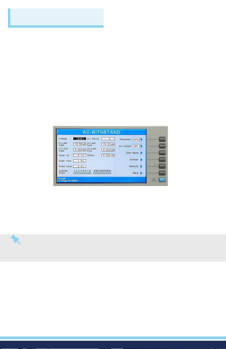
The following setup procedure will refer to setup through the OMNIA II setup menu:
in the Setup Test Parameters screen (ACW, DCW, IR, Ground Bond or Continuity)
you will nd the Scanner settings. Below is an example of the ACW Withstand Test
Setup Menu.
The above menu shows an OMNIA II connected to a 16-channel Scanner
conguration. This conguration can be one external 16-channel Scanner (8
high voltage ports and 8 high current ports) or two external 8-channel Scanners.
With two external 8-channel Scanners, one Scanner should be connected to
the Scanner 1 connector on the rear panel of OMNIA II and the second Scanner
should be connected to the Scanner 2 connector on the rear panel of OMNIA II.
Note: Each Scanner port on the rear panel of the OMNIA II can only control 8 channels
of each type (HV or HC) at a time, which makes it possible to control a maximum total
of 16 possible external Scanner channels. To control more than 16 external channels,
automation software must be used along with a SC6540 Master and a PC.
Navigate the Test Setup screen using the arrow keys, located on the OMNIA II
keypad, until you reach the Scanner Setup parameters. The Scanner channels can
be set using the “Scanner Select” soft key located to the right of the LCD display.
The Scanner channels can be set to one of three different states:
H (High) – High voltage output channel for a High Voltage test or current output
for a Ground Bond or Continuity test.
L (Low) – High voltage return channel for a High Voltage test or a current return
for a Ground Bond or Continuity test.
O (Open) – Channel is neither an output nor a return.
12
Page 13
CONNECTIONS
OPERATING THE SC6540 WITH OMNIA II 8204 (Continued)
OPERATION
Once the SC6540 is incorporated into a test system, it will act as an extension of
the OMNIA II. The outputs will only activate while a test is being performed and
will deactivate when the test is not running. When a failure is detected, the test will
stop, the output will be deactivated and the OMNIA II will give a visual and audible
indication of failure. If steps were connected in sequence, the OMNIA II will indicate
a failure once it reaches the output that is connected to the defective device. The
SC6540 will not continue to test the other outputs until the RESET button is pressed,
the defective item is removed, and the TEST switch is pressed once again. The
SC6540 will then begin to test from the rst step in the program.
Slave Scanner Power
Once the SC6540 slave is connected to the OMNIA II, the “power on” LED will
light as soon as the power switch of the OMNIA II is turned on.
Master Scanner Power
The SC6540 master is powered on by ipping the switch on the rear panel of the
unit to the ON position.
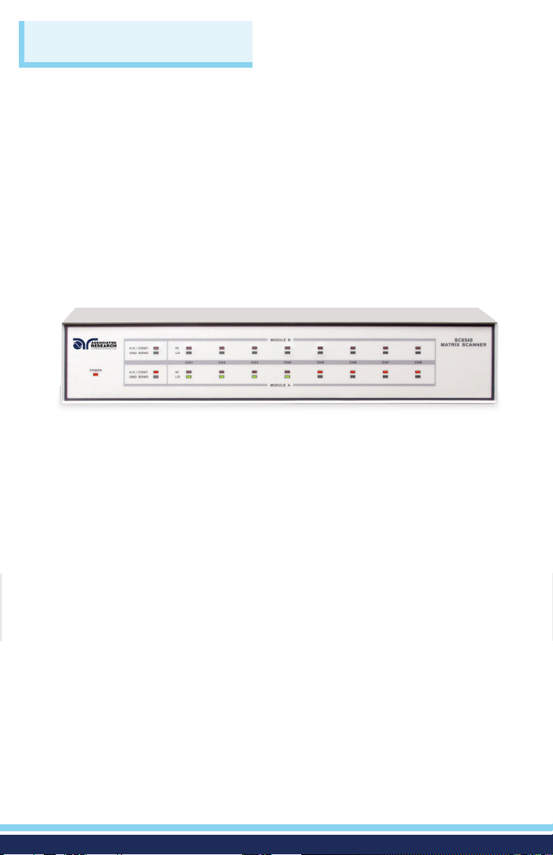
LED Indicators
The two leftmost LEDs for Module A and Module B indicate the type of module
that has been installed. If the Red LED is illuminated there is a High Voltage
module present. If the Green LED is illuminated there is a Ground Bond module
present. During a test, individual LED indicators for each output indicate
whether the output is set as High, Low, or Open. If the channel is set as a High
Voltage Output, Ground Bond Output, or Continuity Current Output the red
LED will light up. If the channel is set as Return, the green LED will light up. If
the High Voltage channel is set to Open, no LED will light up.
13
Page 14
CONNECTIONS
OPERATING THE SC6540 WITH LINECHEK 620L
SETUP
This option allows the 620L to be connected to an Associated Research SC6540
Modular Scanning Matrix, model HN. With this option installed and a Scanner
connected to the Scanner control bus on the rear of the instrument, the 620L
and accompanying Scanner can be used for multi-point Line Leakage testing.
The 620L will provide power and all necessary signals to the corresponding
Scanner inputs.
SC6540 Slave
SCANNER BUS INPUT
CAUTION
CH1
SCANNER BUS OUTPUT ADDRESS
A B
1 2 3 4 5 6 7 8
ON
CURRENT
HIGH VOLTAGE
CAUTION
HIGH VOLTAGE
5.0 KY MAX.
5.0 KY MAX.
H.V.
RETURN
CH2 CH3 CH4 CH5 CH6 CH7 CH8
EXTERNAL MD INTERNAL MD MODULE
277VAC MAX.
30A MAX.
L N L
MD CIRCUITS REMOTE I/O
N
DUT OUTPUTS H.V. / H.A. INPUTS
PROBE HI
PROBE LO
CAUTION
HIGH VOLTAGE
4KV MAX.
CASE
GND
DUT OUTPUT
CAUTION
HIGH VOLTAGE
4KV MAX.
30A MAX.
CURRENT
SCANNER
REMOTE OUTPUT
H.V.
RETURN
CAL.
GND
SIGNAL OUTPUT SIGNAL INPUT
INPUT
115V ~/ 250V ~
2AMAX., 50Hz / 60Hz
T2A 250V
RS232
VOLTAGE
SELECTOR
115
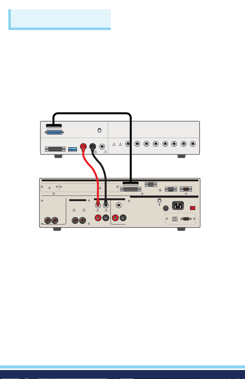
In order to connect the Scanner to the 620L, four connections must be made.
Connect the Scanner control bus from the Scanner output on the rear panel
of the 620L to the input on the rear panel of the Scanner using the included
communications cable (38592). Connect the Probe-HI output on the panel of
the instrument to the Current input on the panel of the Scanner. Connect the
Probe-LO output on the panel of the instrument to the Return input on the
panel of the Scanner. Finally, plug the DUT into the universal adaptor box.
LINECHEK 620L
14
Page 15
CONNECTIONS
OPERATING THE SC6540 WITH LINECHEK 620L (Continued)
OPERATION
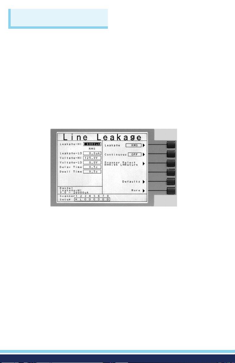
Within the Line Leakage Edit screen on the 620L, the “Scanner Select”
parameter (soft key) will automatically appear when the highlighted cursor
moves to the Scanner Setup area using the Up and Down Arrow keys or Enter
key. Press the “Scanner Select” soft key to toggle the Scanner channel between
H (high), L (low), or O (off). Press the Left and Right Arrow keys to move the
highlighted cursor to the corresponding Scanner channel. Setting a channel
to H will connect the Probe-HI of the 620L to the corresponding Scanner
channel. Setting a channel to L will connect the Probe-LO of the 620L to the
corresponding Scanner channel.
The operator may set the Scanner on a test-by-test basis. For example, for test
step 01, the operator may set each of the Scanner channels in a particular
conguration. For test step 02, the operator may wish to change the conguration
of each Scanner channel.
15
Page 16
Safety Is Our Only Focus
For additional information about these and other key features of the SC6540, please consult the
full Operation and Service Manual or call us toll-free 1-800 -858-TEST (8378) or 1-847-367-4077
© Associated Research • arisafety.com
®
FOLLOW US!
5/2018
 Loading...