


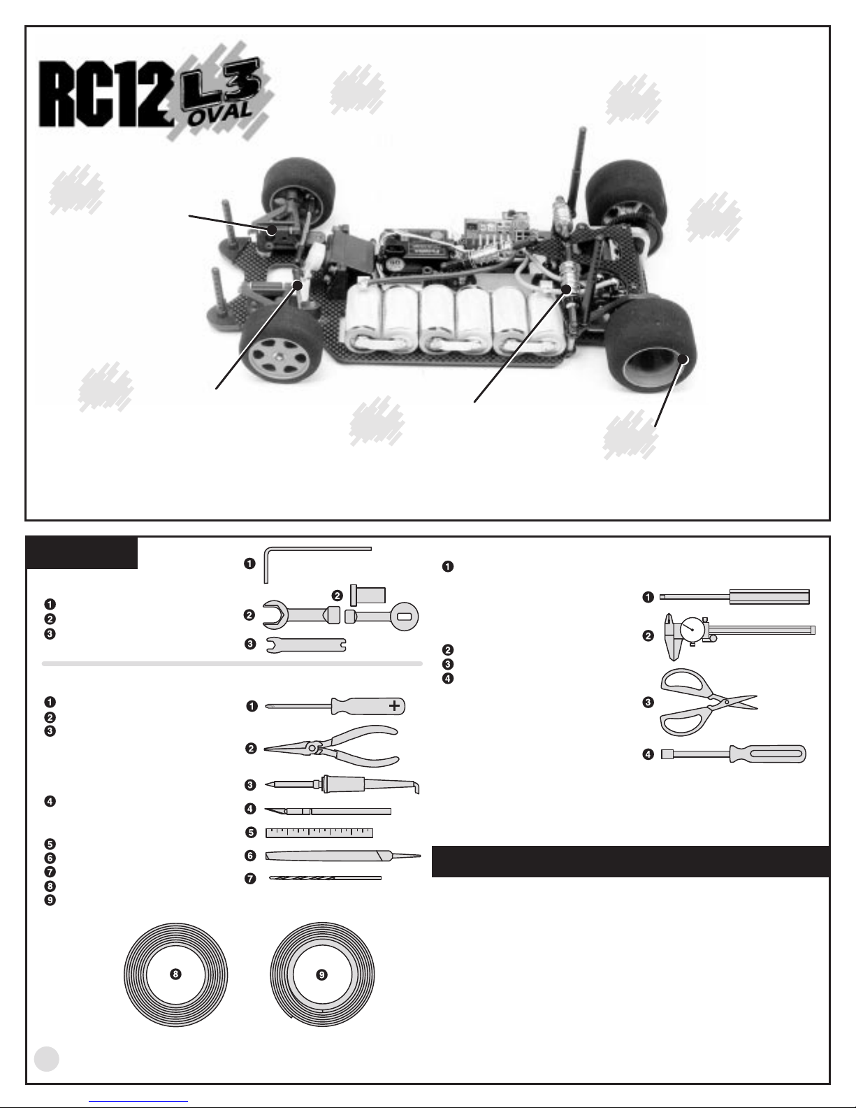
RC12 L3 Oval

INSTRUCTION MANUAL FOR THE
#4016 RC12L3 OVAL KIT
©1999 Associated Electrics, Inc.
1:12 SCALE OVAL KIT
SAVE THIS MANUAL!
Use with current catalog for future,
hassle-free re-ordering of parts.
#4016
Race-proven
Facto ry Tea m
blue alum inum screw s
and ball ends
Carbon-fiber
Com posite Chassis
Dynam ic Strut
front suspension
Facto ry Tea m
blue titanium
tu rn b u c k le s
TOOLS
KIT TOOLS SUPPLIED
Allen wrenches, .050", 1/16", 3/32"
shock tools
metal turnbuckle wrench
EXTRA STUFF NEEDED
Phillips screwdriver #2
needlenose pliers
soldering iron (40-50 watts) and a
small amount of Rosin core solder.
Pencil-type soldering iron is better
than the gun type.
HOT!
hobby knife
cuts plastic and fingers with equal
ease, so be careful.
precision ruler
file
hand drill with 3/32" (or #43) drill bit
electrician's tape
strapping tape
DANGER! Tip is
WARNING!
This knife
VCS M icro Shocks
3 shock design
fo r b e s t d a m p e n in g
HELPFUL TOOLS (NOT REQUIRED)
Allen drivers (straight Allen wrenches with hex shaped handles)
such as the following made by Associated:
#6957 .050" Allen wrench
#6958 1/16" Allen wrench
#6960 3/32" Allen wrench
#6961 2.5mm Allen wrench
Vernier calipers
Hobby scissors
Nut drivers (screwdriverhandled hex socket tools) such
as the following from Associated:
#SP-86 3/16" nut driver
#SP-85 1/4" nut driver
#SP-82 11/32" nut driver
WARNING!
nylon, plastic, or composite materials. The fast rotation speed
can heat up the screws being installed. They can then break or
strip the threads during installation.
ITEM S N EEDED TO CO M PLETE YO U R KIT
R/C two channel surface frequency radio system.
1
Battery pack (6 cell).
2 *
3
Battery charger (we recommend a peak detection charger).
Electronic speed control.
4 *
5 *
R/C electric motor.
Pinion gear, size to be determined by type and wind of motor you will
6 *
be using.
1:12 scale Lexan body.
7
Wide
battery
slots
Pro-Line/Jaco
wheel/tire com bo
fro n t a n d re a r
Do not use a power screwdriver to install screws into
2
*Available from Team Associated. See your catalogs.
REACHING US
CUSTOMER SUPPORT
(714) 850-9342
Fax (714) 850-1744
web site: http://www.teamassociated.com
©1999 Associated Electrics, Inc.
BEFORE BUILDING
OPEN THE BAGS IN ORDER
The assembly is arranged so that you will open and finish that
bag before you go on to the next bag. Sometimes you w ill
have parts remaining at the end of a bag . T h es e will
become part of the next bag.
amount of small parts. To make it easier to find the parts, we
recommend using a partitioned paper plate for spreading out
the parts so th e y w ill b e e a s ier to find .
MANUAL FORMAT
The following explains the format of these instructions.
The beginning of each section indicates:
1
Which bag to open
("BAG A").
2 Which pa rts y o u w ill u s e fo r th os e s te p s . R e move only the
parts shown. "1:1" indicates an actual size drawing; place
your part on top and compare it so it does not get confused
with a similar part.
3
Which tools you should have handy for that section.
4
In some dra w in gs , th e w o rd
which direction is the rear of the car to help keep you oriented.
Some bags may have a large
"REAR"
with an arrow indicates
ASSOCIATED ELECTRICS, INC.
3585 Cadillac Ave.
Costa Mesa, CA 92626
USA
5 The instructions in each step are ordered in the order you
complete the m, so read the words AND fo llo w th e p ictu re s . T he
numbers in circles are also in the drawing to help you locate
them faster.
6 When we re fe r to le ft and right sides o f th e ca r, w e a re
referring to the dr ive r's p o int o f v iew inside the car.
SUPPLEMENTAL SHEETS
We are constantly developing new parts to improve our kits.
These changes, if any, will be noted in supplementary sheets
located in a parts bag or inside the kit box. Check the kit box
before you start and each bag as it is opened. When a
suppleme n t is fo u n d, attach it to the appropriate se c tio n o f th e
manual.
Now clear off your workbench,
line up some paper plates,
grab your 50-cent soda, 39-cent cheeseburger, $12.99 music
CD, and let's begin!
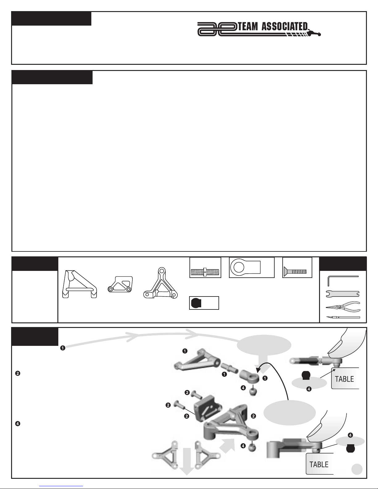
BAG A
REMOVE THESE
PARTS FOR:
TEAM: step 1
8405, qty 2
upper suspension
arm
step 1
ASSEMBLE UPPER
SUSPENSION ARM
LEFT S ID E
Assemble parts #8405, 8415,
and 8411.
ATTACH UPPER ARM MOUNT TO LOWER ARM
Attach #8407 0° mount to the #8419 lower suspension
arm using two #8409 screws.
difficult to screw in. Turn carefully so y ou do n ot s trip
out the head.
INSTALLING UPPER AND LOWER PIVOT BALLS
Before popping in the #8417 pivot balls, make sure
3
there are no burrs inside the pivot ball holes.
Pop the #8417 pivot balls into the suspension arms as
shown. Make sure that the shoulders of the pivot balls
in the lower suspension arms are facing upward and
the pivot balls in the upper arm are facing downward
as shown. Orient ball to the rounded side of the upper
arm as shown.
5
Now assemble the right side.
8407, qty 2
0° upper suspension arm
mount
WARNING!
Screws are
8419, qty 2
lower suspension
arm
8409
(blue)
right side
8415, qty 2
upper suspension
arm turnbuckle
8417, qty 4
pivot ball
8405
8409 (blue)
8407
F
R
O
N
T
1:1
left side
1:1
8411, qty 2
upper suspension
arm eyelet
8415
8417
8417
1:1
Match this number
to the text to find
your way faster
8411
the rounded corner
8419
should face up
1:1
8409, qty 4
4-40 x 1/2"
shoulder screw,
blue aluminum
shoulder down
the side with
TOOLS USED
1/16"
shoulder up
3
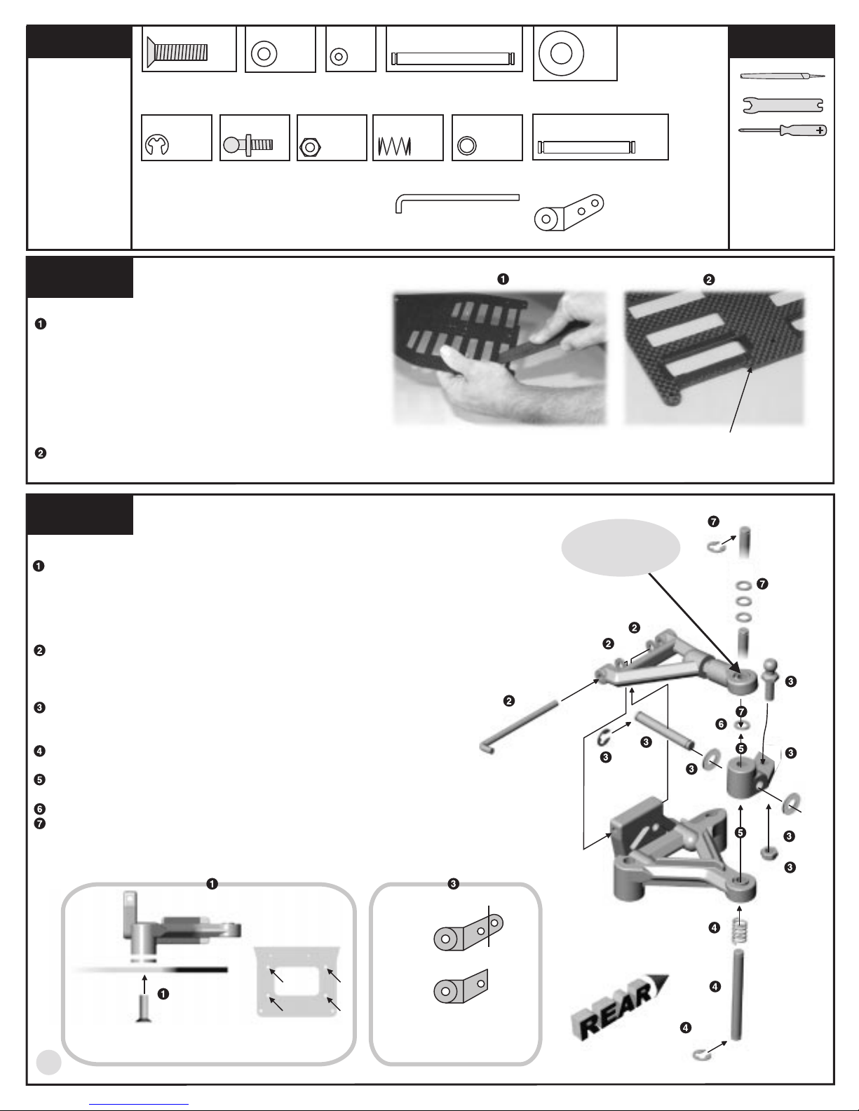
BAG A
REMOVE THESE
PARTS FOR:
TEAM: steps 2-3
8439, qty 4
8-32 x 5/8
blue aluminum
1:1
4187, qty 4
spacer
1:1
1:1
8413, qty 4
caster shim
4403, qty 2
kingpin
1:1
1:1
3323, qty 4
#8 thick washer
TOOLS U SED
1:1
6299, qty 6
E-clip
1:1
4448, qty 2
ball end
blue aluminum
4449, qty 2
4-40 locknut
step 2
FILE THE CHASSIS
Use your file to bevel the slots on the top of the chassis so
the edges won't cut through the battery cell wrap.
WARNING!
health. File in a well ventilated area. Then wash the
chassis with running water and dry with paper towels.
Wash your hands afterward with cold water and soap.
Deposit graphite filings in trash.
TAPE THE CHASSIS
Insulate the battery slots by wrapping the slots with
electrical tape.
step 3
LEFT SID E
SUSPENSION ARMS TO CHASSIS
Place two #3323 washers where shown and bolt the
suspension arm on the #4509 chassis with two #8439 blue
aluminum screws from underneath the chassis as shown
below. Do the other side.
Graphite dust can be harmful to your
1:1
1:1
4114, qty 2
spring, .018
8413, qty 2
hinge pin
1:1
8425, qty 8
kingpin shim
1599, qty 2
axle
NOTE: The bottom of the chassis
has the screw holes countersunk.
1:1
8421, qty 2
offset steering
block
the side with
the rounded corner
should face up
chassis 4509
6299
8425
UPPER ARM TO THE SUSPENSION MOUNT
Assemble the upper arm assembly to the suspension mount
as shown, using the #8413 hinge pin and #8413 shims.
FINAL FRONT SUSPENSION ASSEMBLY
Cut the #8421 steering blocks as shown below. Assemble
the steering block as shown using parts #1599, 6299, 4448,
4187, and 4449.
Place one #6299 E-clip on the bottom of the #4403 kingpin
then slide the #4114 spring over.
Slide the #4403 kingpin completely through the bottom of
the suspension arm and up through the steering block.
Place one #8425 shim on top of the #8421 steering block.
Now push the upper arm over the kingpin. Place three
#8425 shims over the kingpin and secure with a #6299 Eclip.
8
Do the other side.
3323
chassis
8439
chassis (top view)
FRONT VIEW SHOWN
4
8413
8421
before
after
CUT STEERING BLOCK
AS SHOWN
8413
6299
8413
1599
4448
8425
8421
4187
4187
4449
4114
4403
6299
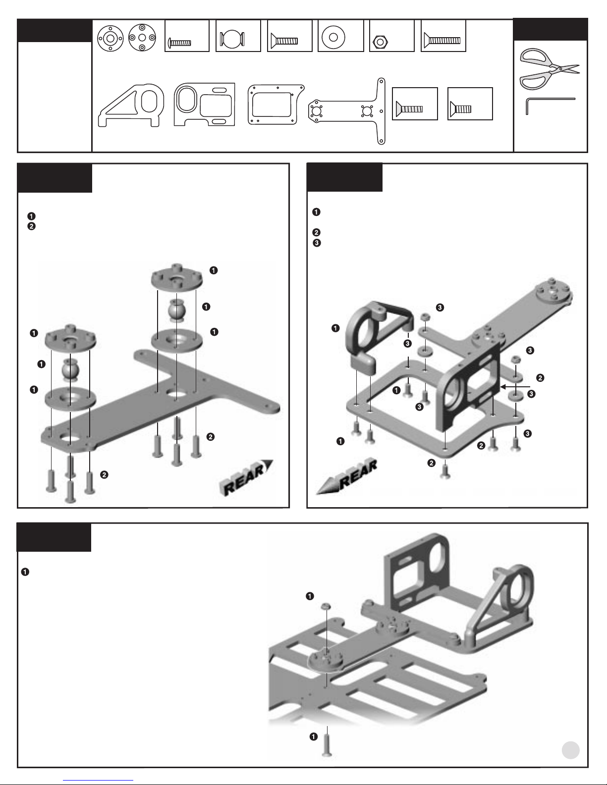
BAG B
REMOVE THESE
PARTS FOR:
TEAM: steps 1-3
4335, qty 2 ea
pivot socket,
upper and lower
1:1
4334, qty 8
2-56 x 5/16
1:1
4336, qty 2
pivot ball
1:1
6292, qty 2
4-40 x 3/8
1:1
4526, qty 2
T-bar spacer
1:1
4449, qty 3
4-40 locknut
1:1
6922, qty 1
4-40 x 1/2
TOOLS USED
4536, qty 1
left rear bulkhead
4537, qty 1
motor bulkhead
step 1
LEFT S ID E
T-BAR ASSEMBLY
Assemble the #4335 T-bar sockets and #4336 pivot balls.
Secure the T-bar pivot assembly to the #4522 T-bar using
eight #4334 screws as shown, installing both on the same
side of the T-bar. The side with the screw head showing will
be the bottom.
4335
4336
4335
4336
4335
4335
4334
4532, qty 1
lower pod plate
4522
4522, qty 1
T-bar, .063"
1:1
6934, qty 3
4-40 x 3/8
blue aluminum
1:1
.050", 1/16"
7673, qty 2
4-40 x 5/16
step 2
RIGHT SIDE
REAR POD ASSEMBLY
Bolt the #4532 lower pod plate to the black #4536 left bulkhead
with three #6934 blue aluminum screws.
Bolt the aluminum #4537 motor bulkhead with two #7673 screws.
Attach the #4532 lower pod plate to the T-bar with two #4526
spacers, two #6292 screws, and two #4449 locknuts. The spacer
goes between the T-bar and the pod plate. The T-bar is on top.
4449
4536
4532
6934
4526
6934
6292
6934
7673
4449
4537
4526
6292
4334
step 3
LEFT S ID E
T-BAR TO CHASSIS
Insert the #6922 sccrew through the chassis hole shown
and into the T-bar and secure with a #4449 locknut.
4449
6922
7673
5
 Loading...