


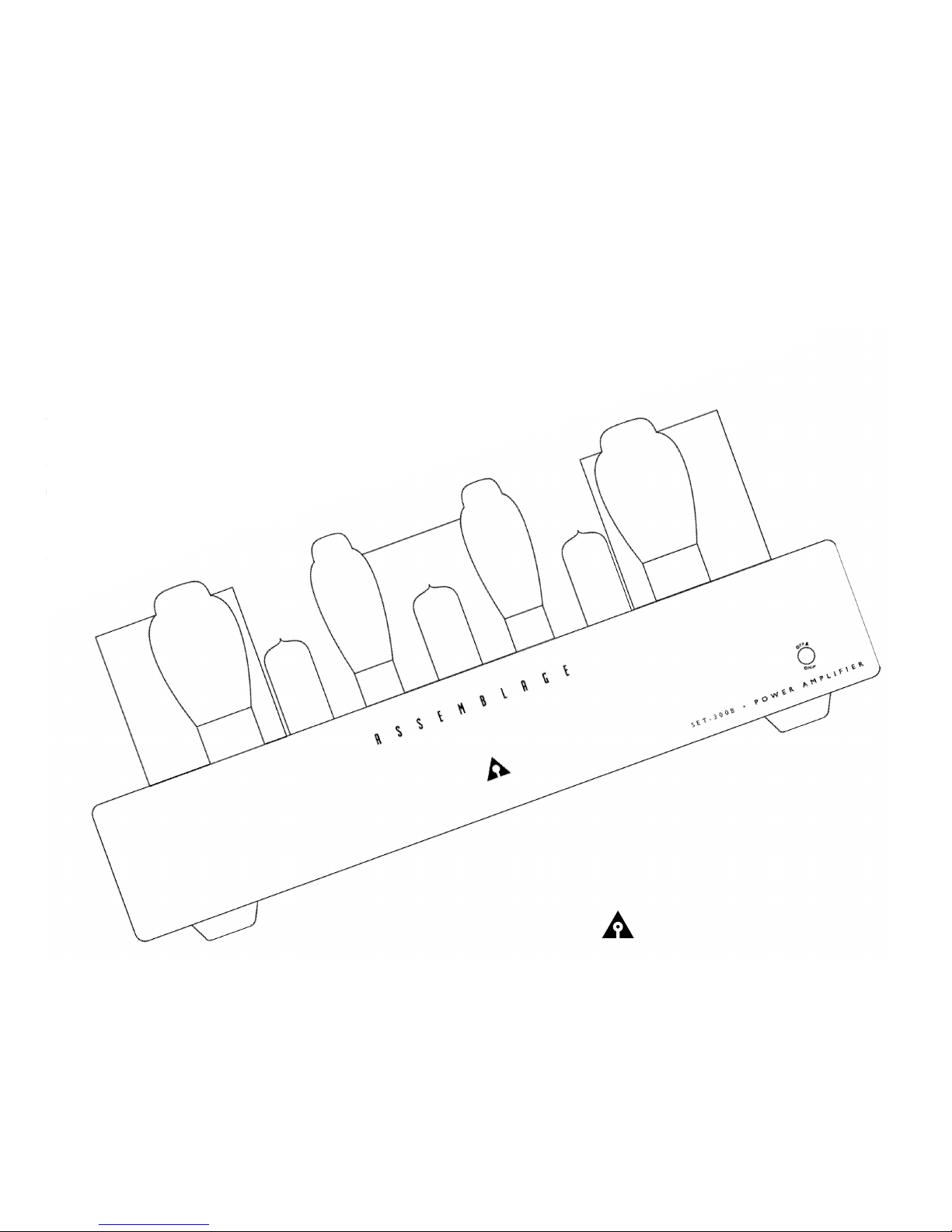
SET-300B
Construction and Operation Manual
A S S E M B L A G E
S E T - 3 0 0 B P O W E R A M P L I F I E R

Dear Assembler,
Congratulations on purchasing the Assemblage SET-300B power amplifier. We are very proud of the Assemblage SET-300B, both
technically and perhaps more import a n t l y, sonically. Utilizing modern, high quality parts, the SET-300B has been designed to pro v i d e
many years of tro u b l e - f ree operation, using readily available tube types (these are tube types, which are still in production - and will
continue to be so).
Assemblage SET-300B Assembly Manual
Page Contents
4 P a rts List
5 Tools re q u i re d
6 S E T-300B Functions
8 B e f o re You Start
9 Stripping/soldering instru c t i o n s
1 0 Assembled PC Board s
1 1 Main PC Board Parts Placement Guide
1 2 Assembly Instru c t i o n s
1 4 S c h e m a t i c s
1 9 Mono Block Operation Setup
2 5 Tro u b l e s h o o t i n g
2 5 Assemblage SET-300B Signature Upgrade and Pre v i e w
2 6 S p e c i f i c a t i o n s
2 7 F u t u re Upgrades
2 7 Guarantees and Wa rr a n t y
• Initial pre p a r a t i o n - p a rts count schematic/numbering conventions
• First stage - board stuff i n g
• Second stage - bottom cover feet, transformer removal, installation of RCA jacks, mute switch, binding posts,
300B sockets, IEC module & input signal cable.
• T h i rd stage - wiring of power transform e r, output transformers, choke, IEC socket, and correct
configuration of power transformer primary windings (e.g. 100/120/200/220/240 V).
• F o u rth stage - installation of PC board s
• Fifth stage - faceplate & power switch shaft mounting.
• Sixth stage - final check
• Seventh stage - last step
Warning and Disclaimer of Liability
When constructing this kit, take care that the assembly steps are followed pre c i s e l y. Be aware that there will be dangerous high
voltages present in the amplifier. Under no circumstances does The Parts Connection or Sonic Frontiers International assume
liability or responsibility for injury or damages sustained in the operation or assembly of this equipment, or for damages to any
equipment connected to it. If you have any questions re g a rding the assembly or set up of the SET-300B, please do not hesitate to
contact us.
2790 Brighton Road, Oakville, Ontario,Canada L6H 5T4
Toll Free: 1-800-769-0747 (U.S. and Canada)
Telephone: (905) 829-5858
Facsimile: (905) 829-5388
Web Site: http://www.sonicfrontiers.com/TPC
E-mail: TPC@sonicfrontiers.com
3

Parts List
Please note, if you are planning to install the Signature Parts Upgrade kit at this same time, take note of the parts labeled “Sig.” in this manual. Refer to the Parts
Upgrade Instructions for these replacement parts.
I t e m / Va l u e Q t y / U n i t R e f e rence Designators
I t e m / Va l u e Q t y / U n i t R e f e rence Designators
Printed Circuit Boards
q Main Board 1 L a rge main PCB
q Power Supply PCB’s 3 Filter Banks Main, Left and Right
q AC Switch PCB 1 Side mounted switch PCB
Semiconductors
q TL400G Bridge - 4A 200PIV 2 BR100; LBR100
q RB151 Bridge - 1A 1000PIV 1 B R 4 0 0
q SF4007 - 1A 1000PIV 4 D1, 2; LD1, 2
q LED - Coool Blue 1 L E D 1
Capacitors
q 0.1uF 50VDC 3 CC1, CC2, CC3
q 0.47uF 400VDC (Sig) 2 C3; LC3
q 470uF 16VDC (Sig) 2 C1; LC1
q 100uF 100VDC (Sig) 2 C4; LC4
q 220uF 160VDC 2 C2; LC2
q 10uF 450VDC 5 C5, C6, C300; LC5, LC6
q 100uF 400VDC 2 C200A, C200B
q 220uF 400VDC 4 C202A, C202B; LC202A, LC202B
q 470uF 400VDC 2 C201A, C201B
q 4700uF 16VDC (Sig) 5 C100, C101, C400; LC100, LC101
q 0.1uF 275VA C 1 A C 1
Resistors 1/2W
q 1K Metal Film (Sig) 2 R2; LR2
q 1K2 Carbon 1 R F 1
q 100R H4 HOLCO (Sig) 4 R5, R8; LR5, LR8
q 100R Metal Film 8 R11, R12, R301, R302, R400,
q 475R Metal Film (Sig) 2 R3; LR3
q 100K H8 HOLCO 2 R1; LR1
q 249K Metal Film (Sig) 2 R10; LR10
Resistors 1-2W
q 220K 2W 8 R205A, R205B, R206A, R206B,
q 33K 2W (Sig) 2 R4; LR4
q 68K 2W 4 R209A, R209B; LR209A, LR209B
q 100K 2W 1 R 3 0 0
q 150K 2W 2 R210, LR210
R401; LR11, LR12
R208A, R208B; LR208A, LR208B
Chassis Components
q Main Chassis 1
q Main Chassis Bottom Cover 1
q F ront Panel - Aluminum 1
q Switch Button 1
Transformers/Choke
q O/P Tr a n s f o rm e r s 2
q Power Tr a n s f o rm e r 1
q 4H 250ma Choke 1
Vacuum Tubes
q 6SN7GT / 6H8C 1 V 2
q 6 B X 7 G T 2 V1, V3
q G Z 3 7 2 V6, V7
Chassis Mounted Hardware
q RCA Jack - RED (Sig) 1 RCA Audio I/P Right
q RCA Jack - WHITE (Sig) 1 RCA Audio I/P Left
q Toggle Switch 1 Mute Switch
q DPST AC power switch 1 AC power switch
q 4 Pin Ceramic Socket 2 300B sockets
q Dual Binding Posts (1pr) (Sig) 2 Speaker Posts
q IEC Socket 1 AC Input
q Black Rubber Chassis Feet (Sig) 4 Chassis bottom cover
q Solder lug #6 3/4” 2 Solder Lug
q Fuse 2.5A or 1.25A Slo-Blo 1 F 1
Mounting Hardware
q M3 10mm (3/8”) Blk CS scre w 2 IEC socket
q #6-32 x 1/4” Zinc Philips 2 Solder lug attachment,
q #6-32 x 1/4” Blk Philips 1 2 Holds bottom cover
q #6-32 x 3/4” SS Philips 4 F e e t
q #8-32 3/8” Blk Philips 2 Holds Choke
q #10-32 3/8” Blk Philips 1 2 Tr a n s f o rm e r s
q #10 Blk Split Wa s h e r 1 2 Tr a n s f o rmers
q Nylon Wa s h e r s 4 300B tube sockets
q #6-32 kepnut 4 Holds 300B Sockets
q #8-32 kepnut 2 Holds Choke
q #10-32 kepnut 2 Holds Faceplate
I/P Com. to Chassis
Resistors 5W
q 5R6 3W 4 R200, R201, R202, R203
q 10k 3W (Sig) 2 R6; LR6
q 0.56R 5W 4 R100, R101; LR100, LR101
q 1K 5W 2 R207; LR207
q 3K 5W 4 R13B, R13C; LR13B, LR13C
q 3K9 5W 4 R13, R13A,; LR13, LR13A
q 10K 5W 2 R7; LR7
q 15K 5W 4 R9A, R9B; LR9A, LR9B
q 6R8 5W 1 (+HV See text)
Trimpot
q 200R 1/2W 2 VR1, LV R 1
PC Board Hardware
q 8 Pin PCB Mount Octal 5 V1, V2, V3, V6, V7
q #4-40 1/2” Stand-off 1 0 Under V1, V2, V3, V6, V7
q #4-40 1/4” SS Philips PH 2 0 V1, V2, V3, V6, V7 Stand-off’s
q #4 Lock Wa s h e r 1 0 V1, V2, V3, V6, V7 Stand-off’s
q #6-32 1/4” SS Philips PH 2 2 Holds PCB’s to Chassis Stand-off’s
q #6 Lock Wa s h e r 4 AC SW PCB & Under Gro u n d
4
S c rews
Hookup Wires & Associated
q Shielded 4 conductor (Sig) 24” Shielded input cable
q Hook-up Black 18awg 48” IEC socket, Spkr posts, Filter Banks
q Hook-up Green 18awg 24” G round wiring
q Hook-up Red 18awg (Sig) 12” power supplies B+, B+1
q Hook-up Brown 18awg 12” power supplies B+2, LB+2
q Hook-up Blue 18awg 1 2 ” power supply B+3, LB+3
q Heat-shrink tubing Black 1 / 8 ” 6” IEC Te rminals & LED
q Heat-shrink Tubing Black 3 / 1 6 ” 6” I/P and AC primary wiring
q #30 Twist Connectors 4 O/P Transformer Secondary
q Kimber Kable TCSS (Sig) 4” To 300B Grids
Miscellaneous
q 3” Cable Ti e s 8 Tr a n s f o rmer wire s
q Cable Tie Mounts 1 Power transformer wire s
q Extension Shaft 2 AC Switch to Front panel button
q Shaft Coupler 2 AC Switch to Front panel button
q Nylon Blk Hole Plug 1 Hole plug for Level Control
q Wo n d e r s o l d e r 1 0 f t
q S o l d e rw i c k 1 f t
q 18/3 CSA Power Cord 6 Foot 1
q C o n s t ruction and Operation Manual (If you cannot locate this, we are in big tro u b l e ! )
q Wa rranty Card
Configurations
k n o c k o u t
3
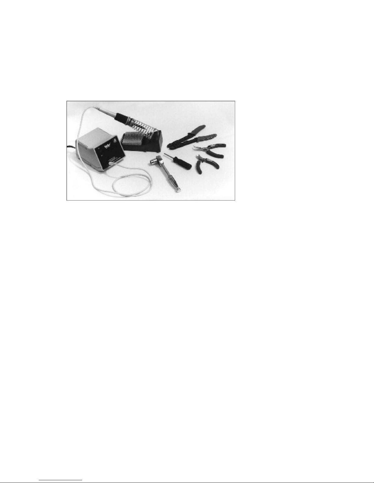
Tools Required
In addition to the parts supplied in the kit, you will need the following tools to complete construction of
the SET-300B kit.
1 Pencil tip soldering iron of good quality (700°F tip temperature)
1 #0 Philips screwdriver
1 12mm wrench or ratchet (1/2” will also work)
1 10mm combination wrench (not shown) (3/8” will also work)
1 5/16” nut driver
1 Pair of needle nosed electronics pliers
1 Wire stripper or hobby knife (If you trust yourself with your fingers!)
1 Ruler/Scale (not shown)
1 Voltmeter (optional)
5
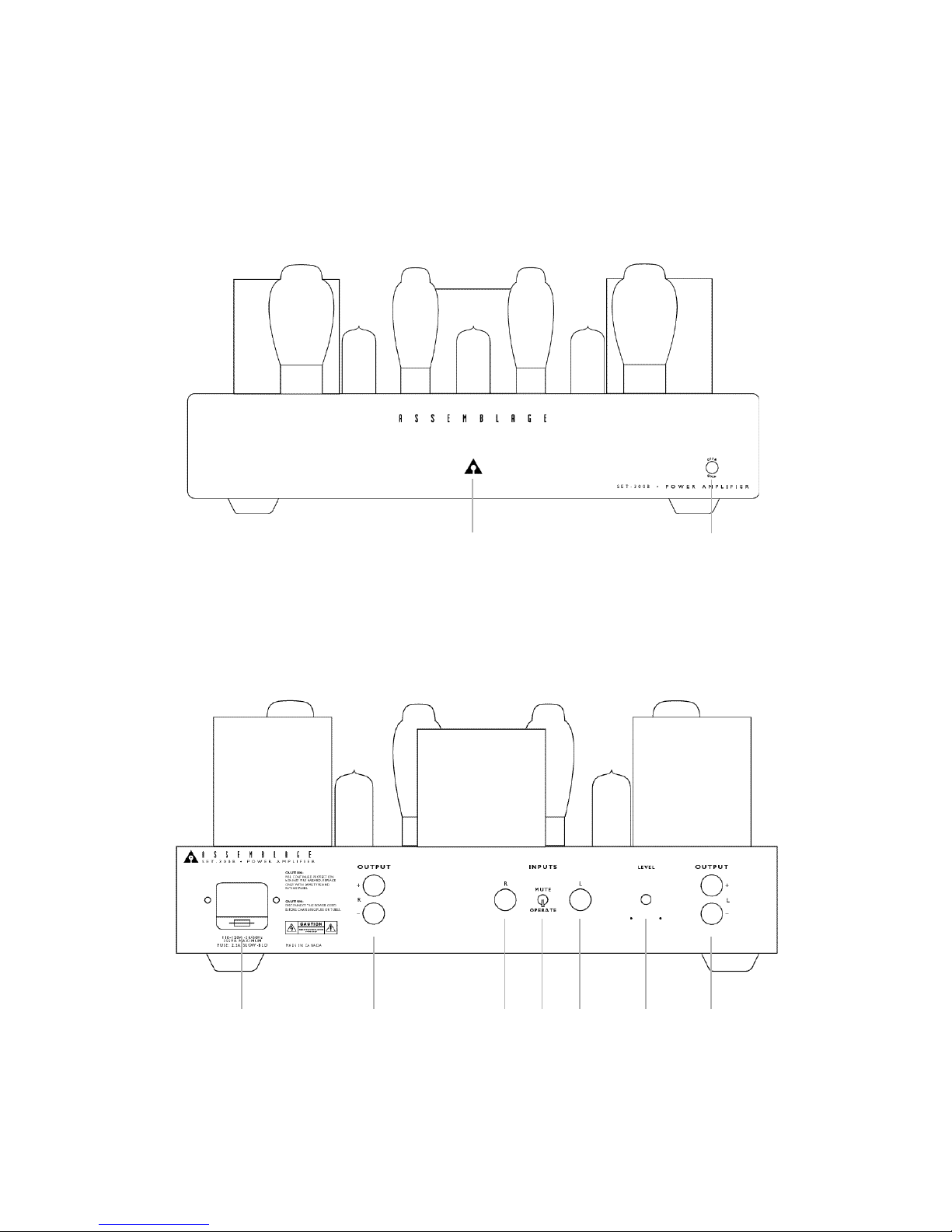
SET-300B Functions
A
B
C D E D
GEF
56

Control Functions
A LED
When the coool blue LEDis lit, the SET-300B is “ON”,
receiving power from the power supply.
B ON-OFF button
When in the ON position (button depressed), high
voltage power is received by the SET-300B circuitry
f rom the power source. Due to the warm up
characteristics of tubes, it will take 30 seconds for the
tubes to pass full signal. It is suggested that the
SET-300B remain muted or the volume control on the
preamp be turned down for this first minute. When in
the OFF position (not depressed), the SET-300B is not
receiving power and is not operational.
Connection Functions
C Detachable AC Power Cord Socket
Plug the Detachable Power Cord into this socket.
D Speaker Connection Posts
These 5-way binding posts accept a connection from
one pair of speakers. The negative connections are to
be made to the black connectors; left speaker to the
terminals marked left and right to the terminal marked
right.
E Preamplifier Input
This input accepts RCA input connections from an
external preamp or crossover; connect left channel to
left channel and right channel to right channel.
F Mute/Operate Switch
The input of the 300B may be muted via this switch.
This is handy when changing interconnect cables or
even isolating system components for tro u b l e
shooting purposes.
G Optional Set - Control
This level control may a switched attenuator or
potentiometer from TPC or one of your own favorites.
This will allow a source device to be dire c t l y
connected to the amplifier input jacks there b y
bypassing an outboard preamp.
WARNING - DISCONNECT T H E AC D E TAC H A B L E
P OW E RC O R DF RO MT H ES E T- 3 0 0 B AND WAIT 5
MINUTES BEFORE REMOVING BOT TOM COV E R ,
TUBES OR FUSE.
7

Before You Start - Kit Overview
B e f o re you start assembling your SET-300B, please take a few
minutes to read this preface on the construction manual and the kit.
Zen and the Art of Electronics Assembly:
Assembling a high quality electronic device re q u i res a certain frame
of mind. The object is not to rush through and get the kit assembled
as quickly as possible, but to methodically and correctly put together
the pieces of this audio jigsaw puzzle. The kit could take as long as 68 hours to complete, so plan your attack accordingly and take bre a k s
often, you will find the natural places to do so as you go through the
assembly steps. The final kit appearance will benefit from your re s t e d
m i n d .
If the instructions are followed to the letter, the amplifier will work
c o rrectly right from the start. If you try to assemble the kit purely fro m
the pictures/illustrations without reading the body of the text, your unit
will most likely not work.
Please note that this kit is not intended for the complete novice. A
c e rtain level of competency is assumed in electronics assembly - i.e.
the ability to solder, and to be able to use a voltmeter/multimeter.
General Instructions:
W h e re necessary a simple overview of the upcoming step is
p resented to you before you actually do that pro c e d u re. This little
p reamble will help to clarify the next assembly step and give you a
b roader understanding of the construction methods to use, and
hopefully aid you in getting it right the first time. Following this is a list
of the parts or components that will be needed or constructed in this
immediate section, then a detailed description of the assembly
p ro c e d u res for that section.
The top of the printed circuit boards is the one side that has the white
s i l k - s c reening on it. There f o re you know that the backside has no
s c reening on it and no parts, except it is the backside that the tube
sockets will be mounted to.
Parts Count:
While every precaution has been taken to ensure that you have
received a complete kit, your kit has been picked and packed by
humans. There f o re, please use the Parts List on page 4, to ensure
that you have all parts present and accounted for. Before you
convince yourself that something is missing, check again! Larg e
c a rd b o a rd boxes are notorious for hiding small parts, as are the
packing materials.
Stuffing the PC Boards:
If you inspect the main board (this is the largest of the boards with
which your are supplied with), you will notice that all parts locations
have been labeled with the appropriate part re f e rence designator.
Each diff e rent set of components has been placed in its own
individual bag, which has its own label which lists the part type. (Yo u
will find the re f e rence designators listed on the Parts List.) There f o re ,
when you are asked to install the resistor R1, you simply pro c u re the
labeled bag with that part in it. Once the part is installed and soldere d
in place, you can check that component off the supplied checklist in
this manual. There are also several photos and diagrams detailing
p a rts placement to reduce any possible confusion that may arise
re g a rding parts placement. Please note too, that there may be some
subtle diff e rences between some of the parts shown in the
photographs and those supplied with your kit. On occasion, our
technical staff may substitute parts with ones of equal or higher
q u a l i t y .
N O T E : Talking about part substitutions, there are Signature part s
upgrade kits available for the SET-300B. These upgrade kits re p l a c e
components in the signal path, input wiring, power supply filter caps,
coupling caps, the addition of film bypass caps, and
vibration/isolation components. (see page 25 for details)
The parts for your Assemblage kit have been packaged into several
g roups: capacitors, resistors, semi-conductors, and hard w a re. Each
component type is individually packaged to allow for ease of
identification.
The process of stuffing the main board with parts is in fact a re l a t i v e l y
simple pro c e d u re - Generally the sequence will be to simply obtain
the bag containing the appropriate part, carefully bend the leads,
place the part into the holes in the PC board, then solder and trim the
leads. (Please review our soldering instructions on the next page).
Soldering:
Let it be said once, to get it out of the way - all soldering must be done
with rosin core solder! There is no warranty on equipment in which
acid core solder has been used. Please use the silver solder
p rovided in the kit.
Wire Stripping:
Unless otherwise instructed elsewhere in this manual, the norm a l
p ro c e d u re to ‘pre p a re’ a cut wire is as follows;
q Trim or cut the wire to the desired length.
q Strip back the wire jacket 3/16”(~5mm), to expose the wire inside.
Use your favorite tool, the knife or wire strippers. If you are using the
knife, please be careful and read the instructions on the following
p a g e .
q Twist the wire strands to gather them together and then solder them.
This is called the ‘tinning pro c e s s ’ .
Mechanical Assembly:
The SET-300B has been designed with ease of assembly in mind. To
this extent, the chassis has been designed with built-in standoffs, to
which the PC boards are attached. This allows the PC boards to be
easily installed and re m o v e d .
T h e re is a minimum of wiring involved in putting this kit together generally the power transformer must be wired to the PC boards, the
output transformers connect to the speaker binding posts and the
300B sockets dire c t l y, and the IEC socket connects the power
t r a n s f o rmer and AC switch board. The Mute switch and the input (I/P),
RCA jacks are wired to the Main PC board .
We will leave most wiring until the last few steps, as we will first
c o n c e rn ourselves with correctly placing and soldering all the
components to the PC board s .
Please be sure to follow the installation instructions closely, because
some important mounting details etc. may be included in any step.
78
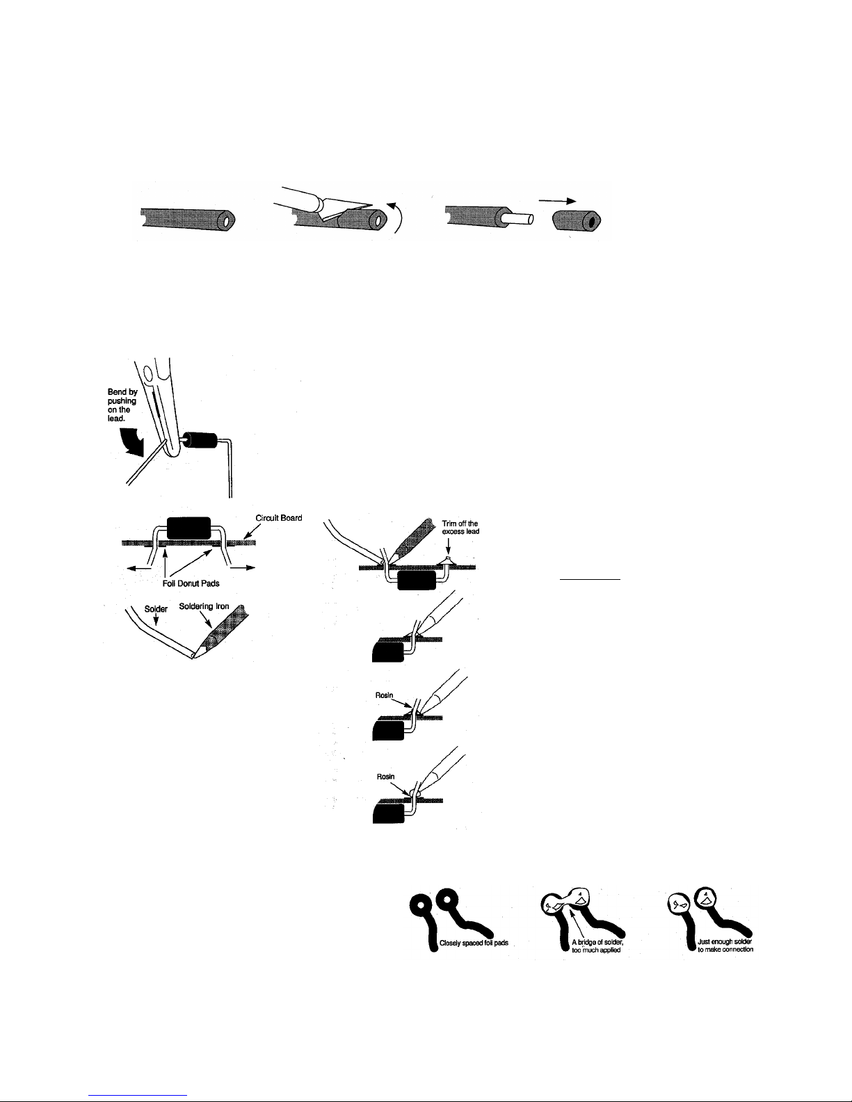
Wire Stripping with a Knife
If you own a wire stripper, we’re assuming you know how to use
it. If not, and you are new to the world of audio construction, you
can use a hobby knife to do the same job. Simply cut around the
insulation leaving an appropriate length for the lead, be very
Soldering
• If a lead bender is not being used, hold the component (resistor,
capacitor, LED,...) with a pair of needle nose pliers and bend the
leads to the appropriate width so it can fit through the donut
pads in its position on the circuit board.
• DO NOT bend the leads by applying pressure to the component,
bend by pushing directly on the lead. Bend only as in the picture,
this will make it easier to remove the parts from the PCB in the
event that you may want to upgrade the part later, without
removing the PCB from the chassis.
• Position the component on the circuit board and hold it in
position as you bend the leads out.
• To help conduct the heat from the soldering iron, “tin” the tip of
iron by applying a touch of solder to the already heated iron tip.
careful to cut only the insulator and not the wire itself. Pull the
excess insulation away and you have your lead. If the wire is
made of strands, twist the lead between your fingertips to keep
it from fraying.
• Push the soldering iron tip against the lead and the foil
donut pad on the circuit board and hold for 2 seconds.
• Then apply the solder to the other side of lead, also
touching the donut pad. Let the heated lead and pad melt
the solder,
the lead.
• Remove the iron and solder and let the connection cool.
Trim off the excess lead.
• NOTE: When done C O R R E C T LY, by heating the lead and
foil donut pad simultaneously, the solder should flow
o u t w a rd, gradually blending from the lead to the foil.
• When done I NC O R R E C T LY, by just heating the foil pad
and not the lead, a hard rosin bead will surround the lead,
insulating it from the connection.
• An I NC O R R E C T solder joint is also done by just heating
the lead and not the foil pad. Here a hard rosin bead form s
on the pad, insulating it from the lead.
• To correct these unacceptable solder joints reheat and if
n e c e s s a ry apply a little more solder.
not the iron tip. The solder should flow aro u n d
Solder Bridges - solder bridges usually happen when too much
solder is used, or the solder is dragged from one connection to
another when heat is applied. If a bridge develops, turn the
circuit board upside down and reheat the connection, allowing
the solder to flow onto the iron tip. Then resolder the connections
as before, being careful that just enough solder is used to make a
c o n n e c t i o n .
• H I N T: It is handy to keep a damp sponge nearby to clean
the iro n ’s tip after each joint is completed.
9
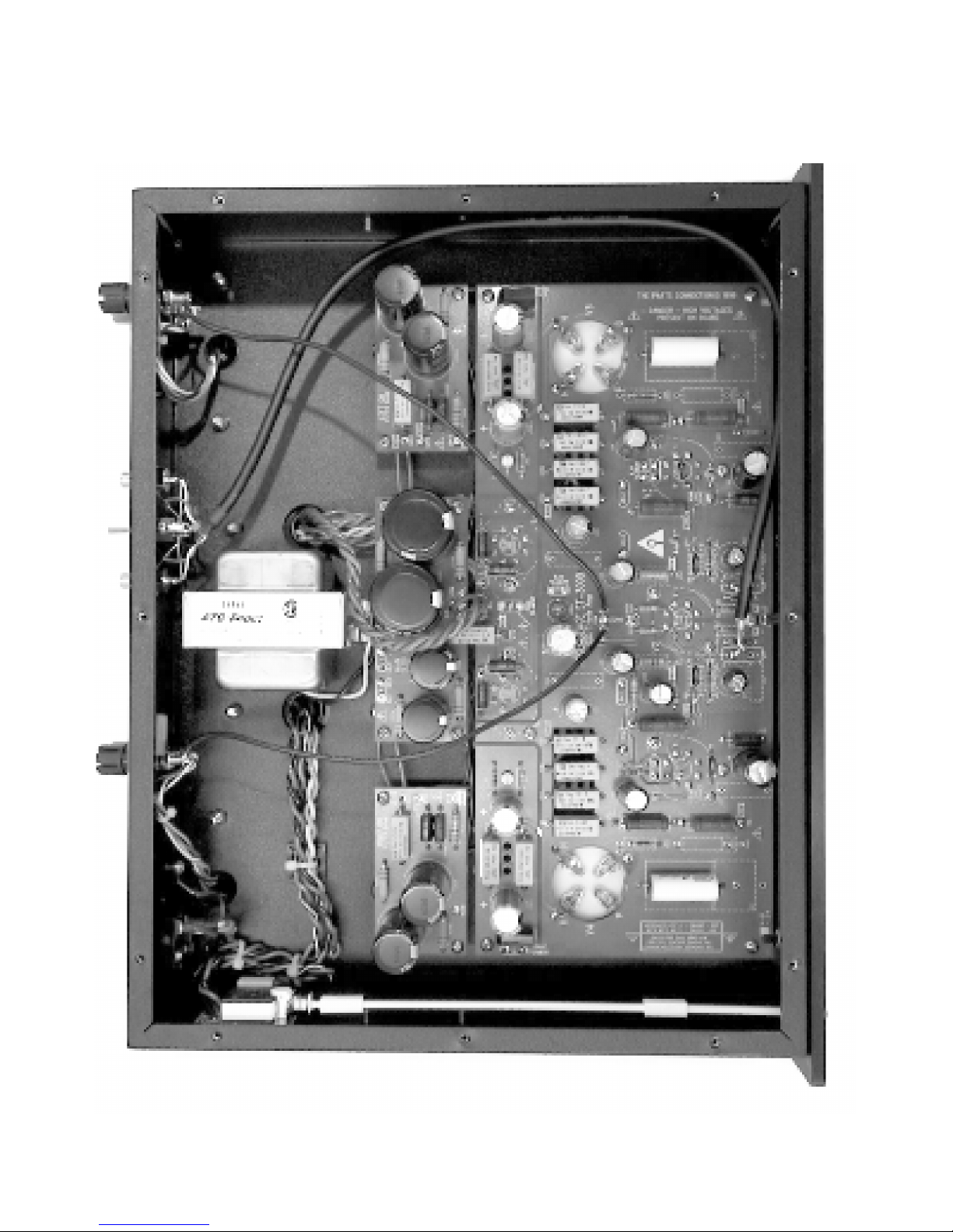
Assembled PC Boards
 Loading...