


IC Radio Standards Specification: RSS-210
ACS Report Number: 11-0071.W06.11.A
Certification Exhibit
FCC ID: U4A-SCYICLS2
IC: 6982A-SCYICLS2
FCC Rule Part: 15.225
Manufacturer: Assa Abloy, Inc.
Model: P1-IM/IKM
5015 B.U. Bowman Drive Buford, GA 30518 USA Voice: 770-831-8048 Fax: 770-831-8598
Manual

P1
PRELIMINARY
PASSPORT 1000
Mortise Lock
Installation Instructions
A8032D
12/10
Copyright 2010, Sargent Manufacturing Company, an ASSA ABLOY Group company.
All rights reserved. Reproduction in whole or in part without the express written
permission of Sargent Manufacturing Company is prohibited.

Table of Contents
PRELIMINARY
Warning ...................................................................................2
1
2
General Description
3
Hardware Specifications
4
Electronic Specifications
5
Installation Wiring Overview
6
Installation Wiring
7
Parts Breakdown
8
Installation Instructions
9
Operational Check
1
Warning
Changes or modifications to this unit not expressly approved by the party responsible
for compliance could void the user’s authority to operate the equipment.
.................................................................3
...................................................................4
.....................................................................7
................................................................17
.........................................................3
.........................................................3
...................................................3
..........................................................7
FCC
This equipment has been tested and found to comply with the limits for a Class A digital device, pursuant to part 15 of the FCC rules. These limits are designed to provide reasonable protection against
harmful interference when the equipment is operated in a commercial environment. This equipment
generates, uses, and can radiate radio frequency energy and, if not installed and used in accordance
with the instruction manual, may cause harmful interference to radio communications. Operation of
this equipment in a residential area is likely to cause harmful interference in which case the user will be
required to correct the interference at his own expense.
Industry Canada:
The term “IC:” before the radio certification number only signifies that Industry Canada technical
specifications were met.
This Class A digital apparatus meets all requirements of the Canadian Interference Causing Equipment
Regulations. Operation is subject to the following two conditions: (1) this device may not cause harmful interference, and (2) this device must accept any interference received, including interference that
may cause undesired operation.
Cet appareillage numérique de la classe A répond à toutes les exigences de l’interférence canadienne
causant des règlements d’équipement. L’opération est sujette aux deux conditions suivantes: (1) ce
dispositif peut ne pas causer l’interférence nocive, et (2) ce dispositif doit accepter n’importe quelle
interférence reçue, y compris l’interférence qui peut causer l’opération peu désirée.
Copyright © 2010, Sargent Manufacturing Company, an ASSA ABLOY Group company. All rights reserved.
Reproductions in whole or in part without express written permission of Sargent Manufacturing Company is prohibited.
10/10/10
1-800-810-WIRE • www.sargentlock.com • A8078A
Observe precautions for handling electrostatic sensitive devices.
!
Warning SARGENT Mfg. Co. v.P Series locksets utilizing a door position switch (DPS) are not rated for,
or intended for use in life safety applications.

Passport 1000 Series P1 PoE Mortise Lock
PRELIMINARY
2
3
4
General Description
The SARGENT Passport Series v.P1 cylindrical lock is available with either an HID® Prox 125 kHz or 13.56 MHz
iCLASS® technology reader. It utilizes existing infrastructure and IEEE 802.3af PoE (Power over Ethernet) providing
access control with Magnetic swipe and optional Proximity Reader and/or Keypad, as well as detailed audit capabilitiestechnology as a proven alternative to traditional access control installations. The v.P1 is a self-contained microprocessor-controlled access control product with non-volatile memory. It uses the existing network cable to communicate with
access control systems. The v.P1 lock holds a total of 2400 different user codes.
Using PoE technology coupled with third party software, this v.P1 online lock offers a complete, integrated
access control system.
The Passport Series v.P1 cylindrical lock may be used for both indoor and outdoor applications. A weatherprotective gasket is recommended for outdoor applications.
HID and iCLASS are registered trademarks of HID Global Corporation.
Hardware Specifications
• Complete locksets with on-board memory
• Magnetic swipe standard with optional 125 kHz
Proximity Reader (specify PRX-), 13.56 MHz
reader (specify IKM-), and/or keypad (specify KP-)
• ADA Compliant
• Easily retrofits existing Passport 1000 door preps
(cylindrical locks)
• Latch 1/2” standard
3/4” throw fire-rated double doors
(optional) (41- prefix)
• Guarded latch
• Outside lever is unlocked through access
control credentials only
Electronic Specifications
• 2,400 users per lock; 10,000 event audit trail
• Multiple time zone and holiday access scheduling
• Centralized lock management
• Real time door status monitoring
• First-In unlock configuration, either by time or by
user (selectable)
• Lock down capable
• Inside lever retracts latch
• Locks furnished for 1-3/4” doors only
• Grade 1; UL Listed
• Outside lever controlled by any combination of
keypad, magnetic keypad, iCLASS, prox (proximity) reader, or mechanical cylinder
• Input Power: PoE Class 2 Device, as defined
by IEEE 802.3af, requires up to 7 watts
over structured cabling
• Uses existing Magstripe keycards (track 2)
• Magnetic Stripe Card Coercivity: HiCo (4000 Oersted) or
LoCo (300 Oersted)
• Supports HID 125 kHz prox or 13.56 MHz iCLASS
credentials (26 - 39 bit); supports CSN reads for other
common 13.56 MHz cards, including MiFare, DesFire, and
Felica
5
Installation Wiring
Overview
SARGENT Passport Series PoE
v.P1 Typical Application
* Lockdown and real-time door
status monitoring available
only when lock is hard-powered
LMT: Lock Management Tool
A. PoE frame harness assembly
B. PoE data hinge from McKinney
(patent pending)
C. PoE door harness* from McKinney
D. DPS: Door Position Switch
(Cylindrical and Exits only)
E. Passport Series v.P1 PoE Lock
* Door width determines length
1-800-810-WIRE • www.sargentlock.com • A8032D 3
Supplied by Others
Network Cable
Network Switch (802.3af)
Surface Mount RJ45
A
B
C
D
E
Copyright © 2010, Sargent Manufacturing Company, an ASSA ABLOY Group company. All rights reserved.
Reproductions in whole or in part without express written permission of Sargent Manufacturing Company is prohibited.
12/15/10

Passport 1000 Series P1 PoE Mortise Lock
PRELIMINARY
6
Ceiling
Ground in
15' Frame
Installation Wiring
A. PoE Frame harness assembly
(From McKinney)
B. PoE data hinge (Patent Pending)
(From McKinney)
Supplied by CI
B-Splice
Crimp Connector
RJ45-M
24AWG
Stranded
Drain
Wire for
Earth
Harness
Certified Integrator (CI) supplies and terminates
Drain Wire
RJ45-F Jack
C. PoE Door harness*
D. Passport 1000 Online P1 PoE Lock
* Order of installation may vary.
Refer to appropriate sections for instructions.
the B-Splice connector and the
Male RJ45 connector from harness to
end user provided facility cable
Patch Cable
Patch Panel to
PoE Switch
Cable: CAT 5e or higher
24 AWG shielded with drain wire
Drain Wire Terminated on Rack
Supplied by End User
PoE Switch
PoE Switch is
Terminated to
Earth Ground
Patch Panel
Approved Software
Copyright © 2010, Sargent Manufacturing Company, an ASSA ABLOY Group company. All rights reserved.
Reproductions in whole or in part without express written permission of Sargent Manufacturing Company is prohibited.
Frame-Side
Harness
Assembly
(15' length)
Cable
drain wire
concealed in
shrink tubing
Cable: CAT 5e or higher
Molex-M
A
24 AWG shielded, 100ohm
Molex-F
Molex-F
B
Molex-M
Wiring to TIA-568-B Standard
Cable: CAT 5e,
26 AWG stranded,
shielded, 100ohm
C
Ground
Ring Terminal
Secured to Lock
Mounting Plate
JST
4-Pin
4-Pin
Molex
D
PoE
Lock
Notes:
• Connectors go on only
one way. They cannot
be placed in an incorrect
position.
• Do not force and do not
offset connectors.
• Be sure they are completely seated (flush).
12/15/10
4 1-800-810-WIRE • www.sargentlock.com • A8032D

Passport 1000 Series P1 PoE Mortise Lock
PRELIMINARY
Installation Wiring (Continued)
A
Frame Harness Installation
Supplied by CI
Crimp Connector
Ceiling
24AWG
Stranded
Drain
Wire for
Earth
Ground in
15' Frame
Harness
Frame-Side
Harness
Assembly
(15' length)
Cable
drain wire
concealed in
shrink tubing
B-Splice
RJ45-M
Cable: CAT 5e or higher
Molex-M
Components and wire harness supplied by McKinney: Suggested installation.
Cut end / ceiling-side PoE harness:
TIA/EIB-568-B Standard Wiring
5
4
6
3
2
1
7
8
Pair Number Wire PIN
1 White/Blue
2 White/Orange
3 White/Green
4 White/Brown
White/Blue 5
Blue 4
White/Orange 1
Orange 2
White/Green 3
Green 6
White/Brown 7
Brown 8
Do not confuse pair numbers with pin numbers. A pair number is
used for reference only (eg: 10BaseT Ethernet uses pairs 2 & 3). The
pin numbers indicate actual physical locations on the plug and jack.
Hinge side of PoE harness:
24 AWG shielded, 100ohm
1. Feed cut end of harness into hole on hinge-side through single access hole.
2. Push one connector back through the hole and feed into the other access hole.
Each of the hinge-side harness connectors should end up threaded through
a different access hole and matched to the same size pin connector from
the door harness:
• 4-pin male molex connector.
• 6-pin male molex connector with ground wire.
B
PoE Data Hinge
4-pin M
4-pin F
Hinge-side harness connectors:
• 4-pin male molex connector
• 6-pin male molex connector with ground wire
Lock-side harness connectors:
• Ring terminal
• (2) 4-pin connectors
6-pin M
Frame PoE Hinge (Patent Pending)
6-pin F
1-800-810-WIRE • www.sargentlock.com • A8032D 5
Copyright © 2010, Sargent Manufacturing Company, an ASSA ABLOY Group company. All rights reserved.
Reproductions in whole or in part without express written permission of Sargent Manufacturing Company is prohibited.
12/15/10

Passport 1000 Series P1 PoE Mortise Lock
PRELIMINARY
PoE Data Hinge
C
Order of installation may vary. Refer to appropriate sections for instructions.
Hinge-side harness connectors:
• 4-pin male Molex connector
• 6-pin male Molex connector with ground wire
Lock-side harness connectors:
• Ring terminal
• (2) 4-pin connectors:
• 4-pin Molex connector
• 4-pin connector
Notes:
• Connectors go on only one way. They cannot be plugged to incorrect position.
• Do not force and do not offset connectors.
• Be sure they are completely seated (flush).
4-pin M 4-pin F4-pin F
PoE Lock
JST
4-Pin
Drain Wire
6-pin F 6-pin F 6-pin M
D
PoE Door Harness
Order of installation may vary. Refer to appropriate sections for instructions.
1. Prop door open.
2. Tape the two lock-side 4-pin connectors to the ring terminal.
3. Using the ring terminal, carefully fish the assembly through the
door channel to the lock.
4. Remove tape from ring terminal and door harness connectors.
Hinge-side harness connectors:
• 4-pin male Molex connector
• 6-pin male Molex connector with ground wire
Lock-side harness connectors:
• Ring terminal
• (2) 4-pin connectors:
• 4-pin Molex connector
• 4-pin connector
Notes:
Copyright © 2010, Sargent Manufacturing Company, an ASSA ABLOY Group company. All rights reserved.
Reproductions in whole or in part without express written permission of Sargent Manufacturing Company is prohibited.
12/15/10
6 1-800-810-WIRE • www.sargentlock.com • A8032D
• Connectors go on only one way. They cannot be plugged to
incorrect position.
• Do not force and do not offset connectors.
• Be sure they are completely seated (flush).
Cable: CAT 5e,
26 AWG stranded,
shielded, 100ohm
4-Pin
Molex

Passport 1000 Series P1 PoE Mortise Lock
9
10
12
13
10
P2
Inside
10
11
Outside
PRELIMINARY
8
Parts Breakdown
P1 PoE Lock with Magnetic Card Swipe With or Without Keypad
11
10
10
10
9
9
8
5
7
5
6
5
4
3
2
1
11
12
12
Inside
13
13
10
14
Outside
ITEM No. PART No. DESCRIPTION
1 52-0757 Lens (Cliplite)
2
3 52-0760 Light Pipe (Cliplite)
4 52-3593 Slim Style Keypad Assembly
5 01-9299 #4-40 x 3/16” Phillips Pan Head Screw
6 52-3591 Swipe Reader Assembly
7 52-0745 Online Interface PCB
8 52-3209 Harness Assembly
9 52-0748 Inside Mounting Plate
10
11 01-1146 #8-32 x 3/8” Phillips Flat Head Screw
12 52-4246 Modular Component
13
14 01-4421 #8-32 x 1/2” T-20 Torx Pan Head Screw
52-0738 Outside Passport Escutcheon Only (Magnetic Swipe and Keypad)
52-0739 Outside Passport Escutcheon Only (Magnetic Swipe)
77-0168 #8-32 x 1-7/8” Phillips Flat Head Screw
01-1176 #8 x 3/8” Phillips Flat Head Wood Screw
52-3592 Inside Escutcheon Assembly
1-800-810-WIRE • www.sargentlock.com • A8032D 7
Copyright © 2010, Sargent Manufacturing Company, an ASSA ABLOY Group company. All rights reserved.
Reproductions in whole or in part without express written permission of Sargent Manufacturing Company is prohibited.
12/15/10

Passport 1000 Series P1 PoE Mortise Lock
PRELIMINARY
Parts Breakdown (Continued)
P1 PoE Lock with Magnetic Card Swipe , 125 kHz Prox and Keypad
10
10
11
3
9
8
7
3
6
5
3
4
3
2
1
9
10
10
13
12
11
Inside
Outside
ITEM No. PART No. DESCRIPTION
1 52-1103 Outside Passport Escutcheon only
2 52-3593 Slim Style Keypad Assembly
3 01-9299 #4-40 x 3/16” Phillips Pan Head Screw
4 52-4243 Swipe Reader Assembly
5 52-1106 Prox Reader Gasket
6 52-4206 Antenna Assembly
7 52-0745 Online Interface PCB
8 52-3209 Harness Assembly
9 52-1109 Back Plate
10 52-0748 Inside Mounting Plate
11
12 01-1146 #8-32 x 3/8” Phillips Flat Head Screw
13 52-4246 Module Assembly
14
Copyright © 2010, Sargent Manufacturing Company, an ASSA ABLOY Group company. All rights reserved.
Reproductions in whole or in part without express written permission of Sargent Manufacturing Company is prohibited.
15 01-4421 #8-32 x 1/2” T-20 Torx Pan Head Screw
77-0168 #8-32 x 1-7/8” Phillips Flat Head Screw
01-1176 #8 x 3/8” Phillips Flat Head Wood Screw
52-3592 Inside Escutcheon Assembly
(Magnetic Swipe, Keypad and Proximity Reader)
12/15/10
8 1-800-810-WIRE • www.sargentlock.com • A8032D

Passport 1000 Series P1 PoE Mortise Lock
PRELIMINARY
8
Parts Breakdown
Magnetic Card Swipe With 13.56 MHz iCLASS and Keypad
8
7
6
4
5
4
3
4
9
2
1
4
4
10
ITEM No. PART No. DESCRIPTION
1 52-4402 Outside Mask Assembly
2 52-1255 Outside Escutcheon - iCLASS
3 52-3593 Slim Style Keypad Assembly
4 01-9299 #4-40 x 3/16” Machine Screw
5 52-4243 Swipe Reader Assembly
6 52-4401 iCLASS Module Assembly
7 52-3209 Harness Assembly
8 52-4410 iCLASS Harness
9 52-1109 Back Plate
10
01-9300 #4-32 x 5/16” Plastite Screw
1-800-810-WIRE • www.sargentlock.com • A8032D 9
Copyright © 2010, Sargent Manufacturing Company, an ASSA ABLOY Group company. All rights reserved.
Reproductions in whole or in part without express written permission of Sargent Manufacturing Company is prohibited.
12/15/10

8200 Series Mortise Lock
PRELIMINARY
Passport 1000 Series P1 PoE Mortise Lock
6
5
4
3
13
12
11
10
9
8
7
14
15 16 17
ITEM PART No. DESCRIPTION
1 See catalog #41 Cylinder (1-1/8” Minimum Length)
2 13-0140 Cylinder Compression Spring
3 See catalog 1KB-1 Cylinder Rosette
4 See catalog Mortise Lockbody
5 77-2592 130 KB Thumbturn for Deadbolt Functions Only
6 See catalog Inside Lever Handle
7 See catalog Outside Lever Assembly
8 82-0368 Spindle
9 82-3088 Inside Lever/Knob Adapter Plate Assembly
10 01-1495 #8-32 X 5/8 Machine Screw
11 82-0612 Non Loosening Wave Washer
12 See catalog Mortise Rose
13 82-0347 Spindle Spring
14 01-1019 #12-24 X 1/2” Machine Screw
15 01-2299 12 X 1-1/4 Wood Screw
16 82-0578 Outside Front Plate (Electrical, Latchbolt & Guardbolt)
82-0579 Outside Front Plate (Electrical, Deadbolt, Latchbolt and Guardbolt)
17 01-1028 #8-32 X 1/4 Machine Screw
Copyright © 2010, Sargent Manufacturing Company, an ASSA ABLOY Group company. All rights reserved.
Reproductions in whole or in part without express written permission of Sargent Manufacturing Company is prohibited.
12/15/10
10 1-800-810-WIRE • www.sargentlock.com • A8032D

Passport 1000 Series P1 PoE Mortise Lock
PRELIMINARY
9
Installation Instructions
1 Door Preparation
A. Verify Hand and Bevel of Door
Left Hand
Hinges Left.
Open Inward.
“LH”
Left Hand
Reverse Bevel
Hinges Left.
Open Outward
“LHRB”
Right Hand
Hinges Right.
Open Inward.
“RH”
Reverse Bevel
Hinges Right.
Open Outward.
B. Verify Product Label
• (KP-) P1- (PRX- or IKM) 82276 x Rose & Lever x Finish x Hand
• (KP-) P1- (PRX- or IKM) 82277 x Rose & Lever x Finish x Hand
• (KP-) P1- (PRX- or IKM) 82278 x Rose & Lever x Finish x Hand
• (KP-) P1- (PRX- or IKM) 82279 x Rose & Lever x Finish x Hand
Note: KP- is for the optional Keypad and PRX- is for the optional Proximity Reader
• (IKM-) P1- (PRX) 10G77 x Rose & lever x Finish x Hand
Note: IKM- is for the 13.56 MHz Reader option
C. Door Preperation
• Field template: A7950 for wood and metal doors.
• Door manufacturers template: 4651.
Outside of Door
Inside of Door
Right Hand
“RHRB”
Through Bolt Holes
Through Bolt Holes
Raceway for Power
Controller Cutout
Cylinder Hole
Lever Handle Holes
Mortise
Pocket
(8200)
1-800-810-WIRE • www.sargentlock.com • A8032D 11
Inside Mounting Plate
Mounting Holes
Raceway for Power
Controller Cutout
Thumb Turn Location
(Deadbolt Functions Only)
Lever Handle Holes
Copyright © 2010, Sargent Manufacturing Company, an ASSA ABLOY Group company. All rights reserved.
Reproductions in whole or in part without express written permission of Sargent Manufacturing Company is prohibited.
12/15/10

Passport 1000 Series P1 PoE Mortise Lock
PRELIMINARY
2 How to Change Hand of Lockbody
A. Reverse Lock Hand
Red surface of locking piece must face the outside/
locked side of door. To rotate locking piece (Fig. 2A):
1. Position lock body with red surface of locking
piece visible.
2. Insert blade type screwdriver into locking piece
slot to rotate locking piece toward back of lock
body.
3. Rotate the locking piece 180° until RED surface is
on opposite side.
Note: Red indicates locked side (outside). Wire
harness MUST exit through
the inside/non-cylinder side of the lockbody.
B. Retaining Ring
Make sure the plastic retaining ring is seated correctly (Fig. 2B):
1. The wires and the plastic retaining ring must
be located on the non-cylinder side.
2. Orient the plastic retaining ring so that the
word
Bottom is located at the bottom of the cylinder
hole.
3. Route the wires from the top of the cylinder
hole
into the slot on the top of the plastic retaining
ring,
NOT through the retaining ring.
Connector
Ring Terminal
Slot
Plastic
Retaining
Ring
Inside of Door
Latchbolt
C. Reverse Latch Hand
Beveled surface of latchbolt must face strike.
The deadlatch is self adjusting.
To change the hand of the latchbolt:
1. Insert the blade of a slotted screwdriver (>1/4”)
into the spade shape slot behind latch.
2. Rotate the screwdriver 90° to push latchbolt out
until back of bolt clears lock case front.
3. Rotate latchbolt 180° until the latchbolt
drops back into the lockbody.
Note: Latch cannot be unscrewed.
Copyright © 2010, Sargent Manufacturing Company, an ASSA ABLOY Group company. All rights reserved.
Reproductions in whole or in part without express written permission of Sargent Manufacturing Company is prohibited.
12/15/10
12 1-800-810-WIRE • www.sargentlock.com • A8032D
Locking Slide
Red on locked side
Fig. 2A
Right Hand
Lock Shown
Push In
Passport 1000 Series P1 PoE Mortise Lock
PRELIMINARY
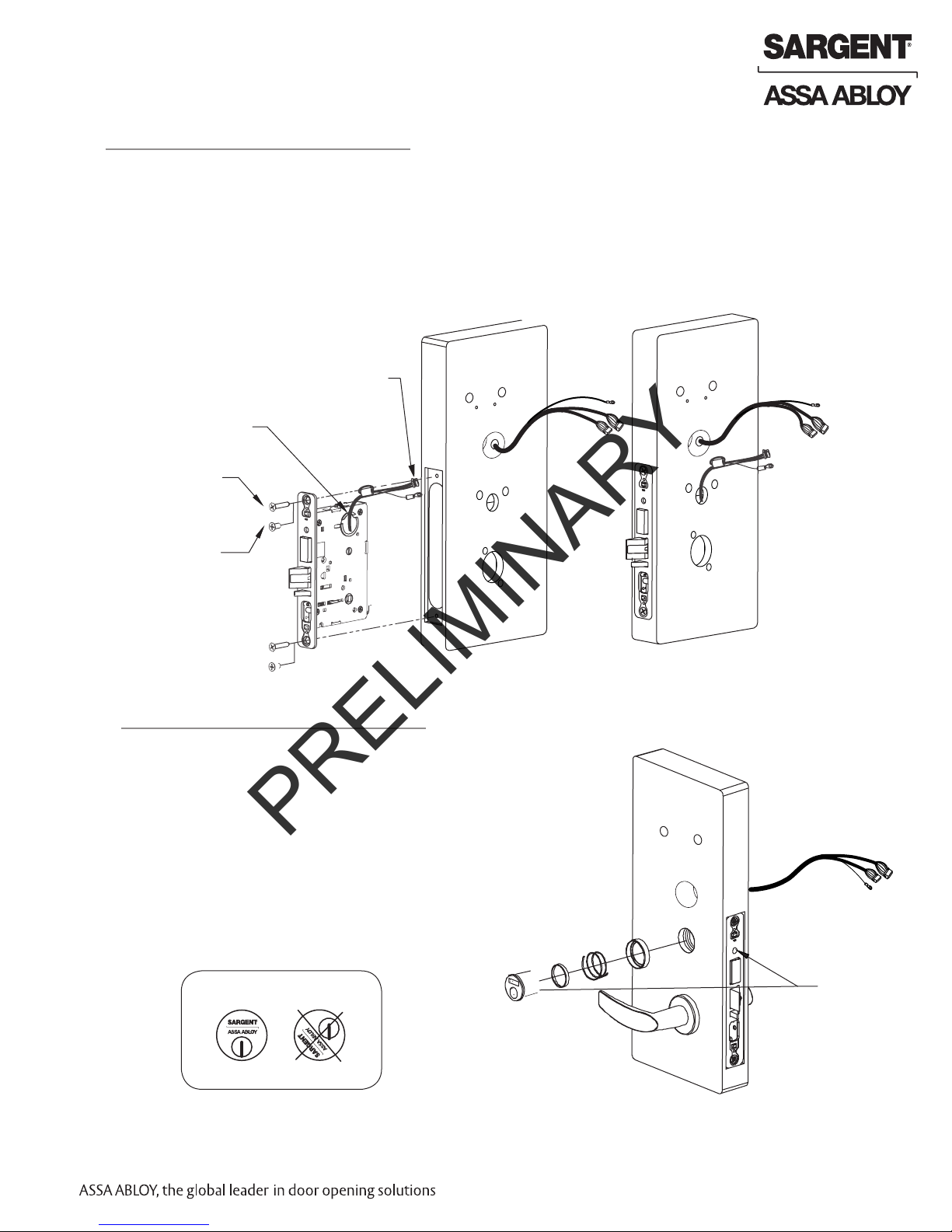
3
Install Lock Body
1. Feed the wires first through the mortise pocket
and out the inside prep, followed by the
lockbody (Fig. 3A).
2. The wires from the lockbody exit the inside
door prep through the mortise pocket (Fig. 3B).
3. Loosely secure the lockbody in the door with
two #12 x 1-1/4” wood screws or
#12-24 x 1/2” machine screws.
Must feed
the harness first,
followed by
the lock body.
Feed wire
into mortise slot.
PoE Cables
Fig. 8A
(2) #12 x 1-1/4” Long
Flat Head Wood Screw
for Wood Doors
(2) #12-24 x 1/2” Long
Flat Head Machine Screw
for Metal Doors
4
Install Cylinder
Fig. 3A
1. Slide cylinder through the spring and rosette/collar and screw into lockbody, rotating the cylinder clockwise.
Cylinder should be flush with rosette/collar.
Note: SARGENT logo must be horizontal
and on the top of the cylinder (Fig. 4B).
2. Secure the cylinder by tightening cylinder
clamp screw located above the deadbolt.
3. Using the key, verify that the key retracts
the
latchbolt (and deadbolt).
Position cylinder so that the SAR-
GENT logo is right-side up.
Mortise Lock Body
Connector and Ground
Ring Terminal
Fig. 3B
Align cylinder groove
with tapped hole,
then tighten set screw
to hold lock cylinder.
Correct Incorrect
Fig. 4B
1-800-810-WIRE • www.sargentlock.com • A8032D 13
Copyright © 2010, Sargent Manufacturing Company, an ASSA ABLOY Group company. All rights reserved.
Reproductions in whole or in part without express written permission of Sargent Manufacturing Company is prohibited.
12/15/10

Passport 1000 Series P1 PoE Mortise Lock
PRELIMINARY
5
Install Inside and Outside Levers
1. Slide the outside lever and spindle assembly through the door and lockbody.
2. Using the inside adapter plate and spindle, secure loosely with (2) #8-32 screws.
Note: Position threaded hole on the inside adapter to align with lever hole.
3. Tighten the lockbody screws on edge of door.
4. After the lockbody screws are tightened, tighten both inside adapter screws.
5. Position and attach rose over inside adapter.
6. Position and secure inside lever to the
inside adapter with set screw.
PoE Cables
Outside Lever Assembly
Fig. 5A
6
Deadbolt Functions Only (82276 & 82277)
1. Insert alignment tool (supplied) into lock body thumb
turn.
2. Slide back plate over tool and make level.
3. Secure back plate to door with two (2) #6 x 3/8”
round head
wood screws or #6-32 x 3/8” round head machine
screws.
4. Dispose of tool, position thumb turn over back plate
(Fig. 6A) and secure with #6-32 x 1/4” flat head
screw.
Note: Thumb turn should cover screw head when
deadbolt is retracted.
Refer to instructions (A5675G) included in package
included with lock.
Mortise Lock Body
Connector and Ground
Ring Terminal
Rose
Inside Adapter Plate
Inside Lever
Back Plate
#6 x 3/8” Round Head
Wood Screws
#6-32 x 3/8" Round
Head Machine Screws
Thumb Turn
Copyright © 2010, Sargent Manufacturing Company, an ASSA ABLOY Group company. All rights reserved.
Reproductions in whole or in part without express written permission of Sargent Manufacturing Company is prohibited.
Fig. 6B Detail
12/15/10
14 1-800-810-WIRE • www.sargentlock.com • A8032D
#6-32 x 1/4"
Flat Head Screw

Passport 1000 Series P1 PoE Mortise Lock
PRELIMINARY
7
Install Gasket (Optional)
Note: Optional, for non-fire rated doors only.
For non-fire rated door applications, an optional gasket may be
used as a weather seal between the escutcheon and the outside
door surface.
Peel off adhesive backing and attach to outside escutcheon.
Gasket
Outside
Passport
Trim
8
Install Outside Escutcheon and Mounting Plate Assembly
1. Insert the mounting posts through holes as shown.
2. On the inside of the door, position the mounting plate
over the indicated holes.
3. Feed PoE and reader cables through side opening (Fig. 8A).
Cable from lockbody feeds from bottom (Fig. 8A and 8B).
4. Attach 2 ground ring terminals, one from controller and
one from lock body to bottom right corner using one
#8-32 x 1-7/8” flat head machine screw.
Make sure they are positioned upright (Fig. 8A).
5. Insert other three #8-32 x 1-7/8” flat head machine
screws and tighten, fastening the outside escutcheon
to the door (Fig. 8B).
IMPORTANT: If the following step is skipped,
Lockbody Cables
the product will not be UL-compliant:
6. Attach two (2) #8 x 3/8” flat head wood screws for
wood doors or (2) #8-32 x 3/8” flat head machine
screws for metal doors (Fig. 8C).
Mounting Plate
(4) #8 - 32 x 1-7/8”
Flat Head
Machine Screws
Reader cable (iCLASS
only)
Outside
Passport
Trim
a
Fig. 8B
PoE Reader Cables
Attach ground wires to
bottom right screw
Controller /
Reader
Cables
Lock Ground
Fig. 7A
Reader cable (iCLASS only)
f
b
c
d
e
10-pin from lock body
a
b
(2) 4-Pin PoE
connectors
c
d
24-pin from reader
Ground wires and PoE and
e
Lock body harnesses
f
Reader cable (iCLASS only)
Fig. 8C
Reader cable
(iCLASS only)
Position
ground ring
terminal
upright,
then
tighten
screw.
(2) #8 - 3/8”
Flat Head
Wood Screws OR
(2) #8 - 3/8”
Flat Head
Machine Screws
Copyright © 2010, Sargent Manufacturing Company, an ASSA ABLOY Group company. All rights reserved.
Reproductions in whole or in part without express written permission of Sargent Manufacturing Company is prohibited.
1-800-810-WIRE • www.sargentlock.com • A8032D 15
12/15/10

Passport 1000 Series P1 PoE Mortise Lock
PRELIMINARY
9
Install Inside Module Component Assembly
Insert bottom of Module Component Assembly first (Fig.
9A), then clip top of Assembly to backplate, verifying
both tabs attached securely.
Tabs
Outside of Door
Fig. 9A
10
Attach Connectors
Secure the following connectors onto the circuit board (Fig.
10A and 10B):
1. Secure the 10-pin lock body assembly connector (e).
2. Secure the 24-pin keypad/card reader connector (d).
3. Secure two 4-pin PoE connectors (b and c).
4. Secure the iCLASS reader cable (f).
Route wires from behind backplate through battery compartment.
Notes:
• Connectors go on only one way.
• Do not force and do not offset connectors.
• Be sure the connectors are completely seated (flush).
b
c
b
f
d
Copyright © 2010, Sargent Manufacturing Company, an ASSA ABLOY Group company. All rights reserved.
Reproductions in whole or in part without express written permission of Sargent Manufacturing Company is prohibited.
e
(2) 4-Pin PoE
connectors
c
d
24-pin from reader
e
10-pin from lock body
f
9-pin reader cable (iCLASS only)
Detail 10B
12/15/10
16 1-800-810-WIRE • www.sargentlock.com • A8032D

Passport 1000 Series P1 PoE Mortise Lock
PRELIMINARY
11
Install Inside Escutcheon
1. Position inside escutcheon as shown (Fig. 11A).
Verify that all wires are positioned within the
escutcheon
to avoid pinching.
2. Attach escutcheon with (2) #8-32 x 1/2”
T-20 Torx pan head screws.
3. Straighten escutcheon and tighten securely.
DO NOT OVERTIGHTEN.
(2) #8-32 x 1/2”
Torx Screws
12
Attach Outside Front Plate
Attach front plate with (2) #8-32 X 1/4” flat head
screws (Fig. 12A).
Fig. 11A
(2) #8-32 x 1/4”
Flat Head Screws
1-800-810-WIRE • www.sargentlock.com • A8032D 17
Fig. 12A
Copyright © 2010, Sargent Manufacturing Company, an ASSA ABLOY Group company. All rights reserved.
Reproductions in whole or in part without express written permission of Sargent Manufacturing Company is prohibited.
12/15/10

Passport 1000 Series P1 PoE Mortise Lock
PRELIMINARY
9
Operational Check
IMPORTANT: Be sure to test functions prior to closing door.
In all cases, perform the following checks:
1. Ensure that inside lever retracts latch (and deadbolt for deadbolt functions).
• For units with cylinders, the following checks apply:
Insert key into cylinder and rotate:
a. There should be no friction against lock case, wire
harness, or any other obstructions. If friction or binding occurs, re-adjust cylinder and wiring harness to
eliminate issues.
b. The key should retract the latch and the key should
rotate freely.
c. The key should extend and retract the deadbolt.
• For units without a keypad, add card using LCT
software and test.
• For units with a keypad, add pin and card using LCT
software and test.
2. LED signalling:
• After using a valid credential, a green flash followed by
three fast amber flashes indicates a low power condition.
Check the input voltage.
If the input voltage is low, disconnect the lock from the
power source and check the power source
voltage. If the power source voltage is correct,
inspect the lock wiring for a possible short.
• If the lock loses power, it will flash rapid amber
for approximately one minute.
After that, the lock will no longer be functional.
3. When you have completed the tests, close the door, ensuring
latchbolt and deadbolt fully extend into strike plate without
binding.
Copyright © 2010, Sargent Manufacturing Company, an ASSA ABLOY Group company. All rights reserved.
Reproductions in whole or in part without express written permission of Sargent Manufacturing Company is prohibited.
12/15/10
18 1-800-810-WIRE • www.sargentlock.com • A8032D

SARGENT Manufacturing
PRELIMINARY
100 Sargent Drive
New Haven, CT 06511 USA
800-810-WIRE (9473) • www.sargentlock.com
Founded in the early 1800s, SARGENT® is a market leader in locksets, cylinders, door closers, exit devices,
electro-mechanical products and access control systems for new construction, renovation, and replacement applications.
The company’s customer base includes commercial construction, institutional, and industrial markets.
Copyright © 2010, Sargent Manufacturing Company, an ASSA ABLOY Group company. All rights reserved.
Reproduction in whole or in part without the express written permission of Sargent Manufacturing Company is prohibited.
ASSA ABLOY is the global leader in door opening solutions, dedicated to
satisfying end-user needs for security, safety and convenience.
A8032D -12/10
 Loading...