


PN# 500-16900
Rev. A.2, 10/03
SECURITRON MODEL DK-26 DIGITAL KEYPAD
TABLE OF CONTENTS AND GUIDE TO THIS MANUAL
The DK-26 is a powerful and versatile product with many features and modes of operation. In most applications you will use only some of these features so this table of contents includes a description of the type of application that applies to each different section. By studying it first, you can save considerable time by skipping over those parts of the manual that don't apply to your application.
SECTION 1. |
DESCRIPTION -------------------------------------------------------------------- |
Page 1 |
SECTION 2. |
PHYSICAL INSTALLATION --------------------------------------------------- |
Page 1 |
SECTION 3. |
WIRING------------------------------------------------------------------------------ |
Page 3 |
SECTION 3.1 POWER SELECTION ---------------------------------------------------------- |
Page 3 |
|
This section explains the power that must be used and gives you power consumption figures.
SECTION 3.2 |
CONNECTING THE KEYPAD CABLE TO THE CPU BOARD |
-----Page 3 |
SECTION 3.3 |
POWER AND ELECTRIC LOCK WIRING-------------------------------- |
Page 3 |
This section introduces the different basic wiring schemes generally required for electric strike control (no exit switch needed). The three sections below provide separate drawings and descriptions depending on your power source and on the power required by the lock.
SECTION 3.3.1 AC LOCK WITH AC POWER --------------------------------------------- |
Page 3 |
SECTION 3.3.2 DC LOCK WITH AC POWER --------------------------------------------- |
Page 5 |
SECTION 3.3.3 DC LOCK WITH DC POWER --------------------------------------------- |
Page 6 |
SECTION 3.4 USE OF THE “F” TERMINAL ----------------------------------------------- |
Page 7 |
The “F” terminal is mainly used for convenient connection of fire alarm contacts which will release a fail safe lock in the event of activation of the fire alarm.
SECTION 3.5 ADDING OTHER LOCK CONTROL SWITCHES----------------------- |
Page 7 |
This section and drawing show proper connection for an external switch such as from Securitron’s Lock Control Panel.
SECTION 3.6 THE REX FUNCTION ---------------------------------------------------------- |
Page 8 |
When you are using a magnetic lock or solenoid bolt, you often require a separate switch to allow egress. This switch can be connected to the CPU board to provide timed egress in different ways. This section fully covers this requirement.
SECTION 4. PROGRAMMING ----------------------------------------------------------------- |
Page 10 |
SECTION 4.1 FIXED PROGRAMMING ------------------------------------------------------ |
Page 10 |
Fixed programming is for lower security applications when the code is not expected to need regular changing by the user. The “Hard” code is used for this requirement.
© Copyright, 2003, all rights reserved • Securitron Magnalock Corp., 550 Vista Blvd., Sparks NV 89434, USA Tel: (775) 355-5625 • (800) MAGLOCK • Fax: (775) 355-5636 • Website: www.securitron.com
An ASSA ABLOY Group company
Rev. A.2. 10/03
SECTION 4.2 KEYPAD CHANGEABLE PROGRAMMING----------------------------- |
Page 12 |
This section explains how to set up easy code change from the keypad by employing a Program code which is relatively constant and a User code which is often changed for better security.
SECTION 4.2.1 CHANGING THE USER AND PROG. CODE FROM KEYPAD --Page 13
This details the code changing procedure that should be taught to the end user.
SECTION 4.2.2. ADDING MULTIPLE USER CODES------------------------------------ |
Page 14 |
The previous two sections explain how to set up keypad changeable programming for the common requirement of a single User code. Up to 59 separate User codes can be added to memory so that individuals or groups can have their own code. This section explains the procedure.
SECTION 4.3 “MASTERKEY” USE OF THE HARD CODE---------------------------- |
Page 14 |
The Hard code is normally used for “fixed” programming but in a multiple door installation, it can be used as a “masterkey” code which will open all doors.
SECTION 4.4 |
SUBSET CODES---------------------------------------------------------------- |
Page 15 |
This section must be read for all multiple code installations. |
|
|
SECTION 4.5 |
DELETING CODES------------------------------------------------------------- |
Page 15 |
This section is most important for multiple code installations but should at least be scanned for all installations as it explains all code deletion procedures.
SECTION 4.6 SETTING THE TIME RANGE AND TOGGLE MODE ----------------- |
Page 16 |
As factory set, the DK-26 will release the lock for five seconds. This section explains how to change that setting and enable “toggle” mode where successive code entries will energize and then deenergize the lock control relay.
SECTION 5. CHANGING LED AND BEEPER OPERATION--------------------------- |
Page 16 |
Special commands can be sent to the CPU board from the keypad to change the way the beeper and LED’s function.
SECTION 6 USE OF THE PROGRAMMABLE RELAY---------------------------------- |
Page 17 |
The CPU board has a second relay that can be assigned to any of several functions which are explained in the following sections. These are enhancements to a standard installation and are therefore not always used.
SECTION 6.1 DOORBELL FUNCTION ------------------------------------------------------ |
Page 17 |
Pressing the “Bell” key will energize the programmable relay which can be used to summon someone to the door.
SECTION 6.2 DURESS FUNCTION ---------------------------------------------------------- |
Page 17 |
This section applies only in high security applications where you require the user to be able to activate a silent alarm if someone is forcing him to open the door via the Keypad. The programmable relay is used to send this signal.
Rev. A.2. 10/03
SECTION 6.3 ANTI-TAMPER ALARM FUNCTION --------------------------------- |
Page 18 |
Someone entering 16 wrong digits while attempting to guess the code will activate the programmable relay.
SECTION 6.4 |
DOOR PROP ALARM FUNCTION ----------------------------------------- |
Page 18 |
The programmable relay will activate if the door is left open too long. |
|
|
SECTION 6.5 |
NIGHTLIGHT FUNCTION----------------------------------------------------- |
Page 19 |
The programmable relay will activate for five seconds when any key is pressed. This can be used to turn on a lamp (not supplied) for operation in the dark.
SECTION 7 ADDITIONAL HARD WIRED OPTIONS------------------------------------- |
Page 19 |
The sections that follow discuss additional ways to use the DK-26. |
|
SECTION 7.1 DUAL PAD OPERATION ----------------------------------------------------- |
Page 19 |
This section applies if you want to use two Keypads reporting to one CPU Board for digital control of entry and exit.
SECTION 7.2. HARD WIRED CODE DISABLING ---------------------------------------- |
Page 19 |
Through the use of jumpers or external switches you can disable the Hard code and/or all User codes. This is generally used with a time clock for day/night operations.
SECTION 7.3 |
ALARM SYSTEM SHUNTING----------------------------------------------- |
Page 20 |
The DK-26 can shunt an active alarm point for authorized entry. |
|
|
SECTION 7.4 |
ANTI-TAILGATING------------------------------------------------------------- |
Page 20 |
With this feature, you can abort the DK-26’s timer once the door is opened to make sure only one person enters.
SECTION 7.5 WIRING WITH TOUCH SENSE BAR AND MAGNALOCK ---------- |
Page 20 |
This section provides a drawing for a popular combination of Securitron products.
APPENDIX A COMMAND SUMMARY ------------------------------------------------------- |
Page i |
This section lists all possible command sequences that can be sent to the unit when it is in program mode. These commands are referenced throughout the manual as they apply to different requirements.
APPENDIX B TROUBLE SHOOTING -------------------------------------------------------- |
Page ii |

Rev. A.2, 10/03 |
Page-1 |
SECURITRON MODEL DK-26 DIGITAL KEYPAD
INSTALLATION & OPERATING INSTRUCTIONS
1. DESCRIPTION
Securitron's DK-26 is a digital keypad system designed for medium/high security control of electric locks. It consists of two components: the keypad and the CPU board connected by a 16 ft. cable. This allows the CPU board to be mounted within the protected area for higher security. Tampering with or even destroying the keypad will not release the door. The rugged stainless steel keypad may be mounted outdoors in any environment as it is fully weatherproof. The keypad features true 10 digit operation (keys are not paired), three LED’s and a beeper.
2. PHYSICAL INSTALLATION
The first step is to plan the physical location of the two components. The keypad is normally surface mounted on the outside of the door to be controlled, and the CPU Board is mounted inside the protected area safe from tampering.
To install the keypad, holes must be drilled for the 2 mounting screws and the cable. A template is not provided due to unavoidable variations on the cable exit of each keypad. Referring to Figure 1, note that the top screw engages the slot at the top of the keypad. Once the top screw has been installed, the location of the cable hole should be set roughly by positioning the keypad and marking the cable hole point. Make sure the keypad is pulled down firmly on to the screw. A 3/8" (10MM) hole is then drilled for the cable. After the cable has been pulled through, the final screw secures the keypad to the wall. Note that 2 alternate bottom screws are supplied with the unit. One is a #10 spanner head for improved tamper resistance. Alternately the #8 Phillips standard screw may be used. After this, peel the backing of the enclosed Securitron DK-26 label and affix it to the bottom of the keypad covering the head of the screw. This not only improves the appearance of the keypad but helps foil casual vandalism. Note finally that a blank rectangular label has also been furnished. This can be used to cover up the “BELL” legend if you don’t intend to utilize the doorbell function and are concerned that people will press the BELL key and expect someone to come to the door.

Rev. A.2, 10/03 |
Page-2 |
FIG. 1: PHYSICAL INSTALLATION OF KEYPAD
MOUNTING
SURFACE
CABLE 
(1) MOUNT SCREW TO ENGAGE SLOT AT TOP OF KEYPAD
DRILL 1/8" (3MM) HOLE
(2)DRILL 3/8" (10MM) HOLE FOR CABLE
(3)SECURE BOTTOM WITH SECOND SCREW. COVER SCREW HEAD WITH "DK-26" LABEL.
DRILL 1/8" (3MM) HOLE
NOTE: CHOOSE PHILIPS OR SPANNER (TAMPER) HEAD SCREW
The CPU Board is furnished in a snap-apart steel enclosure with the board itself mounted on plastic snap-trak. The CPU Board must be installed in a dry location free of extremes of temperature and humidity. If the 16 ft., twelve conductor cable that is included is not of sufficient length, additional cabling can be spliced by the installer. However, a long cable run can give rise to electronic noise problems in certain environments. It should therefore be avoided where possible and in no case should cable length exceed 100 ft. (30 meters).
Cable entry to the CPU board enclosure can be handled in one of two ways. There is a hole in the bottom of the enclosure, the use of which creates the most attractive installation as the cable is completely hidden. Alternately, there is a side knockout in the enclosure cover which permits surface mounting of the cable. The side knockout also permits a wiring technique which is convenient when the CPU board enclosure is to be mounted in an awkward location such as above a drop ceiling. You can pop the board itself out of its snap track and make all your connections with the board in your hands. The board is then re-snapped into the plastic trak. The enclosure cover snaps on with the wires emerging from the side knockout. If you use this technique, avoid touching the components or rear pins on the board as much as possible. Static electricity can destroy the processor. Also when you snap the board back in its track, make sure it’s securely done. Sometimes you need to squeeze the outer lips of the track to insure that the board edges are really seated in the slot.
Rev. A.2, 10/03 |
Page-3 |
3. WIRING
3.1 POWER SELECTION
The DK-26 operates on 12 to 24 volts AC or DC. Nearly all electric locks operate on voltage within this range, so the power supply you would normally utilize to operate the electric lock will also operate the DK-26. Power consumption of the DK-26 depends on voltage and is shown on the following chart:
DK-26 POWER CONSUMPTION: |
12 VOLTS |
24 VOLTS |
REST STATE (MIN) |
7 mA |
20 mA |
RELAYS, LED’S, + BEEPER ON (MAX) |
160 mA |
190 mA |
Be sure that your power source is of adequate capacity to operate both the lock and DK26. If the installation is "under-powered", the voltage of the supply will drop rapidly when the lock is energized and this can crash the microprocessor.
3.2 CONNECTING THE KEYPAD CABLE TO THE CPU BOARD
There are 12 color coded wires in the keypad cable. Refer to Figure 2 and connect each wire to the indicated terminal on the CPU Board. No other connections may be made to these terminals (except if two keypads are used with one CPU board).
3.3 POWER AND ELECTRIC LOCK WIRING
The wiring scheme for electric lock control varies depending on the type of lock and the desired control. The following sections provide drawings and explanations for different types. One general point is that the DK-26’s lock control relay has 5 Amp contacts. Most electric locks draw much less. If, however, you are using a specialty lock which draws more than 5 Amps or has a higher in-rush current, purchase a high current relay and use the DK-26’s contacts to switch this relay while using its high capacity contacts to switch the lock. Note finally that the DK-26 includes additional options which are covered in Sections 6 and 7. To determine the complete wiring for your installation, begin with the drawings shown in Section 3 and then check Sections 6 and 7 to see if you will require any of the additional features.
3.3.1 AC LOCK WITH AC POWER
This is the simplest installation possible with the DK-26. A fail secure lock operating on AC is used. This is generally an electric strike. “Fail secure” means that the lock is secure when it is not powered. Power is applied to release the lock. Referring to figure 3, select a transformer of the same output voltage as the lock (12 or 24 VAC). Make sure the capacity of the transformer is large enough to operate both the DK-26 and the lock and that the transformer is UL listed under the UL 294 standard (to maintain the DK-26 UL listed status). The two transformer secondary wires connect to the “AC input” terminals as shown (there is no polarity with AC). Power from one terminal then goes to the common of relay #1. The NO contact of relay #1 will power the lock (releasing the door) when a correct code is entered. Note that AC locks are normally all fail secure. If you come across a fail safe AC lock (secure when powered) you would merely make the connection to the lock from the NC1 rather than NO1 terminal.

Rev. A.2, 10/03 |
Page-4 |
FIG. 2: OVERVIEW OF CPU BOARD
|
|
|
|
|
|
|
|
|
|
|
|
KEYPAD CABLE |
|
|
|
|
|
|
|
|
|
|
|
|
|
|
|
|
||||||
|
|
|
|
|
|
|
|
|
|
|
|
VIOLET |
|
PINK |
|
ORANGE |
|
BEIGE |
|
BROWN |
|
GRAY |
|
BLACK |
|
WHITE |
|
BLUE |
|
RED |
|
YELLOW |
|
GREEN |
|
|
|
|
|
|
|
|
|
|
|
|
|
|
|
|
|
|
|
|
|
|
|
||||||||||||
|
|
|
|
|
|
|
|
|
|
|
|
KEYS |
|
KEYS |
|
KEYS |
|
KEYS |
|
KEYS |
|
KEYS |
|
KEYS |
|
COMMON |
|
BEEPER |
|
LED RED |
|
LED YEL |
|
LED GRN |
|
|
|
|
|
|
|
|
|
|
|
VIO |
PNK |
BGEORG |
BRN |
GRY |
BLK |
WHT |
BLU |
RED |
YEL |
GRN |
|||||||||||||
|
|
|
|
|
|
|
|
|
|
|
|
|
|
|
|
|
|
|
|
|
|
|
|
|
|
|
|
|
|
|
|
|
|
|
|
|
|
|
|
|
|
|
|
|
|
|
|
|
|
|
|
|
|
|
|
|
|
|
|
|
|
|
|
|
|
|
|
|
|
|
|
|
|
|
|
|
|
|
|
|
|
|
|
|
|
|
|
|
|
|
|
|
|
|
|
|
|
|
|
|
|
|
|
|
|
|
|
|
|
|
|
|
|
|
|
|
|
|
|
|
|
|
|
|
|
|
|
|
|
|
|
|
|
|
|
|
|
|
|
AC |
PS3 PS2 PS1 |
12/24 AC POWER |
|
IN |
|
FREE TERMINAL
12/24 DC NEGATIVE
12/24 DC POWER +
DC TERMINALS MAY ALSO BE USED AS OUTPUT TO POWER DC LOCK, IF AC POWER IS SUPPLIED
|
|
F |
|
|
|
|
|
|
|
|
|
|
||
|
|
DC |
|
|
|
|
|
|
|
|
|
|
||
|
|
|
|
|
|
|
|
|
|
|
||||
+IN/OUT |
|
|
|
|
|
|
|
|
|
|
||||
|
|
|
|
|
|
|
|
|
|
|
|
|
||
|
|
|
|
|
|
|
|
|
|
|
|
|
|
|
|
|
PRGM |
HARD |
|
SRC |
REX |
UCD |
|||||||
|
|
CODE |
CODE |
|
||||||||||
|
|
|
MODE PROGRAM SET TO PUSH |
|
CODE HARD PROGRAM TO PUSH |
|
|
|
|
|
|
|
||
|
|
|
|
|
|
|
|
|
|
|
||||
|
|
|
|
|
TERMS HCD UCD, REX, FOR .COM |
RELEASE) (REMOTE INPUT REX |
CODES USER ALL DISABLE |
|||||||
MICROPROCESSOR
AUX.
SOCKET
SPDT |
DPDT RELAY |
RELAY |
HCD  NCX CX NOX
 NC2 C2 NO2
  NC1 C1 NO1
DISABLE |
|
|
RELAY CONTACTS |
RELAY |
|||
|
PROGRAM |
LOCK CONTROL |
|
CODE HARD |
CONTACTS |
|
|
|
|
|
|

Rev. A.2, 10/03 |
Page-5 |
Note installation of the MOV across the power wires to the lock. The MOV is the small black disk shaped component furnished loose with the DK-26. Its function is to absorb inductive kickback from the lock’s coil. Without the MOV, this kickback voltage will arc over the relay contacts and reduce the switching life of the relay. The arc also creates electronic noise which could occasionally cause the microprocessor to malfunction. The MOV should be spliced into the lock power wires as close to the lock as possible.
FIG. 3: AC LOCK - AC POWER WIRING
TRANSFORMER
12 OR 24 VAC
|
|
AC |
|
|
IN |
|
|
F |
|
|
IN DC |
|
|
|
|
|
|
+ |
/OUT |
|
|
||
NC1 C1 NO1 |
|
|
AC FAIL SECURE |
|
|
||
|
|
||
|
MOV |
LOCK |
|
3.3.2 DC LOCK WITH AC POWER
For convenience and economy, most DC electric locks can be operated from an AC transformer when the DK-26 is used. Select a transformer of the same voltage as the lock (12 or 24). The CPU board converts the input AC to DC to operate the lock. Make sure the capacity of the transformer is large enough to operate both the DK-26 and the lock and that the transformer is UL listed under the UL 294 standard (to maintain the DK-26 UL listed status). The lock must accept full wave rectified DC power. This is true of most DC locks (including Securitron’s Magnalocks) but some specialty units require regulated DC power. You must operate those as described in the next Section. Note finally that many DC lock installations call for battery backup. To achieve this, you must employ a DC battery backup power supply and also follow the wiring description in Section 3.3.3.
DC locks come in “fail secure” and “fail safe” versions. A fail secure lock is secure when not powered and a fail safe lock is secure when powered. All magnetic locks are fail safe. Figure 4 shows AC power being input to the AC terminals. The DC terminals furnish output power for the lock. DC locks operated in this way must not draw more than 2 Amps. The positive DC terminal connects to the common of relay #1 and either the NO1 terminal (if the lock is fail secure) or the NC1 terminal (if the lock is fail safe) connects to the lock’s positive power input. This is shown in dotted lines. You only connect one of these terminals. Note that some DC locks are polarized and you must connect lock power correctly to positive and negative. Others are not polarized and can be connected either way. Consult the lock instructions.
Note installation of the MOV across the power wires to the lock. The MOV is the black disk shaped component furnished loose with the DK-26. Its function is to absorb inductive kickback from the lock’s coil. Without the MOV, this kickback voltage will arc over the relay contacts and
Rev. A.2, 10/03 |
Page-6 |
reduce the switching life of the relay. The arc also creates electronic noise which could cause the microprocessor to malfunction. The MOV should be spliced into the lock power wires as close to the lock as possible. Some DC electric locks have internal kickback protection including all Securitron Magnalocks. You don’t need the MOV for these locks but if you are not sure, it does no harm to install the MOV so long as the lock power is in the 12-24 volt range.
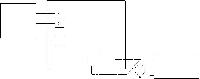
FIG. 4: DC LOCK - AC POWER WIRING
TRANSFORMER
12 OR 24 VAC
|
|
AC |
|
|
IN |
|
|
F |
|
|
IN DC |
|
|
|
|
|
|
+ |
/OUT |
|
|
||
|
NOTE: MOV NOT REQUIRED IF |
|
|
SECURITRON MAGNALOCK IS USED |
|
NC1 C1 NO1 |
IF FAIL SECURE |
DC FAIL SECURE |
+ |
||
|
MOV |
OR FAIL SAFE LOCK |
IF FAIL SAFE |
|
|
|
|
|
3.3.3 DC LOCK WITH DC POWER
Select a power supply of the same voltage as the lock (12 or 24). Make sure the capacity of the supply is large enough to operate both the DK-26 and the lock. The DK-26 does not require regulated power but certain specialized electric locks do, so follow the rule of matching the power supply to the requirements of the lock.
DC locks come in “fail secure” and “fail safe” versions. A fail secure lock is secure when not powered and a fail safe lock is secure when powered. All magnetic locks are fail safe. Figure 5 shows correct wiring. The positive DC terminal connects to the common of relay #1 and either the NO1 terminal (if the lock is fail secure) or the NC1 terminal (if the lock is fail safe) connects to the lock’s positive power input. This is shown in dotted lines. You only connect one of these two terminals. Note that some DC locks are polarized and you must be sure to connect the lock power wires correctly to positive and negative. Others are not polarized and it doesn’t matter which way they are connected. Consult the lock instructions.
Note installation of the MOV across the power wires to the lock. The MOV is the small black disk shaped component furnished loose with the DK-26. Its function is to absorb inductive kickback from the lock’s coil. Without the MOV, this kickback voltage will arc over the relay contacts and reduce the switching life of the relay. The arc also creates electronic noise which could occasionally cause the microprocessor to malfunction. The MOV should be spliced into the lock power wires as close to the lock as possible. Some DC electric locks have internal kickback protection including all Securitron Magnalocks. You need not employ the MOV for these locks but if you are not sure, it never does any harm to install the MOV so long as the lock power is in the 12-24 volt range.
 Loading...