

Page 1
PN# 500-10420
Rev. A.3, 5/00
SECURI TRON 32, 34, 62 AND 82 SERIES MAGNALOCK
TABLE OF CONTENTS AND GUIDE TO THIS MANUAL
There are numerous Magnalock version s and n umerous different appl ications exist for them.
Accordingly, this manual provides a broad range of information- only a portion of which is
applicable to any individual use. This manual guide provides a brief summary of many of the
Sections which allows you to consult only the portions of the manual that apply to your
application.
SECTION 1. DESCRIP TION---------------------------------------------------------------------Page 1
SECTION 2. PHYSICAL INSTALLATION---------------------------------------------------Page 1
This is the largest part of the manual with sections that explain the different types of
physical installations which vary according to door or gate types as well as Magnalock
versions.
SECTION 2. 1 SURVEY---------------------------------------------------------------------------Page 1
This section concerns how to pre-plan the installation.
SECTION 2. 2 INSTALLATION TOOL KIT --------------------------------------------------Page 1
This s ec tion expl ains an avail able acc es s or y .
SECTION 2. 3 GENERAL INSTALLATION ON OUTSWINGING DOOR------------Page 1
SECTION 2. 3.1 STRIKE P LATE MOUNTING----------------------------------------------Pag e 1
SECTION 2. 3.2 MOUNTING THE MAGNET------------------------------------------------Page 3
The ab ove three sec tions exp lain t he most common Magn alock in stal lat ion on a d oor th at
swings away from the lock. They also include general mounting instructions and should
therefore b e r ead for all in s tall ations.
SECTION 2. 4 GENERAL INSTALLATION ON INSWINGING DOOR ---------------Pag e 5
This section explains inst al lation of "F" type Magnalocks on inswing in g doors.
SECTION 2. 5 MOUNTING PROCEDURES FOR SPECIFIC DOOR TYPES-------Page 6
The following six sections provide specific advice depending on door type which incl udes
recommended bracketry.
SECTION 2. 5.1 ALUM INUM FRAME GLASS DOOR MOUNTING-------------------Page 6
SECTION 2. 5.2 THE UMB BRACKET FOR ALUMINUM AND CONCRETE ------Page 7
SECTION 2. 5.3 SOLID GLASS DOOR MOUNTING--------------------------------------Page 8
SECTION 2. 5.4 DOUBLE DOOR MOUNTING ---------------------------------------------Page 9
SECTION 2. 5.5 CONCRETE HEADER OR WOOD FRAME MOUNTING ----------Page 9
SECTION 2. 6 MOUNTING THE M AGNALOCK ON EXTERIOR GATES-----------Pag e 10
This section, which includes three drawings, covers outdoor use of the Magnalock on a
variety of g ate types.
SECTION 2. 7 USE OF DRESS COVERS----------------------------------------------------Page 12
This sect ion introd uces the Dres s Cover which is used after p hys ical mou ntin g to im prove
ins tallation ap pearanc e and t am per resistance.
SECTION 2. 8 T AMPER PROOFING T HE MAGNALOCK ------------------------------Pag e 12
This s ec tion sh ould be read for an y instal lation in a high vandalism area.
Ó Copyright, 2000, all rights reserved · Securitron Magnalock Corp., 550 Vist a Blvd., Sparks NV 89434, USA
Tel: (775) 355- 5625 · ( 800) M AG LO CK · Fax: (775) 355- 5636 · Website: www.securitron.com
An ASSA ABL OY Group co m p any
Page 2

Rev. A.3, 5/00
SECTION 3. ELECTRICAL INSTALLATION-----------------------------------------------Page 13
SECTION 3. 1 GENERAL EL E CTRICAL CHARACT E RISTICS -----------------------Page 13
This s ection expl ain s t ech nic all y t h e Magn aloc k's elec tric al ch aract erist ics as a l oad an d is
for reference.
SECTION 3. 2 S TANDARD LOCK -------------------------------------------------------------Page 13
This section explains powering and switching the Magnalock.
SECTION 3. 3 AV OI DING POOR RELEASE CHARACTERIST ICS-------------------Pag e 13
This s ec tion warn s against wiring mistakes s pecific only t o the model 32 series .
SECTION 3. 4 WIRE GAUG E S IZING ---------------------------------------------------------Page 14
This reference section explains how to select wire size for app lications where the l ock is
distant from the power supply.
SECTION 3.5 SENSTAT MAGNALOCKS: “SC”------------------------------------------Page 14
Read this section if you have a Senstat Magnalock.
SECTION 3. 6 DOUBL E DOOR PROCEDURE FOR STATUS REP ORT ING-------Page 15
This section applies if you h ave Senstat locks on a dou ble door an d want them to report as
a single l ock.
SECTION 3. 7 DOUBL E DOOR CONTROL S WITCHI NG --------------------------------Page 15
This section applies whenever you have two locks controlled by a singl e switch.
SECTION 3. 8 E MERGENCY REL E AS E -----------------------------------------------------Page 16
This section should be understood by all installers.
APPENDIX A TROUBLESHOOTING----------------------------------------------------------Page i
Refer to this section before cal l ing the factory on any operating problem.
APPENDIX B CALCULATING WIRE GAUGE S IZING-----------------------------------Page ii
This detailed reference section explains how to select wire gauge in complicated multi-lock
installations.
APPENDIX C CONSIDERATI ONS FOR MAXI MUM P HYSI CAL SECURITY------Page iii
This reference section explains the technical aspects of lock holding force and resistance to
attack. It contains numerous installation techniques which act to insure high lock security. It
must be read for high security applications and also has excellent educational value.
Page 3

Rev. A.3, 5/00
Use of the Magnalock (or any lock) can lead to an unsafe
condition within the building if it is controlled in a manner that
improperly restricts passage through certain doors. The most
important area of concern is to insure that building evacuation is
not im peded in the event of a fire or other em ergency condition.
Consult with the local building or fire department to insure that
the controls installed with the Magnalock create a safe and
code legal installation.
The Magnalock has an unlimited operating life and receives a
great deal of cumulative shock over this life from the door closing
and from persons attempting to open the door when it is
secured. It is therefore vital that it be firmly m ounted to the door
header. If this is not done, a person's use of the door could
cause the m agnet body to fall and possibly cause an inj ury. The
blind nuts furnished with the Magnalock will create strong and
permanent mounting when correctly collapsed inside the
header. If they are not collapsed, an unsafe condition will re sult .
Make sure you understand section 2.3.2 in the manual on
magnet mounting and collapsing the nuts.
- SHOCK HAZARD. The Magnalock must
be operated from a DC power supply of appropriate capacity
and voltage. The DC output of the power supply must not be
connected to earth ground but must be isolated, or a shock
hazard and possible damage to the product could result. All
Securitron power supplies are delivered with isolated DC outputs
and the majority of commercial supplies are also furnished this
way. If you are not certain that the DC outputs of your power
supply are isolated, check with an Ohmmeter between earth
ground and +V, and then between earth and 0V (negative). You
should not have continuity.
Page 4

Rev. A.3, 5/00 Page- 1
SECURI TRON 32, 34, 62 AND 82 SERIES MAGNALOCK
INSTALLATION INSTRUCTIONS
1. DESCRIPTION
Secu rit ron ’s Magnal ock famil y rep resen ts the stat e of th e art in el ect ric l ock ing . Three d if feren t
size models are available: The Model 32 and M odel 34 s eries wit h a h ol d ing f orce of 600 lb s.
(275 Kg. ); Th e Model 62 series with a h old in g forc e of 1, 200 lb s. (550 Kg .) and the model 82
series wit h a h oldin g f orce of 1,800 lbs. (820 Kg.). Several mou nting and electronic options
are available whic h are des c r ibed in this manual. Note that m os t points in this manu al appl y to
the entire Magnalock series. When a point applies to a particular Magnalock version, this will
be specifically noted.
2. PHYSICAL INSTALLATION
2.1 SURV E Y
Becau se of th e wide variety of situ ations in whic h th e Magnal ock m ay b e ut ilized , f irst survey
the physical area in which it is to be installed and determine the best method of mounting it. In
this initial planning two considerations come into play: the mounting method must be strong
enough so that the full holding power of the Magnalock can be effective, and the Magnalock
and wiring must be protected to a reasonable degree from damage by intruders or vandals.
Often an accessory bracket is necessary, either furnished by Securitron or made up by the
install er. The brackets that can be used are covered later. Note that Magnal ocks are supplied
with a complete set of fasteners. When s hipped outside of North America, metric fast eners ar e
supplied and therefore the drawings in this manual show both US and metric fasteners.
2.2 INSTALLATION TOOL KIT
Secu rit ron offers an in st al lat ion tool kit (p art # IK or IKM, for m etr ic u se) wh ich in cl ud es s pec ial
drills, a drilling template, a blind nut collapsing tool and extra fasteners and hardware. If the
install ation is for a larg e n umber of locks or if the installer exp ects to p erform oth er inst al lations,
we recommend the purchase of this kit as it reduces installation labor and improves job quality.
2.3 GENERAL INSTALLATION ON OUTSWINGING DOOR
The Magnalock should be mounted under the door frame header in the corner farthest from the
hinges (see Figure 4). Most commonly, it is positioned horizontally but vertical positioning
sh oul d also be cons ider ed. In some cases f or examp le, th e h oriz ont al head er on an al um inu m
frame glass door is not as strong as the vertical extrusion, so vertical mounting would be
pr eferr ed. This ty pe of in stal l ation p l aces t he Mag nal ock su ch th at th e d oor swin g s away f rom
it. Th is configuration is necessary for all facility exit doors (otherwise, the Magnalock would be
on t he out side of the b uil din g). F or int erior d oors, the Magnal ock shou ld stil l be m ount ed in
this manner unless security planning anticipates a physical assault on the Magnalock from that
sid e of the door in which cas e s ee s ec tion 2.4 on inswingin g door instal lation .
2.3. 1 S TRIKE PLATE MOUNT ING
The strike should be mounted before the magnet on the upper corner of the door. The first
step is to locate the precise place you intend to mount the strike including deciding whether
you want to m oun t th e Magn al ock h orizon t all y or vertical l y (s ee Sect ion 2. 3.2). Th e top of th e
strike should be positioned about 1/10" (2.5mm) below the line where the door meets the
door stop, or below the header if there is no door stop to permit free closing. If the strike is
mounted vertically instead of horizontally, increase this stand-off distance to 2/10" (5mm).
More clear ance is n eeded on a vert ic al mount b ec ause the strike projects out from the door and
can s c r ape the s ide frame as the d oor s wings c losed on its arc . Final posit ioning of the strike is
dictated by the desired position of the magnet. The strike must be centered on the magnetic
poles (3 bars) and th e magnet is n ormally moved an inch or so in (or down) from the frame
corner so that the magnet mounting holes will not have to be drilled awkwardly in the corner.
When the strike position has been chosen, step t wo is to d ril l th ree h ol es in th e d oor f oll owin g
the template. Step three is mounting the white plastic bushings which surround and insulate
the roll pins in to the 1/2" (12.7mm) holes. The bu shing s are employed to insu late th e strike
electrically from a metal door and also help preven t the r oll pins f r om wear ing t he door.
Page 5
Rev. A.3, 5/00 Page- 2
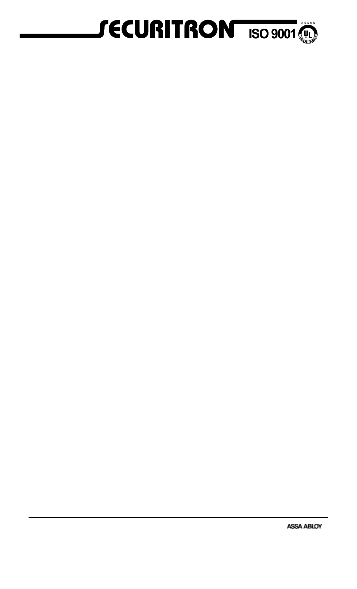
FIG. 1: STANDARD MAGNET DIMENS IONS AND ASSEMBLY
If "G" option is furnished, (62
and 82 series only), the wire
cable emerges from a 3/4"
male; 1/2" female conduit
fitting on the end of the
magnet. The mounting holes
are counterbored from both
sides to make the magnet
non-handed
Blind Nut
PN# BN-250 or
PN# BN-6MM (Metric)
(Pack of 40 with tool)
Gold Washer
PN# FW-1
(Pack of 24)
32 8" 1.88 1.5
(mm) 203 47.8 38.1
34 9.5" 1.75 1.125
(mm) 241 44.5 28.6
62 8" 2.9 1.75
(mm) 203 73.7 44.5
82 12" 2.9 1.75
(mm) 305 73.7 44.5
2
6
l
e
d
o
M
2
3
l
e
d
o
M
Length Width Depth
Recommended Tools:
1/2" or 3/8" Drill Motor
1/8", 3/8", 1/2" Drill Bits
1/2" Open or Crescent Wrench
3/16" Hex Key (Allen Wrench)
Hammer, Center Punch
Masking Tape, Fish Tape or
Leed Wire
Wire Strippers/Cutters
Crimp Wire Connectors
Multi-Meter
1/4-20 x 3" Cap Screw
PN# SCS-35 (Pack of 4)
6mm-1mm x 75mm
PN# 300-12650
Tamper Cap
PN# FC-1
(Pack of 24)
1/4-20 x 2 1/4" Cap Screw
PN# 300-12750 or
6mm-1mm x 55mm
PN# 300-12925
(For Model 32 Magnalock)
Step four is to insert the strike mounting hardware. Roll pins furnished with the strike should
be hammered into th e strike. Be careful not to hit them too hard as it is possible to raise
dents on the strike surface by over driving the pins which degrades strike flatness and
therefore holding force. The strike is secured by the central strike mounting screw. Two
flexible washers are then placed between the strike and the door with the strike mounting
screw passing through the washers to provide flexibility. A third rubber washer is furnished.
This is not normally used but may be employed in case the spacing of the magnet and strike is
a little off. Add ing th e third washer will move the strike closer to the magnet. Do not place t he
washers around the roll pins. The roll pins should "float" in their holes and not bind. Their
only purpose is to p reven t th e strike from rotating or spinning.
In step fi ve, the strike is secured to the door via the supplied sex bolt. Note that we supply a
massive 1 1/4” diamet er sex bol t as it is t he on l y p oin t of att ack f rom t he ou t sid e of t he d oor. It
can be difficult to align the strike mounting screw with the sex bolt, so the following technique
is recommended : Start the sex bolt in its 1/2" (12.7 mm) hole b ut thread t he strike mountin g
screw into it (with strike plate and washers) before hammering the sex bolt down. Next,
hammer the sex bolt d own and then screw the strike mountin g screw in the rest of the way.
This m ak es align m ent much easier .
Step six is to verify proper mounting. When the strike is mounted, make sure it flexes
freely around the washer stack. This flexing allows the Magnalock to pull the strike into
perfect align ment f or maximum hold ing f orce. It is never poss ibl e f or a d oor an d f rame to l in e
up well enough for the Magnalock to function unless the strike is allowed to flex.
Page 6
Rev. A.3, 5/00 Page- 3
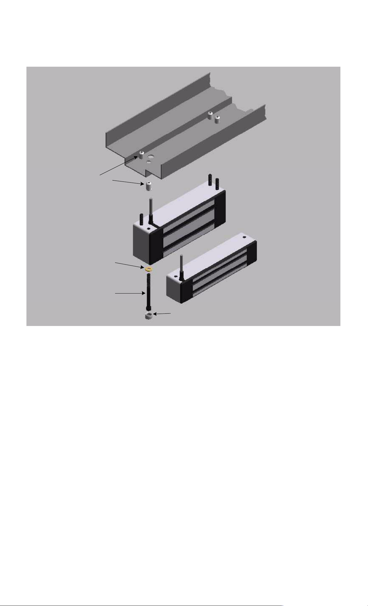
FIG. 2: STRIKE DIMENSIONS AND ASSEMBLY
Sex Bolt, Models 32, 62, 82, PN# SB-1, SB-1M (Metric)
Model 34, PN# 330-12100, 330-12150 (Metric)
R
u
P
N
#
R
b
W
b
e
r
W
a
-
s
1
h
(
P
a
c
k
Bushing (2), PN# 560-12050
e
r
(
2
)
o
f
2
4
)
Roll Pin (2), PN# 330-10800
1/4" x 1 1/4"
Length Width Depth
32 6.25" 1.63 .5
(mm) 158.8 41.4 12.7
34 6.4" 1.44 .44
(mm) 164.5 37 11.3
62 6" 2.75 .5
(mm) 152.4 70 12.7
82 9.5" 2.75 .5
(mm) 240 70 12.7
Flathead Screw
5/16-18 x 1 3/4"
PN# 300-13600 or
8mm-1.25mm x 40mm
PN# 300-13750 (Metric)
Bushing,
PN# 330-12000
2.3.2 MOUNTING THE MAGNET
Step one is to locate the mounting position of the magnet. It will mount in the door frame
header with four soc k et cap mac hine sc r ews for metal fram es or wood sc r ews for wood frames.
In mounting the Magnalock, six conditions must be followed:
-- The frame header mus t present a fl at surface for th e magnet to mount to. 1 7/8” (48mm) for
the model 34, 2 1/4” (57mm) for the model 32 and 2 1/2" (63.5mm) for the model 62 an d 82 are
req uired f r om the door to the rear of the magnet f or prop er mountin g (as shown in Fig ure 4) . If
th is len g th of flat surf ace is n ot avail abl e, th e u se of stop filler plates and/or head er bracket s
availab le from Securitr on can usually r es olve the probl em . Again, r efer to Figure 4.
-- The frame area selected must be structurally strong enough to yield a properly secure
ins tal l ation . Th e issu e of fram e str eng t h m us t b e c ons ider ed in sel ectin g vertical or hor izon tal
mounting. One often finds on aluminum headers that the horizontal extrusion is weak and can
be snapped off, so vertical mounting would be preferred. It is also possible to reinforce the
head er b y ad d in g a s teel p lat e. Th e in stal l er mu st avoid mou n tin g t h e m agn et t o a wob b l y or
weak support or the intrinsic security of the lock will be diminished.
-- The magnet face must be parallel to the strike plate.
-- The magnetic poles (three metal bars on the Magnalock), must be centered on t he strike.
-- The magnet must make solid contact with the strike but still allow the door to close
properly.
-- Th e direction of door opening must p ull the st r ik e d irect ly aw ay from the magnet rather than
sl iding it away. Electromagnet s hold only weak ly in the shear direc tion of pul l.
On ce a solid fl at sur face has been p repar ed for t he mag net, it mu st be posit ioned so that its
face is parallel an d centered to the strike pl ate. When th e magnet has been experimentally
positioned this way, it's ready for mounting.
Page 7
Rev. A.3, 5/00 Page- 4
In step two, hol es mu st be drilled for the mounting screws, and a 1/2" (12.7mm) d iameter wireway hole should be drilled. Step three is to install the blind finishing nuts. For proper
strengt h, the 1/4-20 (or 6mm) mountin g machine screws must be secured by t hese nuts. They
will work on any th ickn ess metal header and are used as fol lows: A 3/8" (9.5 mm) hole is drilled
following the template for each nut. The nut is then pressed u p into the hole and lightly seated
with a hammer tap. The nut is then collapsed inside the header. If you have Securitron's IK
ins tallation kit , the nut s m ay be collapsed by t he use of the blin d nut placem ent tool. A s pecial
collapsing tool is also included with each Magnalock. It is somewhat slower to use than the
more elaborate tool found in the installation kit. For its use, see Figure 3.
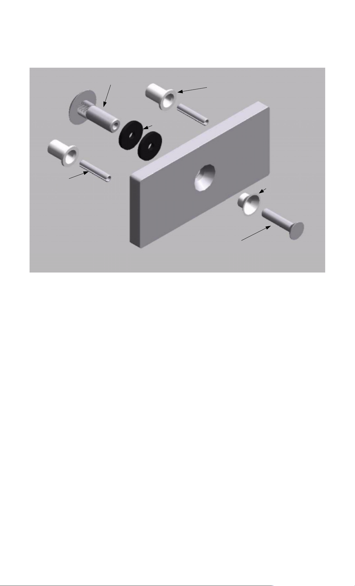
FIG. 3: COLLAPSING THE BLIND NUTS
COLLAPSES WHEN CAP SCREW
DRILL 3/8" (9.5MM) HOLE
PRESS IN BLIND
NUT AS SHOWN
HOLD WITH WRENCH OR
VISE GRIP WHILE TURNING
CAP SCREW
IS TURNED WITH ALLEN WRENCH
WHILE TOOL IS HELD FAST
WITH BOX WRENCH
BLIND NUT
HEADER
KNURL
TOOL
TWO FLAT WASHERS
IF SCREW IS STIFF TO TURN,
ADD LU BRICANT TO WASHERS
WHILE TURNING WITH ALLEN
WRENCH, PRESS IN TO KEEP
NUT SEATED IN HEADER
CAP SCREW
1/4-20 X 1" (US) OR
6MM-1MM X 2 5MM (METRIC)
Step four is to make the necessary wire connections. S t ep five is to mount the magnet via the
supplied machine screws (see Figure 1). Don't forget to use the gold flat washers. They
prevent the narrow screw heads from digging into the resin which could cause damage.
Tighten the screws to a snug fit only. Use the supplied thread-lock on t he screw t hread s t o
avoid th e p ossib il ity of t he s crews l oosen in g over time. Do not drill out the mounting holes
to make f or an easier fit. You may cut an internal wire and void the warranty.
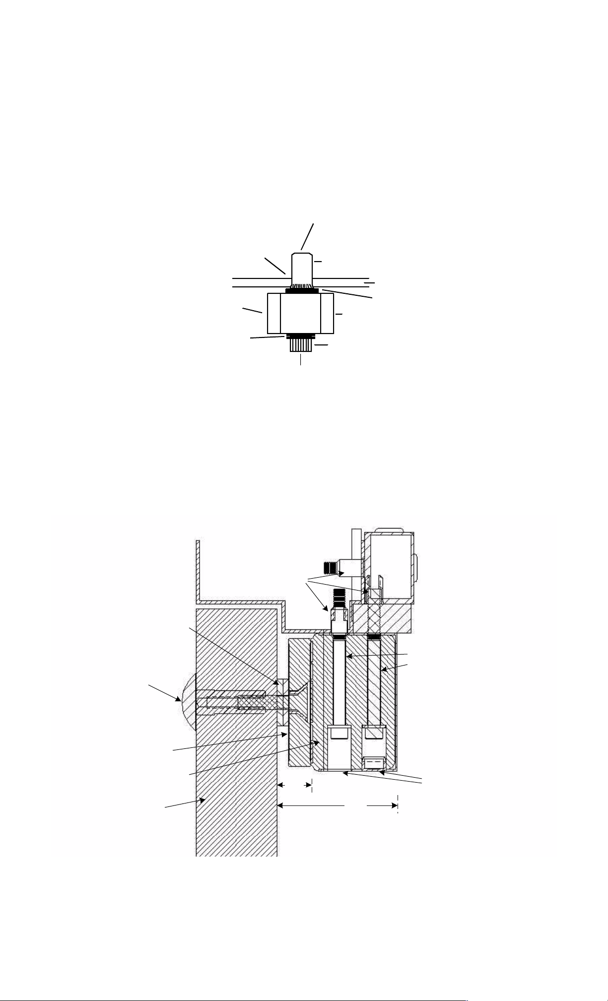
FIG. 4: TYPICAL MOUNTING ON OUTSWINGING DOOR
Header Bracket if
frame is too narrow
Blind Nuts
Stop Filler Plate if
Washer Stack
Stop
stop is too narrow
Sex Bolt
Strike
Magnet Body
Door
.75"
(19mm)
1/4-20 (6mm)
Mounting Screws
Model 62 or 82 is shown
with four magnet mounting
screws. Model 32 or 34
employs only two.
Tamper Caps
(One shown)
2.5"
(63.5mm)
Page 8

Rev. A.3, 5/00 Page- 5
2.4 G ENE RAL INSTALLATI ON ON INS WINGI NG DOOR WITH Z BRACKET
In cas es where th e Mag nalock m ust be mounted on the inswinging side of the door to protect it
from physical assault, the m agnet body is m ount ed fl ush on the wall ab ove the door frame and
a "Z" bracket is affixed to the door which positions the strike in front of the Magnet (part # Z-32,
Z-62 or Z-82 with the su ffix “M” for metric). The model 34 series is not offered in a face
mount version. Securitron's "F" series Magnalocks are used, as they have mounting holes
through the face of the magnet and wire exit to the rear. Figure 5 shows this configuration.
Note that the model 62F has five mounting holes through the face. The “extra” hole is t o
provide flexibility in mounting when the magnet bod y is positioned partly on th e top of the
door frame and partly on the wal l . In that instance, it becomes possible to secure the model 62
mag net b ody with th ree screws wh ich al l g o into t he fr ame head er (man y wal l typ es su ch as
sheet rock do not constitute a secure mounting substrate). Note that when the roll pin
bushings are used, they protrude through the Z bracket and interfere with the Z bracket cover.
If a Senstat lock is being employed, the roll pin bushings must be u sed t o provide in sul ation.
They shoul d be cu t with a hacksaw to fun ction in the bracket. If th e lock is not Senstat, omit
use of the roll pin bushings and drill 3/8" (9.5mm) diameter holes for the roll pins instead of
1/2" (12.7mm). Read sections 2.3, 2.3.1, and 2.3.2 for additional general information on
mounting.
Blind Nut
PN# BN-250 or
PN# BN-6MM (Metric)
(Pack of 24 with tool)
1/4-20 x 2 1/2" Cap Screw
PN# SCS-25 or
6mm-1mm x 60mm
PN# SCS-60mm (Metric)
Pack of four screws
FIG. 5: F M AGNET DIMENSIONS
Model 62F
)
4
2
f
o
r
e
k
h
c
s
a
a
P
(
W
1
-
d
l
o
W
F
G
#
N
P
Tamper Cap
PN# FC-1 (Pack of 24)
If "G" option is furnished, the
wire cable emerges from a 3/4"
male; 1/2" female conduit fitting
on the end of the magnet (62
and 82 models only)
Model 32F
Length Width Depth
32 8" 1.88 1.5
(mm) 203 47.8 38.1
62 8" 2.9 1.75
(mm) 203 73.7 44.5
82 12" 2.9 1.75
(mm) 305 73.7 44.5
Page 9

Rev. A.3, 5/00 Page- 6
FIG. 6: F M AGNALOCK MOUNTING
Architectural Cover slides on
last with open side up and is
attached with supplied double
Roll pin plastic bushing
require 1/2" (12.7mm)
holes and must be
shortened to work in Z
bracket. Roll pin bushings
may be omitted if lock is
not Senstat. Then drill 3/
8" (9.5mm) holes for roll
pins.
Sex Bolt
Drill 1/2" (12.7mm) hole
Strike
Magnet
Header
Z Bracket
Cap Screw:
5/16" x 18, PN# 300-13500 or
8mm-1.25mm, PN# 300-13425 (metric)
stick tape
Z Bracket
T-Nut requires 3/8" (9.5mm) Dia
hole in bracket and accepts
strike mounting screw
Use 1" mounting screw supplied
with Z bracket, PN# 300-13400
or 300-13450 (metric)
Washer Stack
#14 Hex Sheet Metal Screw (2)
PN# 300-13200
Door
2.5 MOUNTING PROCEDURES FOR SPECIFIC DOOR TYPES
2.5. 1 ALUMINUM FRAME GL AS S DOOR MOUNTING
This is a common door type that utilizes the Magnalock. Certain mounting problems can arise
depending on th e configuration of the door and frame. Often, the head er is not wid e enough
for the depth of the magnet. This can mean that none of the mounting screws can be run into
the h eader or that in the case of th e model 62 an d 82, only two of the four will fit. Another
aspect of the mounting screw problem is that the screws might line up with the end of the
head er extru sion. Al so the wir es may exit bey ond t he en d of th e h eader so t hat they will b e
exposed and vulnerable to tampering.
Most of the prob lems are sol ved by the use of Securitron's Universal Header Bracket (part #
UHB-CL or UHB-BK). This bracket will function with the model 32, model 34 or model 62
Magnalock. A separate version (UHB-82) is offered for use with the longer model 82. The UHB
extends t he depth of the header either 1" (25mm) or 1 1/2" (38mm) dependin g on which way
it's oriented. This usually allows mounting of all screws and since the bracket is itself a hollow
extrusion, the wire is run inside the bracket and therefore is hidden. Even with use of the
br acket , it is p ossib l e th at on e set of m oun t ing sc rews may l in e up with th e en d of t h e h ead er
when t he m odel 62 or 82 is us ed. To deal wit h t h is situ at ion, some ad ju st men t of t h e m agn et
mounting position is possible. Instead of the two rubber washers supplied with the strike, one
or th ree may b e used . If th e door is secured onl y by t he Magn alock (th ere is no mechan ical
swingbolt) the door closed position may be altered to allow all mounting screws to be used.
Fin al ly note t hat a mod el 62 ins tal l ation on th is t yp e of d oor is ac cep tab l e if on l y two m oun t ing
screws are used. Since the screws run into steel nuts, the fastening technique is very strong.
It is best to use all four screws, but particularly on this type of door, which is inherently not high
security (the g lass may be shattered for forced entry) firml y mou nting two screws is acceptable.
Aluminum frame headers typically employ a “blade” stop which is far too thin to provide a
mou nt in g su rfac e for t h e mag net . Not e th at Fig u re 4 sh ows t he Mag net mou n tin g on t h e door
stop. Accordingly, on aluminum frame glass doors, the magnet body mounts directly onto the
header. This c an be acc om plished by cutting away a section of the blade stop. This techniq ue
is preferred in th at the p rojection of th e magnet into the opening is minimized. An altern ate
Page 10

Rev. A.3, 5/00 Page- 7
method is to sp ace the mag n et down so as to clear the blade stop . This generally requires 1/2”
of spacing (12.7mm) and Securitron offers brackets of the appropriate width with pre-drilled
cl earan ce h oles for t h e Magn et mou n tin g scr ews. Th ese are t he ASB-32, AS B-62 or ASB-82
(with finish suffix CL or BK). Figu re 6 shows the use of the Al uminu m Shim Bracket (ASB).
Note that this bracket is not offered with the mod el 34. The UMB-34 bracket accomplishes the
same function .
FIG. 7: USE OF THE ASB BRACKET ON ALUM INUM DOOR/F RAME WI TH BLADE ST OP
BLADE
HEADER
DOOR
STOP
ASB BRACKET
MAGNE T
ALUMINUM DOOR AND FRAME
WITH BLADE STOP
O
M
R
O
F
2
3
-
B
S
A
I
W
O
H
S
S
B
S
A
.
N
K
C
O
L
A
N
G
A
M
2
3
L
E
D
6
-
A
H
2
8
/
2
E
V
I
F
S
S
E
L
O
H
STRIKE
SEX BO L T, STRI KE MOUNT IN G SCR EW AND HOLE IN DO O R CAN ALL BE RAI SE D BY
1/4" W HEN OFFSET STRIK E IS U SED WITH MODEL 62 TO SUI T NARROW RAIL
Anoth er pr oblem that can arise wit h al umin um fr ame gl ass doors is that in certain cases with
th e model 62, th e heig ht of the al umin um rail at th e top of th e door is n ot su fficien t to m ount
the strike and sex bolt. Even when the sex bolt is in stalled in the lowest area of the top rail, the
top ed ge of th e st rike wil l p rotr ud e ab ove th e rail . To sol ve th is p rob l em, S ecu ritr on of fers t h e
off set st rike. The holes in t he strike pl ate are offset 1/4" (6.4mm) from the center of the strike
and this allows successful mounting on a narrow top rail. An approximate 10% loss of holding
force results from the skewed position of the strike mounting screw b u t this is not significan t on
aluminum frame glass doors which are not high security barriers. The offset strike is supplied
at n o ad dit ion al c har ge if it' s cal l ed out with t he or der or may be s ent as a rep l acemen t for t he
standard strike. This p r oblem does not occur wit h th e m or e narrow model 32 or 34 so no offset
strike is offered with them.
2.5.2. THE UMB-BRACKET F OR AL UMINUM AND CONCRETE FILLED HE ADE RS
The UMB-34 bracket repl aces t he f u nc tion s of th e ASB b racket (s ee pr evious d rawin g ) an d t h e
CWB bracket (see Section 2.5.5) which permits mounting on wood or concrete filled steel
headers. Th e UMB has th e unique b enefit of being reversible wh ic h al ters the projec tion of the
bracket with respect to the top of the magnet body and allows coping with different stop
thicknesses. The bracket is delivered with a selection of fasteners for different applications.
Wood screws are present for mounting on wood headers; cap screws are present for
ins tall ation in to b lind nu ts an d sh eet metal screws are p resen t for op tional mou ntin g on s teel
headers.
Page 11

Rev. A.3, 5/00 Page- 8
FIG. 8: USE OF THE UMB BRACKET W ITH THE MODEL 34 MAGNALOCK
NOTE HOW BRA CKET CAN BE REVER SED TO COPE WITH DIFFEREN T STOP THICKNESSES
BLADE
HEADER
STOP
HEADER
STOP
UMB BRACKET
DOOR
MAGNET
STRIKE
ALUMINUM DOOR AND FRAME
WITH BLADE STOP
UMB BRACKET
DOOR
MAGNET
STRIKE
AL UMINUM DOOR AND FRAME
WITH BLADE STOP
THE TWO LAR GER HOLES ARE FOR THE
CABLE EXIT. THE TW O THREADED HOLES
ACCEPT THE MAGNET MOUNTING SCREWS.
THE REMAINING FIVE HOLES ACCEPT
DIFFERENT FASTENER TYPES TO MOUNT
TO DIFFERENT HEADERS.
2.5. 3 S OL ID GLASS DOOR MOUNTING
The Magn alock is an excell ent choice for securing 100% gl ass doors with no aluminum rail.
The magnet is suspended in normal fashion from the header and the difficulty in the
installation is mounting the strike plate on the glass door as glass cannot be drilled. This is
accomplished by using Securitron's model GDB (or G DBM with metric fasten ers) Gl ass Door
Bracket and model AKG Adhesive Kit for Glass (see Figure 7). The GDB bracket will work with
either the model 32, model 62, or model 82 Mag nalock (but not with the model 34). The
bracket is affixed to the glass surface by a special adhesive and the strike screws into the
bracket conventionally. The adhesive provides a permanent bond stronger than the holding
forc e of the Mag nalock.
Note t hat we h ave said "100% g lass d oor". Some door s that app ear to b e g lass are ac tual ly
laminated with plastic. I f the M agnal ock wit h g lass door bracket is used on this type of
door, it is possible that failure will occur via delamination.
In som e cases th e head er of a gl ass d oor is vertical glas s. The magn et can b e mou nt ed on
su c h a head er by us ing a 3" X 3" aluminum angl e bracket ( part number HEB- 3G). The bracket
is glued to the vertical glass header with Securitron's adhesive kit for glass and the magnet is
screwed to the bracket.
Page 12

Rev. A.3, 5/00 Page- 9
FIG. 9: STRIKE INSTALLATION ON 100% GLASS DOOR
S
S
A
L
G
A
L
G
ADHESIVE
BOND
2 X RUBBER
WASHERS
R
O
O
D
B
R
O
O
D
S
S
T
E
K
C
A
R
E
K
I
R
T
S
1/4" X 3/ 4"
ROLL PINS
NOTE: OMIT ROLL PIN WHITE PLASTIC BUSHINGS
5/16-18 x 1" (US) O R
8MM - 1.25MM X 25MM
(METR IC)
FLATHEAD SCREW
WHITE PLASTIC
BUSHING
2.5. 4 DOUBL E DOOR MOUNTING
Several p oss ibil it ies exist f or th is ap p l ication . In som e cases, on e of th e door l eaves is pi nn ed
so that onl y one leaf is used and this is secu red b y a sing le Magn alock . If bot h l eaves are to
be active, two Magnalocks can be used. For the most attractive installation, they should be
butted together but if obstructions exist in th e header that interfere with mounting, the magnets
can be separated somewhat. Another possibility is to use Securitron's split strike which is
available for the model 62 and model 82 (use of a split strike with the model 32 or 34 series
would provide inadequate security) In this method, a single Magnalock is mounted in the
cen ter of th e h ead er an d a h al f s ize st rike is m oun t ed on each leaf . This r ed uc es th e hol d in g
forc e t o abou t 550 l bs. (250 KG) for each leaf with t he mod el 62 and abou t 850 lb s. ( 385 KG)
for eac h leaf with the model 82. The s plit s trike (p ar t num ber ASS-62 or ASS-82 with “M” suffix
for metric) is available either as part of a complete Magnalock or supplied separately as a
rep lacemen t for t he st andar d str ike. Read s ection 2. 7 for in formation on Dress Covers wh ich
improve the appearance of a d ouble door install ation. Certain electronic consideration s also
appl y wh en Magnal ocks are used on double doors. See section 3.5.4.
2.5. 5 STEEL HEADE R FILL E D WITH CONCRET E OR W OOD FRAME MOUNTING
Securitron offers a combined bracket in three versions to suit the three Magnalock families.
The part number of the “Concrete/Wood Bracket” is CWB-32, CWB-62 or CWB-82. Two
finishes are available (suff ix CL or BK) and for metric locks, the b rackets inclu de th e suffix “M”.
Note that the CWB bracket is not offered with the mod el 34. It’s fun ctions are accomplished by
the UMB bracket for the model 34.
In concrete filled headers, the blind nuts function normally but a problem can occur in pulling
the hook up wires as it is difficult to run a wireway in con crete. The center of th e bracket for the
model 62 and model 82 versions forms a splice chamber if it's difficult to pull the wires back
int o th e h eader . Th e mod el 32 version h as a s lot to b rin g th e wire in to t he h ead er bec aus e of
the narrowness of the lock. Alternately the wires may be pulled through the edge of the
bracket by drilling a hole if it's impractical to drill the concrete. A final technique for concrete
headers is the use of Secur itron' s "G" version Magn alock (n ot available in the 32 or 34 series)
which incorporates a 1/2" female/-3/4" male universal threaded conduit fitting. The conduit
fitting is placed on the end of the magnet body, and the problem of pulling wires into concrete
is bypassed as the wires may be run in pipe in a surface mount configuration. The mounting
holes on " G " locks are counter-bored from both sides to make the lock non-handed.
With a wooden frame, lon g wood screws are used to mou n t t h e Magn aloc k. Th e scr ews mu st
penetrate as deeply as possible through the stop and frame into the header to yield adequate
mounting strength. The Magnalock mounts to the bracket via machine screws and the bracket
per m its wood sc r ews ( furn i s hed) t o penet r ate deep ly into the header (s ee Figu r e 10)
Page 13

Rev. A.3, 5/00 Page- 10
FIG. 10: WOOD FRAME AND CONCRET E HE ADE R BRACKE T
CWB-32
R
E
B
M
A
H
C
E
C
I
L
P
S
1/2"
WO OD SCRE WS U SED
FO R WOOD FRAME
MAGNET SCREWS INTO
2 OUTSIDE TAPPED HOLES
SHEET METAL
SCREWS
FOR CONCRETE
HEADER
USED
USE ALL FURNISHED SCREWS FOR
PROPER MOUNTING SECURITY
CWB-62 AND CWB-82
R
E
B
M
A
H
C
E
C
I
L
P
S
1/2"
WOOD SCREWS USED
FOR WOOD FRAM E
SHEET METAL SCREWS
USED FOR CONCRETE
MAGNET SCREWS INTO
4 OUTSIDE TAPPED HOLES
HEADER
2.6 MOUNTING THE MAGNALOCK ON EXTERIOR GATES
A popular application for the Magnalock is to secure motorized or manual exterior gates. The
Magnalock has several benefits in this application. Gates tend not to be precisely fitted so
electric bolts suffer from alignment failures. The Magnalock is designed to be self aligning and
tolerates considerable inconsistency in the gate closed position as regards upward/downward
alignment, side alignment and twisting. The Magnalock is al s o fully seal ed and waterp r oof so it
is generally unaffected by tough environments.
The drawings and descriptions which follow, show conceptual installation concepts for different
typ es of g ate sec ur ity ap p l ication s. Note t h at t h e mod el 62 an d mod el 82 are most common l y
used in gate installations. They have conduit fittings available (“G” option) while this is not
available on the model 32 or 34 Most g ate installations also call for higher levels of holding
forc e as gat es are often lar ge and poorl y fit tin g . It ’s al so oft en th e case t h at an in tru d er is ab l e
to physically apply more force to defeat a gate lock than is the case with (especially) an
outswing ing door wherein th e intru der can only pull on it. The model 32 or 34 h owever may be
us ed on certain g ates wit h su ccess. A g ood exampl e is a slid ing gate wh ere th e Magnet can
be mortised into a post against wh ich the gate sl ides. Securitron also offers the model 34R
Magnalock which is specifically designed for mortising (see catalog).
Becau se of th e wide variety of gates in existence, each in s tall ation h as to be considered special
and normally, bracketry must be made up on site. The concept is to mount the magnet on a
fixed post and the strike plate to the swinging or sliding member of the gate. Position both
components so that the strike p late slaps against the magnet face on cl osure. Usuall y, the
"GF" version of the Magnalock is used for gates. "G" calls out a conduit fitting mounted on the
magnet end and "F" calls out mounting holes through the face (see Figure 5). The magnet
typically screws onto a b ac k plat e fashioned on s ite and the b ac k plat e is welded onto the f ixed
post.
Page 14

Rev. A.3, 5/00 Page- 11
A back p l ate or Secu rit ron 's Z b rack et mu st al so ty pic all y b e p rovid ed f or t he s trik e pl at e. The
strike plate cannot be directly welded to the gate as it will not be able to flex and self
align. It must be screwed onto a surface with the washer stack used to provide
flexibility. Note th at if Securitron 's Z bracket is used, it typically bolts to the gate rather than is
welded as it is aluminum. Read sections 2. 3, 2.3.1, and 2. 3.2 for ad dition al general inf or m ation
on mounting.
FIG. 11: MOUNTING TECHNIQUES FOR GAT E S
SINGLE SWING G ATE
CONDUI T FI TTING MAY EXIT TOP OR BOT TOM
GF MAGNET
Z BRACKET BO LT ED TO SWIN G AR M
STRIKE
INTERFERENCE PIECE MUST
BE ADDED TO Z BRACKET
CONDUIT FITTING
DOUBLE SWING GATE
Z BRACKET BOLTED TO SWING ARM
DIRECTION OF OPE NING
SLIDING GA TE
GATE
EDGES
MOT ORIZED OPENING MU ST BE
COORDINA TED
EXTENDED ROLL PIN
ANGLE BRACKET
GF MA GNET
LOCK NUTS
ANG L E BRACKE T
SPRING
EXTENDED ROLL PIN
STRIKE
Page 15

Rev. A.3, 5/00 Page- 12
In th e case of very tal l an d l arg e g ates , a l evering p rob l em can exist. By t h is we mean th at an
intruder may be able to flex the gate enough to take up the slack in the strike mounting screw
and th en lever off the st rike pl ate. If the in stal ler or u ser d etermin es that this may hap pen , a
single Magnalock will not provide adequate security and two must be used, typically at the top
and bottom of the gate.
Figure 11 (above) shows preferred special techniques for Magnalock mounting on 3 types of
gat es. The f irst d rawing shows a
single swinging gate. The general technique follows the
principles discussed above but the use of Securitron's Z bracket which creates a neat
installation is also shown. Note that in some cases, the post which mounts the magnet is
hollow. It is possible to use the "F" version (without conduit fitting) and pull the wires through
the post which m ay y ield a neater an d more secure install ation.
The second drawing shows a
double swinging gate which presents a unique problem. The
Magnalock is mounted in the same general way as on a single swinging gate but since both
arms move, an intruder pushing on the gate exerts a shearing force on the Magnalock.
Electromagnets are not at all strong in this orientation of attack. Therefore, as the drawing
shows, Securitron's Z bracket should be used with an interference piece which blocks the
shearing effect while the strength of the magnet blocks one arm moving while the other is
stationary. For this technique to work, the motorized operator must be
coordinated which
mean s th at one ar m mu st move first to c l ear th e in ter feren ce p iece b ef ore th e oth er arm s tart s
moving. Gate operators c an norm ally ac c om plish th is .
The final drawing on Figure 11 shows a special mounting technique for
sliding gates. We
recommend the use of the "GF" type magnet and two 3" angle brackets (available from
Secu rit ron ) for a neat instal l ation . A spec ial s trik e mou nt in g t ech n iq ue is s hown in th e d rawin g
which imp roves reliability. The probl em is that if the strike is mounted normally to th e angle
bracket and the gate is a powerful one which slams shut, the magnet may be impacted to the
point where its mounting screws loosen or the bracket bends. The strike mounting technique
th at is sh own c reates a "sh oc k ab sorb er" eff ect by th e u se of l ock nu t s at t h e rear of th e st rike
and the rear of the bracket together with a spring. A through hole (rather than tapped) is
drilled in the angle bracket mounting the strike and extra long roll pins are used. When the
gate closes, the s trike moves in against the spring which is the shock absorb ing action.
2.7 USE OF DRESS COVERS
Once th e physical in stall ation is complete, you may want t o consider the use of a dress cover.
Dress covers are metal stampings which slip over the magnet body and are affixed with
permanent double stick tape (supplied). The dress cover accomplishes three functions: First,
it makes for a more attracti ve in stall ati on by concealing the strike plate and mounting holes.
All that is seen is an attractive rectangular form on the door. Second, the cover provides an
extra degree of tamper proofing and finally it allows easy alteration of the finish for
architectural com patib ility. Dr es s c overs ar e avail able in clear aluminum, s atin black aluminu m ,
polished st ainless and polish ed brass finishes.
Double d r es s c overs ar e also availab le for in s tall ations on dou ble doors. In th is case, th e cover
fits over two locks so long as they are not separated by more than 2" (50mm). Doub le dress
covers h ave all th e ad vantag es m ent ion ed ab ove and in ad dit ion pr od uc e th e app earan ce of a
single device which inside is really two. Consult the catalog for dress cover part numbers.
2.8 TAMPER PROOFING THE MAGNALOCK
In situ ation s wher e vand al ism is expect ed, th e Magn al ock sh oul d b e pr otect ed from tamp erin g .
The magnet itself is inherently tamper-proof being totally sealed. The magnet mounting screws
are vulnerable in that the magnet can be dismounted if the screws are loosened. The all en
holes on the screws can be filled with a potting compound, such as Devcon, or silicone.
Alternatel y, the entire hole in the mag net wh ere the screw heads fit could be filled. Butyrate
caps are supplied to close the mounting holes. These provide some tamper proofing as they
can't be removed by hand, but can be pried out with a tool. Regarding the strike plate
mounting screw, it is covered by the strike when the magnet is energized. If tampering is
anticipated when the door is op en, the screw socket head may be fill ed.
Another possibility is that
Securitron inventories special tamper proof screws for both
magnet and strike mounting. These screws are identical allen head types except that it
requires a special key to install and remove the screws. It is unlikely that a vandal would have
access to this type of key. Securitron optionally supplies the tamper proof screw sets with keys
both in the form of a man u al allen wrench and in a bit key usable with a drill.
Page 16

Rev. A.3, 5/00 Page- 13
3. ELECTRICAL INSTALLAT ION
3.1 GE NE RAL ELECT RICAL CHARACTERISTICS
The Magnalock constitutes a low current electric load. Owing to internal circuitry, the
Magnalock does not show the normal characteristics of an electromagnetic or other inductive
load. Inductive kickback is suppressed, so arcing across switch contacts need not be a
concern. This suppression also protects nearby access control or computer equipment from
possible interference. The circuitry performs the additional functions of canceling residual
magnetism ("stickiness" on release) and accelerating field collapse so that the Magnalock
rel eas es nearly instantly when power is removed. El ec trically s peaking, the load is nearly pu r e
resistive in nature although there is a modest capacitive component which depends on the
series. The fol l owin g c har t sh ows t h e cu rren t dr aw for eac h version an d th e d egr ee of in ter nal
capacitance.
32 @ 12V 32 @ 24V 34 @ 12V 34 @ 24V 62 @ 12V 62 @ 24V 82 @ 12V 82 @ 24V
CURRENT 300 mA 150 mA 350 mA 175 mA 250 mA 125 mA 350 mA 175 mA
CAPACITANCE 0 0 0 0 30 M fd 15 Mfd 30 Mfd 15 Mfd
Capacitance can be an issue if very sensitive switch contacts are used to control the Magnalock
(such as a low cu rrent reed switch). A capacitive load incl ud es some inrush cu rrent wh ich can
stress these contacts. Note however that the probl em is dimin ished wh en the Magnalock is
mounted some distance from the control switch as the interconnecting wiring adds a series
resistance to the circuit which sharply limits th e inrush.
3.2 STANDARD LOCK
For operation, DC voltage must be provided to the lock. The red wire receives +12VDC or
+24VDC, an d the black wir e, 0V (negative). If the l ock i s con nect ed w it h reverse p ol arity, it
will not function at all. The voltage source may be regulated, filtered or pulsating DC
(transformer + bridge rectifier). Half wave pulsating DC generated by a transformer and
single diode will not properly operate the Magnalock. An exact voltage level is not
nec essary . Less than st an dar d vol tag e wil l p rop or tion atel y r edu ce h ol d ing f orce b u t wil l cau se
no harm. O vervol tage up to 30% is acc eptab le.
The model 34, 62 and 82 series Magnal ocks are
du al vo ltag e un it s. Th is mean s t hat you can
apply either 12 or 24 volts to the same unit and it will operate equally well. Dual voltage
Magn alocks are auto-switching which means that you still apply power to the red and black
wires, while observing correct pol arity. The lock, however, aut omati call y det ects wh eth er it is
receiving 12 or 24 volts and d raws t h e correc t amou n t of cu rr ent for th at vol tag e (t he c ur ren t is
twice as hig h when th e lock is r eceiving 12 volt s th an wh en it is rec eiving 24 volts ). Th e mod el
32 series has sep ar ate models for 12 an d 24 volt operation .
It is good practice to use power supplies with 1/3 extra capacity beyond the current
requirements of the load. This greatly reduces the possibility of heat induced power supply
failure and also allows for future expansion. Power supply cost is a small fraction of the job
cost and sh ou ld not b e skimped on.
Switches may be wired as necessary between the Magnalock and power source. Internal
circuitry eliminates inductive kickback, so neither electromechanical switches nor solid state
devices will be damaged by arcing when the Magnalock is shut off.
3.3 AVOIDING POOR RELEAS E CHARACTERIST ICS
One of the exceptional features of Magnalocks is near instantaneous release. This is
par ticul arly valu abl e when t he l ock is bein g swit ched off an d th e door is being open ed at t he
same time as occurs when a switched exit device l ike Securitron ’s Touch Sen se Bar is b eing
us ed. Two separate wirin g errors can however cau se Magn alocks t o release s lowly (in on e or
two seconds) and this is annoying.
The first probl em is
con nectio n of a reverse d iode i n paral lel w ith th e lock' s power i nput.
This is often done to suppress inductive kickback from a coil such as a relay coil or solenoid.
Magnal ocks already have internal inductive kickback protection, so addition of a reverse diode
is pointless. The diode does act to "recirculate" current flow through the magnet coil and
th ereby c onsid erabl y slows r elease. A d iode sh ould never be c onnec ted as sh own in Figu re
12.
Page 17

Rev. A.3, 5/00 Page- 14
The second problem is when any load is operated in parallel with the Magnalock. A good
example would be adding an incandescent lamp in parallel with the lock so that the lamp
would be illuminated when the lock is powered. The lamp acts like a resistor and allows
current recirculation which will greatly slow lock release time. When you want to add a resistive
load in parallel with the lock, you must put a fo rward diode in series with t he resist ive load.
This wil l b lock r ecircul ation and r estore q uick rel ease. Corr ect pr actice is s hown in Fig ure 12
below.
A special case exists when you use an
LED connected in parallel with the Magnalock (to
sh ow th at t h e Magn aloc k is on for exampl e). This d oes n ot sl ow r el ease as th e LED does n ot
all ow rec ircu l ation b ut th e l imit ed r ecirc ul at ion en erg y wil l event ual l y b u rn ou t t h e LE D. LED’s
are susc eptib le to even a tiny amou nt of reverse volt age. Th erefore ad d th e forward diod e as
you would with an incandescent lamp (see Figure 12) to extend the life of the LED.
FIG. 12: WIRING CONSIDERATIONS TO AVOID SLOW RELEASE
RED
RED
MAGNALOCK
BLACK
NEVER CONNECT PARALLEL
REVERSE DIODE AS SHOWN
BLACK
USE A FORWARD DIODE WITH ANY PARALLEL
RESISTIVE LOAD SUCH AS A LAMP
MAGNALOCK
3.4 W IRE GAUGE S IZING
If the power supply is distant from the lock, voltage will be lost (dropped) in the connecting
wires so that the Magnalock will not receive full voltage. The following chart shows the
minimum wire gauge that will hold voltage drop to an acceptable 5% for different lock to
power supply distances. Proper use of the chart assumes a dedicated pair of wires to
power each Magnal ock (n o common n eg ative). Not e th at a Magn al ock op erat ing on 24 volt s is
a much bett er choic e for long wire run s as it has 4 times th e res istan ce of a 12 volt ins tal l ation .
Also not e t hat th e correct calcu lation of wire siz ing is a very imp ortan t issu e as th e instal ler is
responsible to insure that adequate voltage is supplied to any load. In multiple device
installations, the calculation can become quite complex so
refer to Appendix B for a more
comp lete discussion.
Distance Gau ge 12V Gau ge 24V Dist ance Gau ge 12V Gauge 24V
80 FT 20 GA 24 GA 800 FT 10 GA 16 GA
200 FT 17 GA 22 GA 1500 FT. 8 GA 14 GA
400 FT 14 GA 20 GA 3000 FT N/A 12 GA
3.5 SENS TAT M AGNALOCKS: “SC”
Securitron's optional patented Senstat feature provides true lock status sensing. In many
electrically controlled door security systems, status sensing is provided by a magnetic switch
on th e d oor itsel f. This ind icates t he door is closed bu t not necess arily sec ured . Secu ritron 's
Sens tat monit ors th e loc k rat her th an th e d oor an d th eref ore p rovides h ig h er secu rit y ( bu t not e
that it can’t be used as an auto-relock input to an access control system).
An “SC” Mag nalock provides a dry SPDT ou tpu t which c hanges stat e when t he lock is reporting
secure
(1 Amp @ 30 V DC maximum) . This is accomplished by conducting the input power of
the lock through the strike and employing it to energize an internal SPDT relay. The white wire
is th e Sen st at r elay common . Green is c los ed t o wh ite wh en th e l ock is s ecu re an d O ran g e is
cl os ed to white when the l oc k is not secure.
Page 18

Rev. A.3, 5/00 Page- 15
FIG. 13: “SC” SENSTAT WIRING
BLK
POWER
SUPPLY
+
WHITE AND GREEN WIRES PROVIDE ISOLATED CLOSURE WHEN LOCK IS SECURE.
ORAN GE AND WHITE ARE CLOSED WHEN LOCK IS NOT SECURE (AS SHO WN ABOVE).
"SC" LOCK
RED
ORANGE
GREEN
WHITE
3.6 DOUBLE DOOR PROCEDURE FOR STATUS RE P ORT ING
Often two Magn alocks are mount ed on a doubl e door and are tu rned on and off together (no
separate control). As to status reporting, it is of course possible to receive a separate Senstat
status signal from each door or you can co mbi ne th e ou tp ut s so that if both locks are secure,
the double door is secure and if either lock is not secure, the double door is not secure.
Simply tie the two wh ite wires t ogether from th e two locks. A circuit will be cl osed between the
two green wires only when b oth locks are reporting secure. If either is not secure, t he circuit
between the two gr een wires wil l be open. The orang e wir es are not used. See Fig ure 14.
FIG. 14: DOUBLE DOOR WIRING WITH "SC" LOCKS
GREEN
GREEN
"SC" LOCKS ARE INTERWIRED AS SHOWN TO P ROVIDE STA TUS MONITORING. AN IS OLATED CLOSU RE
WILL EXIST BETWEEN THE GREEN WIRES ONLY IF BOTH LOCKS ARE SECURE.
"S C" L OCK
"S C" L OCK
WHITE
WHITE
3.7 DOUBLE DOOR CONTROL S WITCHING
It’s common t o control two locks from a sing le access and/or exit switch on doub le doors or on
an install ation where two locks are mounted on a single door. In nearly al l cases, th is works
with n o problem but occasional ly the release can appear to be “sticky” for simil ar reasons to
those discussed in Section 3.3 This h appens when one of the locks is poorly coupled to its
str ike pl ate. This cou ld occu r becaus e of an in stal lation prob lem ( the st rike pl ate is n ot bein g
allowed to swivel) or because of some obstruction between the plate and magnet surface.
When an electromagnet is n ot well coupled to its strike plate, its magnetic fiel d coll apses so
rapidly that it provides some energy to recirculate in the second magnetic lock, slowing the
rel eas e of that lock.
FIG. 14: DOUBLE POLE SWITCHING OF TWO LOCK INSTALLATION
TWO POLE
POWER
SUPPLY
+
SWITCH
RED
MAGNAL OCK #1
RED
MAGNAL OCK #2
BLK
BLK
Page 19

Rev. A.3, 5/00 Page- 16
So if you notice sl ow release on a doub le lock instal lation, this is telling you that one of the
locks is not holding properly and that the problem should be corrected. Alternately, any
ch ance of slow release c an be eliminat ed by c ontrol ling the two locks with a doub le pole s witch
or relay. This blocks th e recircul ation path and is shown in F ig ure 15.
3.8 EMERGENCY REL E AS E
Magnal ocks are often wired into a system such that they can b e released in an emergen cy -either manually from one switch or automatically, often from the fire alarm system. It is the
user's responsibility to accomplish this hookup correctly according to these instructions and
good el ect rical p ract ices. In g en eral , we rec ommen d th at a switc h or rel ay b e us ed t o p erfor m
a series break of all DC power which is the simp le and sure way to make sure the d oors do
release. Securitron power supplies have terminals for interconnection of such emergency
release switches. Finally please note that
it is the responsibility of the end user and
deal er/inst aller to insu re t hat Magn alock i nstall ation s compl y with any appl icabl e fire or
building codes.
MAGNACARE LI MITED LIFETIME WARRANTY
SECURITRON MAGNALOCK CO RPORATI ON warr ants t hat it w ill replac e at cust omer’s r equest, at any t ime for
any reason, products manufact ured and branded by SECURITRON.
SECURITRON will use its best efforts to ship a replacement product by next day air freight at no cost to the
customer within 24 hour s of SECURITRON’s receipt of the product from customer. I f t he cus tomer has an account
with SECURITRON or a valid credit card, the customer may order an advance replacement product, whereby
SECURITRON will char ge the customer’s a c c o unt fo r the pric e o f the pro duct plus next day air fre ight , and will credit
back to t he cust omer the full amount of the charge, including outbound fr eight, upon SECURI TRON’s r eceipt of the
original product from the customer.
SECURITRON’s sole and exclusive liability, and customer’s sole remedy, is limited to the replacement of the
SECURITRON product when delivered to SECURITRON’s facility (freight and insurance charges prepaid by
customer). The replacement, at SECURITRON’s sole option, may be t he identical item or a newer unit which ser ves
as a functional r eplacement. In the event that the product type has become obsolete in SECURITRO N’s product
line, this M AGNACARE warranty will not apply. This MAGNACARE warr anty also does not apply to custom, built to
order, or non-catalog items, items made by others (such as batteries), returns for payment, distributor stock
reductions, returns seeking replacement wit h anyt hing ot her than the ident ical pr oduct, or products installed outside
of the United St ates or Canada. This MAGNACARE warranty also does not apply to removal or installation c ost s .
SECURITRON will not be liable to the purchaser, the customer or anyone else for incidental or consequential
damages arising from any defect in, or malfunction of, its products. SECURITRON does not assume any
res po nsibility for damage or injury to per son or property due to improper care, st orage, handling, abuse, misuse, or
an act of God.
EXCEPT AS STATED ABOVE, SECURI TRON MAKES NO WARRANTIES, EITHER EXPRESS O R IM PLIED, AS
TO ANY MATTER WHATSOEVER, INCLUDING WITHOUT LIMITATION THE CONDITION OF ITS PRODUCTS,
THEIR MERCHANTABILITY OR FITNESS FOR ANY PARTICULAR PURPOSE.
PATENTS
Securitron’s Magnalock is covered under U.S. patents #4,516,114 and 4,682,801.
Page 20

Rev. A.3, 5/00 Page- i
APPEND IX A
TROUBLESHOOTING
PROBLEM-- No magnetic attr act ion bet ween magnet and strike plate.
First be sure the lock is being correct ly powered wit h DC voltage. This includes connect ing t he pow er wires w ith
correct polarity. Positive must go to red and negative to black. If t he Magnalock is wired in reverse polarity, it w ill
not be damaged, but it w ill not oper ate. I f t he unit continues t o appear dead, it must be electrically checked with an
Ammeter. It must be powered with the correct input voltage and checked to see if it dr aw s the specified current. If
the unit meters correct ly, it is putting out the correct magnetic field and the pr oblem must lie in the mounting of t he
strike ( see next paragraph). Sect ion 3.1 includes a c hart showing current draw for all Magnalock versions.
PROBLEM-- Reduced holding force.
This problem usually expresses itself in terms of being able to kick the door open or to open it with a shoulder.
Check the st rike and magnet face t o see if some small obstruction is interfering with a flat fit . Even a small air gap
can grea tly reduce the holding force. Another p os s ib ility is if the strik e plate has a dent on it f rom being dropped for
example. Remove the strike from the door and try to rock it on the magnet f ace to insure it is flat. I f the str ike and
magnet are flat and clean, t he cause is near ly alway s impr oper mounting of the strike in that the strike is mount ed
too rigidly. The strike
mounting screw. The magnet then pulls it into flat alignment. To correct the problem, try loosening the strike
mounting sc rew to see if t he lock then holds properly. Another possibility is if you are operating the lock on AC
instead of DC or on half wave rectif ied DC (tr ansfor mer + single diode). Half wave rectified DC is unacceptable; you
must, at a minimum employ full wave rectified DC (transformer + br idge) .
must be allowed to float around the r ubber washer stack w hich must be on the strike center
PROBLEM-- The Senstat output does not r epor t secur e.
Because of the simplicity of Securitron's patented Senstat design, this is almost always a c ase of the lock st atus
sensor doing its job. It is not reporting secure because a small obstruction or too stiff ly mounted strike is causing the
Magnalock to hold at reduced f orce. The problem is correct ed by cleaning t he surfaces of the magnet and strike or
establishing pr oper play in the strike mount ing. If this doesn't work, you can verify function of the Senstat feature as
follows. Note t hat there are 2 t hin vertical lines on t he magnet face t hat can be said to s eparate t he core int o 3
sections from left t o right. The Senstat output is created by the str ike establishing electrical contact bet ween the
leftmost and rightmost core segments. With the lock powered, use a pair of scissors and press the points
respectively into the leftmost and rightmost core segments. The Senstat output should then report secure. This
shows that the problem lies in the strike not making correct flat contact with the magnet face. If the scissors
technique doesn't cause the lock to report secure, check to see if t here is a broken Senst at w ire. If t his is not the
case, t he lock must be ret urned to the fact or y for replacement.
PROBLEM-- The lock does not release.
When power is removed from it, the Magnalock must release. If internal circuitry, which eliminates residual
magnetism, wer e to fail completely, t he lock would only exhibit "s tickiness" at a rough level of 5 pounds. Therefore
the compla int of " lock w ill not r elea se" is either mechanical bonding via vandalism or a f ailure to c omplet ely re lease
power. By mechanical bonding, we simply mean that glue has been applied between the strike and magnet as a
prank. Failure to completely release power is generally a wiring integrity problem. What happens is that an
upstream switch removes power fr om the wires going to the Magnalock, but through an installation er ror, t he wires
have their insulation abraded between the switch and lock so that partial or full power can leak in from another
Magnalock or other DC device with similarly abraded wiring. This is most likely to occur at the point where the wire
cable leaves the lock case and ent ers t he door frame. Another area is via an improper splice on w iring in conduit .
Either a metal door frame or t he metal conduit is capable of leaking power bet ween multiple devices with abr aded
wires, thereby bypassing switches. A good way to check this electrically (as opposed to visually removing and
inspecting the wires) is t o use a meter and check for leakage between the power supply posit ive or negative and the
door fr ame and conduit. M agnalocks should be power ed by isolated DC voltage wit hout any eart h gr ound refer ence
to positive or negative. Not e that tw o types of wir ing errors can cause
you are making either of these error s.
slow release. Review Section 3.3 to see if
PROBLEM-- The lock rusts
Both the Magnalock core and strik e plate ar e plate d and sealed f ollowing a militar y specif icatio n. Because of this
plating and t he sealed nat ure of the magnet, t he Magnalock is weatherproof and may be used outdoors. I f rusting
appears, the mos t common cause is t hat improper cleaning (with steel wool for instance) has occurred and this has
stripped off t he relatively soft plating. Once the plating has been removed, it cannot be restored in the field, so the
lock will have to b e pe riodically c le aned and co a ted wit h oil or other r ust inhibitor . A rusty Magnalock w ill s till function
but at reduced holding force. If the product is installed in a heavily c or r os ive at mosphere, s uch as near the ocean, it
will eventually rust even with no n abras ive cleaning. The only answ er then becomes continued per iodic removal of
the rust.
Page 21

Rev. A.3, 5/00 Page- ii
PROBLEM-- Apparent electronic noise interfer ence with t he access contr ol system.
Electric locks, being induct ive devices, return voltage spikes on their power wir es and also emit microwave radiation
when switched. This can int erfere w ith access contr ol electronics causing malfunctions. Access cont rol contractors
often employ installation techniques designed to isolate the access control electronics from the electric lock. These
include separate circuits for the lock, shielded wiring and other techniques. These techniques will vary with the
sensitivity of the access control system electronics and should, of course, be followed. Note that Magnalocks
include internal elect r onics which suppres s both inductive kickback and radiation. They have been extensively tested
and accept ed by numerous acces s cont rol manufact ur ers and have been used in t housands of installations without
incident. An apparent noise problem is therefore usually not caused by the Magnalock. The access control
equipment may be itself f aulty or have been installed improperly. One problem can ar ise with the M agnalock. If the
Senstat version is being used, the strike plate (which passes cur rent) must be isolated from a metal door and frame.
Securitron supplies insulating har dwar e to accomplish this but the har dware might not have been used or the str ike
may be scraping against the header for instance. Check for full isolation between the strike and the door frame
(when the door is secure) w it h an Ohmmeter. The presence of lock voltage pot ential in the door fr ame can interf ere
with the ground ref erence of access control system data communication and therefore cause a problem.
IF YOUR PROBLE M PERS ISTS
CALL SECURIT RON T OLL FREE
1-800-MAG-LOCK
APPEND IX B
CALCULATING WI RE GAUGE SIZING
The gener al practice of wire sizing in a DC circ uit is to avoid causing voltage dr ops in connecting w ir es which reduce
the voltage available to operate the device. As Magnalocks are very low power devices, they can be oper ated long
distances from their power source.
calculate the correct gauge of wire to avoid excessive voltage drops.
This is done by adding t he r esistance of the Magnalock to the resistance in the power w ires and then dividing the
wire r esistance by the total resist ance. This yields the fraction of voltage drop in the wires. For example, a single
model 62 Magnalock has a resistance of 192 ohms when being operated on 24 volts. If t he wires completing the
circuit between the Magnalock and it s power source have a resistance of 10 ohms, the total r esistanc e is 202 O hms.
Dividing 10 Ohms (the wire resistance) by 202 (the total resistance) yields roughly 1/20 or 5% . If the input voltage is
24 volts, 5% of t his voltage will be dropped in the wires (1.2 volts) leaving 22.8 volts to oper at e the Magnalock. This
will ca use a s mall reduction in holding force but in general, will be ac c e ptable.
To calculate the wire resistance, you need to know the distance from the power supply to the Magnalock and the
gauge (thickness) of the wire. The following chart shows w ir e r esist ance per 1000 f t (305 meters):
Wire Gauge Resistance/1,000 ft Wire Gauge Resistance/1,000 ft
8 Gauge .6 Ohms 16 Gauge 4.1 Ohms
10 Gauge 1.0 Ohms 18 Gauge 6.4 Ohms
12 Gauge 1.6 Ohms 20 Gauge 10.1 Ohms
14 Gauge 2.5 Ohms 22 Gauge 16.0 Ohms
For any job that includes long wire runs, the installer must be able to
Model 32 resistances are 160 O hms for t he 24 VDC version and 40 Ohms for t he 12 VDC version.
Model 34 resistances are 136 O hms for 24 VDC operat ion and 34 Ohms for 12 VDC operat ion.
Model 62 resistances are 192 O hms for 24 VDC operat ion and 48 Ohms for 12 VDC operat ion.
Model 82 resistances are 136 O hms for 24 VDC operat ion and 34 Ohms for 12 VDC operat ion.
Let's look at some other sample calculations. Suppose a single 62 Magnalock operat ing on 24 volts is 1200 ft from
its power supply and w e're using 20 gauge w ire. Firs t, t he total length of the pow er wires is 2400 ft.
that you combine the wire lengths from the power supply to t he lock and back to the power supply to get
the total circuit wire length. The wire r esist ance than becomes 2.4 X 10.1 O hms which is 24. 2 Ohms. Adding this
to the Model 62 Magnalock resistance of 192 Ohms (at 24 volts) yields a t otal res istance of 216.2 Ohms . 24.2
divided by 216. 2 y ields the percent drop in the wires w hich is over 11% which w e would consider excessive. The
problem can be dealt with in 2 ways. You can utilize 16 gauge wire which would reduce the drop to a more
acceptable 5% range or y ou can provide extra voltage at t he pow er supply. For instance, Securitron 24 V power
supplies are adjustable from 24 to 28 volts. You can therefore easily set the power supply to output 11%
overvoltage which will then deliver 24 volt s at t he lock. The Magnaloc k will a ccep t up t o 30% overvoltage w ithout ill
effects.
Remember
Page 22

Rev. A.3, 5/00 Page- iii
Note that a Magnalock operat ing on 12 volts has 1/4th the resistance of a unit operating on 24 VDC. This means
that wire voltage drops are 4 t imes more significant in a 12 volt system t han in a 24 volt system.
has wire runs long enough to be of concern, always use 24 volts. Note also that it's common to mount 2
Magnalocks on a double door and operate them as one lock (only 2 power w ires) . In this case, the resistance of t he
pair of locks is half t he resistance of a single lock.
In mult iple lock jobs with a single pow er supply, the calculation of wiring voltage drops is more diff icult. So long as
you run a separate pair of pow er wires to each lock, t he calculation is as simple as has been described above, but if
a common power wire is used in a loop str ucture, t he locks powered by the single loop will have an increas ingly low
combined resistance so that the loop wire r es ist ance will become mor e signific ant t o the point where the locks don't
receive enough voltage. To find t he combined resistance of multiple locks powered by a common wire, divide the
resistance of one lock by t he number of locks. For example, eight 62 Magnalocks operating on 24 volts would have
a combined r esistance of 192 divided by 8 which is only 24 Ohms. Another method is to calculat e the current in
Amps in t he w ire and divide that into the circuit voltage. Since each 62- Magnalock oper ating on 24 volts draws
1/8th of an Amp, eight would draw 1 Amp. Dividing this into the same 24 volt input voltage yields a 24 Ohm
combined resistance.
In general, you have t o be c autious about using c ommon wires for loads in long distanc e sit uations unless y ou're very
confident about your ability to calculate the correct configuration. Bear in mind, however, that anytime you're
uncer tain about the voltage drop in wiring, you can met er t he volt age at the lock
be able to see if it's receiving adequate voltage. I f t he lock is not connected when you make t his measurement , the
res ult will be fa ls e a s the circuit will not s e e a ny loc k resist ance to compar e to the wire resis tance. You w ill read the
full input voltage.
while it 's con necte d and you will
In any job that
APPEND IX C
CONSIDERATI ONS FOR MAXIMUM PHYSICAL SE CURITY
Magnalocks carries rated holding forces of 600 lbs. (275 Kg.), 1200 lbs. (550 Kg.) and 1800 lbs. (815 Kg.) for
respect ively the model 32/34, 62 and 82. The figures are derived by using a calibrated hydraulic press to separat e
the magnet and strike. The installer and user, however, are logically most interested in how Magnalocks perform on
a door rat her than on a laborator y instrument and there are several installation and application variables t hat af fect
the security level attained while using the Magnalock.
First, t o ac hieve the rated holding f orce, the magnet face and strike plat e must be clean. Even a small amount of
contamination will materially reduce the holding force.
abrasive such as steel wool which can remove the plating on the magnet face and str ike. A sponge or plastic
pad such as Scot chbrite must be used.
Another requirement for maximum holding is that the strike plate must be centered on t he magnet face and must
cover the magnetic core (3 bars). As is said in ot her parts of these instructions, the str ike plate must be allowed t o
swivel around the washer stack placed on the center strike mounting screw (not on the roll pins). Assuming the
magnet and strike are clean and are mounted in good alignment, the Magnalock will deliver its rated degree of
holding force on the door and t he question becomes how much security does t hat provide on dif ferent door types ?
In furnishing the answer we have to consider both the door construction and the likely type of attack.
In the case of wooden doors (ot her than solid hardwoods), aluminum fr ame glass doors, and hollow aluminum door s,
the model 32 or 34 should be employed in a “ traffic contr ol” mode. This means t hat a determined assault on the
door can “pop” these models open. The model 62 or model 82 Magnalock is gener ally stronger than the door itself.
Users have logged periodic cases of an assault destroying the door but leaving the Magnalock intact and still holding
a piece of the door. This raises the question of whether it ever makes sense to install the model 82 Magnalock on
non- steel doors since the model 62 is str onger than t he door. Justification for using the model 82 lies in margin f or
error . The gr eater str ength of the model 82 can compensat e for a dir t build-up or improper installation and t his may
be warr ant ed for the protec tion of critical areas. St eel clad fire doors or solid steel door s uch as are sometimes
found in prisons, are generally stronger than t he model 62 Magnalock so the use of the model 82 Magnalock can
provide extra security for critical applications on steel doors.
If cleaning is necessary, avoid the use of a heavy
In looking at methods of att ack,
attacker t o pull the door open r at her t han t o allow him to push it. This is controlled by whether the door swings
away f r om or in to the protected area with the former being preferred. If the att ack er can be forc ed t o pull the door ,
it is much more diff icult for him to generate the requisite amount of f or c e t o defeat any of the Magnalock versions.
A crowbar may be used to tr y to pry open the door. At f ir st, this seems to be a major wor r y as a long cr ow bar can
develop high force through leverage. In fact, what generally occurs is that the door experiences material failure.
The crowbar tears (in the c ase of wood) or bends (in the case of metal) the door material without defeating the lock.
Another factor that underlines the superiority of the Magnalock as regards physical security is that many attackers
will not be familiar wit h it. Expecting a conventional lock w hich secures betw een the door and frame, the attacker
the first point that must be made is that it is far more effective to force the
Page 23

Rev. A.3, 5/00 Page- iv
will emplo y the crow ba r in an a ttempt to spr ead the door edge from the frame to clear the securing latch rather than
to pry the door open against the strength of the Magnalock. Electric strikes, however well made, can be
comparatively easily defeated with a crowbar by the tactic of spreading the door and this is why they should be
considered low security devices. The general f act that the Magnalock mounts on the other s ide of t he door from the
attacker is an important contributor to its strong resistance to assault.
If the door must open in to the protec t ed ar ea, the attacker w ill have an oppor tunity to c harge the door, kick it, or hit
it with an object. This is a less secure configuration, but Magnalocks never the less resist violent attacks of t his
type. It is naturally important to use the strongest model Magnalock for t he best security in this situation but the
abilit y of an atta c k e r to defeat a Magnalock sec ur ed door that swings int o the protect ed area is highly dependent on
the door type and mounting location of the lock on t he door.
give when it receives a blow, thereby absorbing the force of the blow, r ather than t ransmitting that f orce to
the lock. In more technical terms, the momentum of an object st riking t he door will ge nerat e momentary f orce at
The key factor is t hat the door should be able to
the lock as a direct function of the deceleration of the arriving object. If the object decelerates abruptly, because the
door is very stiff, it will generate a large force. Slow deceleration, as the door gives with the arriving object,
generates a relatively small force at the lock.
Once the above paragraph is understood, we can conclude that the best place to mount the Magnalock on an
inswinging door is at the top of t he door/header. In fact this is best place to mount any lock on an inswinging door.
Most people prefer to mount at t he middle of the door as it gives a feeling of security w hen one shakes the door
from the doorknob. This how ever is an illus ion. I f a s tr ong kick is st ruck r ight at the lock , t he pow er o f t he kic k is
transmitted nearly directly to the lock and there is a good chance of defeat ing the lock or its mounting. If t he lock is
at the top of t he door, a k ick at the door center, causes the door to flex which absorbs most of the force of the blow.
The concept of prefer r ing a door that gives, also affec t s t he issue of physical security on different door t ypes. Oddly
enough the characteristics t hat make an inswinging door str ong, can make it more diff icult t o lock
doors and most particularly
solid steel doors such as may be found in prisons, transmit blows much more
if it is st if f. Steel
effec tively t o the lock and as such may be defeat ed by repeat ed leg blows or by charging the door. If t he end user
has such doors and has as w ell a security environment where determined attacks can be foreseen on t he door s, it is
his resp onsibility to insure that the Ma gnaloc k 's strength is adequate for the application. Selection of the model 82 is
strongly recommended w ith another technique being the use of multiple locks.
For critical applications on stiff doors which swing in to the protected area, Securitron offers a component that
count eracts the s tiffness of the door. This is the
energy absorbing sex bolt (model EASB). Larger in diamete r
than the standar d s ex bo lt, the EASB incor porat es a pow erful inter nal spr ing which flexes to a bsorb t he fo rce of a
blow and thereby substantially increases t he security of t he installation.
As a f inal matter, be aware that the fasteners and mount ing t echnique are just as important to successful physical
security as the strength of the lock. The fasteners must also naturally be employed on a f rame area of sufficient
solidity so t hat it will not co me loo s e in an attack. The M ag naloc k has been carefully designed to install with supplied
fast eners that substantially exceed the lock str ength. If the installer replaces the factor y supplied fasteners for any
reason, the success of the installation is in question. Turning t o the details of Securitron's fas teners, f irst note the
sex bolt. This is a key component as the head of the sex bolt is t he only part of the ent ire lock assembly that is
accessible to an attacker. Securitron's sex bolt is both large (1 1/4" dia. head) and is manufactured from steel.
Small commercially available sex bolts exist fabricated from both aluminum and brass. The use of such a component
destroy s t he security of t he installation as the bolt head can be sheared w it h a chisel by an intruder.
It is also vital to mount the magnet w it h the supplied machine screw s into the steel blind nuts. An alter nate technique
is to use sheet metal screws which some installers feel is easier. This is extremely ill advised as the magnet
receives a torquing force each time the door is closed which will wor k the sheet metal screw s f re e in time. W e have
determined t hat sheet metal sc rews c an be consider ed acceptable, alt hough not prefer red, if the header is made of
steel. Indeed this is mandated when Securitron's concrete header bracket is used.
however, sheet metal screw mount ing is dangerous as the steel screw thr eads will gradua lly tea r thr ough
the relatively soft aluminum.
On an aluminum header,
To fully complete an installation that maximizes t he ef fectiveness of t he f asteners, Threadlock (supplied) should be
used to defend the threads against loosening over time and please refer to section 2.8 on tamper proofing for
applications where vandalism can be expected.
 Loading...