

Version 1.1
Published May 2014
Copyright©2014 ASRock INC. All rights reserved.
Copyright Notice:
No part of this documentation may be reproduced, transcribed, transmitted, or
translated in any language, in any form or by any means, except duplication of
documentation by the purchaser for backup purpose, without written consent of
ASRock Inc.
Products and corporate names appearing in this documentation may or may not
be registered trademarks or copyrights of their respective companies, and are used
only for identication or explanation and to the owners’ benet, without intent to
infringe.
Disclaimer:
Specications and information contained in this documentation are furnished for
informational use only and subject to change without notice, and should not be
constructed as a commitment by ASRock. ASRock assumes no responsibility for
any errors or omissions that may appear in this documentation.
With respect to the contents of this documentation, ASRock does not provide
warranty of any kind, either expressed or implied, including but not limited to
the implied warranties or conditions of merchantability or tness for a particular
purpose.
In no event shall ASRock, its directors, ocers, employees, or agents be liable for
any indirect, special, incidental, or consequential damages (including damages for
loss of prots, loss of business, loss of data, interruption of business and the like),
even if ASRock has been advised of the possibility of such damages arising from any
defect or error in the documentation or product.
is device complies with Part 15 of the FCC Rules. Operation is subject to the following
two conditions:
(1) this device may not cause harmful interference, and
(2) this device must accept any interference received, including interference that
may cause undesired operation.
CALIFORNIA, USA ONLY
e Lithium battery adopted on this motherboard contains Perchlorate, a toxic substance
controlled in Perchlorate Best Management Practices (BMP) regulations passed by the
California Legislature. When you discard the Lithium battery in California, USA, please
follow the related regulations in advance.
“Perchlorate Material-special handling may apply, see www.dtsc.ca.gov/hazardouswaste/
perchlorate”
ASRock Website: http://www.asrock.com

e terms HDMI™ and HDMI High-Denition Multimedia Interface, and the HDMI
logo are trademarks or registered trademarks of HDMI Licensing LLC in the United
States and other countries.
Manufactured under license under U.S. Patent Nos: 5,956,674; 5,974,380; 6,487,535;
7,003,467 & other U.S. and worldwide patents issued & pending. DTS, the Symbol, &
DTS and the Symbol together is a registered trademark & DTS Connect, DTS Interactive,
DTS Neo:PC are trademarks of DTS, Inc. Product includes soware.
© DTS, Inc., All Rights Reserved.
Intel
Z97
DDR 3_A2 (6 4 bit, 24 0-pin m odule )
DDR 3_A1 (6 4 bit, 24 0-pin m odule )
DDR 3_B2 (6 4 bit, 24 0-pin m odule )
DDR 3_B1 (6 4 bit, 24 0-pin m odule )
ATX12V1
Super
I/O
USB 2. 0
T: USB0
B:US B1
ATXP WR 1
1
USB3_0 _1
PCIE2
Top:
Central/Bass
Center :
REAR SPK
Top:
LINE IN
Center :
FRONT
Bottom :
Optica l
SPDIF
Bottom :
MIC IN
PCIE5
PLED1
1
1
SPEAKER1
HDLED RESET
PLED PWRBTN
PANEL1
1
USB2_3
1
1
USB4_5
COM1
1
1
HD_AUDIO1
Z97 Extreme4
PCIE6
CPU_FAN1
CPU_FAN2
PWR_FAN1
RoHS
6
7
24
25
21
26
30
Top:
RJ-45
USB 3.0
T: USB6
B: USB7
19
12
35
4
27
33
Dr.
Debug
Purity
Sound
TM
2
20
Power
BIOS_SE L1
A B
BIOS_B_LED
64Mb
BIOS
BIOS_B
64Mb
BIOS
BIOS_A
BIOS_A_LED
PS2
Keybo ard
/Mous e
1
TPMS1
CMOS
Battery
CLRMOS1
1
NUT1
NUT2NUT3NUT4NUT5
M2_1
9
31
Front USB 3.0
CHA_FAN1
1
SATA_PWR_1
SATA3_0
SATA3_3
SATA3_A0
SATA3_A1
SATA3_2
SATA3_5
SATA3_1
SATA3_4
SATAE_1
Reset
CLRCBTN 1
PCIE3
PCIE4
PCIE1
PCIE_PWR1
CHA_FAN3
CHA_FAN2
VGA 1
DVI 1
USB 3. 0
T: USB4
B: USB 5
HDM I1
USB 3. 0
T: USB2
B: USB 3
DISP LAY1
11
13
15
17
18
22
28
10
12
14
16
8
34
35
32
23
29
PCI Express 3.0
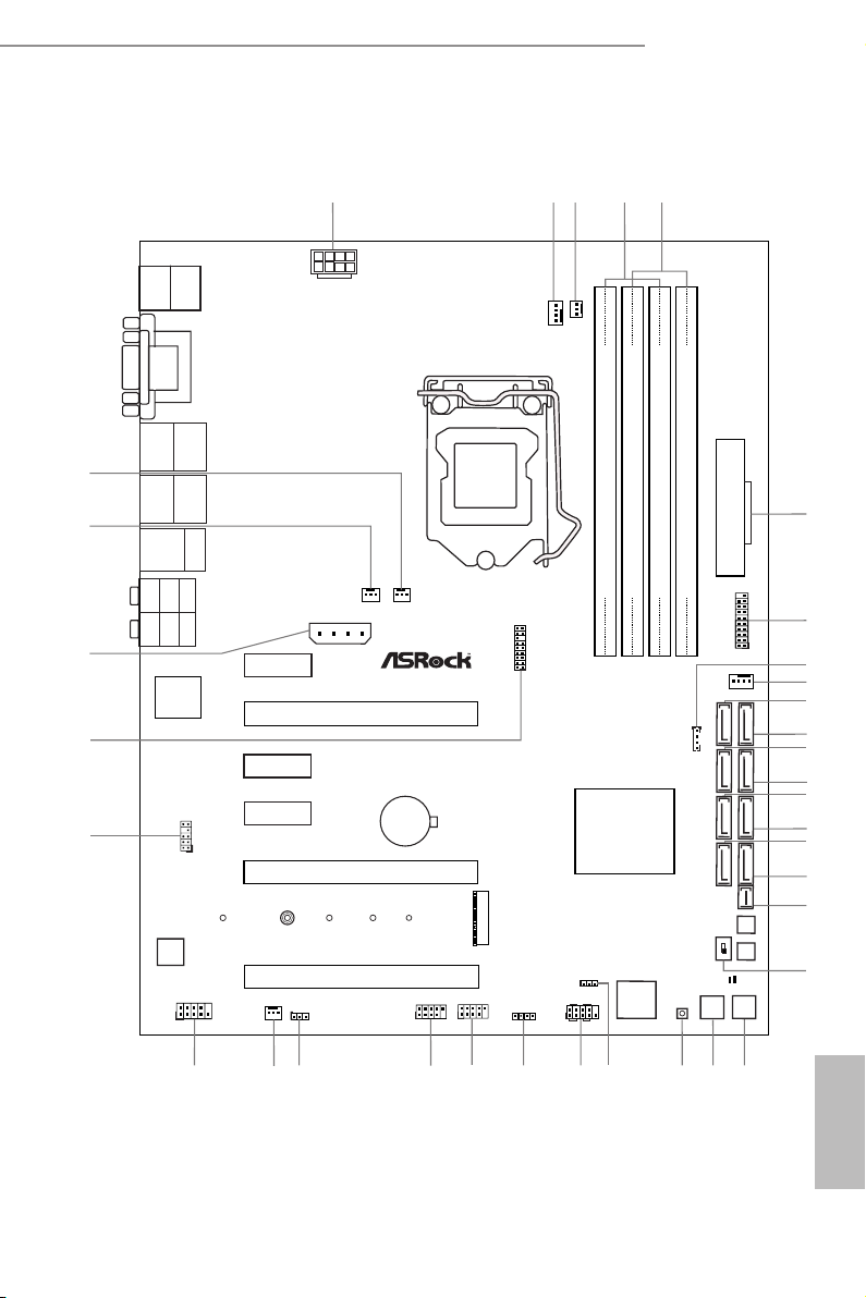
Motherboard Layout
Z97 Extreme4
English
1

English
No. Description
1 ATX 12V Power Connector (ATX12V1)
2 CPU Fan Connector (CPU_FAN1)
3 CPU Fan Connector (CPU_FAN2)
4 2 x 240-pin DDR3 DIMM Slots (DDR3_A1, DDR3_B1)
5 2 x 240-pin DDR3 DIMM Slots (DDR3_A2, DDR3_B2)
6 ATX Power Connector (ATXPWR1)
7 USB 3.0 Header (USB3_0_1)
8 HDD Saver Connector (SATA_PWR_1)
9 Chassis Fan Connector (CHA_FAN1)
10 SATA3 Connector (SATA3_A0)
11 SATA3 Connector (SATA3_A1)
12 SATA3 Connector (SATA3_0)
13 SATA3 Connector (SATA3_3)
14 SATA3 Connector (SATA3_1)
15 SATA3 Connector (SATA3_4)
16 SATA3 Connector (SATA3_2)
17 SATA3 Connector (SATA3_5)
18 SATA Express Connector (SATAE_1)
19 BIOS Selection Switch (BIOS_SEL1)
20 Power Switch (PWRBTN1)
21 Reset Switch (RSTBTN1)
22 Clear CMOS Switch
23 Power LED Header (PLED1)
24 System Panel Header (PANEL1)
25 Chassis Speaker Header (SPEAKER1)
26 USB 2.0 Header (USB4_5)
27 USB 2.0 Header (USB2_3)
28 Clear CMOS Jumper (CLRMOS1)
29 Power Fan Connector (PWR_FAN1)
30 COM Port Header (COM1)
31 Front Panel Audio Header (HD_AUDIO1)
32 TPM Header (TPMS1)
33 PCIe Power Connector (PCIE_PWR1)
2

No. Description
34 Chassis Fan Connector (CHA_FAN3)
35 Chassis Fan Connector (CHA_FAN2)
Z97 Extreme4
English
3
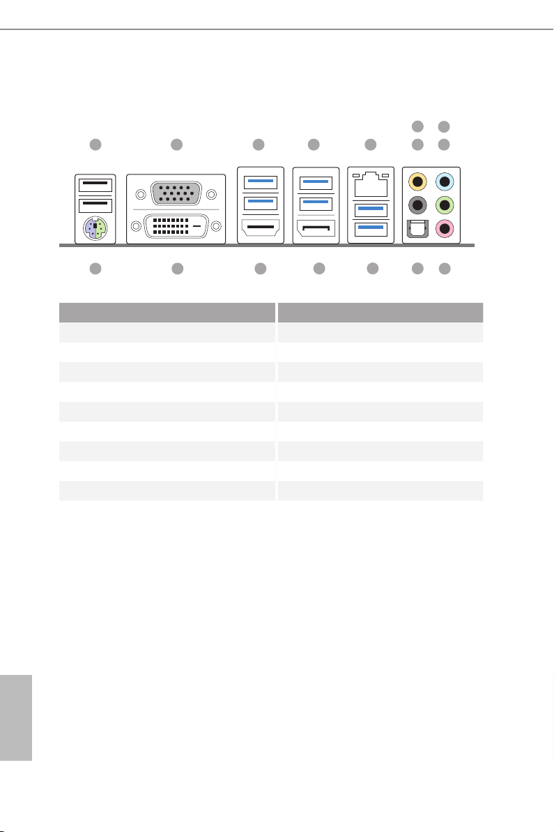
I/O Panel
6
8
1 2 3
1516
No. Description No. Description
1 USB 2.0 Ports (USB01) 10 Microphone (Pink)
2 D-Sub Port 11 Optical SPDIF Out Port
3 USB 3.0 Ports (USB3_45) (Intel® Z97) 12 USB 3.0 Ports (USB3_67)
4 USB 3.0 Ports (USB3_23) (Intel® Z97) (ASMedia ASM1042AE)
5 LAN RJ-45 Port* 13 DisplayPort 1.2
6 Central / Bass (Orange) 14 HDMI Port
7 Rear Speaker (Black) 15 DVI-D Port
8 Line In (Light Blue) 16 PS/2 Mouse/Keyboard Port
9 Front Speaker (Lime)**
14
13
54
12
7
11
9
10
English
4
Z97 Extreme4
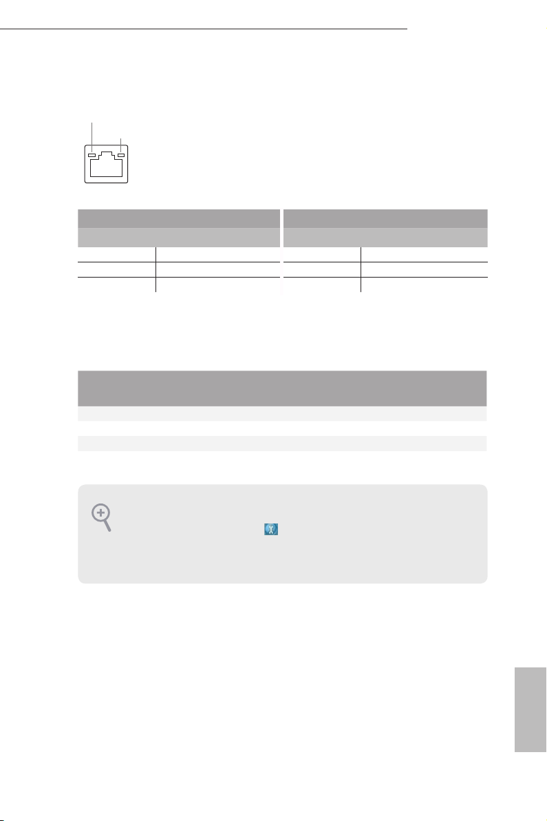
* ere are two LEDs on each LAN port. Please refer to the table below for the LAN port LED indications.
ACT/LINK LED
SPEED LED
LAN Por t
Activity / Link LED Speed LED
Status Description Status Description
O No Link O 10Mbps connection
Blinking Data Activity Orange 100Mbps connection
On Link Green 1Gbps connection
** If you use a 2- channel speaker, plea se connect the speake r’s plug into “Front Speaker Jack”. See the table below
for connection d etails in accordance w ith the type of speaker you use.
Audio Output
Channels
Front Speaker
(No. 9)
Rear Speaker
(No. 7)
Central / Bass
(No. 6)
2 V -- -- --
4 V V -- --
6 V V V --
8 V V V V
To enable Multi-Streaming, you need to connect a front panel audio cable to the front
panel audio header. Aer restarting your computer, you will nd the “Mixer” tool on your
system. Please select “Mixe r ToolBox” , click “Enable playback multi-streaming”, and
click “ok”. Choose “2CH”, “4CH”, “6CH”, or “8CH” and then you are allowed to select
“Realtek HDA Primary output” to use the Rear Speaker, Central/Ba ss, and Front Speaker,
or select “Realtek HDA Audio 2nd output” to use the front panel audio.
Line In
(No. 8)
English
5

Chapter 1 Introduction
ank you for purchasing ASRock Z97 Extreme4 motherboard, a reliable
motherboard produced under ASRock’s consistently stringent quality control.
It delivers excellent performance with robust design conforming to ASRock’s
commitment to quality and endurance.
Becau se the motherboard specications and the BIOS soware might be updated, the
content of this documentation will be subject to change without notice. In case any modications of this documentation occur, the updated version will be available on ASRock’s
website w ithout further notice. If you require technical support related to this motherboard, please visit our website for specic information about the model you are using. You
may nd the l atest VGA cards and CPU support list on ASRock’s website a s well. ASRock
website http://www.asrock.com.
1.1 Package Contents
•ASRock Z97 Extreme4 Motherboard (ATX Form Factor)
•ASRock Z97 Extreme4 Quick Installation Guide
•ASRock Z97 Extreme4 Support CD
•4 x Serial ATA (SATA) Data Cables (Optional)
•1 x HDD Saver Cable
•1 x I/O Shield
•1 x ASRock SLI_Bridge_2S Card
•1 x Screw for M.2 _SSD (NGFF) Socket 3
English
6

1.2 Specications
Z97 Extreme4
Platform
CPU
Chipset
Memory
Expansion
Slot
•ATX Form Factor
•High Density Glass Fabric PCB
•Supports 5th Generation, New 4
th
and 4th Generation Intel®
CoreTM i7/i5/i3/Pentium®/Celeron® Processors (Socket 1150)
•Digi Power design
•12 Power Phase design
•Supports Intel® Turbo Boost 2.0 Technology
•Supports Intel® K-Series unlocked CPUs
•Supports ASRock BCLK Full-range Overclocking
•Intel® Z97
•Dual Channel DDR3 Memory Technology
•4 x DDR3 DIMM Slots
•Supports DDR3 3200+(OC)/2933(OC)/2800(OC)/2400(OC)
/2133(OC)/1866(OC)/1600/1333/1066 non-ECC, un-buered
memory
•Max. capacity of system memory: 32GB
•Supports Intel® Extreme Memory Prole (XMP) 1.3 / 1.2
•15μ Gold Contact in DIMM Slots
•3 x PCI Express 3.0 x16 Slots (PCIE2/PCIE5/PCIE6: single
at x16 (PCIE2); dual at x8 (PCIE2) / x8 (PCIE5); triple at x8
(PCIE2) / x4 (PCIE5) / x4 (PCIE6)
•3 x PCI Express 2.0 x1 slots
•Supports AMD Quad CrossFireX
TM
, 3-Way CrossFireXTM and
CrossFireXTM
•Supports NVIDIA® Quad SLI
TM
and SLI
TM
•15μ Gold Contact in VGA PCIe Slot (PCIE2)
English
7

Graphics
•Intel® HD Graphics Built-in Visuals and the VGA outputs can
be supported only with processors which are GPU integrated.
•Supports Intel® HD Graphics Built-in Visuals : Intel® Quick
Sync Video with AVC, MVC (S3D) and MPEG-2 Full
HW Encode1, Intel® InTruTM 3D, Intel® Clear Video HD
Technology, Intel® InsiderTM, Intel® HD Graphics 4400/4600
•Pixel Shader 5.0, DirectX 11.1
•Max. shared memory 1792MB
•Four graphics output options: D-Sub, DVI-D, HDMI and
DisplayPort 1.2
•Supports Triple Monitor
•Supports HDMI with max. resolution up to 4K x 2K
(4096x2304) @ 24Hz
•Supports DVI-D with max. resolution up to 1920x1200 @
60Hz
•Supports D-Sub with max. resolution up to 1920x1200 @
60Hz
•Supports DisplayPort 1.2 with max. resolution up to 4K x 2K
(4096x2304) @ 24Hz or 4K x 2K (3840x2160) @ 60Hz
•Supports Auto Lip Sync, Deep Color (12bpc), xvYCC and
HBR (High Bit Rate Audio) with HDMI Port (Compliant
HDMI monitor is required)
•Supports HDCP with DVI-D, HDMI and DisplayPort 1.2
Ports
•Supports Full HD 1080p Blu-ray (BD) playback with DVI-D,
HDMI and DisplayPort 1.2 Ports
English
8
Audio
•7.1 CH HD Audio with Content Protection (Realtek ALC1150
Audio Codec)
•Premium Blu-ray Audio support
•Supports Surge Protection (ASRock Full Spike Protection)
•Supports Purity Sound
- Nichicon Fine Gold Series Audio Caps
- 115dB SNR DAC with Dierential Amplier
- TI® NE5532 Premium Headset Amplier (Supports up to
600 Ohm headsets)
- Direct Drive Technology
- EMI Shielding Cover|
- PCB Isolate Shielding|
•Supports DTS Connect
TM
2

Z97 Extreme4
LAN
Rear Panel
I/O
•Gigabit LAN 10/100/1000 Mb/s
•Giga PHY Intel® I218V
•Supports Intel® Remote Wake Technology
•Supports Wake-On-LAN
•Supports Lightning/ESD Protection (ASRock Full Spike
Protection)
•Supports Energy Ecient Ethernet 802.3az
•Supports PXE
•1 x PS/2 Mouse/Keyboard Port
•1 x D-Sub Port
•1 x DVI-D Port
•1 x HDMI Port
•1 x DisplayPort 1.2
•1 x Optical SPDIF Out Port
•2 x USB 2.0 Ports (Supports ESD Protection (ASRock Full
Spike Protection))
•2 x USB 3.0 Ports (ASMedia ASM1042AE) (Supports ESD
Protection (ASRock Full Spike Protection))
•4 x USB 3.0 Ports (Intel® Z97) (Supports ESD Protection
(ASRock Full Spike Protection))
•1 x RJ-45 LAN Port with LED (ACT/LINK LED and SPEED
LE D)
•HD Audio Jacks: Rear Speaker / Central / Bass / Line in /
Front Speaker / Microphone
Storage
•6 x SATA3 6.0 Gb/s Connectors by Intel® Z97, support RAID
(RAID 0, RAID 1, RAID 5, RAID 10, Intel Rapid Storage
Technology 12 and Intel Smart Response Technology), NCQ,
AHCI, Hot Plug and ASRock HDD Saver Technology
•2 x SATA3 6.0 Gb/s Connectors by ASMedia ASM1061, sup-
port NCQ, AHCI, Hot Plug and ASRock HDD Saver Technology
•1 x SATA Express Connector (shared with SATA3_4,
SATA3_5 and M.2 Socket)
*Support to be announced
•1 x M.2_SSD (NGFF) Socket 3, supports M.2 SATA3 6.0 Gb/s
module and M.2 PCI Express module up to Gen2 x2 (10 Gb/s)
English
9

Connector
•1 x COM Port Header
•1 x TPM Header
•1 x Power LED Header
•2 x CPU Fan Connectors (1 x 4-pin, 1 x 3-pin)
•3 x Chassis Fan Connectors (1 x 4-pin, 2 x 3-pin)
•1 x Power Fan Connector (3-pin)
•1 x 24 pin ATX Power Connector
•1 x 8 pin 12V Power Connector (Hi-Density Power
Conn ector)
•1 x HDD Saver Connector
•1 x PCIe Power Connector
•1 x Front Panel Audio Connector
•2 x USB 2.0 Headers (support 4 USB 2.0 ports) (Supports ESD
Protection (ASRock Full Spike Protection))
•1 x USB 3.0 Header (support 2 USB 3.0 ports) (Supports ESD
Protection (ASRock Full Spike Protection))
•1 x Dr. Debug with LED
•1 x Power Switch with LED
•1 x Reset Switch with LED
•1 x BIOS Selection Switch
English
10
BIOS
Feature
Hardware
•2 x 64Mb AMI UEFI Legal BIOS with multilingual GUI sup-
port (1 x Main BIOS and 1 x Backup BIOS)
•Supports Secure Backup UEFI Technology
•ACPI 1.1 Compliant wake up events
•SMBIOS 2.3.1 Support
•CPU, DRAM, PCH 1.05V, PCH 1.5V Voltage Multi-adjust-
ment
•CPU/Chassis temperature sensing
•CPU/Chassis/Power Fan Tachometer
•CPU/Chassis Quiet Fan (Auto adjust chassis fan speed by
CPU temperature)
•CPU/Chassis Fan multi-speed control
•Voltage monitoring: +12V, +5V, +3.3V, CPU Vcore, CPU
Input Voltage, CPU Internal Voltages
Z97 Extreme4
OS
•Microso® Windows® 8.1 32-bit / 8.1 64-bit / 8 32-bit / 8 64-
bit / 7 32-bit / 7 64-bit
Certications
* For detailed product information, please visit our website: http://www.asrock.com
Please realize that the re is a certain risk involved with overclocking, including adjusting
the setting in the BIOS, applying Untied Overclocking Technolog y, or using third-party
overclocking tools. O verclocking may aect your system’s stability, or even cause damage to
the components and devices of your system. It should be done at your ow n risk and expense.
We are not responsible for possible damage caused by overclocking.
Due to limitation, the actual memory size may be less than 4GB for the reservation for system usage under Windows® 32-bit operating systems. Windows® 64-bit operating systems
do not have such limitation s. You can use ASRock X Fast RAM to utilize the memor y that
Windows® cannot use.
•FCC, CE, WHQL
•ErP/EuP ready (ErP/EuP ready power supply is required)
11
English

Chapter 2 Installation
is is an ATX form factor motherboard. Before you install the motherboard, study
the conguration of your chassis to ensure that the motherboard ts into it.
Pre-installation Precautions
Take note of the following precautions before you install motherboard components
or change any motherboard settings.
•Make sure to unplug the power cord before installing or removing the motherboard
components. Failure to do so may cause physical injuries to you and damages to
motherboard components.
•In order to avoid damage from static electricity to the motherboard’s components,
NEVER place your motherboard directly on a carpet. Also remember to use a grounded
wrist strap or touch a safety grounded object before you handle the components.
•Hold components by the edges and do not touch the ICs.
•Whenever you uninstall any components, place them on a grounded anti-static pad or
in the bag that comes with the components.
•When placing screws to secure the motherboard to the chassis, please do not over-
tighten the screws! Doing so may damage the motherboard.
English
12
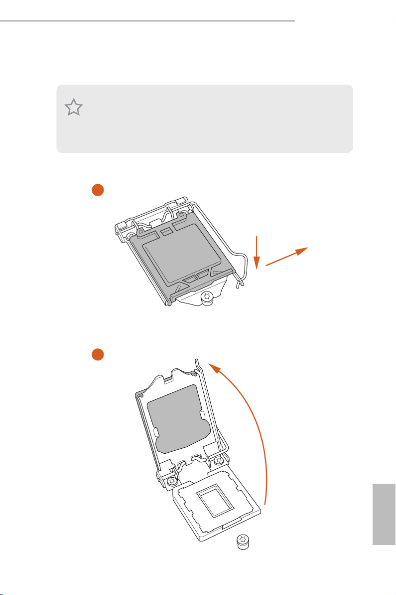
2.1 Installing the CPU
1. Before you insert the 1150-Pin CPU into the socket, please check if the PnP cap is on the
socket, if the CPU surface is unclean, or if there are any bent pins in the sock et. Do not
force to in sert the CPU into the socket if above situation is found. Otherwise, the CPU
will be seriously damaged.
2. Unplug all power cables before in stalling the CPU.
1
Z97 Extreme4
A
B
2
English
13
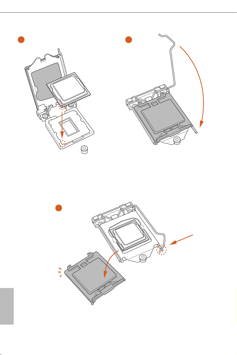
3
5
4
English
14

Z97 Extreme4
Please save and replace the cover if the processor i s removed. e cover must be placed if
you wish to return the motherboard for aer service.
15
English
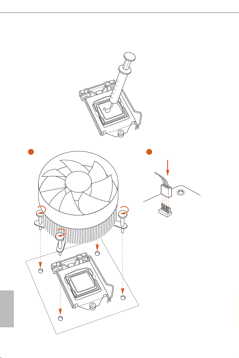
2.2 Installing the CPU Fan and Heatsink
1 2
English
16
N
FA
_
U
P
C
Z97 Extreme4
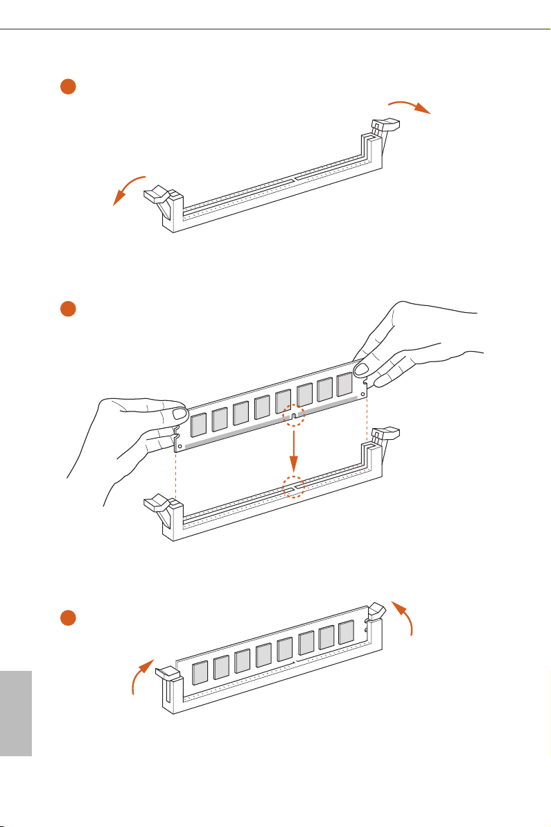
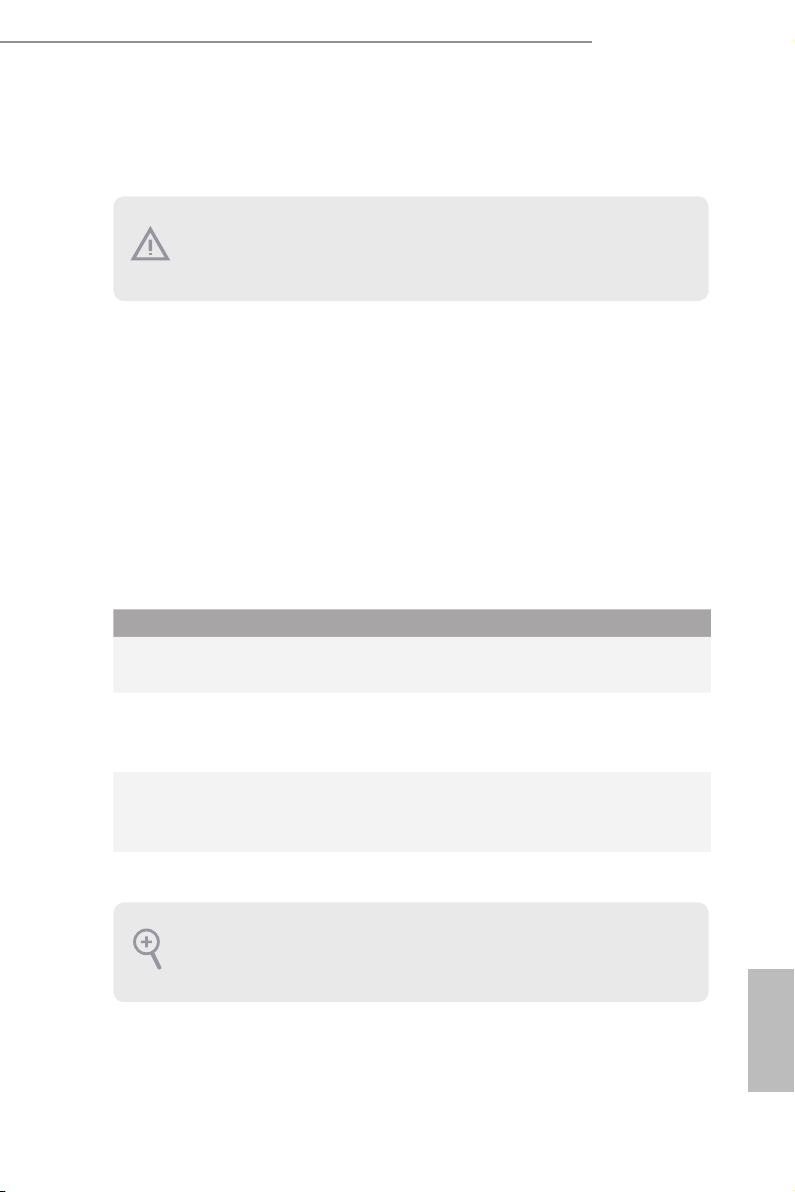
2.3 Installing Memory Modules (DIMM)
is motherboard provides four 240-pin DDR3 (Double Data Rate 3) DIMM slots,
and supports Dual Channel Memory Technology.
1. For dual channel conguration , you always need to in stall identical (the same brand,
speed , size and chip-type) DDR3 DIMM pairs.
2. It is unable to activate Dual Channel Memor y Technology with only one or three memor y
module installed.
3. It is not allowed to install a DDR or DDR2 memory module into a DDR3 slot; otherwise,
this motherboard and DIMM may be damaged.
Dual Channel Memory Conguration
Priority DDR3_A1 DDR3_A2 DDR3_B1 DDR3_B2
1 Populated Populated
2 Populated Populated
3 Populated Populated Populated Populated
e DIMM only ts in one correct orientation. It will cause permanent damage to the
motherboard and the DIMM if you force the DIMM into the slot at incorrect orientation.
English
17
1
2
English
18
3
2.4 Expansion Slots (PCI Express Slots)
ere are 6 PCI Express slots on the motherboard.
Before installing an ex pansion card, please make sure that the power supply is switched o
or the power cord is unplugged. Please read the documentation of the expansion card and
make necessary hardware settings for the card before you start the installation.
PCIe slots:
PCIE1 (PCIe 2.0 x1 slot) is used for PCI Express x1 lane width cards.
PCIE2 (PCIe 3.0 x16 slot) is used for PCI Express x16 lane width graphics cards.
PCIE3 (PCIe 2.0 x1 slot) is used for PCI Express x1 lane width cards.
PCIE4 (PCIe 2.0 x1 slot) is used for PCI Express x1 lane width cards.
PCIE5 (PCIe 3.0 x16 slot) is used for PCI Express x8 lane width graphics cards.
PCIE6 (PCIe 3.0 x16 slot) is used for PCI Express x4 lane width graphics cards.
PCIe Slot Congurations
PCIE2 PCIE5 PCIE6
Z97 Extreme4
Single Graphics Card x16 N/A N/A
Two Graphics Cards in
CrossFireXTM or SLITM Mode
ree Graphics Cards in
3-Way CrossFireXTM Mode
For a better ther mal environment, please connect a chassi s fan to the motherboard’s chassis fan connector (CHA_ FAN1, CHA_ FAN2 or CHA_FAN3) when using multiple graphics
cards.
x8 x8 N/A
x8 x4 x4
English
19

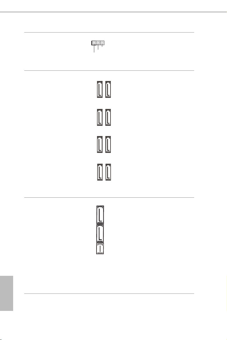
2.5 Jumpers Setup
e illustration shows how jumpers are setup. When the jumper cap is placed on
the pins, the jumper is “Short”. If no jumper cap is placed on the pins, the jumper
is “Open”. e illustration shows a 3-pin jumper whose pin1 and pin2 are “Short”
when a jumper cap is placed on these 2 pins.
Clear CMOS Jumper
(C LR MOS 1)
(see p.1, No. 28)
CLRMOS1 allows you to clear the data in CMOS. To clear and reset the system
parameters to default setup, please turn o the computer and unplug the power
cord from the power supply. Aer waiting for 15 seconds, use a jumper cap to
short pin2 and pin3 on CLRMOS1 for 5 seconds. However, please do not clear the
CMOS right aer you update the BIOS. If you need to clear the CMOS when you
just nish updating the BIOS, you must boot up the system rst, and then shut it
down before you do the clear-CMOS action. Please be noted that the password,
date, time, and user default prole will be cleared only if the CMOS battery is
removed.
Clear CMOSDefault
English
20
e Clear CMOS Switch has the same function a s the Clear CMOS jumper.
2.6 Onboard Headers and Connectors
Onboard headers and connectors are NOT jumpers. Do NOT place jumper caps over these
heade rs and connectors. Placing jumper caps over the headers and connectors will cause
permanent damage to the motherboard.
Z97 Extreme4
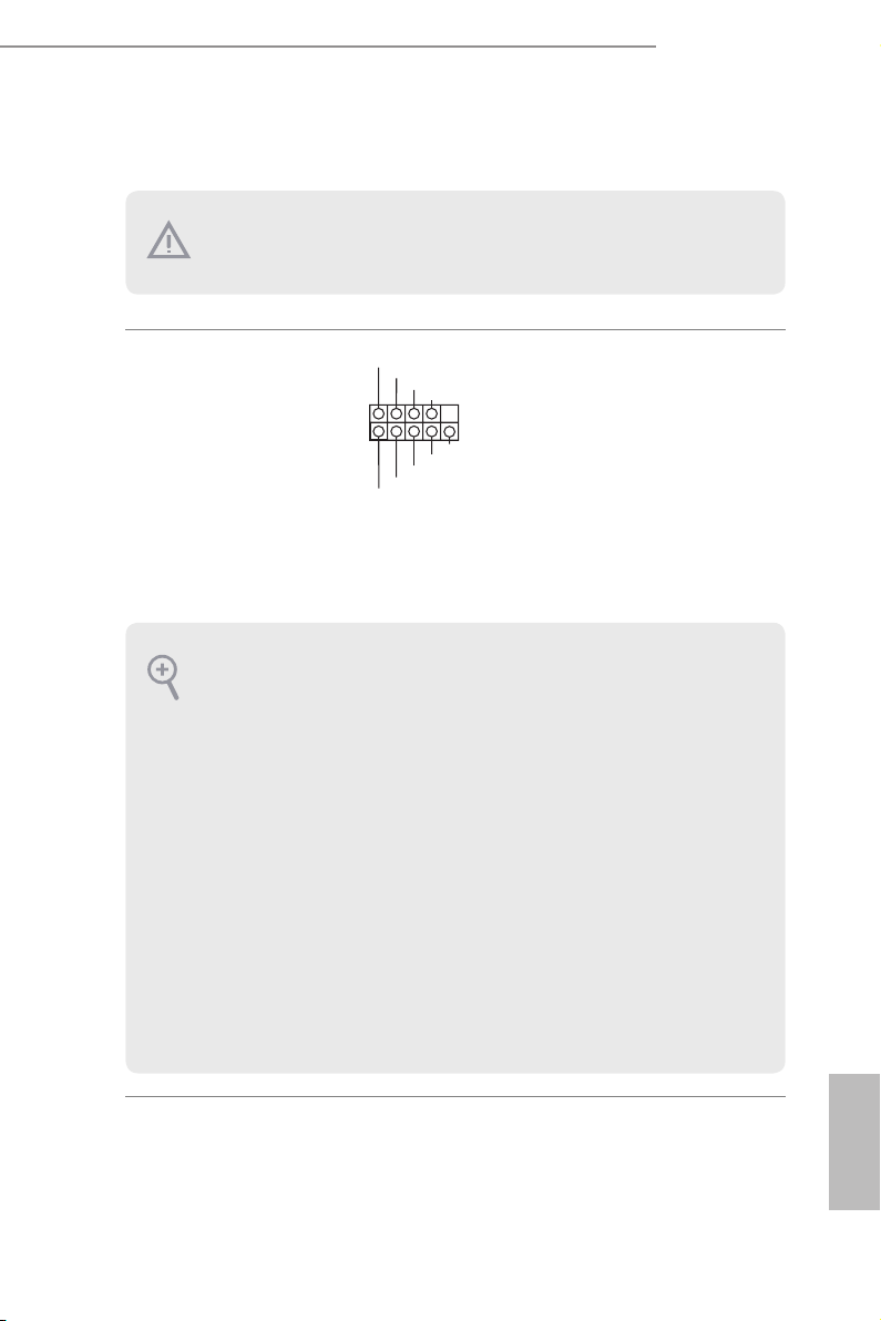
System Panel Header
(9-pi n PANEL1)
(see p.1, No. 24)
PWRBTN (Power Switch):
Connec t to the power switch on the chassi s front panel. You may congure the way to tur n
o your system using the power switch.
RESET (Reset Switch):
Connec t to the reset switch on the chassis front panel. Press the reset sw itch to restart the
computer if the computer f reezes and fails to perform a normal restar t.
PLED (Syste m Power LED):
Connec t to the power status indicator on the chassis front panel. e LED i s on when the
system is operating. e LED keeps blinking when the system is in S1/S3 sleep state. e
LED is o when the system is in S4 sleep state or powered o (S5).
HDLED (Ha rd Drive Activity LED):
Connec t to the hard drive activity LED on the chassis front panel. e LED is on when the
hard drive is reading or wr iting data.
e front panel design may dier by chassis. A front panel module mainly consists of power
switch, reset switch , power LED, hard dr ive activity LED, speaker and etc. When connecting your chassi s front panel module to thi s header, make sure the wire a ssignments and the
pin assignments are matched correctly.
1
PLED+
PLED-
HDLED-
HDLED+
PWRBTN#
GND
GND
RESET#
GND
Connect the power
switch, reset switch and
system status indicator on
the chassis to this header
according to the pin
assignments below. Note
the positive and negative
pins before connecting
the cables.
21
English
Power LED Header
(3-pin PL ED1)
(see p.1, No. 23)
1
PLED+
PLED+
PLED-
Please connect the chassis
power LED to this header
to
indicate the system’s
power status.
English
Serial ATA3 Connectors
(SATA3_ 0)
(see p.1, No. 12)
(SATA 3_1)
(see p.1, No. 14)
(SATA3_ 2)
(see p.1, No. 16)
(SATA 3_3)
(see p.1, No. 13)
(SATA3_4)
(see p.1, No. 15)
(SATA3_ 5)
(see p.1, No. 17)
(SATA3_ A0)
(see p.1, No. 10)
(SATA3_ A1)
(see p.1, No. 11)
Serial ATA Express
Connector
(S ATAE _ 1)
(see p.1, No. 18)
SATA3_A0
SATA3_0
SATA3_1
SATA3_2
SATAE_1 SATA3_4SATA3_5
ese eight SATA3
connectors support SATA
data cables for internal
SATA3_A1
storage devices with up to
6.0 Gb/s data transfer rate.
e SATA3_4, SATA3_5
are shared with the SATA
SATA3_3
Express connector.
To minimize the boot
time, use Intel® Z97 SATA
ports (SATA3_0) for your
SATA3_4
bootable devices.
SATA3_5
Please connect either
SATA or PCIe storage
devices to this connector.
e SATA Express
connector is shared with
the SATA3_4, SATA3_5
and the M.2_SSD (NGFF)
Socket 3.
*e SATA Express
interface is a combination
of SATAE_1, SATA3_4,
and SATA3_5.
22

Z97 Extreme4
USB 2.0 Headers
(9-pin USB2_3)
(see p.1, No. 27)
(9-pin USB4_5)
(see p.1, No. 26)
USB 3.0 Header
(19-pin USB3_0_1)
(see p.1, No. 7)
Front Panel Audio Header
(9-pin HD_ AUDIO1)
(see p.1, No. 31)
USB_PWR
1
USB_PWR
IntA_PA_SSRX-
IntA_PA_SSRX+
IntA_PA_SSTX-
IntA_PA_SSTX+
IntA_PA_D-
IntA_PA_D+
OUT_RET
MIC_RET
PRESENCE#
GND
Vbus
GND
GND
P-
P+
GND
DUMMY
Besides two USB 2.0 ports
on the I/O panel, there
are two headers on this
motherboard. Each USB
GND
P+
P-
VbusVbus
IntA_PB_SSRX-
IntA_PB_SSRX+
GND
IntA_PB_SSTX-
IntA_PB_SSTX+
GND
IntA_PB_D-
IntA_PB_D+
Dummy
1
OUT2_L
J_SENSE
1
2.0 header can support
two ports.
Besides six USB 3.0 ports
on the I/O panel, there
is one header on this
motherboard. Each USB
3.0 header can support
two ports.
is header is for
OUT2_R
MIC2_R
connecting audio devices
MIC2_L
to the front audio panel.
1. High Denition Audio support s Jack Sensing, but the panel wire on the chassis must sup port HDA to function correctly. Please follow the instructions in our manual and chassis
manual to install your system.
2. If you use an AC’97 audio panel , please install it to the front panel audio header by the
steps below:
A. Connect Mic_IN (MIC) to MIC2_ L.
B. Conne ct Audio_R (RIN) to OUT2_R and Audio_ L (LIN) to OUT2_ L.
C. Connect Ground (GND) to Ground (GND).
D. MIC_ RET and OUT_RET are for the HD audio panel only. You don’t need to connect
them for the AC’97 audio panel .
E. To activate the front mic, go to the “FrontMic” Tab in the Realtek Control panel and
adjust “Recording Volume”.
Chassis Speaker Header
(4-pin SPEAKER1)
(see p.1, No. 25)
DUMMY
1
+5V
SPEAKER
DUMMY
Please connect the chassis
speaker to this header.
English
23
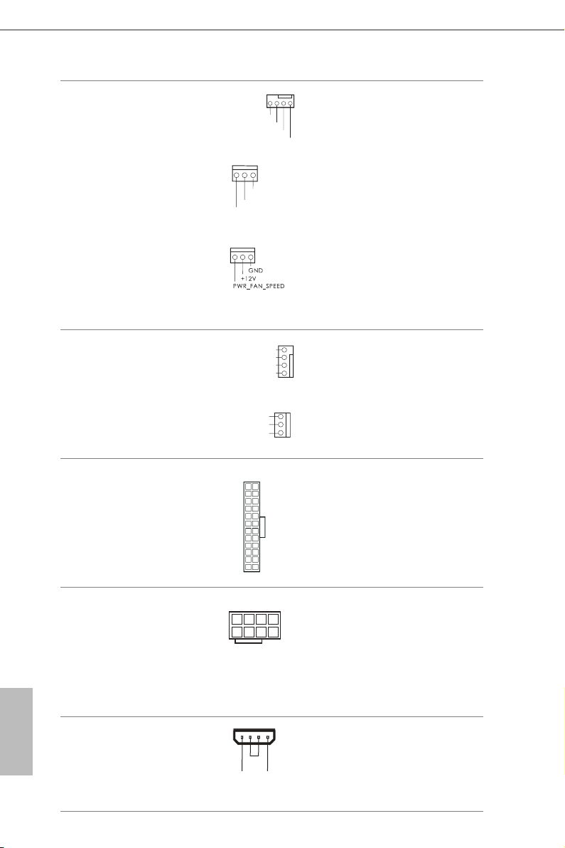
Chassis and Power Fan
Connectors
(4-pin CHA_FAN1)
(see p.1, No. 9)
(3-pi n CHA_FAN2)
(see p.1, No. 35)
(3-pi n CHA_FAN3)
(see p.1, No. 34)
(3-pin PW R_ FA N1)
(see p.1, No. 29)
FAN_SPEED_CONTROL
CHA_FAN_SPEED
GND
FAN_VOLTAGE
CHA_FA N_SPEED
+12V
Please connect fan cables
to the fan connectors and
match the black wire to
GND
the ground pin.
English
24
CPU Fan Connectors
(4-pin CPU_FAN1)
(see p.1, No. 2)
(3-pin CPU_FAN2)
(see p.1, No. 3)
ATX Power Connector
(24-pin ATXPWR1)
(see p.1, No. 6)
ATX 12V Power
Connector
(8-pin ATX12V1)
(see p.1, No. 1)
PCIe Power Connector
(4-pin PC IE_PWR1)
(see p.1, No. 33)
FAN_SPEED_CONTROL
FAN_SPEED
+12V
GND
FAN_SPEED
FAN_VOLTAGE
GND
12 124
1
5
GND
+12V DETECT
4
is motherboard pro-
3
2
vides a 4-Pin CPU fan
1
(Quiet Fan) connector.
If you plan to connect a
3-Pin CPU fan, please
connect it to Pin 1-3.
is motherboard provides a 24-pin ATX power
connector. To use a 20-pin
ATX power supply, please
plug it along Pin 1 and Pin
13
4
13.
is motherboard provides an 8-pin ATX 12V
8
power connector. To use a
4-pin ATX power supply,
please plug it along Pin 1
and Pin 5.
Please connect a 4 pin molex
power cable to this connector
when more than three graphics
cards are installed.

Z97 Extreme4
1
HDD Saver Connector
(4-pin SATA_ PWR _1)
(see p.1, No. 8)
Serial Port Header
(9-pin COM1)
(see p.1, No. 30)
TPM Header
(17-pi n TPMS1)
(see p.1, No. 32)
SER IR Q
S_P WR DWN #
GND
LAD 1
LAD 2
SMB _D ATA _M AI N
SMB _C LK_ MA IN
GND
1
RRXD1
DDCD#1
#
DDTR#1
DDSR#1
GND
TTXD1
CCTS#1
RRI#1
RRTS#1
1
Please connect the HDD Saver
Cable to this connector to
manage the power state of HDD.
is COM1 header
supports a serial port
module.
is connector supports
GNDGN D
Trusted Platform Module
+3V SB
(TPM) system, which
LAD 0
cansecurely store keys,
+3V
digital certicates,
LAD 3
passwords, and data. A
PCI RS T
#
FRA ME
TPM system also helps
K
PCI CL
enhance network security,
protects digital identities,
and ensures platform
in tegri ty.
English
25

2.7 Smart Switches
AB
e motherboard has four smart switches: Power Switch, Reset Switch, Clear CMOS
Switch and BIOS Selection Switch, allowing users to quickly turn on/o the system,
reset the system, clear the CMOS values or boot from dierent BIOS.
Power Switch
(P WR BT N1)
(see p.1, No. 20)
Reset Switch
(R ST BT N1)
(see p.1, No. 21)
Clear CMOS Switch
(C LRC BT N1)
(see p.1, No. 22)
is function i s workable only when you power o your computer and unplug the powe r
supply.
BIOS Selection Switch
(BIOS_SEL1)
(see p.1 No. 19)
Power Switch allows users
to quickly turn on/o the
system.
Reset Switch allows
RESET
users to quickly reset the
system.
Clear CMOS Switch
allows users to quickly
clear the CMOS values.
BIOS Selection Switch allows the
system to boot from either BIOS
A or BIOS B.
English
26
is motherboard has two BIOS chips, a primar y BIOS (BIOS_A) and a ba ckup BIOS (BIOS_
B), which enhances the safety and stability of your system. Normally, the system w ill work
on the primary BIOS. However, if the primary BIOS is corrupted or damaged, ju st ip the
BIOS Selection Sw itch to “B”, then the backup BIOS will take over on the next system boot.
Aer that, use “Secure Backup U EFI” in the UEFI Setup Utility to duplicate a working copy
of the BIOS les to the primary BIOS to ensure normal system operation. For safety issues,
users are not able to update the backup BIOS manu ally. Users may refer to the BIOS LEDs
(BIOS_ A_LED or BIOS_B_ LED) to identify which BIOS i s currently activated.

Z97 Extreme4
2.8 Dr. Debug
Dr. Debug is used to provide code information, which makes troubleshooting even
easier. Please see the diagrams below for reading the Dr. Debug codes.
Code Description
00 Please check if the CPU is installed correctly and then clear
CMOS.
0d Problem related to memory, VGA card or other devices.
Please clear CMOS, re-install the memory and VGA card,
and remove other USB, PCI devices.
01 - 54
(exce pt 0d),
5A- 60
55 e Memory could not be detected. Please re-install the
61 - 91 Chipset initialization error. Please press reset or clear
92 - 99 Problem related to PCI-E devices. Please re-install PCI-E
A0 - A7 Problem related to IDE or SATA devices. Please re-install
b0 Problem related to memory. Please re-install the CPU and
Problem related to memory. Please re-install the CPU and
memory then clear CMOS. If the problem still exists, please
install only one memory module or try using other memory
modules.
memory and CPU. If the problem still exists, please install
only one memory module or try using other memory
modules.
CMOS.
devices or try installing them in other slots. If the problem
still exists, please remove all PCI-E devices or try using
another VGA card.
IDE and SATA devices. If the problem still exists, please
clear CMOS and try removing all SATA devices.
memory. If the problem still exists, please install only one
memory module or try using other memory modules.
English
27

b4 Problem related to USB devices. Please try removing all
USB devices.
b7 Problem related to memory. Please re-install the CPU and
memory then clear CMOS. If the problem still exists, please
install only one memory module or try using other memory
modules.
d6 e VGA could not be recognized. Please clear CMOS and
try re-installing the VGA card. If the problem still exists,
please try installing the VGA card in other slots or use other
VGA c ards.
d7 e Keyboard and mouse could not be recognized. Please
try re-installing the keyboard and mouse.
d8 Invalid Password.
FF Please check if the CPU is installed correctly and then clear
CMOS.
English
28
 Loading...