

Page 1

Version 1.0
Published May 2014
Copyright©2014 ASRock INC. All rights reserved.
Copyright Notice:
No part of this documentation may be reproduced, transcribed, transmitted, or
translated in any language, in any form or by any means, except duplication of
documentation by the purchaser for backup purpose, without written consent of
ASRock Inc.
Products and corporate names appearing in this documentation may or may not
be registered trademarks or copyrights of their respective companies, and are used
only for identication or explanation and to the owners’ benet, without intent to
infringe.
Disclaimer:
Specications and information contained in this documentation are furnished for
informational use only and subject to change without notice, and should not be
constructed as a commitment by ASRock. ASRock assumes no responsibility for
any errors or omissions that may appear in this documentation.
With respect to the contents of this documentation, ASRock does not provide
warranty of any kind, either expressed or implied, including but not limited to
the implied warranties or conditions of merchantability or tness for a particular
purpose.
In no event shall ASRock, its directors, ocers, employees, or agents be liable for
any indirect, special, incidental, or consequential damages (including damages for
loss of prots, loss of business, loss of data, interruption of business and the like),
even if ASRock has been advised of the possibility of such damages arising from any
defect or error in the documentation or product.
is device complies with Part 15 of the FCC Rules. Operation is subject to the following
two conditions:
(1) this device may not cause harmful interference, and
(2) this device must accept any interference received, including interference that
may cause undesired operation.
CALIFORNIA, USA ONLY
e Lithium battery adopted on this motherboard contains Perchlorate, a toxic substance
controlled in Perchlorate Best Management Practices (BMP) regulations passed by the
California Legislature. When you discard the Lithium battery in California, USA, please
follow the related regulations in advance.
“Perchlorate Material-special handling may apply, see www.dtsc.ca.gov/hazardouswaste/
perchlorate”
ASRock Website: http://www.asrock.com
Page 2

e terms HDMI™ and HDMI High-Denition Multimedia Interface, and the HDMI
logo are trademarks or registered trademarks of HDMI Licensing LLC in the United
States and other countries.
Manufactured under license under U.S. Patent Nos: 5,956,674; 5,974,380; 6,487,535;
7,003,467 & other U.S. and worldwide patents issued & pending. DTS, the Symbol, &
DTS and the Symbol together is a registered trademark & DTS Connect, DTS Interactive,
DTS Neo:PC are trademarks of DTS, Inc. Product includes soware.
© DTS, Inc., All Rights Reserved.
Page 3

Intel
Z97
DDR 3_A1 (6 4 bit, 24 0-pin m odule )
DDR 3_A2 (6 4 bit, 24 0-pin m odule )
DDR 3_B1 (6 4 bit, 24 0-pin m odule )
DDR 3_B2 (6 4 bit, 24 0-pin m odule )
ATXP WR1
Reset
Power
Supe r
I/O
PANEL1
HDLED RESET
PLED PWRBTN
1
SPEAKER1
1
PLED1
1
CHA_FAN2
CHA_FAN1
CPU_FAN2
CHA_FAN4
8-La yer PCB
Top:
Central/B ass
Top:
LINE IN
USB 2.0
T: USB2
B: USB3
Clr
CMOS
USB 3.0
T: USB0
B: USB1
Top:
RJ-45
USB 3.0
T: USB2
B: USB3
USB 3.0
T: USB4
B: USB5
Center:
REAR SPK
Center:
FRONT
Bottom:
Optical
SPDIF
Bottom:
MIC IN
+
CPU_FAN1
5
6
-
10
12
18
USB 2.0
T: USB0
B: USB1
HDMI1
ON
1 2 3 4
ON
OFF
USB3_6_7
24
USB4_5
1
CLRMOS1
1
BIOS_SEL 1
AB
BIOS_B_LED
64Mb
BIOS
BIOS_B
64Mb
BIOS
BIOS_A
BIOS_A_LED
PS2
Keybo ard
/Mous e
MENU
ON
OFF
ATX12V1
ATX12V3
SATAE_1
SATA3_A1
SATA3_A2
SATA3_1
SATA3_4
SATA3_0
SATA3_3
SATA3_2
SATA3_5
PWR_FAN1
COM1
1
PCIE_PWR1
1
TPMS1
1
HD_AUDIO1
Purity
Sound 2
TM
T B1
1
Dr.
Debug
SATA_PWR_1
1
Killer
E2200
PCIE3
PCIE2
PCIE4
Z97 OC Formula
CMOS
Battery
PCIE6
NUT1
NUT2NUT3NUT4
M2
RoHS
PCIE1
PCIE5
NUT5
LN2MODE
SLOWMODE
PCIE_SWITCH
CHA_FAN3
2
1
3
4
8
7
9
11
13
14
15
16
17
25
27
28
3032
36
37
38
39
40
41
19
20
21
22
26
29
3133
34
35
42
43
44
23
CPU
DRAM
VGA
BOOT
Motherboard Layout
Z97 OC Formula
English
1
Page 4

English
No. Description
1 ATX 12V Power Connector (ATX12V3)
2 ATX 12V Power Connector (ATX12V1)
3 CPU Fan Connector (CPU_FAN1)
4 CPU Fan Connector (CPU_FAN2)
5 2 x 240-pin DDR3 DIMM Slots (DDR3_A1, DDR3_B1)
6 2 x 240-pin DDR3 DIMM Slots (DDR3_A2, DDR3_B2)
7 V-ProbeTM (VOL _CON1, VOL _CON2)
8 ATX Power Connector (ATXPWR1)
9 USB 3.0 Header (USB3_6_7)
10 SATA3 Connector (SATA3_A1)
11 SATA3 Connector (SATA3_A2)
12 SATA3 Connector (SATA3_0)
13 SATA3 Connector (SATA3_3)
14 SATA3 Connector (SATA3_1)
15 SATA3 Connector (SATA3_4)
16 SATA3 Connector (SATA3_2)
17 SATA3 Connector (SATA3_5)
18 SATA Express Connector (SATAE_1)
19 Slow Mode Switch (SLOWMODE)
20 BIOS Selection Switch (BIOS_SEL1)
21 System Panel Header (PANEL1)
22 Chassis Speaker Header (SPEAKER1)
23 Post Status Checker (PSC)
24 Power Switch (PWR)
25 Reset Switch (RST)
26 Power LED Header (PLED1)
27 Rapid OC Button (+) (PLUS)
28 Rapid OC Button (–) (MINUS)
29 HDD Saver Connector (SATA_PWR_1)
30 Menu Button (MENU)
31 LN2 Mode Switch (LN2MODE)
32 Chassis Fan Connector (CHA_FAN2)
33 PCIe ON/OFF Switch (PCIE_SWITCH)
2
Page 5

No. Description
34 underbolt AIC Connector (TB1)
35 USB 2.0 Header (USB4_5)
36 Power Fan Connector (PWR_FAN1)
37 Chassis Fan Connector (CHA_FAN1)
38 TPM Header (TPMS1)
39 COM Port Header (COM1)
40 PCIe Power Connector (PCIE _PWR1)
41 Front Panel Audio Header (HD_AUDIO1)
42 Clear CMOS Jumper (CLRMOS1)
43 Chassis Fan Connector (CHA_FAN3)
44 Chassis Fan Connector (CHA_FAN4)
Z97 OC Formula
English
3
Page 6

1.4 I/O Panel
8
10
1 2 3
15
No. Description No. Description
1 USB 2.0 Ports (USB01) 9 Rear Speaker (Black)
2 HDMI Port 10 Line In (Light Blue)
3 USB 3.0 Ports (USB3_01) 11 Front Speaker (Lime)**
4 Clear CMOS Switch (CLRCBTN1) 12 Microphone (Pink)
5 USB 3.0 Ports (USB3_23) 13 Optical SPDIF Out Port
6 USB 2.0 Ports (USB23) 14 USB 3.0 Ports (USB3_45)
7 LAN RJ-45 Port* 15 PS/2 Mouse/Keyboard Port
8 Central / Bass (Orange)
4
5
6
7
14
9
13
11
12
English
4
Page 7

Z97 OC Formula
* ere are two LEDs on each LAN port. Please refer to the table below for the LAN port LED indications.
ACT/LINK LED
SPEED LED
LAN Por t
Activity / Link LED Speed LED
Status Description Status Description
O No Link O 10Mbps connection
Blinking Data Activity Orange 100Mbps connection
On Link Green 1Gbps connection
** If you use a 2- channel speaker, plea se connect the speake r’s plug into “Front Speaker Jack”. See the table below
for connection d etails in accordance w ith the type of speaker you use.
Audio Output
Channels
Front Speaker
(N o. 11)
Rear Speaker
(No. 9)
Central / Bass
(No. 8)
2 V -- -- --
4 V V -- --
6 V V V --
8 V V V V
To enable Multi-Streaming, you need to connect a front panel audio cable to the front
panel audio header. Aer restarting your computer, you will nd the “Mixer” tool on your
system. Please select “Mixe r ToolBox” , click “Enable playback multi-streaming”, and
click “ok”. Choose “2CH”, “4CH”, “6CH”, or “8CH” and then you are allowed to select
“Realtek HDA Primary output” to use the Rear Speaker, Central/Ba ss, and Front Speaker,
or select “Realtek HDA Audio 2nd output” to use the front panel audio.
Line In
(No. 10)
English
5
Page 8

Chapter 1 Introduction
ank you for purchasing ASRock Z97 OC Formula motherboard, a reliable
motherboard produced under ASRock’s consistently stringent quality control.
It delivers excellent performance with robust design conforming to ASRock’s
commitment to quality and endurance.
Becau se the motherboard specications and the BIOS soware might be updated, the
content of this documentation will be subject to change without notice. In case any modications of this documentation occur, the updated version will be available on ASRock’s
website w ithout further notice. If you require technical support related to this motherboard, please visit our website for specic information about the model you are using. You
may nd the l atest VGA cards and CPU support list on ASRock’s website a s well. ASRock
website http://www.asrock.com.
1.1 Package Contents
•ASRock Z97 OC Formula Motherboard (ATX Form Factor)
•ASRock Z97 OC Formula Quick Installation Guide
•ASRock Z97 OC Formula Support CD
•1 x I/O Shield
•4 x Serial ATA (SATA) Data Cables (Optional)
•1 x ASRock Flexible SLI Bridge Connector Cable
•1 x HDD Saver Cable
•1 x Screw for M.2 _SSD (NGFF) Socket 3
English
6
Page 9

1.2 Specications
Z97 OC Formula
Platform
CPU
Chipset
Memory
Expansion
Slot
•ATX Form Factor
•High Density Glass Fabric PCB
•Supports 5
th
Generation, New 4th and 4th Generation Intel®
Core™ i7/i5/i3/Pentium®/Celeron® Processors (Socket 1150)
•Digi Power design
•12 Power Phase design
•Supports Intel® Turbo Boost 2.0 Technology
•Supports Intel® K-Series unlocked CPUs
•Supports ASRock BCLK Full-range Overclocking
•Intel® Z97
•Dual Channel DDR3 Memory Technology
•4 x DDR3 DIMM Slots
•Supports DDR3 3400+(OC)/2933(OC)/2800(OC)/2400(OC)
/2133(OC)/1866(OC)/1600/1333/1066 non-ECC, un-buered
memory
•Max. capacity of system memory: 32GB
•Supports Intel® Extreme Memory Prole (XMP) 1.3 / 1.2
•3 x PCI Express 3.0 x16 Slots (PCIE1/PCIE2/PCIE4: single
at x16 (PCIE1); dual at x8 (PCIE1) / x8 (PCIE4); triple at x8
(PCIE1) / x4 (PCIE2) / x4 (PCIE4))
•1 x PCI Express 2.0 x16 Slot (PCIE6: x4 mode)
•2 x PCI Express 2.0 x1 Slots
•Supports AMD Quad CrossFireX
TM
, 4-Way CrossFireXTM,
3-Way CrossFireXTM and CrossFireXTM
•Supports NVIDIA® Quad SLI
TM
and SLI
TM
English
7
Page 10

Graphics
•Intel® HD Graphics Built-in Visuals and the VGA outputs can
be supported only with processors which are GPU integrated.
•Supports Intel® HD Graphics Built-in Visuals : Intel® Quick
Sync Video with AVC, MVC (S3D) and MPEG-2 Full
HW Encode1, Intel® InTruTM 3D, Intel® Clear Video HD
Technology, Intel® InsiderTM, Intel® HD Graphics 4400/4600
•Pixel Shader 5.0, DirectX 11.1
•Max. shared memory 1792MB
•Supports HDMI with max. resolution up to 4K x 2K
(4096x2304) @ 24Hz
•Supports Auto Lip Sync, Deep Color (12bpc), xvYCC and
HBR (High Bit Rate Audio) with HDMI Port
(Compliant HDMI monitor is required)
•Supports HDCP with HDMI Port
•Supports Full HD 1080p Blu-ray (BD) playback with HDMI
Port
English
Audio
LAN
•7.1 CH HD Audio with Content Protection (Realtek ALC1150
Audio Codec)
•Premium Blu-ray Audio support
•Supports Surge Protection (ASRock Full Spike Protection)
•Supports Purity Sound
TM
2
- Nichicon Fine Gold Series Audio Caps
- 115dB SNR DAC with Dierential Amplier
- TI® NE5532 Premium Headset Amplier (Supports up to
600 Ohm headsets)
- Direct Drive Technology
- EMI Shielding Cover
- PCB Isolate Shielding
•Supports DTS Connect
•PCIE x1 Gigabit LAN 10/100/1000 Mb/s
•Qualcomm® Atheros® Killer
TM
E2200 Series
•Supports Qualcomm® Atheros® Security Wake On Internet
Tech nolo gy
•Supports Wake-On-LAN
•Supports Lightning/ESD Protection (ASRock Full Spike
Protection)
•Supports Energy Ecient Ethernet 802.3az
•Supports PXE
8
Page 11

Z97 OC Formula
Rear Panel
I/O
Storage
•1 x PS/2 Mouse/Keyboard Port
•1 x HDMI Port
•1 x Optical SPDIF Out Port
•4 x USB 2.0 Ports
•4 x USB 3.0 Ports (ASMedia ASM1074 hub) (Supports ESD
Protection (ASRock Full Spike Protection))
•2 x USB 3.0 Ports (Intel® Z97) (Supports ESD Protection
(ASRock Full Spike Protection))
•1 x RJ-45 LAN Port with LED (ACT/LINK LED and SPEED
LE D)
•1 x Clear CMOS Switch
•HD Audio Jacks: Rear Speaker / Central / Bass / Line in /
Front Speaker / Microphone
•6 x SATA3 6.0 Gb/s Connectors by Intel® Z97, support RAID
(RAID 0, RAID 1, RAID 5, RAID 10, Intel Rapid Storage
Technology 13 and Intel Smart Response Technology), NCQ,
AHCI, Hot Plug and ASRock HDD Saver Technology
•2 x SATA3 6.0 Gb/s Connectors by ASMedia ASM1061, sup-
port NCQ, AHCI, Hot Plug and ASRock HDD Saver Technology
•1 x SATA Express Connector (shared with SATA3_4,
SATA3_5 and M.2 Socket)
* Support to be announced
•1 x M.2_SSD (NGFF) Socket 3, supports M.2 SATA3 6.0 Gb/s
module and M.2 PCI Express module up to Gen2 x2 (10 Gb/s)
English
9
Page 12

Connector
•1 x COM Port Header
•1 x TPM Header
•1 x Power LED header
•2 x CPU Fan Connectors (1 x 4-pin, 1 x 3-pin)
•4 x Chassis Fan Connectors (1 x 4-pin, 3 x 3-pin)
•1 x Power Fan Connector (3-pin)
•1 x 24 pin ATX Power Connector
•2 x 8 pin 12V Power Connectors (Hi-Density Power
Conn ector)
•1 x HDD Saver Connector
•1 x PCIe Power Connector
•1 x Front Panel Audio Connector
•1 x underbolt AIC Connector
•1 x USB 2.0 Header (Supports 2 USB 2.0 ports) (Supports ESD
Protection (ASRock Full Spike Protection))
•1 x USB 3.0 Header (Supports 2 USB 3.0 ports) (Supports ESD
Protection (ASRock Full Spike Protection))
•1 x Power Switch with LED
•1 x Reset Switch with LED
•V-Probe
•Rapid OC Buttons: +/- buttons to adjust OC frequency
•1 x Menu Button
•1 x PCIe ON/OFF Switch
•1 x Post Status Checker (PSC)
•1 x Slow Mode Switch
•1 x LN2 Mode Switch
•1 x BIOS Selection Switch
laid
TM
: 2 x 7-set of onboard voltage measurement points
English
10
BIOS
Feature
•2 x 64Mb AMI UEFI Legal BIOS with multilingual GUI sup-
port (1 x Main BIOS and 1 x Backup BIOS)
•Supports Secure Backup UEFI Technology
•ACPI 1.1 Compliant wake up events
•SMBIOS 2.3.1 Support
•CPU, DRAM, PCH 1.05V, PCH 1.5V Voltage Multi-adjust-
ment
Page 13

Z97 OC Formula
Hardware
•CPU/Chassis temperature sensing
•CPU/Chassis/Power Fan Tachometer
•CPU/Chassis Quiet Fan (Auto adjust chassis fan speed by
CPU temperature)
•CPU/Chassis Fan multi-speed control
•Multi ermal Sensor
•Voltage monitoring: +12V, +5V, +3.3V, CPU Input Voltage,
CPU Internal Voltages
OS
•Microso® Windows® 10 64-bit / 8.1 32-bit / 8.1 64-bit / 8 32-
bit / 8 64-bit / 7 32-bit / 7 64-bit
Certications
* For detailed product information, please visit our website: http://www.asrock.com
Please realize that the re is a certain risk involved with overclocking, including adjusting
the setting in the BIOS, applying Untied Overclocking Technolog y, or using third-party
overclocking tools. O verclocking may aect your system’s stability, or even cause damage to
the components and devices of your system. It should be done at your ow n risk and expense.
We are not responsible for possible damage caused by overclocking.
•FCC, CE, WHQL
•ErP/EuP ready (ErP/EuP ready power supply is required)
Due to limitation, the actual memory size may be less than 4GB for the reservation for system usage under Windows® 32-bit operating systems. Windows® 64-bit operating systems
do not have such limitation s. You can use ASRock X Fast RAM to utilize the memor y that
Windows® cannot use.
English
11
Page 14

Chapter 2 Installation
is is an ATX form factor motherboard. Before you install the motherboard, study
the conguration of your chassis to ensure that the motherboard ts into it.
Pre-installation Precautions
Take note of the following precautions before you install motherboard components
or change any motherboard settings.
•Make sure to unplug the power cord before installing or removing the motherboard
components. Failure to do so may cause physical injuries to you and damages to
motherboard components.
•In order to avoid damage from static electricity to the motherboard’s components,
NEVER place your motherboard directly on a carpet. Also remember to use a grounded
wrist strap or touch a safety grounded object before you handle the components.
•Hold components by the edges and do not touch the ICs.
•Whenever you uninstall any components, place them on a grounded anti-static pad or
in the bag that comes with the components.
•When placing screws to secure the motherboard to the chassis, please do not over-
tighten the screws! Doing so may damage the motherboard.
English
12
Page 15

2.1 Installing the CPU
1. Before you insert the 1150-Pin CPU into the socket, please check if the PnP cap is on the
socket, if the CPU surface is unclean, or if there are any bent pins in the sock et. Do not
force to in sert the CPU into the socket if above situation is found. Otherwise, the CPU
will be seriously damaged.
2. Unplug all power cables before in stalling the CPU.
1
Z97 OC Formula
A
B
2
English
13
Page 16

3
5
4
English
14
Page 17

Z97 OC Formula
Please save and replace the cover if the processor i s removed. e cover must be placed if
you wish to return the motherboard for aer service.
15
English
Page 18

2.2 Installing the CPU Fan and Heatsink
1 2
English
16
N
FA
_
U
P
C
Page 19

Z97 OC Formula
2.3 Installing Memory Modules (DIMM)
is motherboard provides four 240-pin DDR3 (Double Data Rate 3) DIMM slots,
and supports Dual Channel Memory Technology.
1. For dual channel conguration , you always need to in stall identical (the same brand,
speed , size and chip-type) DDR3 DIMM pairs.
2. It is unable to activate Dual Channel Memor y Technology with only one or three memor y
module installed.
3. It is not allowed to install a DDR or DDR2 memory module into a DDR3 slot; otherwise,
this motherboard and DIMM may be damaged.
Dual Channel Memory Conguration
Priority DDR3_A1 DDR3_A2 DDR3_B1 DDR3_B2
1 Populated Populated
2 Populated Populated
3 Populated Populated Populated Populated
e DIMM only ts in one correct orientation. It will cause permanent damage to the
motherboard and the DIMM if you force the DIMM into the slot at incorrect orientation.
English
17
Page 20

1
2
English
18
3
Page 21

Z97 OC Formula
2.4 Expansion Slots (PCI Express Slots)
ere are 6 PCI Express slots on the motherboard.
Before installing an ex pansion card, please make sure that the power supply is switched o
or the power cord is unplugged. Please read the documentation of the expansion card and
make necessary hardware settings for the card before you start the installation.
PCIe slots:
PCIE1 (PCIe 3.0 x16 slot) is used for PCI Express x16 lane width graphics cards.
PCIE2 (PCIe 3.0 x16 slot) is used for PCI Express x4 lane width graphics cards.
PCIE3 (PCIe 2.0 x1 slot) is used for PCI Express x1 lane width cards.
PCIE4 (PCIe 3.0 x16 slot) is used for PCI Express x8 lane width graphics cards.
PCIE5 (PCIe 2.0 x1 slot) is used for PCI Express x1 lane width cards.
PCIE6 (PCIe 2.0 x16 slot) is used for PCI Express x4 lane width graphics cards.
PCIe Slot Congurations
PCIE1 PCIE2 PCIE4 PCIE6
Single Graphics Card x16 N/A N/A N/A
Two Graphics Cards in
CrossFireXTM or SLITM Mode
ree Graphics Cards in
3-Way CrossFireXTM Mode
Four Graphics Cards in
4-Way CrossFireXTM Mode
For a better ther mal environment, please connect a chassi s fan to the motherboard’s chassis fan connector (CHA_ FAN1, CHA_ FAN2, CHA_FAN3 or CHA_ FAN4) when u sing
multiple graphics cards.
x8 N/A x8 N /A
x8 x4 x4 N/A
x8 x4 x4 x4
English
19
Page 22

2.5 Jumpers Setup
e illustration shows how jumpers are setup. When the jumper cap is placed on
the pins, the jumper is “Short”. If no jumper cap is placed on the pins, the jumper
is “Open”. e illustration shows a 3-pin jumper whose pin1 and pin2 are “Short”
when a jumper cap is placed on these 2 pins.
Clear CMOS Jumper
(C LR MOS 1)
(see p.1, No. 42)
CLRMOS1 allows you to clear the data in CMOS. To clear and reset the system
parameters to default setup, please turn o the computer and unplug the power
cord from the power supply. Aer waiting for 15 seconds, use a jumper cap to
short pin2 and pin3 on CLRMOS1 for 5 seconds. However, please do not clear the
CMOS right aer you update the BIOS. If you need to clear the CMOS when you
just nish updating the BIOS, you must boot up the system rst, and then shut it
down before you do the clear-CMOS action. Please be noted that the password,
date, time, and user default prole will be cleared only if the CMOS battery is
removed.
Clear CMOSDefault
English
20
e Clear CMOS Switch has the same function a s the Clear CMOS jumper.
Page 23

2.6 Onboard Headers and Connectors
Onboard headers and connectors are NOT jumpers. Do NOT place jumper caps over these
heade rs and connectors. Placing jumper caps over the headers and connectors will cause
permanent damage to the motherboard.
Z97 OC Formula
System Panel Header
(9-pi n PANEL1)
(see p.1, No. 21)
PWRBTN (Power Switch):
Connec t to the power switch on the chassi s front panel. You may congure the way to tur n
o your system using the power switch.
RESET (Reset Switch):
Connec t to the reset switch on the chassis front panel. Press the reset sw itch to restart the
computer if the computer f reezes and fails to perform a normal restar t.
PLED (Syste m Power LED):
Connec t to the power status indicator on the chassis front panel. e LED i s on when the
system is operating. e LED keeps blinking when the system is in S1/S3 sleep state. e
LED is o when the system is in S4 sleep state or powered o (S5).
HDLED (Ha rd Drive Activity LED):
Connec t to the hard drive activity LED on the chassis front panel. e LED is on when the
hard drive is reading or wr iting data.
e front panel design may dier by chassis. A front panel module mainly consists of power
switch, reset switch , power LED, hard dr ive activity LED, speaker and etc. When connecting your chassi s front panel module to thi s header, make sure the wire a ssignments and the
pin assignments are matched correctly.
1
PLED+
PLED-
HDLED-
HDLED+
PWRBTN#
GND
GND
RESET#
GND
Connect the power
switch, reset switch and
system status indicator on
the chassis to this header
according to the pin
assignments below. Note
the positive and negative
pins before connecting
the cables.
21
English
Page 24

Power LED Header
(3-pin PL ED1)
(see p.1, No. 26)
1
PLED+
PLED+
PLED-
Please connect the chassis
power LED to this header
to
indicate the system’s
power status.
Serial ATA3 Connectors
(SATA3_ 0)
(see p.1, No. 12)
(SATA 3_1)
(see p.1, No. 14)
(SATA3_ 2)
(see p.1, No. 16)
(SATA 3_3)
(see p.1, No. 13)
(SATA3_4)
(see p.1, No. 15)
(SATA3_ 5)
(see p.1, No. 17)
(SATA3_ A1)
(see p.1, No. 10)
(SATA3_ A2)
(see p.1, No. 11)
Serial ATA Express
Connector
(S ATAE _ 1)
(see p.1, No. 18)
SATA3_A1
SATA3_0
SATA3_1
SATA3_2
ese eight SATA3
connectors support SATA
data cables for internal
SATA3_A2
storage devices with up to
6.0 Gb/s data transfer rate.
e SATA3_4, SATA3_5
are shared with the SATA
SATA3_3
Express connector.
To minimize the boot
time, use Intel® Z97 SATA
ports (SATA3_0) for your
SATA3_4
bootable devices.
SATA3_5
Please connect either
SATA or PCIe storage
devices to this connector.
e SATA Express
connector is shared with
the SATA3_4, SATA3_5
and the M.2 Socket.
English
22
SATAE_1 SATA3_5 SATA3_4
*e SATA Express
interface is a combination
of SATAE_1, SATA3_4,
and SATA3_5.
Page 25

Z97 OC Formula
USB_PWR
USB 2.0 Header
(9-pin USB4_5)
(see p.1, No. 35)
USB 3.0 Header
(19-pin USB3_6_7)
(see p.1, No. 9)
IntA_PA_SSRX-
IntA_PA_SSRX+
IntA_PA_SSTX+
Front Panel Audio Header
(9-pin HD_ AUDIO1)
(see p.1, No. 41)
1
Vbus
GND
IntA_PA_SSTX-
GND
IntA_PA_D-
IntA_PA_D+
1
MIC2_L
P-
P-
USB_PWR
GND
PRESENCE#
MIC2_R
P+
GND
GND
P+
VbusVbus
IntA_PB_SSRX-
IntA_PB_SSRX+
GND
IntA_PB_SSTX-
IntA_PB_SSTX+
GND
IntA_PB_D-
IntA_PB_D+
Dummy
1
MIC_RET
J_SENSE
OUT2_R
DUMMY
OUT_RET
OUT2_L
Besides four USB 2.0
ports on the I/O panel,
there is one header on this
motherboard. Each USB
2.0 header can support
two ports.
Besides six USB 3.0 ports
on the I/O panel, there
is one header on this
motherboard. Each USB
3.0 header can support
two ports.
is header is for
connecting audio devices
to the front audio panel.
1. High Denition Audio support s Jack Sensing, but the panel wire on the chassis must sup port HDA to function correctly. Please follow the instructions in our manual and chassis
manual to install your system.
2. If you use an AC’97 audio panel , please install it to the front panel audio header by the
steps below:
A. Connect Mic_IN (MIC) to MIC2_ L.
B. Conne ct Audio_R (RIN) to OUT2_R and Audio_ L (LIN) to OUT2_ L.
C. Connect Ground (GND) to Ground (GND).
D. MIC_ RET and OUT_RET are for the HD audio panel only. You don’t need to connect
them for the AC’97 audio panel .
E. To activate the front mic, go to the “FrontMic” Tab in the Realtek Control panel and
adjust “Recording Volume”.
English
23
Page 26

Chassis Speaker Header
GND
FAN_VOLTAGE
(4-pin SPEAKER1)
(see p.1, No. 22)
DUMMY
1
+5V
SPEAKER
DUMMY
Please connect the chassis
speaker to this header.
Chassis and Power Fan
Connectors
(4-pin CHA_FAN1)
(see p.1, No. 37)
(3-pi n CHA_FAN2)
(see p.1, No. 32)
(3-pi n CHA_FAN3)
(see p.1, No. 43)
(3-pi n CHA_FAN4)
(see p.1, No. 44)
(3-pin PW R_ FA N1)
(see p.1, No. 36)
CPU Fan Connectors
(4-pin CPU_FAN1)
(see p.1, No. 3)
(3-pin CPU_FAN2)
(see p.1, No. 4)
FAN_VOLTAGE
CHA_FAN_SPEED
FAN_SPEED_CONTROL
GND
FAN_VOLTAGE
CHA_FAN_SPEED
GND
FAN_VOLTAGE
CHA_FAN_SPEED
CPU_FAN_SPEED
GND
FAN_SPEED_CONTROL
1 2 3 4
CPU_FAN_SPEED
FAN_VOLTAGE
GND
Please connect fan cables
to the fan connectors and
match the black wire to
the ground pin.
is motherboard provides a 4-Pin CPU fan
(Quiet Fan) connector.
If you plan to connect a
3-Pin CPU fan, please
connect it to Pin 1-3.
English
24
ATX Power Connector
(24-pin ATXPWR1)
(see p.1, No. 8)
12
24
is motherboard provides a 24-pin ATX power
connector. To use a 20-pin
ATX power supply, please
plug it along Pin 1 and Pin
1
13
13.
Page 27

Z97 OC Formula
ATX 12V Power
Connectors
(8-pin ATX12V1)
(see p.1, No. 2)
(8-pin ATX12V3)
(see p.1, No. 1)
PCIe Power Connector
(4-pin PC IE_PWR1)
(see p.1, No. 40)
HDD Saver Connector
(4-pin SATA_ PWR _1)
(see p.1, No. 29)
underbolt AIC
Connector
(5-pin TB1)
(see p.1, No. 34)
Serial Port Header
(9-pin COM1)
(see p.1, No. 39)
8
4
GND
+12V DETECT
1
RRXD1
DDTR#1
DDSR#1
CCTS#1
1
RRTS#1
GND
TTXD1
DDCD#1
5
1
RRI#1
is motherboard provides two 8-pin ATX 12V
power connectors. To use
a 4-pin ATX power supply, please plug it along
Pin 1 and Pin 5.
Please connect a 4 pin molex
power cable to this connector
when more than three graphics
cards are installed.
Please connect the HDD Saver
Cable to this connector to
manage the power state of HDD.
Please connect a underbolt™
1
add-in card (AIC) to this
connector via the GPIO cable.
is COM1 header
supports a serial port
module.
25
English
Page 28

TPM Header
(17-pi n TPMS1)
(see p.1, No. 38)
is connector supports
Trusted Platform Module
(TPM) system, which
SMB _CLK_ MAIN
GND
SMB _DATA _MAIN
LAD 2
GND
LAD 1
cansecurely store keys,
S_P WRDWN #
SER IRQ#
GND
digital certicates,
1
+3V
LAD 3
FRA ME
PCI CLK
LAD 0
PCI RST#
passwords, and data. A
TPM system also helps
GND
enhance network security,
+3V SB
protects digital identities,
and ensures platform
in tegri ty.
English
26
Page 29

Z97 OC Formula
TM
V-Probe
(7-pin VOL _
CON1, 7-pin VOL_
CON2)
(see p.1, No. 7)
IOD
IGPU
SA
Cache
IOA
VCORE0
GND
ICC
DMI
1.5PCH
1.05PCH
VDimm
Input Volt
GND
Users are able to measure
onboard components
voltage.
IOD:
CPU digital IO voltage
IGPU:
GT voltage
SA:
CPU system agent voltage
Cache:
CPU cache voltage
IOA:
CPU analog IO voltage
VCOR E0 :
CPU CORE0 voltage
ICC:
ICC voltage
DMI:
DMI voltage
1.5VPCH:
PCH 1.5V voltage
1.05PCH:
PCH 1.05V voltage
VDimm:
DRAM voltage
Input Volt:
CPU input voltage
English
27
Page 30

2.7 Smart Switches
+
-
e motherboard has ten smart switches: Power Switch, Reset Switch, Clear CMOS
Switch, Rapid OC Buttons, Menu Button, PCIe ON/OFF Switch, Slow Mode Switch,
BIOS Selection Switch and LN2 Mode Switch.
Power Switch
(PWR)
(see p.1, No. 24)
Reset Switch
(RST)
(see p.1 No. 25)
Clear CMOS Switch
(C LRC BT N1)
(see p.4, No. 4)
is function i s workable only when you power o your computer and unplug the powe r
supply.
+ / - Rapid OC Buttons
(MINUS: see p.1, No.
27)
(PLUS: see p.1, No.
28)
Power
Reset
Power Switch allows users to
quickly turn on/o the system.
Reset Switch allows users to
quickly reset the system.
Clear CMOS Switch allows
users to quickly clear the
CMOS values.
+ / - Rapid OC Buttons allow
users to quickly and easily
adjust OC frequency in Rapid
OC.
English
28
is overclocking behavior depends on the system conguration, such as memory capability, thermal solution, etc. Ove rclocking may aect your system stability, or even cause damage to the components and device s. We are not responsible for possible damage caused by
overclocking.
Menu Button
(MENU: see p.7, No.
30)
MENU
Use MENU Button in Rapid
OC to quickly toggle among
various overclocking options,
such as BCLK, Ratio and
Cache Ratio.
Page 31
Z97 OC Formula
AB
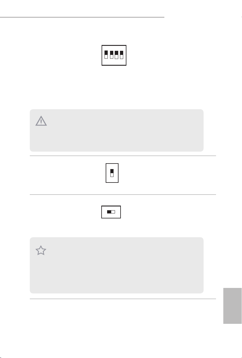
PCIe ON/OFF
Switch
(PCIE_SWITCH)
(see p.1, No. 33)
ON
1234
2: PCIE2
1: PCIE1
4: PCIE6
3: PCIE4
PCIe ON/OFF Switch allows
you to enable and disable the
corresponding PCIE x16 slots.
When one of the installed
PCIE x16 cards is out of order,
you can use PCIe ON/OFF
Switch to nd out the faulty
one just with a single click
without removing the cards.
1. Make sure that you power o the system before changing the sw itch.
2. When you turn o PCIe ON/OFF switch, your PCIE card could be burnt if it was poorly
designed. For more information about your card’s specications plea se contact the card’s
ve ndor.
3. PCIe ON/OFF switch is for debug only. If you do not want to use your PCIE card, please
remove it f rom the motherboard.
Slow Mode Switch
(SLOW MODE)
(see p.1, No. 19)
BIOS Selection
Switch
(BIOS_SEL1)
ON
OFF
If Slow Mode is on, the proces- the processor runs at lowest frequency.
BIOS Selection Switch allows
the system to boot from either
BIOS A or BIOS B.
(see p.1, No. 20)
is motherboard has two BIOS chips, a primar y BIOS (BIOS_A) and a ba ckup BIOS (BIOS_
B), which enhances the safety and stability of your system. Normally, the system w ill work
on the primary BIOS. However, if the primary BIOS is corrupted or damaged, ju st ip the
BIOS Selection Sw itch to “B”, then the backup BIOS will take over on the next system boot.
Aer that, use “Secure Backup U EFI” in the UEFI Setup Utility to duplicate a working copy
of the BIOS les to the primary BIOS to ensure normal system operation. For safety issues,
users are not able to update the backup BIOS manu ally. Users may refer to the BIOS LEDs
(BIOS_ A_LED or BIOS_B_ LED) to identify which BIOS i s currently activated.
English
29
Page 32
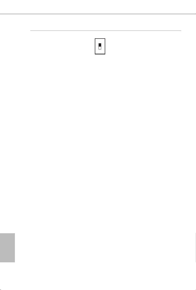
LN2 Mode Switch
(LN2MODE)
(see p.1, No. 31)
ON
OFF
e LN2 mode aids in
eliminating the cold-boot bug
issues in processors during
extreme overclocking with
Liquid Nitrogen.
English
30
Page 33

Z97 OC Formula
2.8 Dr. Debug
Dr. Debug is used to provide code information, which makes troubleshooting even
easier. Please see the diagrams below for reading the Dr. Debug codes.
Code Description
00 Please check if the CPU is installed correctly and then clear
CMOS.
0d Problem related to memory, VGA card or other devices.
Please clear CMOS, re-install the memory and VGA card,
and remove other USB, PCI devices.
01 - 54
(exce pt 0d),
5A- 60
55 e Memory could not be detected. Please re-install the
61 - 91 Chipset initialization error. Please press reset or clear
92 - 99 Problem related to PCI-E devices. Please re-install PCI-E
A0 - A7 Problem related to IDE or SATA devices. Please re-install
b0 Problem related to memory. Please re-install the CPU and
Problem related to memory. Please re-install the CPU and
memory then clear CMOS. If the problem still exists, please
install only one memory module or try using other memory
modules.
memory and CPU. If the problem still exists, please install
only one memory module or try using other memory
modules.
CMOS.
devices or try installing them in other slots. If the problem
still exists, please remove all PCI-E devices or try using
another VGA card.
IDE and SATA devices. If the problem still exists, please
clear CMOS and try removing all SATA devices.
memory. If the problem still exists, please install only one
memory module or try using other memory modules.
English
31
Page 34

b4 Problem related to USB devices. Please try removing all
USB devices.
b7 Problem related to memory. Please re-install the CPU and
memory then clear CMOS. If the problem still exists, please
install only one memory module or try using other memory
modules.
d6 e VGA could not be recognized. Please clear CMOS and
try re-installing the VGA card. If the problem still exists,
please try installing the VGA card in other slots or use other
VGA c ards.
d7 e Keyboard and mouse could not be recognized. Please
try re-installing the keyboard and mouse.
d8 Invalid Password.
FF Please check if the CPU is installed correctly and then clear
CMOS.
English
32
Page 35
Z97 OC Formula
2.9 M.2_SSD (NGFF) Module Installation Guide
The M.2, also known as the Next Generation Form Factor (NGFF), is a small size and
versatile card edge connector that aims to replace mPCIe a nd mSATA. The M.2_SSD
(NGFF) Socket 3 can accommodate either a M.2 SATA3 6.0 Gb/s module or a M.2 PCI
Express module up to Gen 2 x 2 (10 Gb/s). Please be noted that the M.2_SSD (NGFF)
Socket 3 is shared with the SATA Express connector; you can only choose either the M.2_
SSD (NGFF) Socket 3 or the SATA Express connector to use.
*e M.2_SSD (NGFF) Socket 3 supports SSD drives. Please note that the WiFi or other
non-SSD M.2 modules are not supported.
Installing the M.2_SSD (NGFF) Module
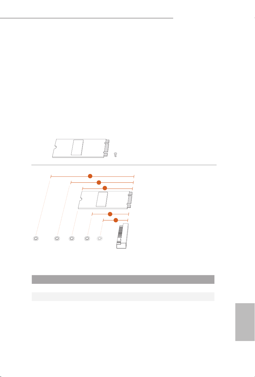
Step 1
Prepare a M.2_SSD (NGFF) module
and the screw.
5
4
3
Step 2
Depending on the PCB type and
length of your M.2_SSD (NGFF)
module, nd the corresponding nut
location to be used.
2
1
A
BCDE
No. 1 2 3 4 5
Nut Location A B C D E
PCB Length 3cm 4.2cm 6cm 8cm 11cm
Module Type Typ e2230 Type 224 2 Type22 60 Ty pe 2280 Type 22110
English
33
Page 36
Step 3
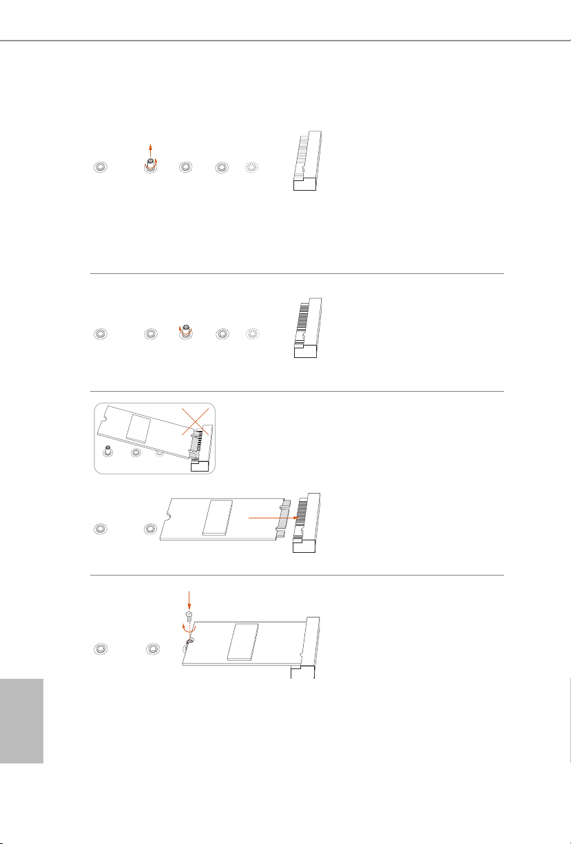
Move the stando based on the
module type and length.
A
BCDE
e stando is placed at the nut
location D by default. Skip Step 3 and
4 and go straight to Step 5 if you are
going to use the default nut.
Otherwise, release the stando by
hand.
Step 4
Peel o the yellow protective lm on
A
BCDE
the nut to be used. Hand tighten the
stando into the desired nut location
on the motherboard.
Step 5
Align and gently insert the M.2
A
BC
(NGFF) SSD module into the M.2
slot. Please be aware that the M.2
(NGFF) SSD module only ts in one
orientation.
English
34
ABCDE
Step 6
Tighten the screw with a screwdriver
to secure the module into place.
NUT1NUT2DE
Please do not overtighten the screw as
this might damage the module.
Page 37

Z97 OC Formula
M.2_SSD (NGFF) Module Support List
PCIe Interface SATA Interface
Plextor PX-G512M6e ADATA AXNS381E-128GM-B
Plextor PX-G256M6e ADATA A XNS381E-256GM-B
SanDisk SD6PP4M-128G Crucial CT120M500SSD4/120G
SanDisk SD6PP4M-256G Crucial CT240M500SSD4/240G
Samsung XP941-512G (MZHPU512HCGL) Intel SSDSCKGW080A401/80G
Kingston RBU-SM2280S3/120G
For the latest updates of M.2_SSD (NFGG) module support list, please visit our website
for details: http://www.asrock.com
35
English
Page 38
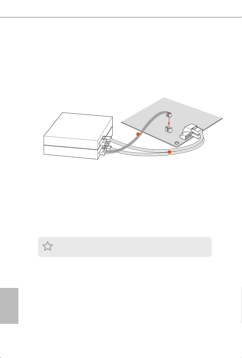
2.10 HDD Saver Cable Installation Guide
The HDD Saver Connector on this motherboard allows you to switch on and off the
connected HDDs via soware when needed. is design secures more privacy, saves more
energy, and extends the HDDs' lifespans. Please follow the steps below to install the HDD
Saver Cable.
Connection Diagram
1
HDD Saver C able
2
SATA data cable
*e diagram shown here is for reference only.
1. e diagram shown here is for reference only.Connect one end of the HDD Saver Cable
to the HDD Saver Connector (SATA_PWR_1) placed near the SATA ports. en con-placed near the SATA ports. en con-. en connect the SATA power connector(s) to your SATA HDD(s).
* e HDD Saver Connector supports up to two SATA HDDs.
English
36
2. Connect one end of the SATA data cable to a SATA port on the motherboard. en
connect the other end to your SATA HDD(s).
For the soware conguration, please refer to the section 3.2 “Formula Drive” in this u ser
manual.
Page 39
Z97 OC Formula
1 Einleitung
Vielen Dank für den Kauf unseres ASRock Z97 OC Formula, eines zuverlässigen
Motherboards, das nach ASRocks strengen Qualitätsrichtlinien gefertigt wurde. Es
liefert ausgezeichnete Leistung mit robustem Design, das ASRocks Streben nach
Qualität und Beständigkeit erfüllt.
Da die technischen Daten des Motherboards sowie die BIOS-Soware aktualisiert werden
können, kann der Inhalt dieser Dokumentation ohne Ankündigung geändert werden. Falls
diese Dokumentation irgendwelchen Änderungen unterliegt, wird die aktualisierte Version
ohne weitere Hinweise auf der ASRock-Webseite zur Verfügung gestellt. Sollten Sie technische
Hilfe in Bezug auf dieses Motherboard benötigen, erhalten Sie auf unserer Webseite spezischen
Informationen über das von Ihnen verwendete Modell. Auch nden Sie eine aktuelle Liste
unterstützter VGA-Karten und Prozessoren auf der ASRock-Webseite: ASRock-Website http://
www.asrock.com.
1.1 Lieferumfang
•ASRock Z97 OC Formula-Motherboard (ATX-Formfaktor)
•ASRock Z97 OC Formula-Schnellinstallationsanleitung
•ASRock Z97 OC Formula-Unterstützungs-CD
•1 x E/A-Abschirmung
•4 x Serial-ATA- (SATA) Datenkabel (optional)
•1 x Flexibles ASRock-SLI-Bridge-Anschlusskabel
•1 x HDD-Saver-Kabel
•1 x Schraube für M.2_SSD- (NGFF) Sockel 3
37
Deutsch
Page 40

1.2 Technische Daten
Plattform
Prozessor
Chipsatz
Speicher
Erweiterungssteckplatz
•ATX-Formfaktor
•Leiterplatte mit hochdichtem Glasgewebe
•Unterstützt Intel® Core™ i7/i5/i3/Pentium®/Celeron®-
Prozessoren (Sockel 1150) der 5., 4. und neuen 4. Generation
•Digipower-Design
•12-Leistungsphasendesign
•Unterstützt Intel® Turbo Boost 2.0-Technologie
•Unterstützt CPUs mit freiem Multiplikator der Intel® K-Serie
•Unterstützt ASRock BCLK-Übertaktung (voller Bereich)
•Intel® Z97
•Dualkanal-DDR3-Speichertechnologie
•4 x DDR3-DIMM-Steckplätze
•Unterstützt DDR3 3400+ (OC)/2933 (OC)/2800 (OC)/2400
(OC)/2133 (OC)/1866 (OC)/1600/1333/1066 nicht-ECC,
ungepuerter Speicher
•Systemspeicher, max. Kapazität: 32GB
•Unterstützt Intel® Extreme Memory Prole (XMP)1.3/1.2
•3 PCI Express 3.0 x16-Steckplätze (PCIE 1/PCIE 2/PCIE
4:einzeln bei x16 (PCIE1); dual bei x8 (PCIE1) / x8 (PCIE4);
dreifach bei x8 (PCIE1) / x4 (PCIE2) / x4 (PCIE4))
•1 PCI Express 2.0 x16-Steckplatz (PCIE6:x4-Modus)
•2 x PCI-Express 2.0-x1-Steckplätze
•Unterstützt AMD Quad CrossFireX
3-Wege-CrossFireX
TM
und CrossFireXTM
•Unterstützt NVIDIA® Quad SLI
TM
, 4-Wege-CrossFireXTM,
TM
und SLI
TM
Deutsch
38
Page 41

Z97 OC Formula
Grakkarte
Audio
•Integrierte Intel® HD Graphics-Visualisierung und VGA-
Ausgänge können nur mit Prozessoren unterstützt werden, die
GPU-integriert sind.
•Unterstützt integrierte Intel® HD Graphics-Visualisierung:
Intel® Quick Sync Video mit AVC, MVC (S3D) und MPEG2 Full HW Encode1, Intel® InTruTM 3D, Intel® Clear Video HD
Technology, Intel® InsiderTM, Intel® HD Graphics 4400/4600
•Pixel Shader 5.0, DirectX 11.1
•Max. geteilter Speicher: 1792 MB
•Unterstützt HDMI mit Maximalauösung bis 4K × 2K (4096 ×
2304) bei 24 Hz
•Unterstützt automatische Lippensynchronisierung, Deep Color
(12 Bit pro Farbe), xvYCC und HBR (High Bit Rate Audio) per
HDMI-Port(kompatibler HDMI-Monitor erforderlich)
•Unterstützt HDCP per HDMI-Port
•Unterstützt Full HD 1080p-Blu-ray-Wiedergabe (BD) über
HDMI-Port
•7.1-Kanal-HD-Audio mit Inhaltsschutz (Realtek ALC1150-
Audiocodec)
•Erstklassige Blu-ray-Audiounterstützung
•Unterstützt Überspannungsschutz (ASRock Full Spike Protec-
tion)
•Unterstützt Purity Sound
- Nichicon-Audiokappen der Fine Gold-Serie
- 115-dB-SRV-DAC mit Dierentialverstärker
- TI® NE5532 – erstklassiger Headset-Verstärker (unterstützt
Headsets mit bis zu 600 Ohm)
- Direct Drive Technology
- Abdeckung mit EMV-Abschirmung
- PCB-isolierte Abschirmung
•Unterstützt DTS Connect
TM
2
39
Deutsch
Page 42

LAN
•PCIE x1 Gigabit LAN 10/100/1000 Mb/s
•Qualcomm® Atheros® Killer
•Unterstützt Qualcomm® Atheros® Security Wake On Internet-
Technologie
•Unterstützt Wake-On-LAN
•Unterstützt Blitzschutz/Schutz gegen elektrostatische Entla-
dung (ASRock Full Spike Protection)
•Unterstützt energieezientes Ethernet 802.3az
•Unterstützt PXE
TM
E2200-Serie
Deutsch
Rückblende, E/A
Speicher
•1 x PS/2-Maus-/Tastaturanschluss
•1 x HDMI-Port
•1 x Optischer SPDIF-Ausgang
•4 x USB 2.0-Ports
•4 x USB 3.0-Ports (ASMedia ASM1074-Hub) (unterstützt
Schutz gegen elektrostatische Entladung (ASRockRundumschutz vor Spannungsspitzen))
•2 x USB 3.0-Ports (Intel® Z97) (unterstützt Schutz gegen
elektrostatische Entladung (ASRock-Rundumschutz vor
Spannungsspitzen))
•1 x RJ-45-LAN-Port mit LED (Aktivität/Verbindung-LED und
Geschwindigkeit-LED)
•1 x CMOS-löschen-Schalter
•HD-Audioanschlüsse: Hintere Lautsprecher / Zentral / Bass /
Line-in / Vorderer Lautsprecher / Mikrofon
•6 x SATA-III-6,0-Gb/s-Anschlüsse per Intel® Z97, unterstützt
RAID (RAID 0, RAID 1, RAID 5, RAID 10, Intel Rapid Storage
Technology 13 und Intel Smart Response Technology), NCQ,
AHCI, Hot-Plugging und ASRock HDD-Saver-Technologie
•2 x SATA-III-6,0-Gb/s-Anschlüsse von ASMedia ASM1061,
unterstützt NCQ, AHCI, Hot-Plugging und ASRock HDDSaver-Technologie
•1 SATA Express-Anschluss (geteilt mit SATA3_4, SATA3_5
und M.2-Sockel)
* Anzukündigende Unterstützung
•1 x M.2_SSD- (NGFF) Sockel 3, unterstützt M.2-SATA-III-6,0-
Gb/s-Modul und M.2-PCI-Express-Modul bis Gen2 x 2 (10
Gb/s)
40
Page 43

Z97 OC Formula
Anschluss
•1 x COM-Anschluss-Stileiste
•1 x TPM-Stileiste
•1 x Betrieb-LED-Stileiste
•2 x CPU-Lüeranschlüsse (1 x 4-polig, 1 x 3-polig)
•4 x Gehäuselüeranschlüsse (1 x 4-polig, 3 x 3-polig)
•1 x Netzteillüeranschluss (3-polig)
•1 x 24-poliger ATX-Netzanschluss
•2 x 8-poliger 12 V- Stromanschlüsse (Hi-Density-
Stromanschluss)
•1 x HDD-Saver-Anschluss
•1 x PCIe-Netzanschluss
•1 x Audioanschluss an Frontblende
•1 x underbolt-Erweiterungskartenanschluss
•1 x USB 2.0-Stileiste (unterstützt 2 USB 2.0-Ports)
(unterstützt Schutz gegen elektrostatische Entladung (ASRockRundumschutz vor Spannungsspitzen))
•1 x USB 3.0-Stileiste (unterstützt 2 USB 3.0-Ports)
(unterstützt Schutz gegen elektrostatische Entladung (ASRockRundumschutz vor Spannungsspitzen))
•1 x Ein-/Austaste mit LED
•1 x Reset-Taste mit LED
•V- Pro be
•Rapid OC-Tasten: Tasten +/- zur Anpassung der
•1 Menütaste
•1 x PCIe-Ein-/Ausschalter
•1 x Post Status Checker (PSC)
•1 x Langsamer-Modus-Schalter
•1 x LN2-Modus-Schalter
•1 x BIOS-Auswahlschalter
TM
: 2 x 7-teilige Spannungsmesspunkte auf Platine
Übertaktungsfrequenz
BIOS-Funktion
•2 x 64-Mb-AMI-UEFI-Legal-BIOS mit Unterstützung mehr-
sprachiger grascher Benutzerschnittstellen (1 x Haupt-BIOS
und 1 x Ausfall-BIOS)
•Unterstützt UEFI-Technologie (zuverlässige Sicherung)
•ACPI 1.1-konforme Aufweckereignisse
•SMBIOS 2.3.1-Unterstützung
•CPU, DRAM, PCH 1,05 V, PCH 1,5 V / Mehrfachspannung-
sanpassung
Deutsch
41
Page 44
Hardware
•CPU-/Gehäusetemperaturerkennung
•CPU/Gehäuse/Netzteil-Lüertachometer
•Lautloser CPU-/Gehäuselüer (automatische Anpassung der
Gehäuselüergeschwindigkeit durch CPU-Temperatur)
•CPU-/Gehäuselüer-Mehrfachgeschwindigkeitssteuerung
•Multiwärmesensor
•Spannungsüberwachung: +12 V, +5 V, +3,3 V, CPU-Eingangss-
pannung, interne CPU-Spannungen
Deutsch
Betriebssystem
Zertizierungen
* Detaillierte Produktinformationen nden Sie auf unserer Webseite: http://www.asrock.com
Bitte beachten Sie, dass mit einer Übertaktung, zu der die Anpassung von BIOS-Einstellungen,
die Anwendung der Untied Overclocking Technology oder die Nutzung von Übertaktungswerkzeugen von Drittanbietern zählen, bestimmte Risiken verbunden sind. Eine Übertaktung
kann sich auf die Stabilität Ihres Systems auswirken und sogar Komponenten und Geräte Ihres
Systems beschädigen. Sie sollte auf eigene Gefahr und eigene Kosten durchgeführt werden. Wir
übernehmen keine Verantwortung für mögliche Schäden, die durch eine Übertaktung verursacht wurden.
Aufgrund von Beschränkungen kann die Größe des tatsächlich für die Systemnutzung reservierten Speichers unter Windows®-Betriebssystemen mit 32 Bit weniger als 4 GB betragen.
Windows®-Betriebssysteme mit 64 Bit haben keine derartigen Beschränkungen. Mit ASRock
XFast RAM können Sie den Speicher einsetzen, den Windows® nicht nutzen kann.
•Microso® Windows® 10, 64 Bit / 8.1, 32 Bit / 8.1, 64 Bit / 8, 32
Bit / 8, 64 Bit / 7, 32 Bit / 7, 64 Bit
•FCC, CE, WHQL
•ErP/EuP ready (ErP/EuP ready-Netzteil erforderlich)
42
Page 45
Z97 OC Formula
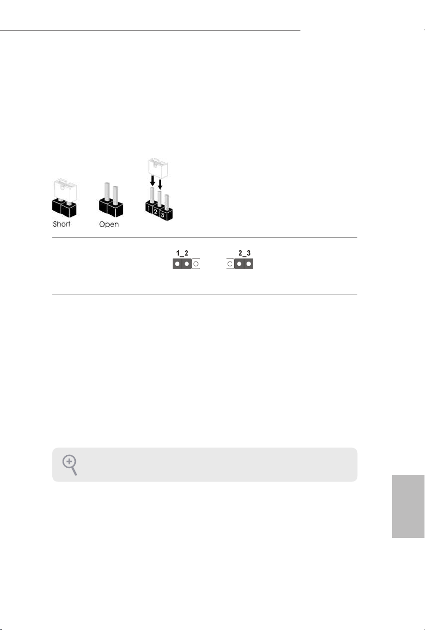
1.3 Jumpereinstellung
Die Abbildung zeigt, wie die Jumper eingestellt werden. Wenn die Jumper-Kappe auf
den Kontakten angebracht ist, ist der Jumper „kurzgeschlossen“. Wenn keine JumperKappe auf den Kontakten angebracht ist, ist der Jumper „oen“. Die Abbildung zeigt
einen 3-poligen Jumper, dessen Kontakt 1 und Kontakt 2 „kurzgeschlossen“ sind,
wenn eine Jumper-Kappe auf diesen 2 Kontakten angebracht ist.
CMOS-löschen-Jumper
(CLRMOS1)
(siehe S. 1, Nr. 42)
CLRMOS1 ermöglicht Ihnen die Löschung der Daten im CMOS. Zum Löschen
und Rücksetzen der Systemparameter auf die Standardeinrichtung schalten Sie
den Computer bitte ab und ziehen das Netzkabel aus der Steckdose. Warten Sie 15
Sekunde, schließen Sie dann Kontakt 2 und Kontakt 3 an CLRMOS1 5 Sekunden
lang mit einer Jumper-Kappe kurz. Löschen Sie den CMOS jedoch nicht direkt nach
der BIOS-Aktualisierung. Falls Sie den CMOS direkt nach Abschluss der BIOSAktualisierung löschen müssen, starten Sie das System zunächst; fahren Sie es dann
vor der CMOS-Löschung herunter. Bitte beachten Sie, dass Kennwort, Datum, Zeit
und Benutzerstandardprol nur gelöscht werden, wenn die CMOS-Batterie entfernt
wird.
CMOS löschenStandard
Der CMOS-löschen-Schalter hat dieselbe Funktion wie der CMOS-löschen-Jumper.
Deutsch
43
Page 46
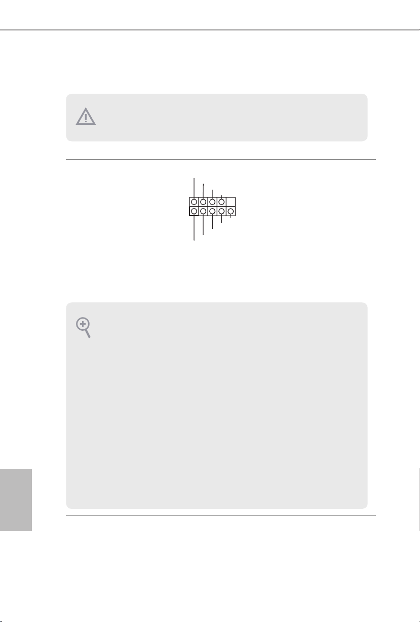
1.4 Integrierte Stiftleisten und Anschlüsse
Integrierte Stileisten und Anschlüsse sind KEINE Jumper. Bringen Sie KEINE Jumper-Kappen
an diesen Stileisten und Anschlüssen an. Durch Anbringen von Jumper-Kappen an diesen
Stileisten und Anschlüssen können Sie das Motherboard dauerha beschädigen.
Deutsch
Systemblende-Stileiste
(9-polig, PANEL1)
(siehe S. 1, Nr. 21)
PWRBTN (Ein-/Austaste):
Mit der Ein-/Austaste an der Frontblende des Gehäuses verbinden. Sie können die Abschaltung
Ihres Systems über die Ein-/Austaste kongurieren.
RESET (Reset-Taste):
Mit der Reset-Taste an der Frontblende des Gehäuses verbinden. Starten Sie den Computer
über die Reset-Taste neu, wenn er abstürzt oder sich nicht normal neu starten lässt.
PLED (Systembetriebs-LED):
Mit der Betriebsstatusanzeige an der Frontblende des Gehäuses verbinden. Die LED leuchtet,
wenn das System läu. Die LED blinkt, wenn sich das System im S1/S3-Ruhezustand bendet.
Die LED ist aus, wenn sich das System im S4-Ruhezustand bendet oder ausgeschaltet ist (S5).
HDLED (Festplattenaktivitäts-LED):
Mit der Festplattenaktivitäts-LED an der Frontblende des Gehäuses verbinden. Die LED
leuchtet, wenn die Festplatte Daten liest oder schreibt.
Das Design der Frontblende kann je nach Gehäuse variieren. Ein Frontblendenmodul besteht
hauptsächlich aus Ein-/Austaste, Reset-Taste, Betrieb-LED, Festplattenaktivität-LED, Lautsprecher etc. Stellen Sie beim Anschließen Ihres Frontblendenmoduls an diese Stileiste sicher, dass
Kabel- und Pinbelegung richtig abgestimmt sind.
1
PLED+
PLED-
HDLED-
HDLED+
PWRBTN#
GND
RESET#
GND
GND
Verbinden Sie
Netzschalter, Reset-Taste
und Systemstatusanzeige
am Gehäuse entsprechend
der nachstehenden
Pinbelegung mit dieser
Stileiste. Beachten Sie vor
Anschließen der Kabel die
positiven und negativen
Kontakte.
44
Page 47
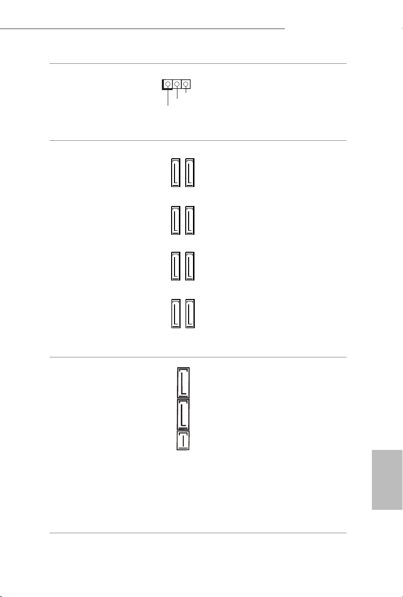
Z97 OC Formula
Betrieb-LED-Stileiste
(3-polig, PLED1)
(siehe S. 1, Nr. 26)
Serial-ATA3-Anschlüsse
(SATA3_0)
(siehe S. 1, Nr. 12)
(SATA3_1)
(siehe S. 1, Nr. 14)
(SATA3_2)
(siehe S. 1, Nr. 16)
(SATA3_3)
(siehe S. 1, Nr. 13)
(SATA3_4)
(siehe S. 1, Nr. 15)
(SATA3_5)
(siehe S. 1, Nr. 17)
(SATA3_A1)
(siehe S. 1, Nr. 10)
(SATA3_A2)
(siehe S. 1, Nr. 11)
1
SATA3_A1
SATA3_0
SATA3_1
SATA3_2
PLED+
PLED+
PLED-
SATA3_A2
SATA3_3
SATA3_4
SATA3_5
Bitte verbinden Sie die
Betrieb-LED des Gehäuses
zur
Anzeige des Systembetriebsstatus mit dieser
Stileiste.
Diese acht SATA-IIIAnschlüsse unterstützen
SATA-Datenkabel für
interne Speichergeräte mit
einer Datenübertragung
sgeschwindigkeit bis 6,0
Gb/s. SATA3_4, SATA3_5
werden mit dem SATAExpress-Anschluss geteilt.
Nutzen Sie zum
Minimieren der Startzeit
Intel® Z97-SATA-Ports
(SATA3_0) für Ihre
bootfähigen Geräte.
Serial-ATA-ExpressAnschluss
(SATAE_1)
(siehe S. 1, Nr. 18)
SATAE_1 SATA3_5 SATA3_4
Bitte verbinden Sie
entweder SATA- oder
PCIe-Speichergeräte mit
diesem Anschluss. Der
SATA Express-Anschluss
wird gemeinsam mit
SATA3_4, SATA3_5 und
dem M.2-Sockel genutzt.
* Die SATA ExpressSchnittstelle ist eine
Kombination aus
SATAE_1, SATA3_4 und
SATA3_5.
Deutsch
45
Page 48
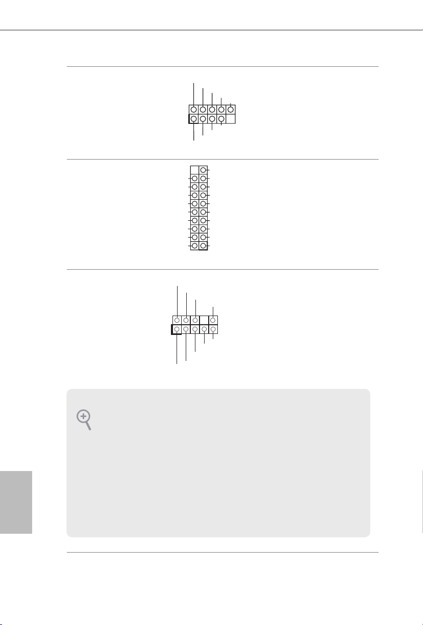
USB 2.0-Stileiste
USB_PWR
(9-polig, USB4_5)
(siehe S. 1, Nr. 35)
1
USB_PWR
P-
P+
GND
DUMMY
Neben vier USB 2.0-Ports
an der E/A-Blende bendet
sich eine Stileiste an
diesem Motherboard. Jede
GND
P+
P-
USB 2.0-Stileiste kann
zwei Ports unterstützen.
Deutsch
USB 3.0-Stileiste
(19-polig, USB3_6_7)
(siehe S. 1, Nr. 9)
Audiostileiste
(Frontblende)
(9-polig, HD_AUDIO1)
(siehe S. 1, Nr. 41)
Vbus
IntA_PA_SSRX-
IntA_PA_SSRX+
GND
IntA_PA_SSTX-
IntA_PA_SSTX+
GND
IntA_PA_D-
IntA_PA_D+
1
MIC2_L
GND
VbusVbus
IntA_PB_SSRX-
IntA_PB_SSRX+
GND
IntA_PB_SSTX-
IntA_PB_SSTX+
GND
IntA_PB_D-
IntA_PB_D+
Dummy
1
PRESENCE#
MIC_RET
J_SENSE
OUT2_R
MIC2_R
OUT_RET
OUT2_L
Neben sechs USB 3.0-Ports
an der E/A-Blende bendet
sich eine Stileiste an
diesem Motherboard. Jede
USB 3.0-Stileiste kann
zwei Ports unterstützen.
Diese Stileiste dient
dem Anschließen von
Audiogeräten an der
Frontblende.
1. High Denition Audio unterstützt Anschlusserkennung, der Draht am Gehäuse muss dazu
jedoch HDA unterstützt. Bitte befolgen Sie zum Installieren Ihres Systems die Anweisungen
in unserer Anleitung und der Anleitung zum Gehäuse.
2. Bei Nutzung eines AC’97-Audiopanels dieses bitte anhand folgender Schritte an der Audiostileiste der Frontblende installieren:
A. Mic_IN (Mikrofon) mit MIC2_L verbinden.
B. Audio_R (RIN) mit OUT2_R und Audio_L (LIN) mit OUT2_L verbinden.
C. Erde (GND) mit Erde (GND) verbinden.
D. MIC_RET und OUT_RET sind nur für das HD-Audiopanel vorgesehen. Sie müssen sie
nicht für das AC’97-Audiopanel verbinden.
E. Rufen Sie zum Aktivieren des vorderen Mikrofons das „Vorderes Mikrofon“-Register in der
Realtek-Systemsteuerung auf und passen „Aufnahmelautstärke“ an.
46
Page 49
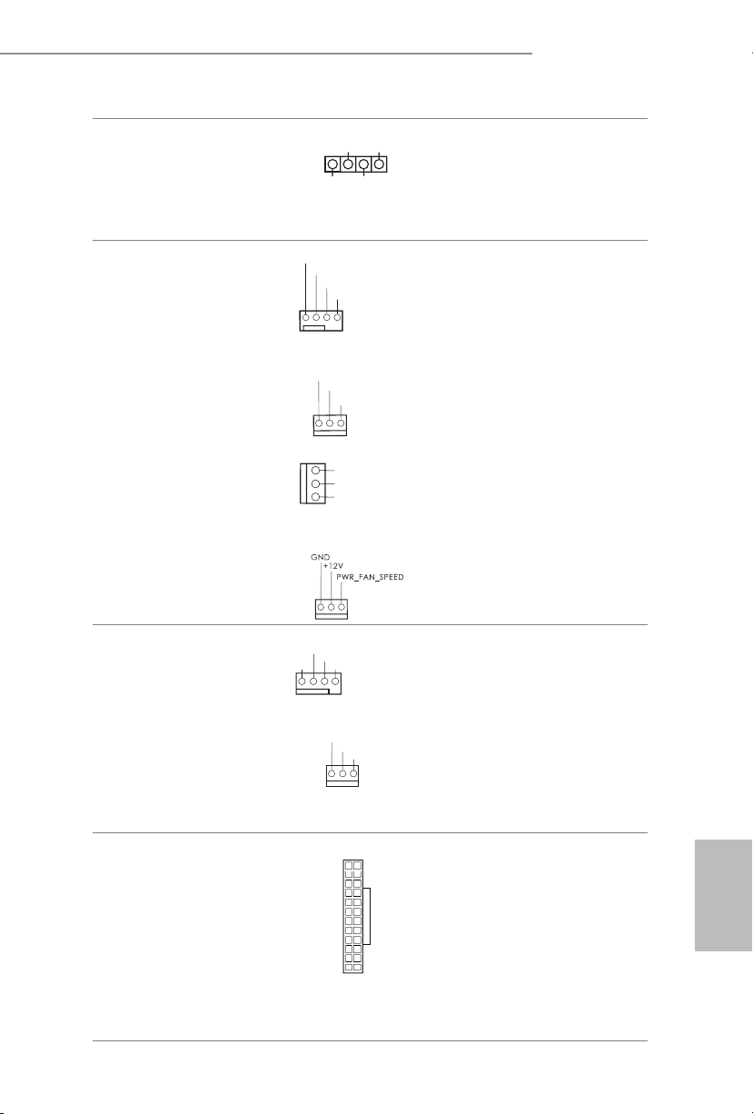
Gehäuselautsprecher-
GND
stileiste
(4-polig, SPEAKER1)
(siehe S. 1, Nr. 22)
Gehäuse- und Netzteillüeranschlüsse
(4-polig, CHA_FAN1)
(siehe S. 1, Nr. 37)
(3-polig, CHA_FAN2)
(siehe S. 1, Nr. 32)
DUMMY
1
GND
+12V
CHA_FAN_SPEED
+5V
FAN_VOLTAGE
SPEAKER
DUMMY
FAN_SPEED_CONTROL
CHA_FAN_SPEED
Z97 OC Formula
Bitte verbinden Sie den
Gehäuselautsprecher mit
dieser Stileiste.
Bitte verbinden Sie die
Lüerkabel mit den
Lüeranschlüssen; der
schwarze Draht gehört
zum Erdungskontakt.
(3-polig, CHA_FAN3)
(siehe S. 1, Nr. 43)
(3-polig, CHA_FAN4)
(siehe S. 1, Nr. 44)
(3-polig, PWR_FAN1)
(siehe S. 1, Nr. 36)
CPU-Lüeranschlüsse
(4-polig, CPU_FAN1)
(siehe S. 1, Nr. 3)
(3-polig, CPU_FAN2)
(siehe S. 1, Nr. 4)
ATX-Netzanschluss
(24-polig, ATXPWR1)
(siehe S. 1, Nr. 8)
+12V
GND
CPU_FAN_SPEED
GND
FAN_VOLTAGE
CHA_FAN_SPEED
FAN_SPEED_CONTROL
CPU_FAN_SPEED
FAN_VOLTAGE
GND
12
24
1
13
Dieses Motherboard bietet
einen 4-poligen CPULüeranschluss (lautloser
Lüer). Falls Sie einen
3-poligen CPU-Lüer
anschließen möchten,
verbinden Sie ihn bitte mit
Kontakt 1 bis 3.
Dieses Motherboard
bietet einen 24-poligen
ATX-Netzanschluss.
Bitte schließen Sie es zur
Nutzung eines 20-poligen
ATX-Netzteils entlang
Kontakt 1 und Kontakt 13
an.
Deutsch
47
Page 50
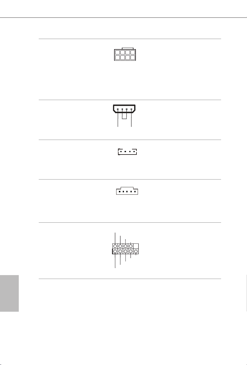
ATX 12 V-Stromanschlüsse
8
5
(8-polig, ATX12V1)
(siehe S. 1, Nr. 2)
(8-polig, ATX12V3)
(siehe S. 1, Nr. 1)
Dieses Motherboard bietet
zwei 8-polige ATX-12-V-
4
1
Netzanschlüsse. Bitte
schließen Sie es zur Nutzung eines 4-poligen ATXNetzteils entlang Kontakt 1
und Kontakt 5 an.
Deutsch
PCIe-Netzanschluss
(4-polig, PCIE_PWR1)
(siehe S. 1, Nr. 40)
HDD-Saver-Anschluss
(4-polig, SATA_PWR_1)
(siehe S. 1, Nr. 29)
underboltErweiterungskartenanschluss
(5-polig, TB1)
(siehe S. 1, Nr. 34)
Serieller-Port-Stileiste
(9-polig, COM1)
(siehe S. 1, Nr. 39)
GND
+12V DETECT
1
RRXD1
DDTR#1
DDSR#1
1
GND
TTXD1
DDCD#1
CCTS#1
RRI#1
RRTS#1
Bitte verbinden Sie ein 4-poliges
Molex-Netzkabel mit diesem
Anschluss, wenn mehr als drei
Grakkarten installiert sind.
Bitte verbinden Sie zum Verwalten
des Energiestatus der Festplatte
das HDD-Saver-Kabel mit diesem
Anschluss.
Bitte schließen Sie per GPIO-
1
Kabel eine underbolt™Erweiterungskarte (AIC) an
diesen Anschluss an.
Diese COM1-Stileiste
unterstützt ein Modul für
serielle Ports.
48
Page 51
Z97 OC Formula
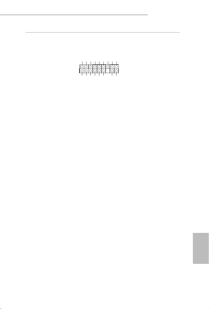
TPM-Stileiste
(17-polig, TPMS1)
(siehe S. 1, Nr. 38)
Dieser Anschluss
unterstützt das Trusted
Platform Module- (TPM)
SMB _CLK_ MAIN
GND
SMB _DATA _MAIN
LAD 2
GND
LAD 1
System, das Schlüssel,
S_P WRDWN #
SER IRQ#
GND
digitale Zertikate,
1
+3V
LAD 3
FRA ME
PCI CLK
LAD 0
PCI RST#
Kennwörter und Daten
sicher auewahren kann.
GND
Ein TPM-System hil
+3V SB
zudem bei der Stärkung
der Netzwerksicherheit,
schützt digitale Identitäten
und gewährleistet die
Plattformintegrität.
49
Deutsch
Page 52
TM
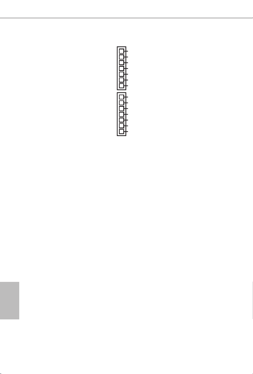
V-P rob e
(VOL_CON1
(7-polig), VOL_
CON2 (7-polig))
(siehe S. 1, Nr. 7)
IOD
IGPU
SA
Cache
IOA
VCORE0
GND
ICC
DMI
1.5PCH
1.05PCH
VDimm
Input Volt
GND
Benutzer können Spannung integrierter Komponenten messen.
IOD:
CPU-Digital-I/O-Spannung
IGPU:
GT-Spannung
SA:
CPU-Systemagent-Spannung
Cache:
CPU-Cache-Spannung
IOA :
CPU-Analog-I/
O-Spannung
Deutsch
50
VCORE0:
CPU-CORE0-Spannung
ICC:
ICC-Spannung
DMI:
DMI-Spannung
1,5VPCH:
PCH-1,5-V-Spannung
1,05PCH:
PCH-1,05-V-Spannung
VDimm:
DRAM-Spannung
Eingangsspannung:
CPU-Eingangsspannung
Page 53
Z97 OC Formula
+
-
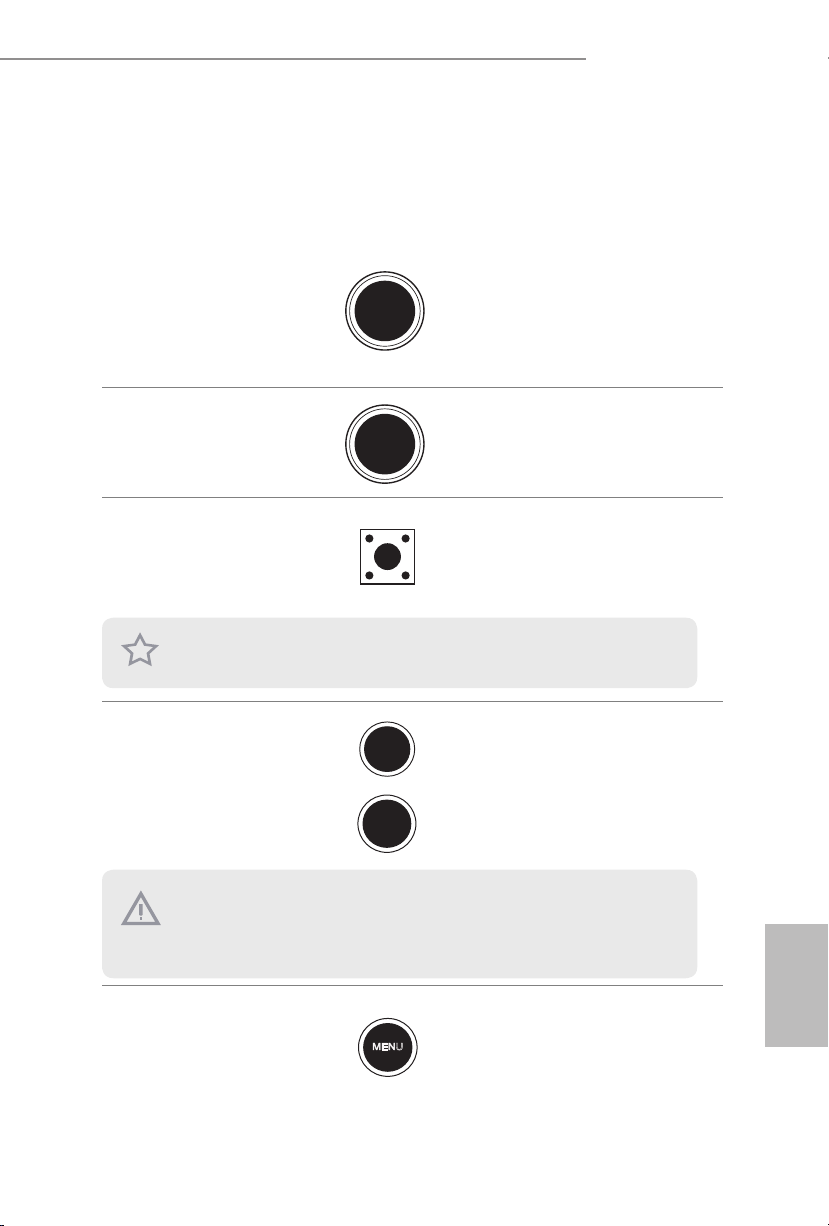
1.5 Intelligente Schalter
Das Motherboard verfügt über zehn spezielle Tasten: Ein/Aus, Reset, CMOS löschen,
Rapid OC-Tasten, Menü, PCIe-Ein/Aus, Reduzierte Geschwindigkeit, BIOS-Auswahl,
LN2-Modus.
Ein-/Ausschalter
(PWR)
(siehe S. 1, Nr. 24)
Reset-Schalter
(RST)
(siehe S. 1, Nr. 25)
CMOS-löschen-Schalter
(CLRCBTN1)
(siehe Seite 4, Nr. 4)
Diese Funktion ist nur verfügbar, wenn Sie Ihren Computer abschalten und die Stromversorgung unterbrechen.
Schnellübertaktungstasten +/(MINUS:siehe S. 1,
Nr. 27)
(PLUS:siehe S. 1, Nr.
28)
Power
Reset
Mit dem Ein-/Ausschalter
kann der Benutzer das
System schnell ein-/
abschalten.
Der Reset-Taste ermöglicht
das schnelle Rücksetzen des
Systems.
Mit dem CMOS-löschenSchalter können Benutzer
die CMOS-Werte schnell
löschen.
Mit den Rapid OC-Tasten
(+/-) passen Sie Übertaktungsfrequenzen schnell und
einfach per Rapid OC an.
Dieses Übertaktungsverhalten hängt von der Systemkonguration, wie Speicherfähigkeit,
Wärmelösung etc. ab. Eine Übertaktung kann sich auf Ihre Systemstabilität auswirken und
sogar Schäden an Komponenten und Geräten verursachen. Wir übernehmen keine Verantwortung für mögliche Schäden, die durch eine Übertaktung verursacht wurden.
Menütaste
(MENU:siehe S. 1, Nr.
30)
MENU
Schalten Sie bei der Schnellübertaktung mit der MENU-Taste zwischen verschiedenen Übertaktungsoptionen wie Basistakt, Verhältnis
und Cache-Verhältnis um.
Deutsch
51
Page 54
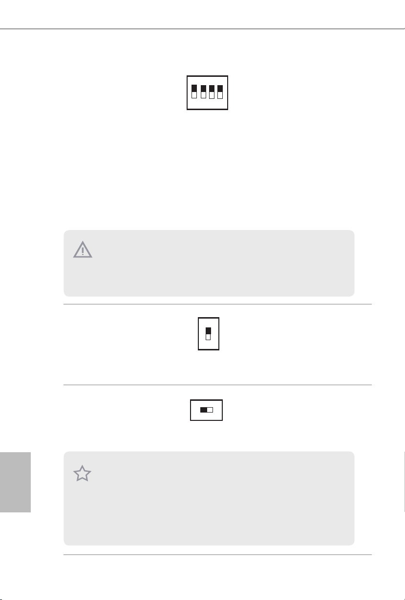
PCIe-Ein-/
AB
Ausschalter(PCIE_
SWITCH)
(siehe S. 1, Nr. 33)
ON
1234
2: PCIE2
1: PCIE1
4: PCIE6
3: PCIE4
PCIe-Ein-/Ausschalter
ermöglicht Ihnen die De-/
Aktivierung der entsprechenden PCIE-x16Steckplätze. Wenn eine der
installierten PCIE-x16Karte nicht funktioniert,
können Sie mit dem PCIeEin-/Ausschalter die
defekte Karte mit einem
einzigen Klick ausndig
machen, ohne die Karten
entfernen zu müssen.
1. Stellen Sie vor Umschalten des Schalter sicher, dass das System abgeschaltet ist.
2. Wenn Sie den PCIe-Ein-/Ausschalter ausschalten, kann Ihre PCIE-Karte Schaden nehmen,
falls sie schlecht konzipiert ist. Weitere Informationen zu den technischen Daten Ihrer Karte
erhalten Sie beim entsprechenden Händler.
3. Der PCIe-Ein-/Ausschalter dient nur der Fehlerbehebung. Falls Sie Ihre PCIE-Karte nicht
nutzen möchten, entfernen Sie sie bitte vom Motherboard.
Deutsch
52
Langsamer-ModusSchalter
(SLOWMODE)
(siehe S. 1, Nr. 19)
BIOS-Auswahlschalter
(BIOS_SEL1)
(siehe S. 1, Nr. 20)
Dieses Motherboard verfügt über zwei BIOS-Chips, ein primäres BIOS (BIOS_A) und ein
Ausfall-BIOS (BIOS_B), die Sicherheit und Stabilität Ihres Systems steigern. Normalerweise
läu das System über das primäre BIOS. Falls das primäre BIOS jedoch beschädigt ist oder ausfällt, stellen Sie den BIOS-Auswahlschalter einfach auf „B“ um; dann übernimmt das AusfallBIOS beim nächsten Systemstart. Duplizieren Sie dann mit „Secure Backup UEFI“ im UEFIEinrichtungsprogramm zur Gewährleistung eines normalen Systembetriebs eine Arbeitskopie
der BIOS-Dateien am primären BIOS. Aus Sicherheitsgründen können Benutzer das AusfallBIOS nicht manuell aktualisieren. Sie können das aktuell aktivierte BIOS anhand der BIOSLEDs (BIOS_A_LED oder BIOS_B_LED) bestimmen.
ON
OFF
Wenn der langsame Modus
eingeschaltet ist, arbeitet
der Prozessor bei niedrigster Frequenz.
Der BIOS-Auswahlschalter
ermöglicht dem System,
von BIOS A oder BIOS B
zu starten.
Page 55
Z97 OC Formula
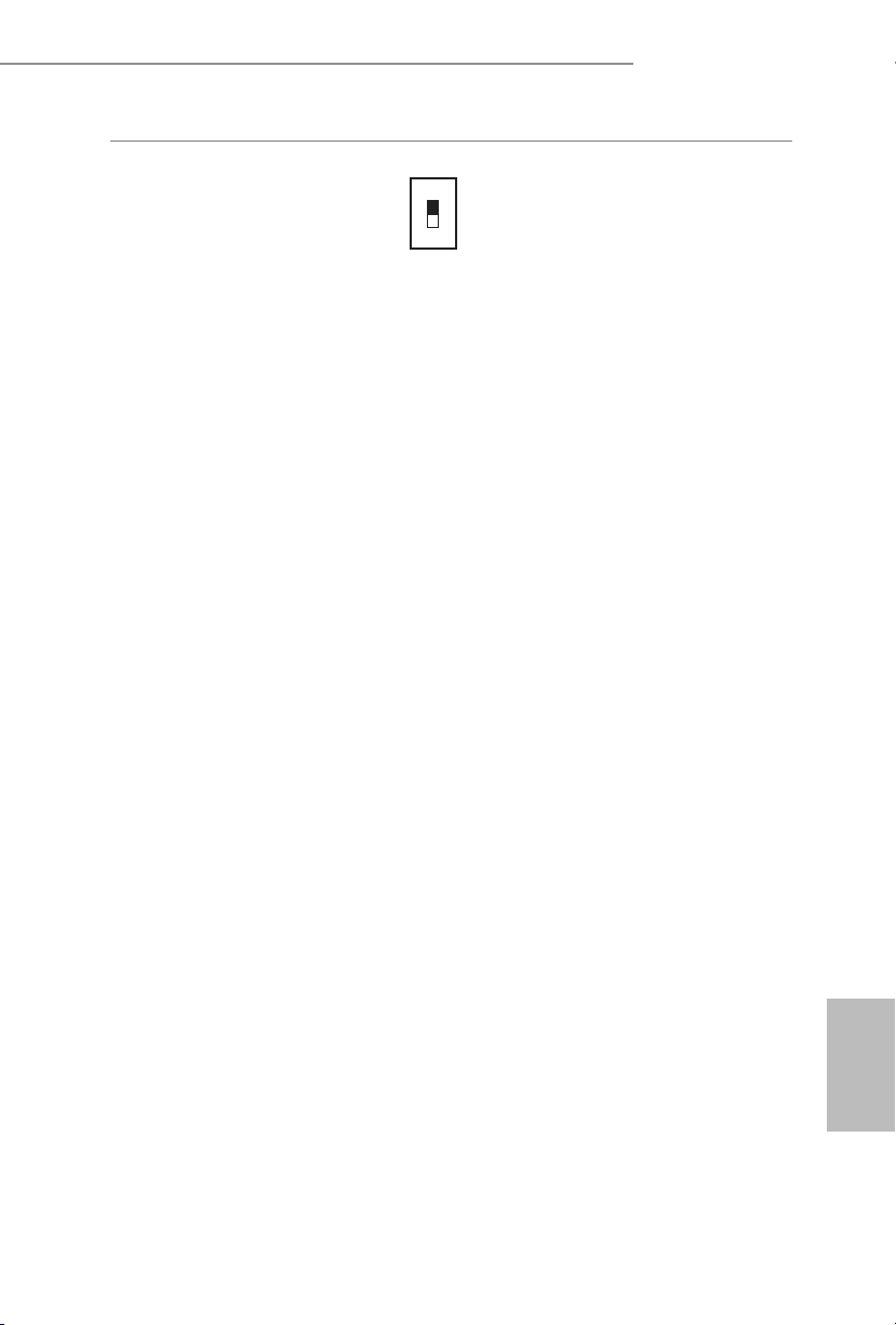
LN2-Modusschalter
(LN2MODE)
(siehe S. 1, Nr. 31)
ON
OFF
Der LN2-Modus hil
bei der Eliminierung
von Kaltstartfehlern in
Prozessoren bei extremer
Übertaktung mit üssigem
Sticksto.
53
Deutsch
Page 56
1 Introduction
Nous vous remercions d’avoir acheté cette carte mère ASRock Z97 OC Formula, une
carte mère able fabriquée conformément au contrôle de qualité rigoureux et constant
appliqué par ASRock. Fidèle à son engagement de qualité et de durabilité, ASRock
vous garantit une carte mère de conception robuste aux performances élevées.
Les spécications de la carte mère et du logiciel BIOS pouvant être mises à jour, le contenu de ce
document est soumis à modication sans préavis. En cas de modications du présent document,
la version mise à jour sera disponible sur le site Internet ASRock sans notication préalable.
Si vous avez besoin d’une assistance technique pour votre carte mère, veuillez visiter notre site
Internet pour plus de détails sur le modèle que vous utilisez. La liste la plus récente des cartes
VGA et des processeurs pris en charge est également disponible sur le site Internet de ASRock.
Site Internet ASRock http://www.asrock.com.
1.1 Contenu de l’emballage
•Carte mère ASRock Z97 OC Formula (facteur de forme ATX)
•Guide d’installation rapide ASRock Z97 OC Formula
•CD d’assistance ASRock Z97 OC Formula
•1 x protection E/S
•4 x câbles de données Serial ATA (SATA) (Optionnel)
•1 x câble connecteur exible pont SLI ASRock
•1 x câble de sauvegarde HDD
•1 x vis pour M.2_SSD (NGFF) Prise 3
Français
54
Page 57

1.2 Spécications
Z97 OC Formula
Plateforme
Processeur
Chipset
Mémoire
•Facteur de forme ATX
•PCB en tissu de verre haute densité
•Prend en charge les processeurs Intel® Core™ i7/i5/
i3/Pentium®/Celeron® Processors 4e, nouvelle 4e et 5e
génération (socket 1150)
•Conception Digi Power
•Alimentation à 12 phases
•Prend en charge la technologie Intel® Turbo Boost 2.0
•Prend en charge les processeurs débloqués de la série K
Intel®
•Prend en charge l’overclocking ASRock BCLK Full-range
•Intel® Z97
•Technologie mémoire double canal DDR3
•4 x fentes DIMM DDR3
•Prend en charge les mémoires sans tampon non ECC
DDR3 3400+(OC)/2933(OC)/2800(OC)/2400(OC)/2133
(OC)/1866(OC)/1600/1333/1066
•Capacité max. de la mémoire système : 32GB
•Prend en charge Intel® Extreme Memory Prole
(XMP)1.3/1.2
Fente
d’expansion
•3 x fentes PCI Express 3.0 x 16 (PCIE1/PCIE2/
PCIE4:simple en mode x16 (PCIE1) ; double en mode
x8 (PCIE1) / x8 (PCIE4) ; triple en mode x8 (PCIE1) / x4
(PCIE2) / x4 (PCIE4))
•1 x fente PCI Express 2.0 x16 (PCIE6:mode x4)
•2 x fentes PCI Express 2.0 x1
•Prend en charge AMD Quad CrossFireX
CrossFireXTM, 3-Way CrossFireX
•Prend en charge NVIDIA® Quad SLI
TM
TM
, 4-Way
and CrossFireXTM
TM
TM
et SLI
Français
55
Page 58

Graphiques
•La technologie Intel® HD Graphics Built-in Visuals et les
sorties VGA sont uniquement prises en charge par les
processeurs intégrant un contrôleur graphique.
•Prend en charge la technologie Intel® HD Graphics Built-in
Visuals : Intel® Quick Sync Video avec AVC, MVC (S3D) et
MPEG-2 Full HW Encode1, Intel® InTruTM 3D, technologie
Intel® Clear Video HD, Intel® InsiderTM, Intel® HD Graphics
4400/4600
•Pixel Shader 5.0, DirectX 11.1
•Mémoire partagée max. 1792Mo
•Prend en charge la technologie HDMI avec résolution
maximale de 4K × 2K (4096x2304) @ 24Hz
•Prend en charge les technologies Auto Lip Sync, Deep
Color (12bpc), xvYCC et HBR (High Bit Rate Audio) avec
HDMI(un écran compatible HDMI est requis)
•Prend en HDCP via port HDMI
•Prend en charge la lecture Blu-ray (BD) Full HD 1080p via
HDMI
Français
56
Audio
•Audio 7.1 CH HD avec protection du contenu (codec audio
Realtek ALC1150)
•Compatible audio Blu-ray Premium
•Protection contre les surtensions (Protection complète
contre les pics ASRock)
•Prend en charge Purity Sound
- Couvercles audio série en or n Nichicon
- 115dB SNR DAC avec amplicateur diérentiel
- Amplicateur de casque TI® NE5532 Premium (prend en
charge les casques jusqu’à 600 Ohms)
- Technologie Direct Drive
- Capot à blindage EMI
- Blindage isolant PCB
•Prend en charge DTS Connect
TM
2
Page 59
Z97 OC Formula
Réseau
Connectique
du panneau
arrière
•PCIE x1 Gigabit LAN 10/100/1000 Mo/s
•Qualcomm® Atheros® Killer
•Prend en charge la technologie Qualcomm® Atheros® Secu-
rity Wake On sur Internet
•Prend en charge la fonction Wake-On-LAN
•Protection contre les orages/décharges électrostatiques
(Protection complète contre les pics ASRock)
•Prend en charge la fonction d’économie d’énergie Ethernet
802.3az
•Prend en charge PXE
•1 x port souris/clavier PS/2
•1 x port HDMI
•1 x port sortie optique SPDIF
•4 x ports USB 2.0
•4 x ports USB 3.0 (ASMedia ASM1074) (Protection contre
les décharges électrostatiques (Protection complète contre
les pics ASRock))
•2 x ports USB 3.0 (Intel® Z97) (Protection contre les
décharges électrostatiques (Protection complète contre les
pics ASRock))
•1 x port RJ-45 LAN avec LED (LED ACT/LIEN et LED
VITESSE)
•1 x bouton Clear CMOS
•Connecteurs jack audio HD : Haut-parleur arrière / central
/ basses / entrée ligne / haut-parleur avant / microphone
TM
série E2200
57
Français
Page 60

Stockage
•6 x connecteurs SATA3 6,0 Gb/s par Intel® Z97, compatibles
RAID (RAID 0, RAID 1, RAID 5, RAID 10, technologies
Intel Rapid Storage 13 et Intel Smart Response), NCQ,
AHCI, «Hot Plug» et sauvegarde HDD ASRock
•2 x connecteurs SATA3 6,0 Go/s ASMedia ASM1061,
compatibles avec les fonctions NCQ, AHCI, «Hot Plug» et
sauvegarde HDD ASRock
•1 x connecteur SATA Express (partagé avec SATA3_4,
SATA3_5 et socket M.2_SSD)
* Prise en charge dévoilée prochainement
•1 x M.2_SSD (NGFF) socket 3, prend en charge les modules
M.2 SATA3 6,0 Gb/s et M.2 PCI Express jusqu’à Gen2 x2 (10
Gb/s)
Français
58
Page 61

Z97 OC Formula
Connectique
•1 x embase pour port COM
•1 x embase TPM
•1 x embase LED d’alimentation
•2 x connecteurs pour ventilateur de processeur (1 x 4
broches, 1 x 3 broches)
•4 x connecteurs pour ventilateur de châssis (1 x 4 broches,
3 x 3 broches)
•1 x connecteur pour ventilateur d’alimentation (3 broches)
•1 x connecteur d’alimentation ATX 24 broches
•2 x connecteur d’alimentation 12V 8 broches (connecteurs
d’alimentation haute densité)
•1 x connecteur de sauvegarde HDD
•1 x connecteur d’alimentation PCIe
•1 x connecteur audio panneau frontal
•1 x connecteur underbolt AIC
•1 x embase USB 2.0 (2 ports USB 2.0 pris en charge)
(Protection contre les décharges électrostatiques (Protection
complète contre les pics ASRock))
•1 x embase USB 3.0 (2 ports USB 3.0 pris en charge)
(Protection contre les décharges électrostatiques (Protection
complète contre les pics ASRock))
•1 x bouton de mise en marche avec témoin LED
•1 x bouton de réinitialisation avec témoin LED
•V- Pro be
•Boutons pour OC rapide: Boutons +/- pour régler la
•1 x menu bouton
•1 x interrupteur marche/arrêt PCIe
•1 x Post Status Checker (PSC)
•1 x interrupteur mode lent
•1 x interrupteur mode LN2
•1 x bouton de sélection du BIOS
TM
: 2 x 7 sets de points de mesure de tension
embarqués
fréquence OC
Français
59
Page 62
Caractéristiques du
BIOS
•2 x BIOS UEFI AMI 64Mo légaux avec prise en charge
interface graphique multilingue (1 x BIOS principal et 1 x
BIOS de sauvegarde)
•Prend en charge la technologie de sauvegarde sécurisée
UEFI
•Compatible ACPI 1.1 Wake Up Events
•Prend en charge SMBIOS 2.3.1
•Réglage de la tension CPU, DRAM, PCH 1,05V, PCH 1,5V
Français
Surveillance
•Détection de la température du processeur/châssis
•Tachéomètre processeur/châssis/ventilateur d’alimentation
•Ventilateur silencieux processeur/châssis (réglage au-
tomatique de la vitesse du ventilateur du châssis d’après la
température du processeur)
•Contrôle simultané des vitesses des ventilateurs processeur/
châssis
•Capteur multi-thermique
•Surveillance de la tension d’alimentation : +12V, +5V,
+3,3V, tension d’entrée du processeur, tensions internes du
processeur
Système
d’exploitation
Certications
•Microso® Windows® 10 64 bits / 8.1 32 bits / 8.1 64 bits / 8
32 bits / 8 64 bits / 7 32 bits / 7 64 bits
•FCC, CE, WHQL
•ErP/EuP Ready (alimentation ErP/EuP ready requise)
* pour des informations détaillées de nos produits, veuillez visiter notre site: http://www.asrock.com
Il est important de signaler que l’overcloking présente certains risques, incluant des modications du BIOS, l’application d’une technologie d’overclocking déliée et l’utilisation d’outils
d’overclocking développés par des tiers. La stabilité de votre système peut être aectée par ces
pratiques, voire provoquer des dommages aux composants et aux périphériques du système.
L’overclocking se fait à vos risques et périls. Nous ne pourrons en aucun cas être tenus pour
responsables des dommages éventuels provoqués par l’overclocking.
60
En raison de limitations dues au système d’exploitation, la capacité de mémoire utilisée sous
Windows® 32-bit peut être inférieure à 4 Go. Cette limitation ne concerne pas les systèmes
d’exploitation Windows® 64-bit. Vous pouvez utiliser ASRock XFast RAM pour utiliser la
mémoire dont Windows® ne peut se servir.
Page 63
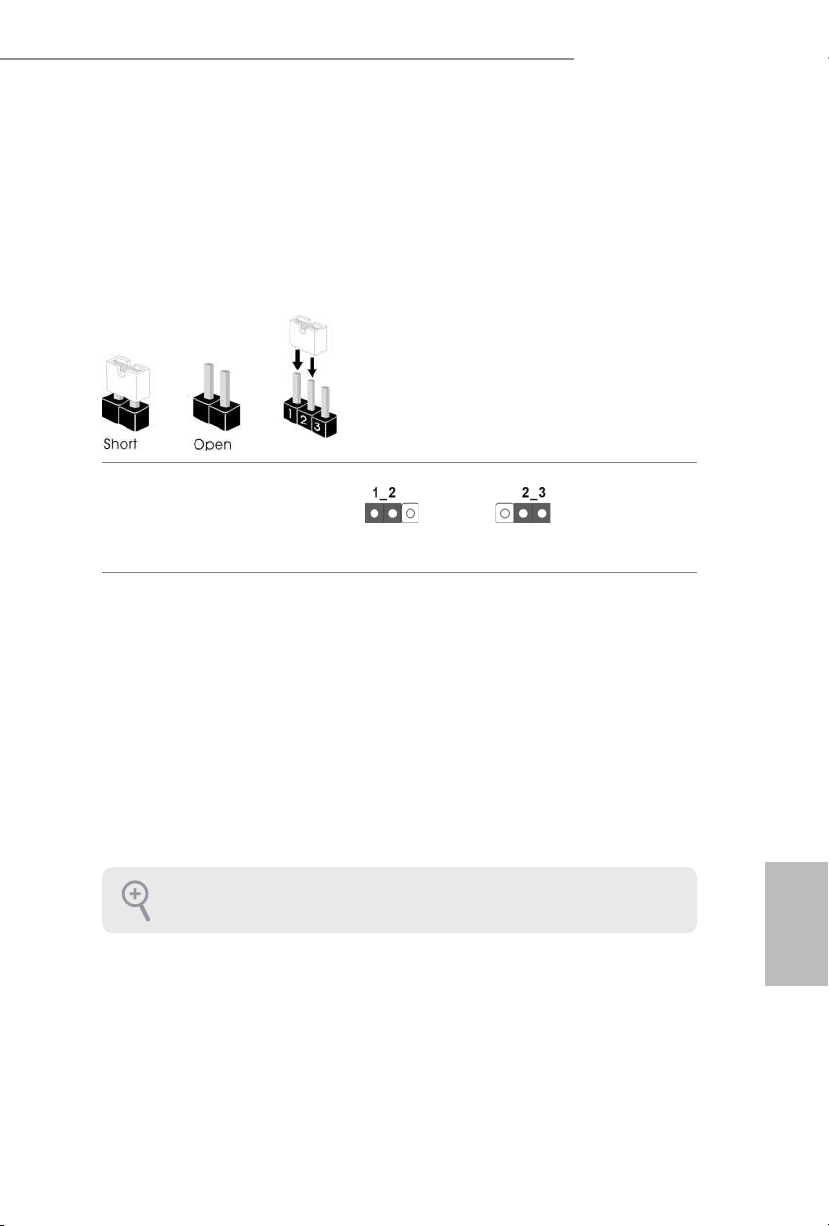
Z97 OC Formula
1.3 Conguration des cavaliers (jumpers)
L’illustration ci-dessous vous renseigne sur la conguration des cavaliers (jumpers).
Lorsque le capuchon du cavalier est installé sur les broches, le cavalier est «courtcircuité». Si le capuchon du cavalier n’est pas installé sur les broches, le cavalier est
«ouvert». L’illustration représente un cavalier à 3 broches dont les broches 1 et 2 sont
«court-circuitées» si un capuchon de cavalier est posé sur ces 2 broches.
Cavalier Clear CMOS
(CLRMOS1)
(voir p.1, No. 42)
CLRMOS1 vous permet d’eacer les donnés de la CMOS. Pour eacer les paramètres
du système et rétablir les valeurs par défaut, veuillez éteindre votre ordinateur
et débrancher son cordon d’alimentation. Patientez 15 secondes, puis utilisez un
capuchon de cavalier pour court-circuiter la broche 2 et la broche 3 sur CLRMOS1
pendant 5 secondes. Toutefois, n’eacez pas la CMOS immédiatement après avoir
mis à jour le BIOS. Si vous avez besoin d’eacer les données CMOS après une mise à
jour du BIOS, vous devez tout d’abord redémarrer le système, puis l’éteindre avant de
procéder à l’eacement de la CMOS. Veuillez noter que les paramètres mot de passe,
date, heure et prol de l’utilisateur seront uniquement eacés en cas de retrait de la
pile de la CMOS.
Fonction Clear CMOSPar défaut
Le bouton Clear CMOS possède la même fonction que le cavalier (jumper) Clear CMOS.
Français
61
Page 64
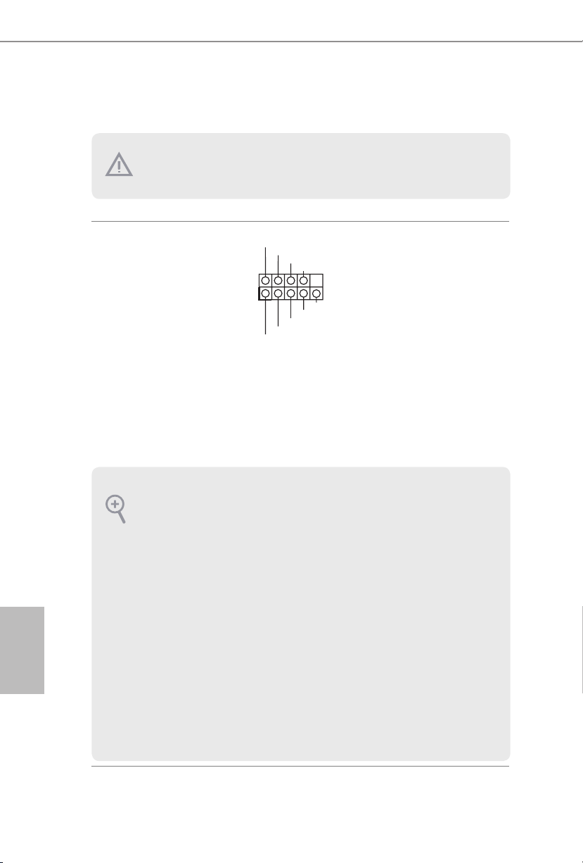
1.4 Embases et connecteurs de la carte mère
Les embases et connecteurs situés sur la carte NE SONT PAS des cavaliers. Ne placez JAMAIS
de capuchons de cavaliers sur ces embases ou connecteurs. Placer un capuchon de cavalier sur
ces embases ou connecteurs endommagera irrémédiablement votre carte mère.
Français
Embase du panneau
système
(PANNEAU1 à 9
broches)
(voir p.1, No. 21)
PWRBTN (bouton d’alimentation):
pour brancher le bouton d’alimentation du panneau frontal du châssis. Vous pouvez congurer
la façon dont votre système doit s’arrêter à l’aide du bouton de mise en marche.
RESET (bouton de réinitiélisation):
pour brancher le bouton de réinitialisation du panneau frontal du châssis. Appuyez sur le bouton de réinitialisation pour redémarrer l’ordinateur en cas de plantage ou de dysfonctionnement
au démarrage.
PLED (LED d’alimentation du système) :
pour brancher le témoin d’état de l’alimentation du panneau frontal du châssis. Le LED est allumé lorsque le système fonctionne. Le LED clignote lorsque le système se trouve en mode veille
S1/S3. Le LED est éteint lorsque le système se trouve en mode veille S4 ou hors tension (S5).
HDLED (LED d’activité du disque dur) :
pour brancher le témoin LED d’activité du disque dur du panneau frontal du châssis. Le LED
est allumé lorsque le disque dur lit ou écrit des données.
La conception du panneau frontal peut varier en fonction du châssis. Un module de panneau
frontal est principalement composé d’un bouton de mise en marche, bouton de réinitialisation,
LED d’alimentation, LED d’activité du disque dur, haut-parleur etc. Lorsque vous reliez le
module du panneau frontal de votre châssis sur cette embase, veillez à parfaitement faire correspondre les ls et les broches.
1
PLED+
PLED-
HDLED-
HDLED+
PWRBTN#
GND
RESET#
GND
GND
Branchez le bouton
de mise en marche, le
bouton de réinitialisation
et le témoin d’état du
système présents sur
le châssis sur cette
embase en respectant
la conguration des
broches illustrée cidessous. Repérez les
broches positive et
négative avant de
brancher les câbles.
62
Page 65
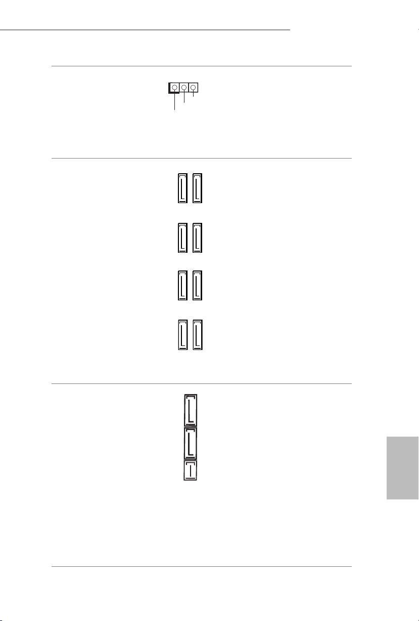
Z97 OC Formula
Embase LED
d’alimentation
(PLED1 à 3 broches)
(voir p.1, No. 26)
Connecteurs Serial ATA3
(SATA3_0)
(voir p.1, No. 12)
(SATA3_1)
(voir p.1, No. 14)
(SATA3_2)
(voir p.1, No. 16)
(SATA3_3)
(voir p.1, No. 13)
(SATA3_4)
(voir p.1, No. 15)
(SATA3_5)
(voir p.1, No. 17)
(SATA3_A1)
(voir p.1, No. 10)
(SATA3_A2)
(voir p.1, No. 11)
1
SATA3_A1
SATA3_0
SATA3_1
SATA3_2
PLED+
PLED+
PLED-
SATA3_A2
SATA3_3
SATA3_4
SATA3_5
Veuillez brancher le
LED d’alimentation
du châssis sur cette
embase
pour indiquer
l’état d’alimentation du
système.
Ces huit connecteurs
SATA3 sont compatibles
avec les câbles de
données SATA pour les
appareils de stockage
internes avec un taux
de transfert maximal
de 6,0 Go/s. SATA3_4,
SATA3_5 sont partagés
avec le connecteur SATA
Express.
Pour minimiser le temps
au démarrage, utilisez les
ports Intel® Z97 SATA
(SATA3_0) pour vos
appareils démarrables.
Connecteur série ATA
Express
(SATAE_1)
(voir p.1, No. 18)
SATAE_1 SATA3_5 SATA3_4
Veuillez connecter
des périphériques de
stockage SATA ou
PCIe à ce connecteur.
Le connecteur SATA
Express est partagé avec
SATA3_4, SATA3_5 et
socket M.2
*L’interface SATA
Express est une
combinaison de
SATAE_1, SATA3_4 et
SATA3_5.
Français
63
Page 66
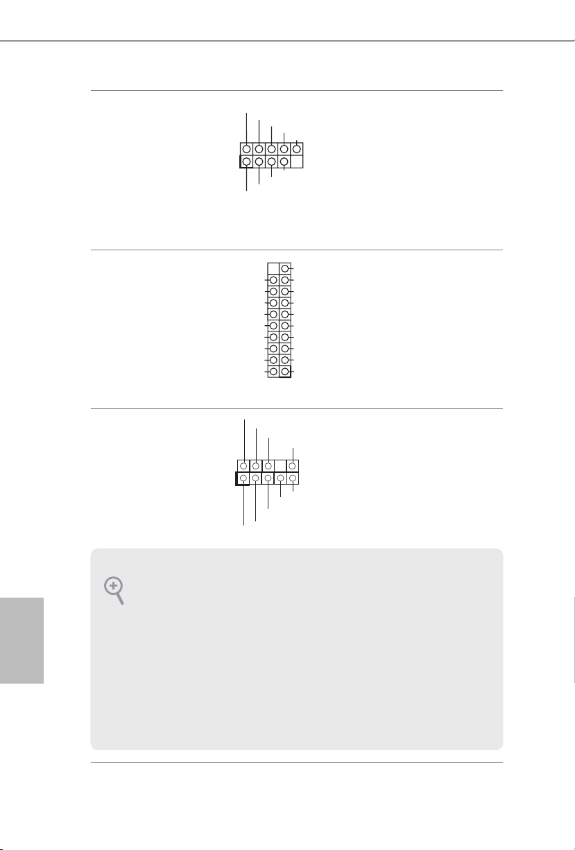
Embases USB 2.0
USB_PWR
(USB4_5 à 9 broches)
(voir p.1, No. 35)
1
USB_PWR
P-
P+
GND
DUMMY
En plus des quatre ports
USB 2.0 sur le panneau
E/S, cette carte mère
est dotée d’une embase
GND
P+
P-
supplémentaire. Chaque
embase USB 2.0 peut
prendre en charge deux
ports.
Français
1
PRESENCE#
MIC_RET
J_SENSE
OUT2_R
MIC2_R
VbusVbus
IntA_PB_SSRX-
IntA_PB_SSRX+
GND
IntA_PB_SSTX-
IntA_PB_SSTX+
GND
IntA_PB_D-
IntA_PB_D+
Dummy
OUT_RET
OUT2_L
En plus des six ports
USB 3.0 sur le panneau
E/S, cette carte mère
est dotée d’une embase
supplémentaire. Chaque
embase USB 3.0 peut
prendre en charge deux
ports.
Cette embase sert
au branchement des
appareils audio au
panneau audio frontal.
Embases USB 3.0
(USB3_6_7 19 broches)
(voir p.1, No. 9)
Embase audio du
panneau frontal
(HD_AUDIO1 à 9
broches)
(voir p.1, No. 41)
Vbus
IntA_PA_SSRX-
IntA_PA_SSRX+
GND
IntA_PA_SSTX-
IntA_PA_SSTX+
GND
IntA_PA_D-
IntA_PA_D+
GND
1
MIC2_L
1. L’audio haute dénition prend en charge la technologie Jack Sensing (détection de la che),
mais le panneau grillagé du châssis doit être compatible avec la HDA pour fonctionner correctement. Veuillez suivre les instructions gurant dans notre manuel et dans le manuel du
châssis pour installer votre système.
2. Si vous utilisez un panneau audio AC’97, veuillez le brancher sur l’embase audio du panneau
frontal en procédant comme suit :
A. branchez Mic_IN (MIC) sur MIC2_L.
B. branchez Audio_R (RIN) sur OUT2_R et Audio_L (LIN) sur OUT2_L.
C. branchez la mise à terre (GND) sur mise à terre (GND).
D. MIC_RET et OUT_RET sont exclusivement réservés au panneau audio HD. Il est inutile
de les brancher avec le panneau audio AC’97.
E. Pour activer le micro frontal, sélectionnez l’onglet «FrontMic» du panneau de contrôle
Realtek et réglez le paramètre «Volume d’enregistrement».
64
Page 67
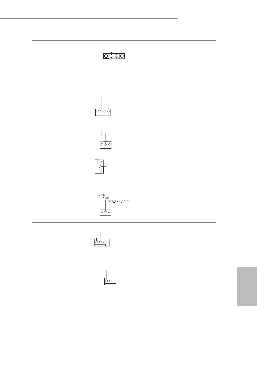
Embase du haut-parleur
GND
GND
CPU_FAN_SPEED
du châssis
(SPEAKER1 à 4 broches)
(voir p.1, No. 22)
DUMMY
1
+5V
SPEAKER
DUMMY
Z97 OC Formula
Veuillez brancher le
haut-parleur du châssis
sur cette embase.
Connecteurs du châssis
et de l’alimentation du
ventilateur
(CHA_FAN1 à 4 broches)
(voir p.1, No. 37)
(CHA_FAN2 à 3 broches)
(voir p.1, No. 32)
(CHA_FAN3 à 3 broches)
(voir p.1, No. 43)
(CHA_FAN4 3 broches)
(voir p.1, No. 44)
(PWR_FAN1 à 3
broches)
(voir p.1, No. 36)
Connecteurs du
ventilateur du processeur
(CPU_FAN1 à 4 broches)
(voir p.1, No. 3)
(CPU_FAN2 à 3 broches)
(voir p.1, No. 4)
+12V
+12V
GND
CHA_FAN_SPEED
FAN_SPEED_CONTROL
FAN_VOLTAGE
CHA_FAN_SPEED
GND
FAN_VOLTAGE
CHA_FAN_SPEED
CPU_FAN_SPEED
FAN_SPEED_CONTROL
FAN_VOLTAGE
GND
Veuillez brancher les
câbles du ventilateur
sur les connecteurs du
ventilateur, puis reliez
le l noir à la broche de
mise à terre.
Cette carte mère est dotée d’un connecteur pour
ventilateur de processeur
(Quiet Fan) à 4 broches.
Si vous envisagez de connecter un ventilateur de
processeur à 3 broches,
veuillez le brancher sur
la Broche 1-3.
Français
65
Page 68
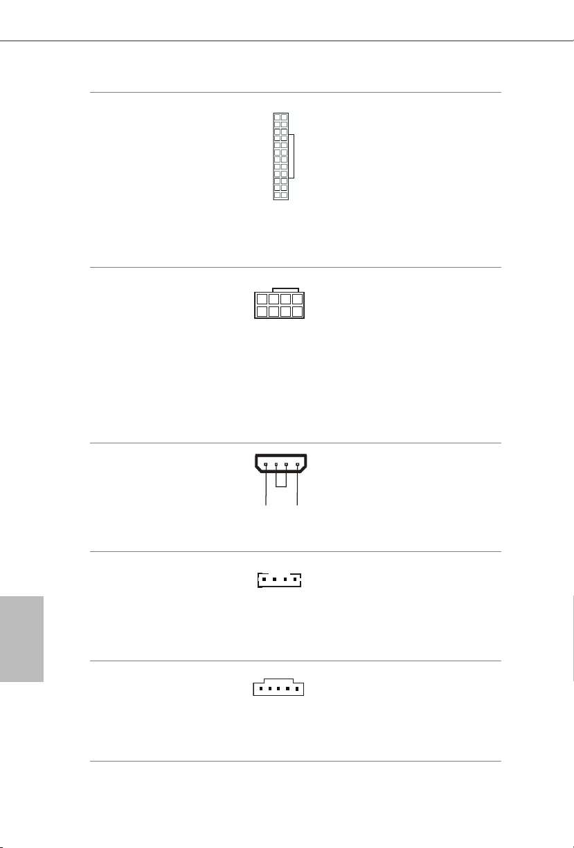
Connecteur
8
5
d’alimentation ATX
(ATXPWR1 à 24
broches)
(voir p.1, No. 8)
12
24
Cette carte mère est
dotée d’un connecteur
d’alimentation ATX à
24 broches. Pour utiliser
une alimentation ATX
1
13
à 20 broches, veuillez
eectuer les branchements sur la Broche 1 et
la Broche 13.
Français
Connecteurs
d’alimentation ATX 12V
(ATX12V1 à 8 broches)
(voir p.1, No. 2)
(ATX12V3 8 broches)
(voir p.1, No. 1)
Connecteur
d’alimentation PCIe
(PCIE_PWR1 à 4
broches)
(voir p.1, No. 40)
Connecteur sauvegarde
HDD
(SATA_PWR_1 à 4
broches)
(voir p.1, No. 29)
Connecteur underbolt
AIC
(TB1 à 5 broches)
(voir p.1, No. 34)
4
+12V DETECT
1
1
GND
Cette carte mère est dotée de deux connecteurs
d’alimentation ATX 12V
à 8 broches. Pour utiliser
une alimentation ATX
à 4 broches, veuillez
eectuer les branchements sur la Broche 1 et
la Broche 5.
Veuillez connecter un câble
d’alimentation molex à
4broches à ce connecteur
lorsque plus de trois cartes
graphiques sont installées.
Veuillez connecter le câble
de sauvegarde HDD à ce
connecteur pour gérer l'état
d'alimentation du HDD.
1
Veuillez connecter une carte
d’extension underbolt™ (AIC)
à ce connecteur via le câble
GPIO.
66
Page 69
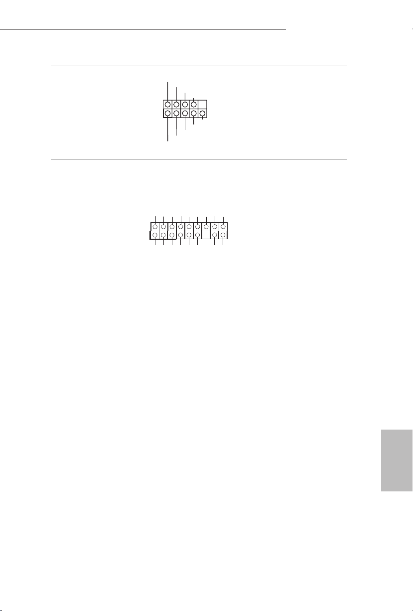
Z97 OC Formula
Embase pour port série
(COM1 à 9 broches)
(voir p.1, No. 39)
Embase TPM
(TPMS1 à 17 broches)
(voir p.1, No. 38)
RRXD1
DDTR#1
DDSR#1
CCTS#1
Cette embase COM1
prend en charge un
module de port série.
1
DDCD#1
TTXD1
GND
RRI#1
RRTS#1
Ce connecteur prend
en charge un module
TPM (Trusted
SMB _CLK_ MAIN
GND
SMB _DATA _MAIN
LAD 2
GND
LAD 1
S_P WRDWN #
Platform Module –
SER IRQ#
GND
Module de plateforme
1
+3V
LAD 3
FRA ME
PCI CLK
LAD 0
PCI RST#
sécurisée), qui permet
de sauvegarder clés,
GND
certicats numériques,
+3V SB
mots de passe et données
en toute sécurité. Le
système TPM permet
également de renforcer
la sécurité du réseau,
de protéger les identités
numériques et de
préserver l’intégrité de la
plateforme.
67
Français
Page 70
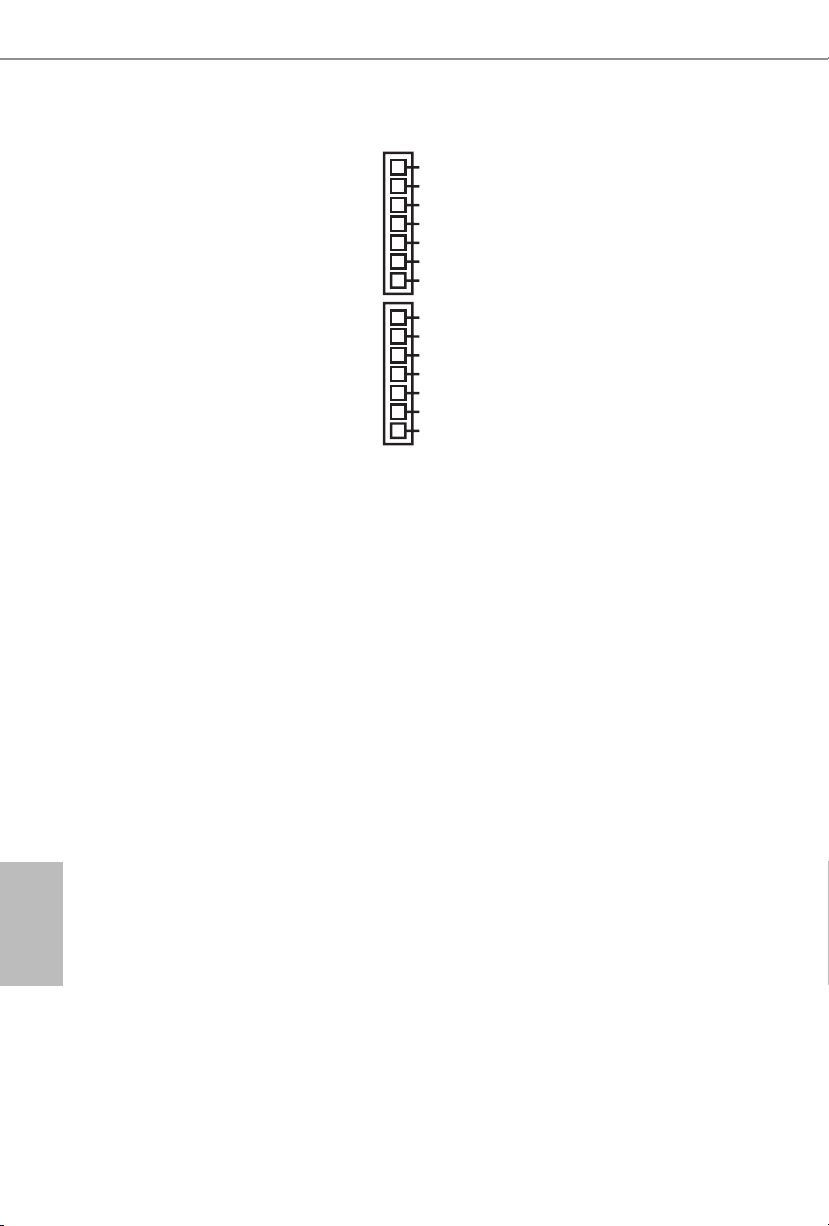
TM
V-P rob e
(VOL_CON1 7
broches, VOL_
CON2 7 broches)
(voir p.1, No. 7)
IOD
IGPU
SA
Cache
IOA
VCORE0
GND
ICC
DMI
1.5PCH
1.05PCH
VDimm
Input Volt
GND
Les utilisateurs peuvent
mesurer la tension des
composants embarqués.
IOD:
Tension ES numérique CPU
IGPU:
Tension GT
SA:
tension agent système CPU
Cache:
Tension cache CPU
IOA:
Tension ES analogique
CPU
Français
VCORE0:
tension CPU CORE0
ICC:
Tension ICC
DMI:
Tension DMI
1,5VPCH:
tension PCH 1,5V
1,05PCH:
tension PCH 1,05V
VDimm:
tension DRAM
Tension entrée:
tension d’entrée CPU
68
Page 71
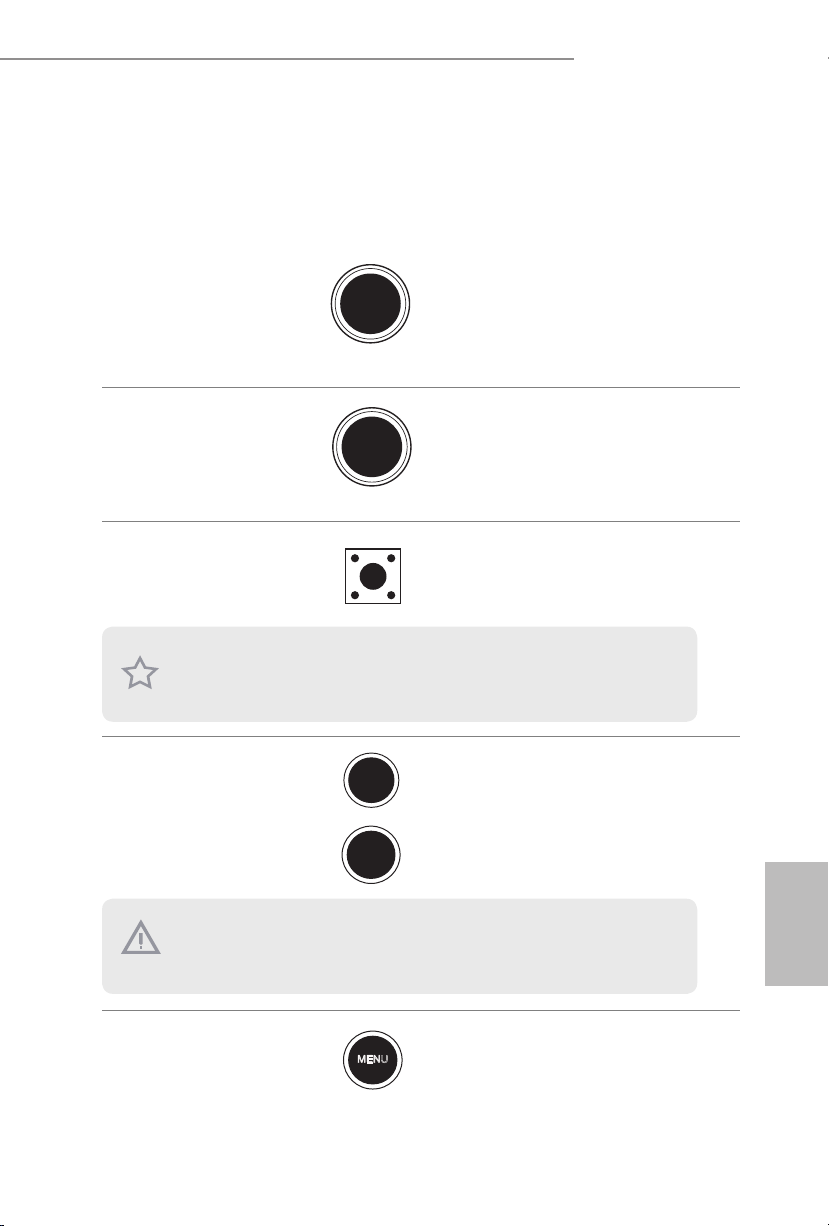
Z97 OC Formula
+
-
1.5 Boutons intelligents
La carte mère est équipée de dix boutons intelligents: Bouton d’alimentation, bouton
de réinitialisation, bouton eacer CMOS, boutons OC rapide, bouton menu, bouton
PCIe ON/OFF, bouton mode lent, bouton sélection BIOS et bouton mode LN2.
Bouton de mise en marche
(PWR)
(voir p.1, No. 24)
Bouton de réinitialisation
(RST)
(voir p.1, No. 25)
Bouton d’eacement CMOS
(CLRCBTN1)
(voir p.4, No. 4)
Cette fonction est uniquement disponible lorsque l’ordinateur est éteint et son cordon
d’alimentation débranché.
Boutons + / - Rapid
OC
(MINUS:voir p.1,
No. 27)
(PLUS:voir p.1, No. 28)
Power
Reset
Le bouton de mise en marche
permet aux utilisateurs
d’allumer le système
rapidement.
Le bouton de réinitialisation
permet aux utilisateurs
de réinitialiser le système
rapidement.
Le bouton d’eacement CMOS
permet aux utilisateurs d’eacer
les valeurs CMOS rapidement.
Les boutons + / - OC rapide
permettent à l'utilisateur de
régler rapidement et aisément
la fréquence de l'OC via Rapid
OC.
La réponse de l’overclocking dépend de la conguration du système – capacité mémoire, solution thermique etc. L’overclocking peut aecter la stabilité de votre système, voire provoquer des
dommages aux composants et aux périphériques du système. Nous ne pourrons en aucun cas
être tenus pour responsables des dommages éventuels provoqués par l’overclocking.
Bouton menu
(MENU:voir p.1, No.
30)
MENU
Français
Utilisez le bouton MENU dans
Rapid OC pour basculer rapidement entre diérentes options de
surcadençage, telles que BCLK,
Ratio et Cache Ratio.
69
Page 72
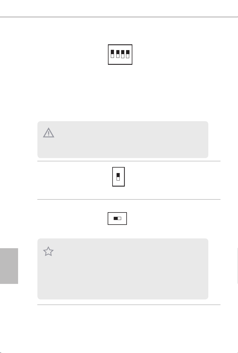
Interrupteur marche/
AB
arrêt PCIe
(PCIE_SWITCH)
(voir p.1, No. 33)
ON
1234
2: PCIE2
1: PCIE1
4: PCIE6
3: PCIE4
L’interrupteur marche/arrêt
PCIe permet à l’utilisateur
d’activer et de désactiver les
fentes PCIE x16 correspondantes. Si l’une des 16 cartes PCIE
installées est défectueuse, vous
pouvez utiliser l’interrupteur
marche/arrêt PCIE pour
détecter cette carte défectueuse
d’un seul clic sans devoir retirer
toutes les autres cartes.
1. Veillez à éteindre le système avant de modier l’interrupteur.
2. Lors de l’utilisation de l’interrupteur marche/arrêt PCIe, votre carte PCIE peut être endommagée si elle n’a pas été conçue correctement. Pour plus de détails sur les spécications de
votre carte, veuillez contacter le revendeur de la carte.
3. L’interrupteur marche/arrêt PCIe sert uniquement au débogage. Si vous ne souhaitez pas
utiliser votre carte PCIE, veuillez la retirer de la carte mère.
Français
70
Interrupteur mode
lent
(SLOWMODE)
(voir p.1, No. 19)
Interrupteur de
sélection du BIOS
(BIOS_SEL1)
(voir p.1, No. 20)
Cette carte mère est dotée de deux BIOS – un BIOS principal (BIOS_A), et un BIOS de
sauvegarde (BIOS_B) – ce qui permet d’optimiser la protection et la stabilité du système. En
règle générale, le système utilise le BIOS principal. Toutefois, si le BIOS principal venait à être
corrompu ou endommagé, placez simplement le sélecteur en position «B» et le BIOS de secours
prendra automatiquement le relais au redémarrage du système. Après cela, utilisez «Secure
Backup UEFI» depuis l’utilitaire de conguration UEFI pour copier les chiers BIOS vers
le BIOS principal et rétablir le fonctionnement normal du système. Par souci de sécurité du
système, l’utilisateur ne peut pas mettre à jour le BIOS de secours manuellement. Pour identier
le BIOS actif, l’utilisateur peut consulter les témoins LED du BIOS (LED_BIOS_A ou LED_
BIOS_B).
ON
OFF
Si le mode Lent est activé, le
processeur fonctionne à une
fréquence moindre.
Le sélecteur du BIOS permet
au système de démarrer depuis
le BIOS A ou le BIOS B.
Page 73
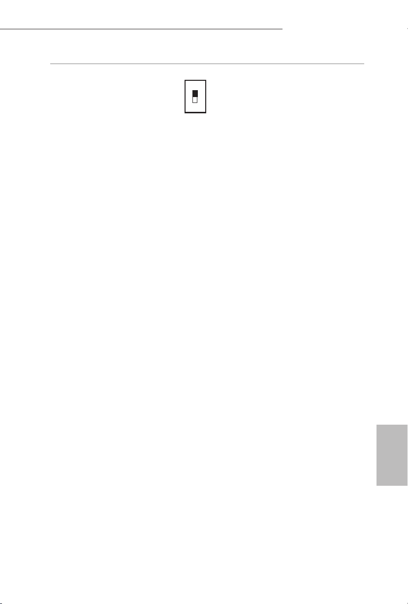
Z97 OC Formula
Interrupteur mode LN2
(LN2MODE)
(voir p.1, No. 31)
ON
OFF
Le mode LN2 aide à éliminer
le bogue associé au démarrage
à froid des processeurs en cas
d’overclocking extrême au
nitrogène liquide.
71
Français
Page 74
1 Introduzione
Grazie per aver acquistato la scheda madre ASRock Z97 OC Formula, una scheda
madre adabile prodotta secondo il severo e continuo controllo di qualità ASRock.
La scheda madre ore eccellenti prestazioni con un design robusto che si adatta
all'impegno di ASRock di orire sempre qualità e durata.
Dato che le speciche della scheda madre e del soware BIOS possono essere aggiornate, il
contenuto di questa documentazione sarà soggetto a variazioni senza preavviso. Nel caso di
eventuali modiche della presente documentazione, la versione aggiornata sarà disponibile sul
sito Web di ASRock senza ulteriore preavviso. Per il supporto tecnico correlato a questa scheda
madre, visitare il nostro sito Web per informazioni speciche relative al modello attualmente in
uso. È possibile trovare l'elenco di schede VGA più recenti e di supporto di CPU anche sul sito
Web di ASRock. Sito Web di ASRock http://www.asrock.com.
1.1 Contenuto della confezione
•Scheda madre ASRock Z97 OC Formula (formato ATX)
•Guida rapida di installazione di ASRock Z97 OC Formula
•CD di assistenza ASRock Z97 OC Formula
•1 x Schermo I/O
•4 x cavi dati Serial ATA (SATA) (opzionali)
•1 x Cavo connettore ASRock Flexible SLI Bridge
•1 x Cavo HDD Saver
•1 vite per Socket 3 M.2_SSD (NGFF)
Italiano
72
Page 75

1.2 Speciche
Z97 OC Formula
Piattaforma
CPU
Chipset
Memoria
Slot di espansione
•Fattore di forma ATX
•PCB di bra di vetro ad alta densità
•Supporta processori di quinta generazione, nuova quarta e
quarta generazione Intel® Core™ i7/i5/i3/Pentium®/Celeron®
(Socket 1150)
•Design Digi Power
•Potenza a 12 fasi
•Supporta la tecnologia Intel® Turbo Boost 2.0
•Supporto di CPU unlocked Intel® K-Series
•Supporta gamma completa overclocking BCLK ASRock
•Intel® Z97
•Tecnologia con memoria DDR3 a doppio canale
•4 alloggi DIMM DDR3
•Supporto di memoria DDR3 3400+(OC)/2933(OC)/2800(OC)
/2400(OC)/2133(OC)/1866(OC)/1600/1333/1066 non-ECC,
un-buered
•Capacità max. della memoria di sistema: 32 GB
•Supporta Intel® Extreme Memory Prole (XMP)1.3/1.2
•3 x alloggiamenti PCI Express 3.0 x16 (PCIE1/PCIE2/
PCIE4:singolo a x16 (PCIE1); doppio a x8 (PCIE1) / x8 (PCIE4);
triplo a x8 (PCIE1) / x4 (PCIE2) / x4 (PCIE4))
•1 x Alloggiamento PCI Express 2.0 x16 (PCIE6:modalità x4)
•2 alloggi PCI Express 2.0 x1
•Supporto di AMD Quad CrossFireX
3-Way CrossFireX
TM
e CrossFireXTM
•Supporta NVIDIA® Quad SLI
TM
, 4-Way CrossFireXTM,
TM
TM
e SLI
Italiano
73
Page 76

Graca
•La videograca integrata della scheda video HD Intel® e le
uscite VGA possono essere supportate soltanto con processori
con GPU integrata.
•Supporta la videograca integrata della scheda video HD Intel®:
Intel® Quick Sync Video con AVC, MVC (S3D) e MPEG-2 Full
HW Encode1, Intel® InTruTM 3D, tecnologia Intel® Clear Video
HD, Intel® InsiderTM, Intel® HD Graphics 4400/4600
•Pixel Shader 5.0, DirectX 11.1
•Memoria condivisa max. 1792 MB
•Supporta HDMI con risoluzione massima no a 4K x 2K
(4096x2304) a 24Hz
•Supporto delle funzioni Auto Lip Sync, Deep Color (12bpc),
xvYCC e HBR (High Bit Rate Audio) con porta HDMI(è
necessario un monitor conforme ad HDMI)
•Supporta HDCP con porta HDMI
•Supporto di riproduzione Full HD 1080p Blu-ray (BD) con la
porta HDMI
Italiano
74
Audio
•Audio HD a 7.1 canali con Content Protection (codec audio
Realtek ALC1150)
•Supporto audio Blu-ray Premium
•Supporto protezione da sovratensione (protezione completa
ASRock dai picchi di corrente)
•Supporto di Purity Sound
- Cappucci audio Nichicon serie Fine Gold
- 115dB SNR DAC con amplicatore dierenziale
- TI® NE5532 Premium Headset Amplier (supporta cue no
a 600 Ohm)
- Tecnologia Direct Drive
- Copertura schermata EMI
- Schermatura isolata PCB
•Supporta DTS Connect
TM
2
Page 77

Z97 OC Formula
LAN
I/O pannello
posteriore
•PCIE x 1 LAN Gigabit 10/100/1000 Mb/s
•Serie Qualcomm® Atheros® Killer
•Supporta la tecnologia Qualcomm® Atheros® Security Wake On
Internet
•Supporta Wake-On-LAN
•Supporto la protezione da fulmini/scariche elettrostatiche
(ESD) (protezione completa ASRock dai picchi di corrente)
•Supporta Energy Ecient Ethernet 802.3az
•Supporta PXE
•1 x porta mouse/tastiera PS/2
•1 x porta HDMI
•1 x porta uscita SPDIF ottico
•4 x porte USB 2.0
•4 x Porte USB 3.0 (ASMedia ASM1074 hub) (supporto
protezione da scariche elettrostatiche (ESD) (protezione
completa ASRock dai picchi di corrente))
•2 x Porte USB 3.0 (Intel® Z97) (supporto protezione da scariche
elettrostatiche (ESD) (protezione completa ASRock dai picchi
di corrente))
•1 x porta LAN RJ-45 con LED (ACT/LINK LED e SPEED
LED)
•1 x interruttore per azzerare la CMOS
•Connettori audio HD: altoparlante posteriore/centrale/basso/
ingresso linea/altoparlante anteriore/microfono
TM
E2200
Archiviazione
•6 x Connettori SATA3 6,0 Gb/s Intel® Z97, supportano RAID
(RAID 0, RAID 1, RAID 5, RAID 10, Intel Rapid Storage Technology 13 e Intel Smart Response Technology), NCQ, AHCI,
Hot Plug e la tecnologia ASRock HDD Saver
•2 x Connettori SATA3 6,0Gb/s ASMedia ASM1061, supportano
NCQ, AHCI, Hot Plug e la tecnologia ASRock HDD Saver
•1 x Connettore SATA Express (condiviso con SATA3_4,
SATA3_5 e Socket M.2)
* Supporto di prossima comunicazione
•1 x Socket 3 M.2_SSD (NGFF), supporta il modulo M.2 SATA3
6,0 Gb/s ed il modulo M.2 PCI Express no a Gen2 x2 (10 Gb/s)
Italiano
75
Page 78

Italiano
Connettore
•1 collettore porta COM
•1 x Collettore TMP
•1 x header LED di alimentazione
•2 connettori ventola CPU (1 x 4 pin, 1 x 3 pin)
•4 connettori ventola telaio (1 x 4 pin, 3 x 3 pin)
•1 connettore ventola alimentazione (3 pin)
•1 connettore alimentazione ATX 24 pin
•2 x connettori alimentazione da 12 V a 8 pin (connettore
alimentazione ad alta densità)
•1 x Connettore HDD Saver
•1 x Connettore alimentazione PCIe
•1 connettore audio pannello frontale
•1 x Connettore underbolt AIC
•1 x Collettore USB 2.0 (supporta 2 porte USB 2.0) (supporto
protezione da scariche elettrostatiche (ESD) (protezione
completa ASRock dai picchi di corrente))
•1 x Collettore USB 3.0 (supporta 2 porte USB 3.0) (supporto
protezione da scariche elettrostatiche (ESD) (protezione
completa ASRock dai picchi di corrente))
•1 x interruttore d’alimentazione con LED
•1 x interruttore di ripristino con LED
•V- Pro be
•Pulsanti OC rapido: Pulsanti +/- per regolare la frequenza OC
•1 x pulsante menu
•1 x interruttore ON/OFF PCIe
•1 x Post Status Checker (PSC)
•1 x interruttore modalità lenta
•1 x interruttore modalità LN2
•1 x interruttore di selezione BIOS
integrati
TM
: 2 x serie da 7 punti di misurazione della tensione
76
Funzione
BIOS
•BIOS legale 2 x 64Mb AMI UEFI con supporto GUI multi-
lingue (1 x Main BIOS e 1 x Backup BIOS)
•Supporto della tecnologia Secure Backup UEFI
•Eventi di riattivazione conformi a ACPI 1.1
•Supporto SMBIOS 2.3.1
•Multiregolazione tensione CPU, DRAM, PCH 1,05 V, PCH 1,5
V
Page 79
Z97 OC Formula
Hardware
•Rilevamento temperatura CPU/chassis
•Tachimetro CPU/chassis/ventola alimentazione
•Ventola silenziosa CPU/chassis (regolazione automatica veloc-
ità in base alla temperatura della CPU)
•Ventola CPU/chassis con controllo di varie velocità
•Sensore multi termico
•Monitoraggio tensione: +12V, +5V, +3,3V, tensione ingresso
CPU, tensioni interne CPU
SO
•Microso® Windows® 10 64-bit / 8.1 32-bit / 8.1 64-bit / 8 32-
bit / 8 64-bit / 7 32-bit / 7 64-bit
Certicazioni
* Per informazioni dettagliate sul prodotto, visitare il nostro sito Web: http://www.asrock.com
Prestare attenzione al potenziale rischio previsto nella pratica di overclocking, inclusa la
regolazione delle impostazioni nel BIOS, l'applicazione di tecnologia di Untied Overclocking o
l'utilizzo di strumenti di overclocking di terze parti. L'overclocking può inuenzare la stabilità
del sistema o perno provocare danni ai componenti e ai dispositivi del sistema. Occorre
eseguirlo a proprio rischio e spese. Non ci riterremo responsabili per possibili danni provocati da
overclocking.
•FCC, CE, WHQL
•ErP/EuP Ready (è necessario un alimentatore ErP/EuP Ready)
A causa della limitazione, l'eettiva dimensione della memoria può essere inferiore a 4 GB per
riservare l'uso del sistema ai sistemi operativi di Windows® a 32 bit. I sistemi operativi Windows® a 64 bit non possiedono tali limitazioni. È possibile utilizzare la RAM XFast di ASRock
per utilizzare la memoria che Windows® non può utilizzare.
Italiano
77
Page 80
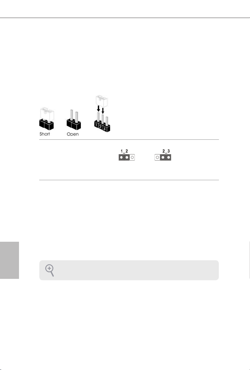
Italiano
1.3 Impostazione jumper
L'illustrazione mostra in che modo vengono impostati i jumper. Quando il cappuccio
del jumper è posizionato sui pin, il jumper è "cortocircuitato". Se sui pin non è
posizionato alcun cappuccio del jumper, il jumper è "aperto". L'illustrazione mostra
un jumper a 3 pin i cui pin1 e pin2 sono "cortocircuitati" quando un cappuccio del
jumper è posizionato su questi 2 pin.
Jumper per azzerare la
CMOS
(CLRMOS1)
(vedere pag. 1, n. 42)
CLRMOS1 permette si azzerare i dati nella CMOS. Per azzerare e reimpostare
i parametri del sistema alla congurazione predenita, spegnere il computer e
scollegare il cavo di alimentazione dalla rete. Attendere 15 secondi, quindi usare un
cappuccio jumper per cortocircuitare il pin 2 ed il pin 3 su CLRMOS1 per 5 secondi.
Tuttavia, non azzerare la CMOS subito dopo aver aggiornato il BIOS. Se è necessario
azzerare la CMOS dopo l'aggiornamento del BIOS, è necessario riavviare prima il
sistema e in seguito spegnerlo prima di eseguire l'operazione di azzeramento della
CMOS. La password, la data, l'ora e il prolo predenito dell'utente saranno azzerati
solo se viene rimossa la batteria della CMOS.
Azzerare la CMOSpredenito
78
L'interruttore per azzerare la CMOS ha la stessa funzione del jumper per azzerare la CMOS.
Page 81
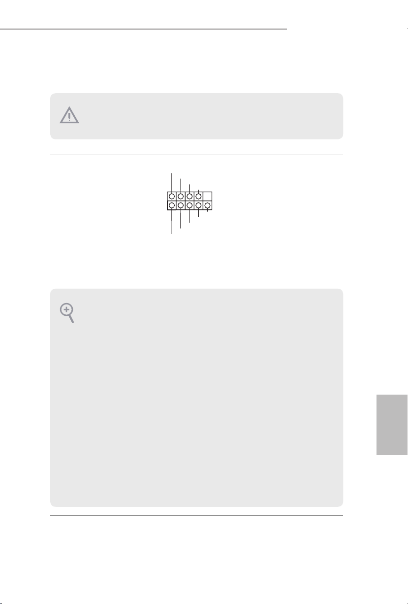
1.4 Header e connettori sulla scheda
Gli header e i connettori sulla scheda NON sono jumper. NON posizionare cappucci del jumper
su questi header e connettori. Il posizionamento di cappucci del jumper su header e connettori
provocherà danni permanenti alla scheda madre.
Z97 OC Formula
Header sul pannello del
sistema
(PANEL1 a 9 pin)
(vedere pag. 1, n. 21)
PWRBTN (interruttore di alimentazione):
collegare all'interruttore dell'alimentazione sul pannello anteriore dello chassis. È possibile
congurare il modo in cui spegnere il sistema utilizzando l'interruttore dell'alimentazione.
RESET (interruttore di reset):
collegare all'interruttore di reset sul pannello anteriore dello chassis. Premere l'interruttore di
reset per riavviare il computer se il computer si blocca e non riesce ad eseguire un normale riavvio.
PLED (LED alimentazione del sistema):
collegare all'indicatore di stato dell'alimentazione sul pannello anteriore dello chassis. Il LED
è acceso quando il sistema è in funzione. Il LED continua a lampeggiare quando il sistema si
trova nello stato di sospensione S1/S3. Il LED è spento quando il sistema si trova nello stato di
sospensione S4 o quando è spento (S5).
HDLED (LED di attività disco rigido):
collegare al LED di attività disco rigido sul pannello anteriore dello chassis. Il LED è acceso
quando il disco rigido sta leggendo o scrivendo dati.
Il design del pannello anteriore può cambiare a seconda dello chassis. Un modulo di pannello
anteriore è composto principalmente da interruttore di alimentazione, interruttore di reset,
LED di alimentazione, LED di attività disco rigido, altoparlante, ecc. Quando si collega il
modulo del pannello anteriore dello chassis a questo header, accertarsi che le assegnazioni del
lo e le assegnazioni del pin corrispondano correttamente.
1
PLED+
PLED-
HDLED-
HDLED+
PWRBTN#
GND
GND
RESET#
GND
Collegare l'interruttore
dell'alimentazione,
l'interruttore di reset e
l'indicatore dello stato del
sistema sullo chassis su
questo header secondo
la seguente assegnazione
dei pin. Annotare i pin
positivi e negativi prima di
collegare i cavi.
Italiano
79
Page 82
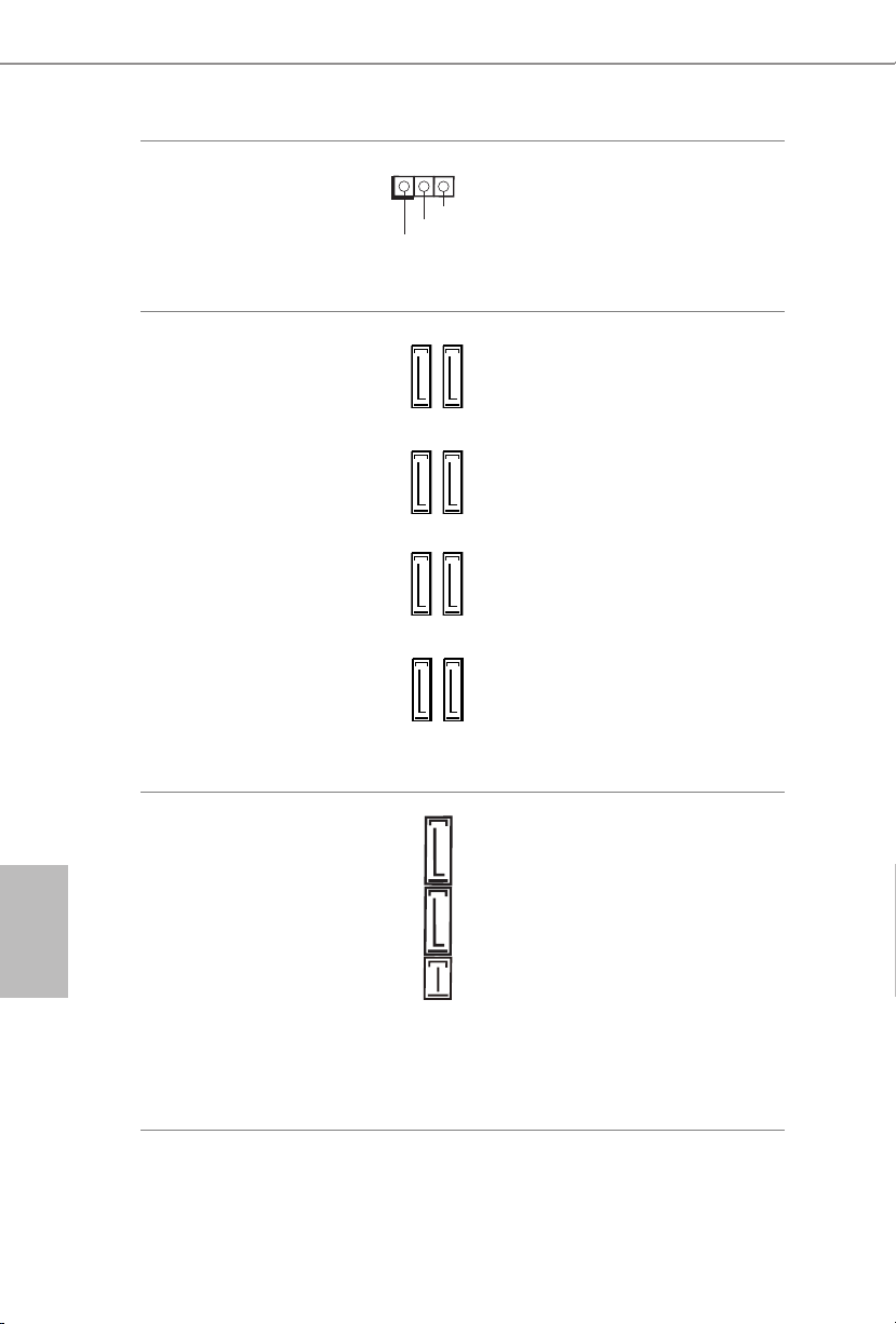
Header LED di
alimentazione
(PLED1 a 3 pin)
(vedere pag. 1, n. 26)
1
PLED+
PLED+
PLED-
Collegare il LED di
alimentazione chassis a
questo header per
indicare
lo stato di alimentazione
del sistema.
Italiano
Connettori Serial ATA3
(SATA3_0)
(vedere pag. 1, n. 12)
(SATA3_1)
(vedere pag. 1, n. 14)
(SATA3_2)
(vedere pag.1, n. 16)
(SATA3_3)
(vedere pag. 1, n. 13)
(SATA3_4)
(vedere pag. 1, n. 15)
(SATA3_5)
(vedere pag.1, n. 17)
(SATA3_A1)
(vedere pag.1, n. 10)
(SATA3_A2)
(vedere pag.1, n. 11)
Connettore Serial ATA
Express
(SATAE_1)
(vedere pag. 1, n. 18)
SATA3_A1
SATA3_0
SATA3_1
SATA3_2
Questi otto connettori
SATA3 supportano cavi di
trasmissione dati SATA per
SATA3_A2
i dispositivi d’archiviazione
interni velocità di
trasferimento dati no
a 6,0 Gb/s. I connettori
SATA3_3
SATA3_4 e SATA3_5 sono
condivisi con il connettore
SATA Express.
Per ridurre al minimo il
SATA3_4
tempo d’avvio, usare le
porte SATA Intel ® Z97
(SATA3_0) per i dispositivi
di’avvio.
SATA3_5
Collegare i dispositivi
d’archiviazione SATA o
PCIe a questo connettore.
Il connettore SATA Express
è condiviso con SATA3_4,
SATA3_5 e Socket M.2.
80
SATAE_1 SATA3_5 SATA3_4
*L'interfaccia SATA
Express è una
combinazione di
SATAE_1, SATA3_4 e
SATA3_5.
Page 83
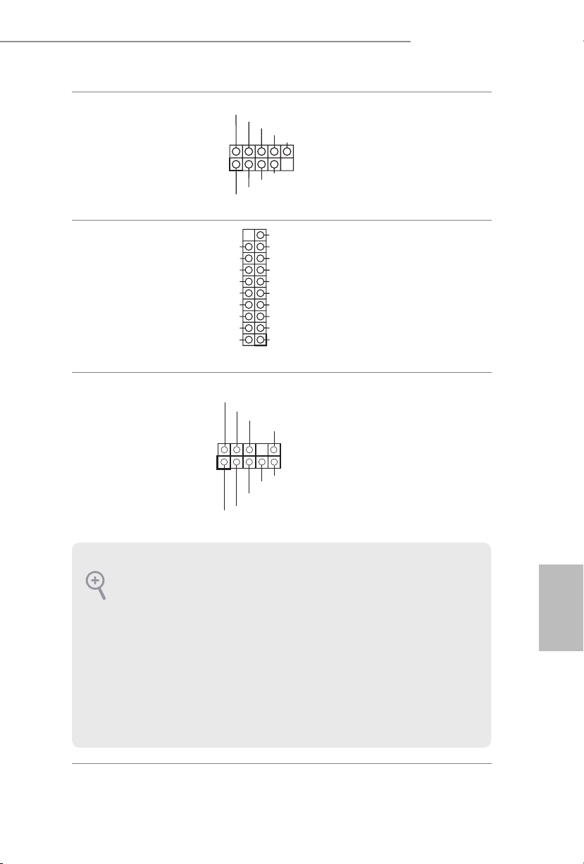
Z97 OC Formula
USB_PWR
Header USB 2.0
(USB4_5 a 9 pin)
(vedere pag. 1, n. 35)
Header USB 3.0
(19 pin USB3_6_7)
(vedere pag. 1, n. 9)
Header audio pannello
anteriore
(AUDIO1_HD a 9 pin)
(vedere pag. 1, n. 41)
1
Vbus
IntA_PA_SSRX-
IntA_PA_SSRX+
GND
IntA_PA_SSTX-
IntA_PA_SSTX+
GND
IntA_PA_D-
IntA_PA_D+
GND
1
MIC2_L
P-
P+
P+
P-
USB_PWR
PRESENCE#
MIC_RET
OUT2_R
MIC2_R
GND
DUMMY
GND
VbusVbus
IntA_PB_SSRX-
IntA_PB_SSRX+
GND
IntA_PB_SSTX-
IntA_PB_SSTX+
GND
IntA_PB_D-
IntA_PB_D+
Dummy
1
OUT_RET
OUT2_L
J_SENSE
Oltre alle quattro porte
USB 2.0 sul pannello I/O,
su questa scheda madre
vi è un header. Ciascun
header USB 2.0 può
supportare due porte.
Oltre alle sei porte USB 3.0
del pannello I/O, questa
scheda madre è dotata
di un collettore. Ciascun
header USB 3.0 può
supportare due porte.
Questo header serve a
collegare i dispositivi
audio al pannello audio
anteriore.
1. L'audio ad alta denizione supporta le funzioni Jack sensing, ma il lo del pannello sullo
chassis deve supportare HDA per funzionare correttamente. Seguire le istruzioni presenti nel
nostro manuale e nel manuale dello chassis per installare il sistema.
2. Se si utilizza un pannello audio AC’97, installarlo sull'header audio del pannello anteriore
seguendo le fasi di seguito:
A. Collegare Mic_IN (MIC) a MIC2_L.
B. Collegare Audio_R (RIN) a OUT2_R e Audio_L (LIN) a OUT2_L.
C. Collegare Ground (GND) a Ground (GND).
D. MIC_RET e OUT_RET servono soltanto per il pannello audio HD. Non è necessario collegarli per il pannello audio AC’97.
E. Per attivare il microfono anteriore, andare alla scheda “FrontMic” nel pannello di controllo
Realtek e regolare il “Volume di registrazione”.
Italiano
81
Page 84
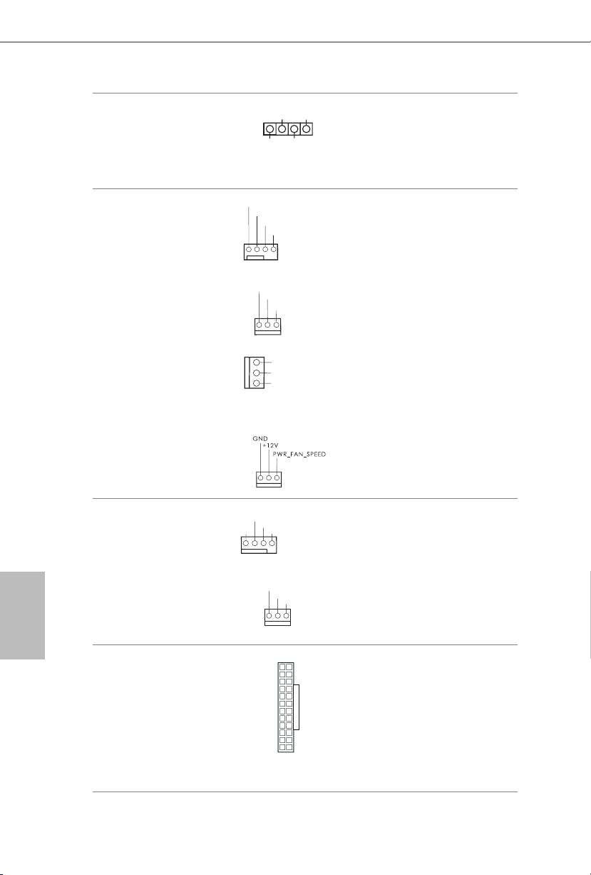
Header altoparlante chas-
CPU_FAN_SPEED
sis
(SPEAKER1 a 4 pin)
(vedere pag. 1, n. 22)
Connettori ventola dello
chassis e di alimentazione
(CHA_FAN1 a 4 pin)
(vedere pag. 1, n. 37)
(CHA_FAN2 a 3 pin)
(vedere pag. 1, n. 32)
DUMMY
1
GND
+12V
CHA_FAN_SPEED
GND
+5V
SPEAKER
DUMMY
FAN_SPEED_CONTROL
FAN_VOLTAGE
CHA_FAN_SPEED
Collegare l'altoparlante
dello chassis a questo
header.
Collegare i cavi della
ventola ai connettori della
ventola e far corrispondere
il lo nero al pin di terra.
Italiano
(CHA_FAN3 a 3 pin)
(vedere pag. 1, n. 43)
(CHA_FAN4 a 3 pin)
(vedere pag. 1, n. 44)
(PWR_FAN1 a 3 pin)
(vedere pag. 1, n. 36)
Connettori della ventola
della CPU
(CPU_FAN1 a 4 pin)
(vedere pag. 1, n. 3)
(CPU_FAN2 a 3 pin)
(vedere pag. 1, n. 4)
Connettore di
alimentazione ATX
(ATXPWR1 a 24 pin)
(vedere pag. 1, n. 8)
+12V
GND
CPU_FAN_SPEED
GND
FAN_VOLTAGE
CHA_FAN_SPEED
FAN_SPEED_CONTROL
FAN_VOLTAGE
GND
12
24
1
13
Questa scheda madre è
dotata di un connettore per
la ventola della CPU (Ventola silenziosa) a 4 pin. Se
si decide di collegare una
ventola della CPU a 3 pin,
collegarla al pin 1-3.
Questa scheda madre è
dotata di un connettore
di alimentazione ATX
a 24 pin. Per utilizzare
un'alimentazione ATX a
20 pin, collegarla lungo il
pin1 e il pin 13.
82
Page 85
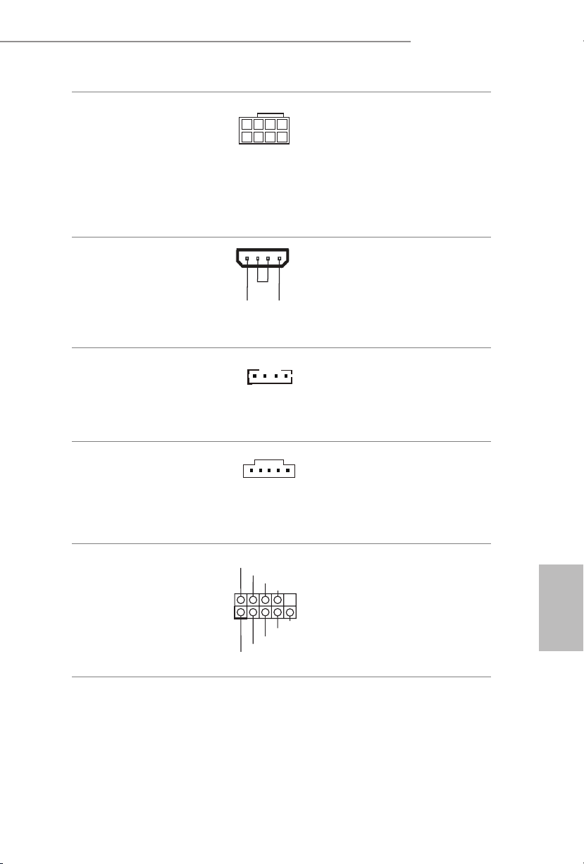
Z97 OC Formula
8
5
Connettori di
alimentazione ATX da 12
V
(ATX12V1 a 8 pin)
(vedere pag. 1, n. 2)
(ATX12V3 a 8 pin)
(vedere pag. 1, n. 1)
Connettore alimentazione
PCIe
(4-pin PCIE_PWR1)
(vedere pag. 1, n. 40)
Connettore HDD Saver
(4-pin SATA_PWR_1)
(vedere pag. 1, n. 29)
Connettoreunderbolt
AIC
(TB1 5-pin)
(vedere pag. 1, n. 34)
4
+12V DETECT
1
1
GND
Questa scheda madre è
dotata di due connettori
di alimentazione ATX da
12 V a 8 pin. Per utilizzare
un'alimentazione ATX a
4 pin, collegarla lungo il
pin1 e il pin 5.
Collegare un cavo di
alimentazione molex a 4 pin
a questo connettore quando
sono installate più di tre schede
grache.
Collegare il cavo HDD Saver a
questo connettore per gestire lo
stato d'alimentazione dell'unità
HDD.
Collegare una scheda aggiuntiva
1
underbolt™(AIC) a questo
connettore utilizzando il cavo
GPIO.
1
RRXD1
DDTR#1
TTXD1
DDCD#1
DDSR#1
CCTS#1
RRTS#1
GND
RRI#1
Questo header COM1
supporta un modulo di
porta seriale.
Italiano
83
Header porta seriale
(COM1 a 9 pin)
(vedere pag. 1, n. 39)
Page 86
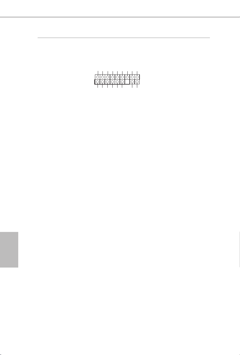
Header TPM
(TPMS1 a 17 pin)
(vedere pag. 1, n. 38)
Questo connettore
supporta il sistema TPM
(Trusted Platform Module)
SMB _CLK_ MAIN
GND
SMB _DATA _MAIN
LAD 2
GND
LAD 1
che può archiviare in
S_P WRDWN #
SER IRQ#
GND
sicurezza chiavi, certicati
1
+3V
LAD 3
FRA ME
PCI CLK
LAD 0
PCI RST#
digitali, password e dati.
Un sistema TPM permette
GND
anche di potenziare la
+3V SB
sicurezza della rete, di
proteggere identità digitali
e di garantire l'integrità
della piattaforma.
Italiano
84
Page 87
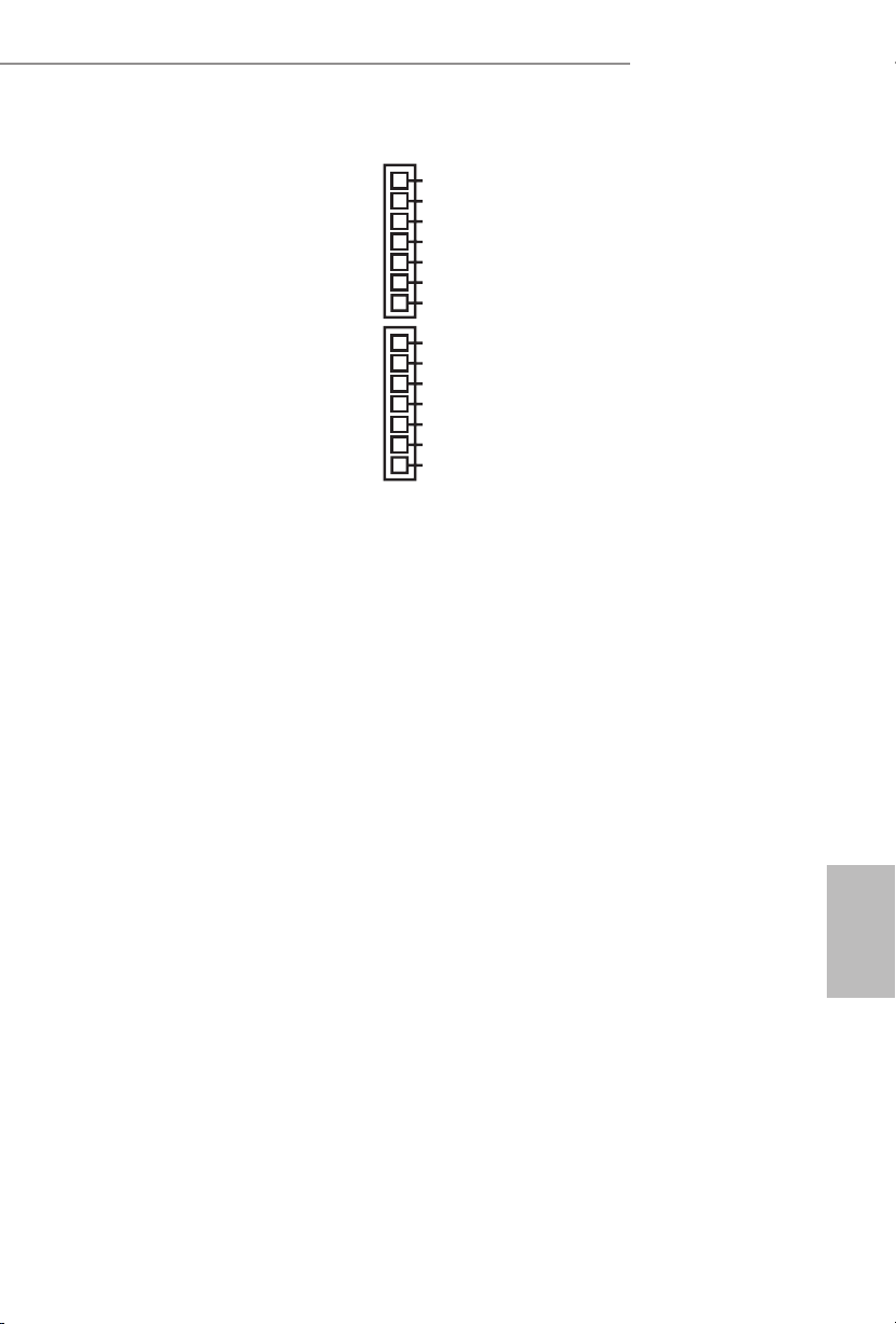
Z97 OC Formula
TM
V-P rob e
(7-pin VOL_
CON1, 7-pin VOL_
CON2)
(vedere pag. 1, n. 7)
IOD
IGPU
SA
Cache
IOA
VCORE0
GND
ICC
DMI
1.5PCH
1.05PCH
VDimm
Input Volt
GND
Gli utenti sono in grado
di misurare la tensione dei
componenti integrati.
IOD:
Tensione CPU IO digitale
IGPU:
voltaggio GT
SA:
Tensione agente sistema
CPU
Cache:
Tensione cache CPU
IOA :
Tensione CPU IO
analogico
VCORE0:
Tensione CPU CORE0
ICC:
Voltaggio ICC
DMI:
Voltaggio DMI
1,5VPCH:
Tensione PCH 1,5V
1,05PCH:
Tensione PCH 1,05V
VDimm:
Tensione DRAM
Voltaggio ingresso:
Tensione in ingresso CPU
Italiano
85
Page 88
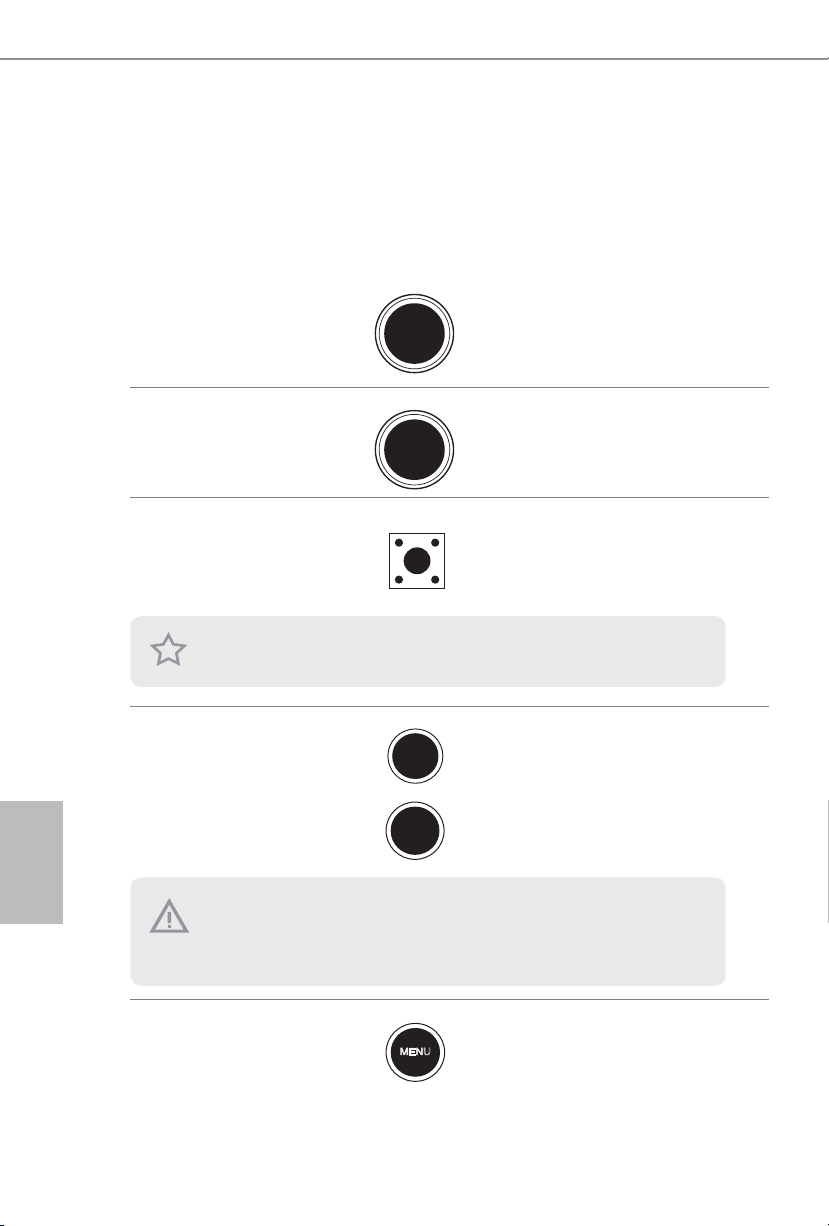
1.5 Interruttori intuitivi
+
-
La scheda madre è dotata di dieci interruttori intuitivi: Interruttore di alimentazione,
Interruttore di ripristino, Interruttore Clear CMOS, Pulsanti OC rapido, Pulsante
menu, Interruttore ON/OFF PCle, Interruttore modalità lenta, Interruttore di
selezione BIOS e Interruttore modalità LN2.
Italiano
Interruttore d’alimentazione
(PWR)
(vedere pag. 1, n. 24)
Interruttore di ripristino
(RST)
(vedere pag. 1, N. 25)
Interruttore Clear CMOS
(CLRCBTN1)
(vedere pag. 4, n. 4)
Questa funzione è operativa solo quando si spegne il computer e si scollega l'alimentatore.
Pulsanti OC rapidi
+/(MINUS:vedere pag.
1, n. 27)
(PLUS:vedere pag. 1,
n. 28)
Power
Reset
L’interruttore d’alimentazione
consente di accendere/spegnere
rapidamente il sistema.
L’interruttore di ripristino
consente di ripristinare
rapidamente il sistema.
L’interruttore Clear CMOS
consente di cancellare
rapidamente i valori CMOS.
I pulsanti OC rapidi +/- consentono agli utenti di regolare
la frequenza OC nell'OC rapido
in modo semplice e veloce.
86
Questo comportamento dell'overclock dipende dalla congurazione del sistema, come la capacità di memoria, la soluzione termica, ecc. L'overclock può inuenzare la stabilità del sistema,
o addirittura causare danni ai componenti e ai dispositivi. Non ci riterremo responsabili per
possibili danni provocati da overclocking.
Pulsante menu
(MENU:vedere pag. 1,
n. 30)
MENU
Utilizzare il tasto MENU
in Rapid OC per passare
rapidamente tra varie opzioni
di overclocking come BCLK,
Ratio e Cache Ratio.
Page 89
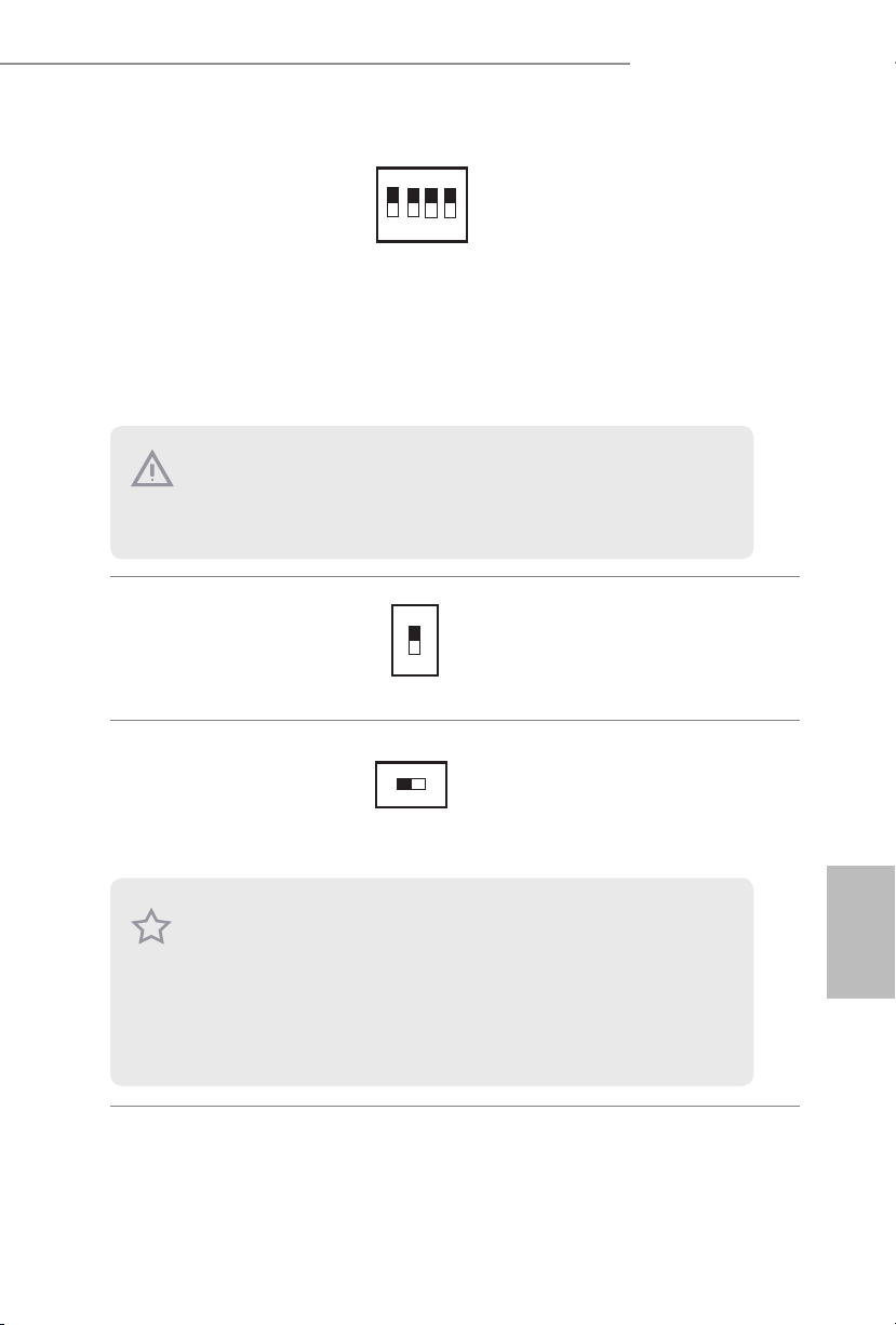
Z97 OC Formula
AB
Interruttore ON/OFF
PCIe
(PCIE_SWITCH)
(vedere pag. 1, n. 33)
ON
1234
2: PCIE2
1: PCIE1
4: PCIE6
3: PCIE4
L'interruttore ON/OFF
PCIe consente di abilitare e
disabilitare i 16 alloggi PCIE
corrispondenti. Quando una
delle 16 schede PCIE installate è guasta, è possibile usare
l'interruttore ON/OFF PCIe
per trovare quella guasta con
un singolo clic, senza rimuovere le schede.
1. Accertarsi di aver spento il sistema prima di cambiare interruttore.
2. Quando viene spento o acceso l'interruttore PCIe, la scheda PCIE potrebbe bruciarsi se è di
scarsa qualità. Per ulteriori informazioni sulle speciche della scheda, contattare il fornitore.
3. L'interruttore ON/OFF PCIe è solo per il debug. Se non si desidera utilizzare la scheda PCIE,
toglierla dalla scheda madre.
Interruttore modalità
lenta
(SLOWMODE)
ON
OFF
Se la modalità Lenta è attiva,
il processore funziona alla
frequenza più bassa.
(vedere pag. 1, n. 19)
Interruttore selezione
BIOS
(BIOS_SEL1)
L'interruttore di selezione BIOS
consente di riavviare il sistema
dal BIOS A o dal BIOS B.
(vedere pag. 1, n. 20)
Questa scheda madre è dotata di due chip BIOS, un BIOS principale (BIOS_A) e un BIOS di
backup (BIOS_B), che migliorano la sicurezza e la stabilità del sistema. Il sistema funziona
normalmente sul BIOS principale. Tuttavia, se il BIOS principale è corrotto o danneggiato,
basta semplicemente posizionare l'interruttore di selezione su "B" e il BIOS secondario si occuperà dell'avvio successivo del sistema. Quindi, usare "Secure Backup UEFI" in UEFI Setup
Utility per duplicare una copia dei le BIOS sul BIOS primario per garantire il funzionamento
normale del sistema. Per questioni di sicurezza, gli utenti non sono in grado di aggiornare il
BIOS di backup manualmente. Gli utenti possono fare riferimento ai LED BIOS (BIOS_A_LED
o BIOS_B_LED) per identicare quale BIOS è attualmente attivato.
Italiano
87
Page 90
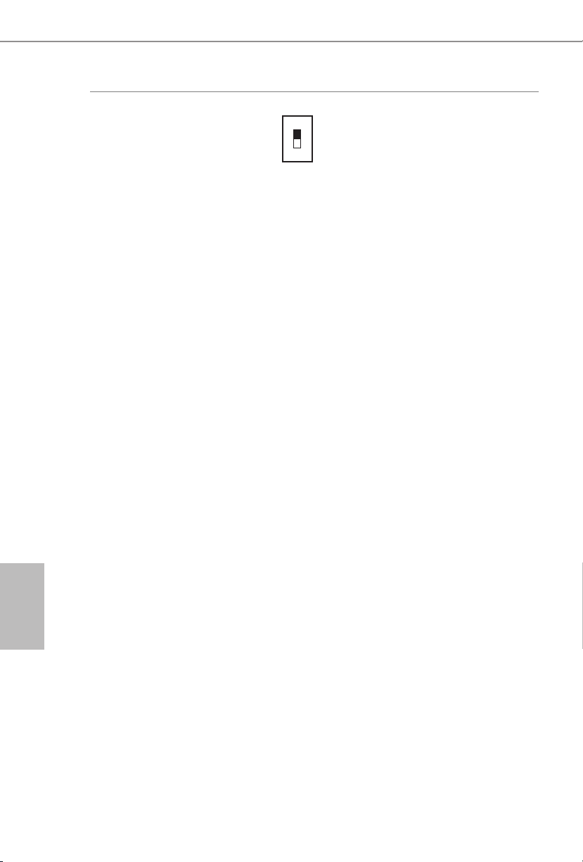
Interruttore modalità LN2
(LN2MODE)
(vedere pag. 1, n. 31)
ON
OFF
La modalità LN2 aiuta ad
eliminare i problemi di bug
dovuti all'accensione a freddo
nei processori, durante
l'overclock estremo ad azoto
liquido.
Italiano
88
Page 91
Z97 OC Formula
1 Introducción
Gracias por adquirir la placa base ASRock Z97 OC Formula, una placa base able
fabricada siguiendo el sistemáticamente estricto control de calidad de ASRock. Ofrece
un rendimiento excelente con un diseño resistente de acuerdo con el compromiso de
calidad y resistencia de ASRock.
Ya que las especicaciones de la placa base y el soware del BIOS podrán ser actualizados, el
contenido que aparece en esta documentación estará sujeto a modicaciones sin previo aviso.
Si esta documentación sufre alguna modicación, la versión actualizada estará disponible
en el sitio web de ASRock sin previo aviso. Si necesita asistencia técnica relacionada con esta
placa base, visite nuestro sitio web para obtener información especíca sobre el modelo que esté
utilizando. Podrá encontrar las últimas tarjetas VGA, así como la lista de compatibilidad de la
CPU, en el sitio web de ASRock. Sitio web de ASRock http://www.asrock.com.
1.1 Contenido del paquete
•Placa base ASRock Z97 OC Formula (factor de forma ATX)
•Guía de instalación de la placa base ASRock Z97 OC Formula
•CD de soporte de la placa base ASRock Z97 OC Formula
•1 escudo I/O
•4 cables de datos Serie ATA (SATA) (Opcional)
•1 cable conector puente SLI exible ASRock
•1 cable HDD de ahorro de energía
•1 tornillo para Socket 3 M.2_SSD (NGFF)
89
Español
Page 92

1.2 Especicaciones
Español
Plataforma
CPU
Conjunto
de chips
Memoria
•Factor de forma ATX
•PCB de bra de vidrio de alta densidad
•Admite procesadores Intel® Core™ i7/i5/i3/Pentium®/Celeron®
(zócalo 1150) de la 5a generación, la nueva 4a y la 4ª generación
•Diseño Digi Power
•Diseño de 12 fases de alimentación
•Compatible con la tecnología de Intel® Turbo Boost 2.0
•Compatible con CPU serie K desbloqueada de Intel®
•Compatible con overclocking de rango completo BCLK de
ASRock
•Intel® Z97
•Tecnología de memoria de Doble Canal DDR3
•4 ranuras DDR3 DIMM
•Compatible con memoria no-ECC, sin búfer DDR3
3400+(OC)/2933(OC)/2800(OC)/2400(OC)/2133(OC)/1866
(OC)/1600/1333/1066
•Capacidad máxima de la memoria del sistema: 32GB
•Compatible con Extreme Memory Prole (XMP)1.3/1.2 de
Intel®
90
Ranura de
expansión
•3 ranuras PCI Express 3.0 x16 (PCIE1/PCIE2/PCIE4:simple a
x16 (PCIE1); dual a x8 (PCIE1) / x8 (PCIE4); triple a x8 (PCIE1)
/ x4 (PCIE2) / x4 (PCIE4))
•1 ranura PCI Express 2.0 x16 (PCIE6:modo x4)
•2 ranuras PCI Express 2.0 x1
•Compatible con AMD Quad CrossFireX
CrossFireXTM, 3-Way CrossFireX
•Compatible con NVIDIA® Quad SLI
TM
TM
, 4-Way
y CrossFireXTM
TM
y SLI
TM
Page 93

Z97 OC Formula
Grácos
Audio
•La Tecnología visual integrada de grácos HD de Intel® y las
salidas de VGA son compatibles únicamente con procesadores
con GPU integrado.
•Compatible con la Tecnología visual integrada de grácos
HD de Intel®: Intel® Quick Sync Video con AVC, MVC (S3D)
y MPEG-2 Full HW Encode1, Intel® InTruTM 3D, Intel® Clear
Video HD Technology, Intel® InsiderTM, Intel® HD Graphics
4400/4600
•Pixel Shader 5.0, DirectX 11.1
•Memoria compartida máxima: 1792MB
•Admite la tecnología HDMI con una resolución máxima de 4K
x 2K (4096x2304) a 24 Hz
•Compatible con Auto Lip Sync, Deep Color (12bpc), xvYCC y
HBR (audio de alta velocidad de bits) con puerto HDMI
(Se necesita un monitor compatible con HDMI)
•Compatible con HDCP con puerto HDMI
•Compatible con reproducción Blu-ray (BD) Full HD de 1080p
con puerto HDMI
•7.1 Audio CH HD con Protección de contenido (Realtek
ALC1150 Audio Codec)
•Compatible con audio Blu-ray Premium
•Compatible con protección por sobretensión (protección AS-
Rock Full Spike)
•Compatible con Purity Sound
- Tapas de audio Nichion de la serie Fine Gold
- 115dB SNR DAC con amplicador diferencial
- Amplicador de auriculares de alta calidad TI® NE5532 (admite auriculares de hasta 600 ohmios)
- Tecnología Direct Drive
- Cubierta de aislaiento de EMI (interferencias electromagnéticas)
- Protección de aislamiento PCB (circuito impreso)
•Compatible con DTS Connect
TM
2
Español
91
Page 94

LAN
•1 LAN Gigabit PCIE 10/100/1000 Mb/s
•Qualcomm® Atheros® Killer
•Compatible con la Tecnología de seguridad en internet Wake
On Qualcomm® Atheros®
•Compatible con Wake-On-LAN
•Compatible con protección contra rayos y electricidad electros-
tática (protección ASRock Full Spike)
•Compatible con Ethernet de consumo eciente de energía
802.3az
•Compatible con PXE
TM
E2200 Series
Español
Panel
trasero I/O
Almacenamiento
•1 puerto de ratón/teclado PS/2
•1 puerto HDMI
•1 puerto de salida SPDIF óptica
•4 puertos USB 2.0
•4 puertos USB 3.0 (concentrador ASMedia ASM1074)
(compatible con protección contra electricidad estática
(protección ASRock Full Spike))
•2 puertos USB 3.0 (Intel® Z97) (compatible con protección
contra electricidad estática (protección ASRock Full Spike))
•1 puerto LAN RJ-45 con LED (ACT/LINK LED y SPEED LED)
•1 interruptor de borrado CMOS
•Conector de audio HD: Altavoz trasero / Central / Graves /
Entrada de línea / Altavoz frontal / Micrófono
•6 conectores SATA3 de 6,0 Gb/s de Intel® Z97, compatibilidad
con RAID (RAID 0, RAID 1, RAID 5, RAID 10, Intel Rapid
Storage Technology 13 e Intel Smart Response Technology),
NCQ, AHCI y conexión en caliente y tecnología de ahorro
ASRock HDD
•2 conectores SATA3 de 6,0 Gb/s, de ASMedia ASM1061, com-
patibles con las funciones NCQ, AHCI, y conexión en caliente
y tecnología de ahorro ASRock HDD
•1 conector Express SATA (compartido con SATA3_4, SATA3_5
y zócalo M.2)
* Compatibilidad por conrmar
•1 Socket 3 M.2_SSD (NGFF), compatible con el módulo M.2
SATA3 6,0 Gb/s y módulo M.2 PCI Express hasta Gen2 x2 (10
Gb/s)
92
Page 95

Z97 OC Formula
Conectores
•1 Cabezal de puerto COM
•1 cabezal TPM
•1 cabezal de indicador LED de alimentación
•2 Conectores de ventilador de la CPU (1 de 4 pines y 1 de 3
pines)
•4 Conectores de ventilador del chasis (1 de 4 pines y 3 de 3
pines)
•1 Conector de ventilador de alimentación (de 3 pines)
•1 Conector de alimentación ATX de 24 pines
•2 Conectores de alimentación de 8 pines y 12V (conector de
alimentación de alta densidad)
•1 conector HDD de ahorro de energía
•1 conector de alimentación PCIe
•1 Conector de audio del panel frontal
•1 conector underbolt AIC
•1 cabezal USB 2.0 (compatible con 2 puertos USB 2.0)
(compatible con protección contra electricidad estática
(protección ASRock Full Spike))
•1 cabezal USB 3.0 (compatible con 2 puertos USB 3.0)
(compatible con protección contra electricidad estática
(protección ASRock Full Spike))
•1 interruptor de alimentación con indicador LED
•1 interruptor de reseteo con indicador LED
•V- Pro be
•Botones Rapid OC: botones +/- para ajustar la frecuencia de
•1 x Botón de menú
•1 interruptor de encendido/apagado de PCIe
•1 mensaje comprobador de estado (Post Status Checker, PSC)
•1 interruptor del Modo Lento
•1 interruptor del Modo LN2
•1 interruptor de selección de BIOS
integrados
OC
TM
: 2 x 7 conjuntos de puntos de medición de voltaje
Español
93
Page 96
Función
del BIOS
•2 BIOS Legal UEFI AMI de 64Mb compatibles con interfaz
gráca de usuario multilingüe (1 BIOS Principal y 1 BIOS de
copia de seguridad)
•Compatible con tecnología UEFI de copia de seguridad segura
•Eventos de reactivación conformes con ACPI 1.1
•Compatible con SMBIOS 2.3.1
•Multiajuste de voltaje de CPU, DRAM, PCH 1,05V, PCH 1,5V
Español
Monitor
del
•Método de sensor de temperatura de la CPU/Chasis
•Tacómetro del ventilador de alimentación/CPU/Chasis
•CPU/Chasis Ventilador silencioso (Ajuste automático de ve-
locidad del ventilador del chasis por temperatura de la CPU)
•Control multivelocidad del ventilador de la CPU/Chasis
•Sensor Multi-térmico
•Control de voltaje: +12 V, +5 V, +3,3 V, voltaje de entrada de la
CPU, voltajes internos de la CPU
SO
•Microso® Windows® 10 64-bit / 8.1 32-bit / 8.1 64-bit / 8 32-
bit / 8 64-bit / 7 32-bit / 7 64-bit
Certicaciones
•FCC, CE, WHQL
•Compatible con ErP/EuP (requiere toma de alimentación com-
patible con ErP/EuP)
* Para obtener más información acerca del producto, visite nuestro sitio web: http://www.asrock.com
Tenga en cuenta que existen ciertos riesgos relacionados con el overclocking (sobreaceleración), incluyendo el ajuste de la conguración del BIOS, aplicando la Tecnología overcloking
no vinculada o utilizando las herramientas de overclocking de tercera parte. El overclocking
podría afectar la estabilidad de su sistema o incluso dañar los componentes y dispositivos de
su sistema. Si lo realiza, todos los riesgos y gastos derivados del overclocking serán de su entera
responsabilidad. No nos hacemos responsables de posibles daños producidos por el overclocking.
94
Debido a las limitaciones, el tamaño real de la memoria podrá ser inferior a 4GB para reservar
espacio para el uso del sistema en sistemas operativos Windows® de 32 bits. Los sitemas operativos Windows® de 64 bits no tienen estas limitaciones. Podrá utilizar XFast RAM de ASRock
para usar la memoria que Windows® no puede utilizar.
Page 97
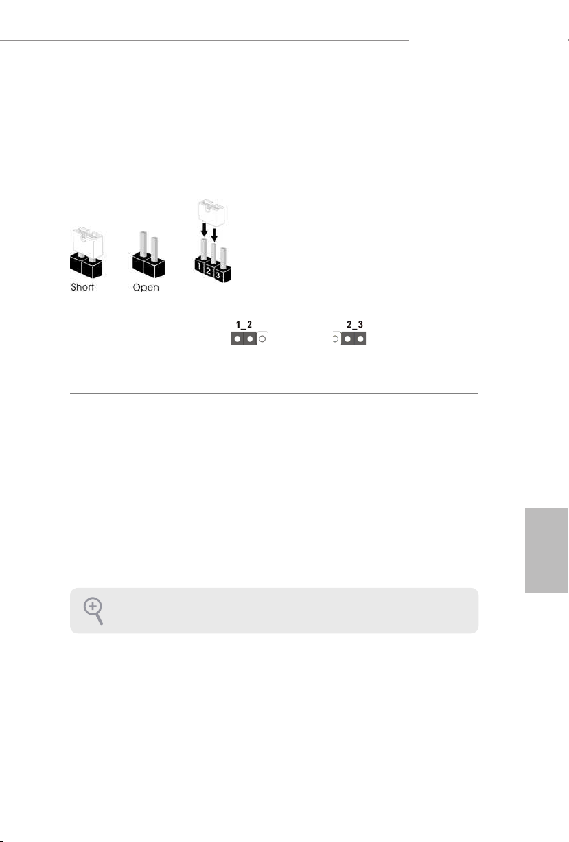
Z97 OC Formula
1.3 Instalación de los puentes
La instalación muestra cómo deben instalarse los puentes. Cuando la tapa de puente
se coloca en los pines, el puente queda “Corto”. Si no coloca la tapa de puente en los
pines, el puente queda “Abierto”. La ilustración muestra un puente de 3 pines cuyo pin
1 y pin 2 son “Cortos” cuando se coloca una tapa de puente en estos 2 pines.
Puente de borrado de
CMOS
(CLRMOS1)
(consulte la pág.1, N.º 42)
CLRMOS1 le permite borrar los datos del CMOS. Para borrar y restablecer los
parámetros del sistema a los valores predeterminados de instalación, apague el
ordenador y desenchufe el cable de alimentación de la toma de alimentación.
Después de esperar 15 segundos, utilice un tapa de puente para acortar el pin2
y el pin3 en el CLRMOS1 durante 5 segundos. Sin embargo, no borre el CMOS
justo después de que haya actualizado el BIOS. Si necesita borrar el CMOS cuando
acabe de actualizar el BIOS, deberá arrancar el sistema primero y, a continuación,
deberá apagarlo antes de que realice el borrado del CMOS. Tenga en cuenta que la
contraseña, la fecha, la hora y el perl de usuario predeterminado serán eliminados
únicamente si se retira la pila del CMOS.
Borrado de CMOSPredeterminado
Español
El interruptor de borrado CMOS tiene la misma función que el puente de borrado de CMOS.
95
Page 98
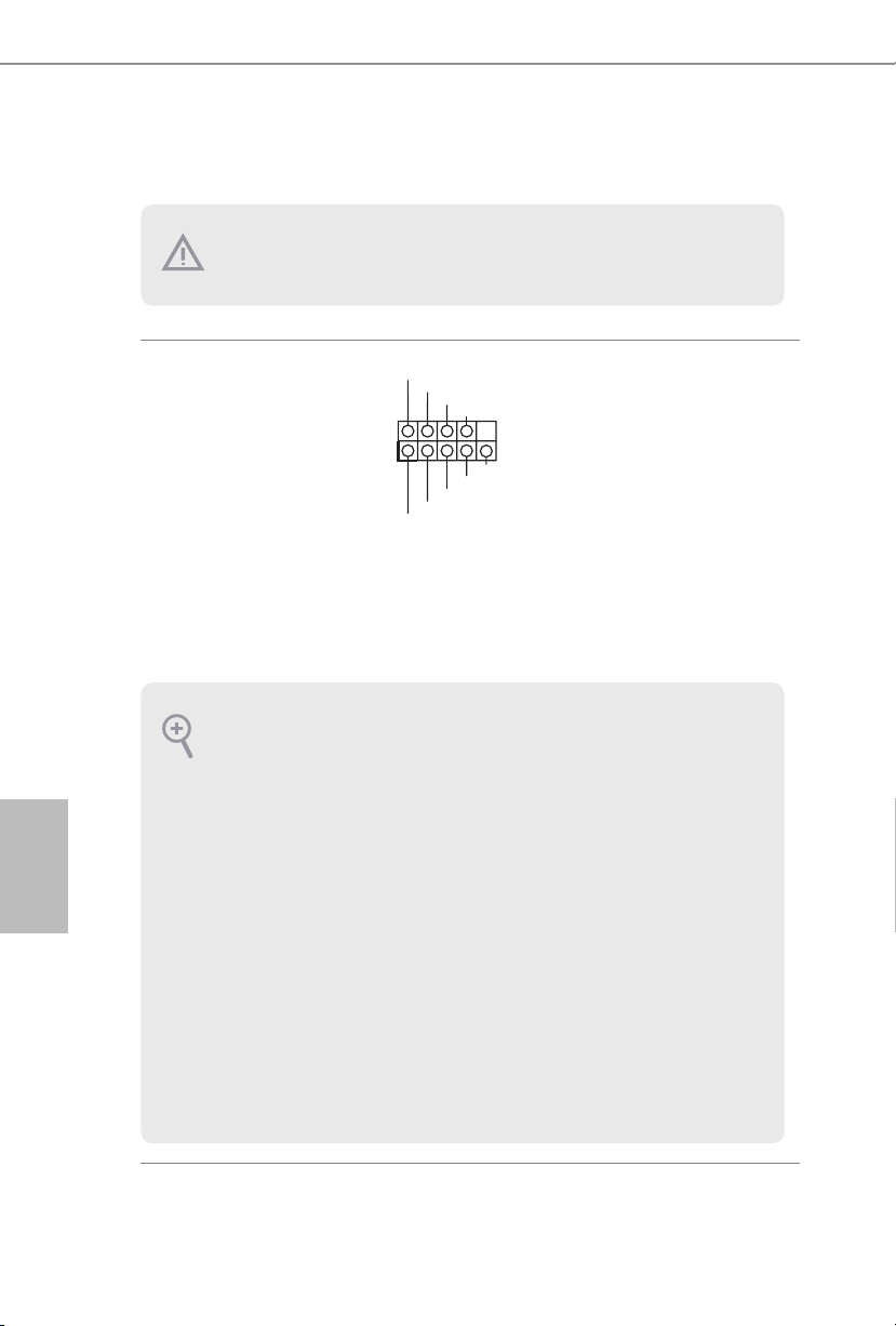
1.4 Conectores y cabezales incorporados
Los cabezales y conectores incorporados NO son puentes. NO coloque tapas de puente sobre
estos cabezales y conectores. Si coloca tapas de puente sobre los cabezales y conectores dañará
de forma permanente la placa base.
Español
Cabezal del panel del
sistema
(PANEL1 de 9 pines)
(consulte la pág.1, N.º 21)
PWRBTN (Interruptor de alimentación):
Conéctelo al interruptor de alimentación del panel frontal del chasis. Deberá congurar la
forma en la que su sistema se apagará mediante el interruptor de alimentación.
RESET (Interruptor de reseteo):
Conéctelo al interruptor de reseteo del panel frontal del chasis. Pulse el interruptor de reseteo
para resetear el ordenador si éste está bloqueado y no se puede reiniciar de forma normal.
PLED (Indicador LED de la alimentación del sistema):
Conéctelo al indicador de estado de la alimentación del panel frontal del chasis. El indicador
LED permanece encendido cuando el sistema está funcionando. El indicador LED parpadea cuando el sistema se encuentra en estado de suspensión S1/S3. El indicador LED se apaga cuando
el sistema se encuentra en estado de suspensión S4 o está apagado (S5).
HDLED (Indicador LED de actividad en el disco duro):
Conéctelo al indicador LED de actividad en el disco duro del panel frontal del chasis. El indicador LED permanece encendido cuando el disco duro está leyendo o escribiendo datos.
El diseño del panel frontal puede ser diferente dependiendo del chasis. Un módulo de panel
frontal consta principalmente de: interruptor de alimentación, interruptor de reseteo, indicador
LED de alimentación, indicador LED de actividad en el disco duro, altavoz, etc. Cuando
conecte su módulo del panel frontal del chasis a este cabezal, asegúrese de que las asignaciones
de los cables y los pines coinciden correctamente.
1
PLED+
PLED-
HDLED-
HDLED+
PWRBTN#
GND
RESET#
GND
GND
Conecte el interruptor de
alimentación, restablezca el
interruptor y el indicador
del estado del sistema del
chasis a los valores de este
cabezal, según los valores
asignados a los pines como
se indica a continuación.
Cerciórese de cuáles son
los pines positivos y los
negativos antes de conectar
los cables.
96
Page 99
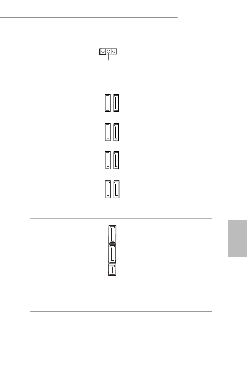
Z97 OC Formula
Cabezal de indicador LED
de alimentación
(PLED1 de 3 pines)
(consulte la pág.1, N.º 26)
Conectores Serie ATA3
(SATA3_0)
(consulte la pág.1, N.º 12)
(SATA3_1)
(consulte la pág.1, N.º 14)
(SATA3_2)
(consulte la pág.1, N.º 16)
(SATA3_3)
(consulte la pág.1, N.º 13)
(SATA3_4)
(consulte la pág.1, N.º 15)
(SATA3_5)
(consulte la pág.1, N.º 17)
(SATA3_A1)
(consulte la pág.1, N.º 10)
(SATA3_A2)
(consulte la pág.1, N.º 11)
1
SATA3_A1
SATA3_0
SATA3_1
SATA3_2
PLED+
PLED+
PLED-
SATA3_A2
SATA3_3
SATA3_4
SATA3_5
Conecte el indicador LED
de alimentación del chasis
a este cabezal para
indicar
el estado de alimentación
del sistema.
Estos ocho conectores
SATA3 son compatibles
con cables de datos SATA
para dispositivos de
almacenamiento interno
con una velocidad de
transferencia de datos de
hasta 6,0 Gb/s. SATA3_4,
SATA3_5 se comparten
con el conector express
SATA.
Para reducir el tiempo
de arranque, utilice
puertos SATA Z97 de
Intel® (SATA3_0) con sus
dispositivos de arranque.
Conector express serie
SATA
(SATAE_1)
(consulte la pág.1, N.º 18)
SATAE_1 SATA3_5 SATA3_4
Contacte o a este
conector dispositivos de
almacenamiento SATA o
PCIe. El conector express
SATA se comparte con
SATA3_4, SATA3_5 y el
zócalo M.2.
*La interfaz SATA Express
es una combinación de
SATAE_1, SATA3_4 y
SATA3_5.
Español
97
Page 100
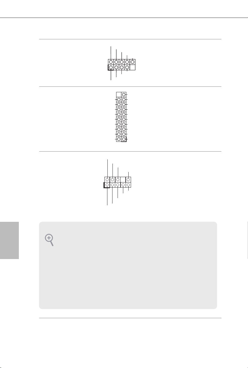
Cabezal USB 2.0
USB_PWR
(USB4_5 de 9 pines)
(consulte la pág.1, N.º 35)
1
USB_PWR
P-
P+
GND
DUMMY
Además de cuatro puertos
USB 2.0 en el panel I/O,
esta placa base contiene un
GND
P+
P-
cabezal. Cada cabezal USB
2.0 admite dos puertos.
Español
1
PRESENCE#
MIC_RET
J_SENSE
OUT2_R
MIC2_R
VbusVbus
IntA_PB_SSRX-
IntA_PB_SSRX+
GND
IntA_PB_SSTX-
IntA_PB_SSTX+
GND
IntA_PB_D-
IntA_PB_D+
Dummy
OUT_RET
OUT2_L
Además de seis puertos
USB 3.0 en el panel I/O,
esta placa base contiene un
cabezal. Cada cabezal USB
3.0 admite dos puertos.
Este cabezal se utiliza para
conectar dispositivos de
audio al panel de audio
frontal.
Cabezal USB 3.0
(USB3_6_7 de 19 pines)
(consulte la pág.1, N.º 9)
Cabezal de audio del panel
frontal
(HD_AUDIO1 de 9 pines)
(consulte la pág.1, N.º 41)
Vbus
IntA_PA_SSRX-
IntA_PA_SSRX+
GND
IntA_PA_SSTX-
IntA_PA_SSTX+
GND
IntA_PA_D-
IntA_PA_D+
GND
1
MIC2_L
1. El Audio de Alta Denición (HDA, en inglés) es compatible con el método de sensor de
conectores, sin embargo, el cable del panel del chasis deberá ser compatible con HDA para
que pueda funcionar correctamente. Siga las instrucciones que se indican en nuestro manual
y en el manual del chasis para instalar su sistema.
2. Si utiliza un panel de audio AC’97, colóquelo en el cabezal de audio del panel frontal siguiendo los pasos que se describen a continuación:
A. Conecte Mic_IN (MIC) a MIC2_L.
B. Conecte Audio_R (RIN) a OUT2_R y Audio_L (LIN) a OUT2_L.
C. Conexión a tierra (GND) a Ground (GND).
D. MIC_RET y OUT_RET se utilizan únicamente con el panel de audio HD. No es necesario
que los conecte en el panel de audio AC’97.
E. Para activar el micrófono frontal, vaya a la cha “micrófono frontal” en el panel de control
de Realtek y ajuste el “Volumen de grabación”.
98
 Loading...