

ASRock Z87M OC Formula Owner's Manual

User Manual

Version 1.0
Published May 2013
Copyright©2013 ASRock INC. All rights reserved.
Copyright Notice:
No part of this documentation may be reproduced, transcribed, transmitted, or
translated in any language, in any form or by any means, except duplication of
documentation by the purchaser for backup purpose, without written consent of
ASRock Inc.
Products and corporate names appearing in this documentation may or may not
be registered trademarks or copyrights of their respective companies, and are used
only for identication or explanation and to the owners’ benet, without intent to
infringe.
Disclaimer:
Specications and information contained in this documentation are furnished for
informational use only and subject to change without notice, and should not be
constructed as a commitment by ASRock. ASRock assumes no responsibility for
any errors or omissions that may appear in this documentation.
With respect to the contents of this documentation, ASRock does not provide
warranty of any kind, either expressed or implied, including but not limited to
the implied warranties or conditions of merchantability or tness for a particular
purpose.
In no event shall ASRock, its directors, ocers, employees, or agents be liable for
any indirect, special, incidental, or consequential damages (including damages for
loss of prots, loss of business, loss of data, interruption of business and the like),
even if ASRock has been advised of the possibility of such damages arising from any
defect or error in the documentation or product.
is device complies with Part 15 of the FCC Rules. Operation is subject to the following
two conditions:
(1) this device may not cause harmful interference, and
(2) this device must accept any interference received, including interference that
may cause undesired operation.
CALIFORNIA, USA ONLY
e Lithium battery adopted on this motherboard contains Perchlorate, a toxic substance
controlled in Perchlorate Best Management Practices (BMP) regulations passed by the
California Legislature. When you discard the Lithium battery in California, USA, please
follow the related regulations in advance.
“Perchlorate Material-special handling may apply, see ww w.dtsc.ca.gov/hazardouswaste/
perchlorate”
ASRock Website: http://www.asrock.com
e terms HDMI™ and HDMI High-Denition Multimedia Interface, and the HDMI
logo are trademarks or registered trademarks of HDMI Licensing LLC in the United
States and other countries.
Manufactured under license under U.S. Patent Nos: 5,956,674; 5,974,380; 6,487,535;
7,003,467 & other U.S. and worldwide patents issued & pending. DTS, the Symbol, &
DTS and the Symbol together is a registered trademark & DTS Connect, DTS Interactive,
DTS Neo:PC are trademarks of DTS, Inc. Product includes soware.
© DTS, Inc., All Rights Reserved.

Contents
Chapter 1 Introduction 1
1.1 Package Contents 1
1.2 Specications 2
1.3 Unique Features 7
1.4 Motherboard Layout 11
1.5 I/O Panel 13
Chapter 2 Installation 15
2.1 Installing the CPU 16
2.2 Installing the CPU Fan and Heatsink 19
2.3 Installing Memory Modules (DIMM) 20
2.4 Expansion Slots (PCI and PCI Express Slots) 22
2.5 Jumpers Setup 23
2.6 Onboard Headers and Connectors 24
2.7 Smart Switches 28
2.8 Dr. Debug 30
2.9 Using the HDMI-In Port 32
2.10 SLI
2.10.1 Installing Two SLI
TM
and Quad SLITM Operation Guide 35
TM
-Ready Graphics Cards 35
210.2 Driver Installation and Setup 37
2.11 CrossFireX
2.11.1 Installing Two CrossFireX
TM
and Quad CrossFireXTM Operation Guide 38
TM
-Ready Graphics Cards 38
2.11.2 Driver Installation and Setup 40

Chapter 3 Software and Utilities Operation 41
3.1 Installing Drivers 41
3.2 Formula Drive 42
3.3 Intel® Rapid Start Technology 46
3.4 Intel® Smart Connect Technology 51
3.5 Intel® Remote Wake Technology 56
3.5.1 Conguring and Using MeshCentral 56
3.5.2 Conguring and Using Splashtop 61
3.6 Start8 64
Chapter 4 UEFI SETUP UTILITY 67
4.1 Introduction 67
4.1.1 UEFI Menu Bar 67
4.1.2 Navigation Keys 68
4.2 Main Screen 69
4.3 OC Tweaker Screen 70
4.4 Advanced Screen 81
4.4.1 CPU Conguration 82
4.4.2 Chipset Conguration 84
4.4.3 Storage Conguration 87
4.4.4 Intel® Rapid Start Technology 89
4.4.5 Intel® Smart Connect Technology 90
4.4.6 Super IO Conguration 91
4.4.7 ACPI Conguration 92
4.4.8 USB Conguration 94

Z87M OC Formula
4.5 Tools 95
4.6 Hardware Health Event Monitoring Screen 98
4.7 Boot Screen 99
4.8 Security Screen 102
4.9 Exit Screen 103
6 1

Z87M OC Formula
Chapter 1 Introduction
ank you for purchasing ASRock Z87M OC Formula motherboard, a reliable
motherboard produced under ASRock’s consistently stringent quality control.
It delivers excellent performance with robust design conforming to ASRock’s
commitment to quality and endurance.
In this documentation, Chapter 1 and 2 contains the introduction of the
motherboard and step-by-step installation guides. Chapter 3 contains the operation
guide of the soware and utilities. Chapter 4 contains the conguration guide of
the BIOS setup.
Becau se the motherboard specications and the BIOS soware might be updated, the
content of this documentation will be subject to change without notice. In case any modications of this documentation occur, the updated version will be available on ASRock’s
website w ithout further notice. If you require technical support related to this motherboard, please visit our website for specic information about the model you are using. You
may nd the l atest VGA cards and CPU suppor t list on ASRock’s website a s well. ASRock
website http://www.asrock.com.
1.1 Package Contents
ASRock Z87M OC Formula Motherboard (Micro ATX Form Factor)
•
ASRock Z87M OC Formula Quick Installation Guide
•
ASRock Z87M OC Formula Support CD
•
4 x Serial ATA (SATA) Data Cables (Optional)
•
10 x OC Stands
•
GELID Solution GC-Extreme ermal Compound
•
1 x WiFi Module Screw
•
1 x mSATA Screw
•
English

1.2 Specications
Platform
A-Style
•
•
•
•
•
Micro ATX Form Factor
Premium Gold Capacitor design (100% Japan-made high-
quality Conductive Polymer Capacitors)
Home Cloud
Purity Sound
HDMI-In
TM
OC
Formula
Kit
CPU
OC Formula Power Kit
12 Power Phase Design
•
Digi Power
•
Dual-Stack MOSFET (DSM)
•
Multiple Filter Cap (MFC) (Filter dierent noise by 3 dierent
•
capacitors: DIP solid cap, POSCAP and MLCC)
Premium Alloy Choke (Reduce 70% core loss compare to iron
•
powder choke)
OC Formula Connector Kit
Hi-Density Power Connector (8 pin)
•
15μGold Finger (CPU sockets, memory sockets and PCIE x16
•
slots)
Distortion-Free Slot
•
OC Formula Cooling Kit
8 Layer PCB
•
4 x 2oz copper
•
GELID Solutions GC-Extreme ermal Compound
•
Supports 4th Generation Intel® CoreTM i7 / i5 / i3 / Xeon® /
•
Pentium® / Celeron® in LGA1150 Package
Supports Intel® Turbo Boost 2.0 Technology
•
Supports Intel® K-Series unlocked CPU
•
Supports ASRock BCLK Full-range Overclocking
•
English
Chipset
®
Z87
Intel
•
2 3

Memory
Expansion
Slot
Dual Channel DDR3 memory technolog y
•
4 x DDR3 DIMM slots
•
Supports DDR3 3000+(OC)/2933(OC)/2800(OC)/2400(OC)
•
/2133(OC)/1866(OC)/1600/1333/1066 non-ECC, un-buered
memory
Max. capacity of system memory: 32GB
•
Supports Intel® Extreme Memory Prole (XMP) 1.3 / 1.2
•
Distortion-Free Slot
•
2 x PCI Express 3.0 x16 slots (PCIE1/PCIE3: single at x16
•
(PCIE1); dual at x8 (PCIE1) / x8 (PCIE3))
1 x PCI Express 2.0 x4 slot
•
1 x PCI Express 2.0 x1 slot
•
1 x half mini-PCI Express slot
•
1 x mSATA/mini-PCI Express slot
•
* mSATA/mini-PCI Express slot is shared with the SATA3_4
port.
TM
Supports AMD Quad CrossFireX
•
Supports NVIDIA® Quad SLITM and SLI
•
and CrossFireXTM
TM
Z87M OC Formula
Graphics
Intel® HD Graphics Built-in Visuals and the VGA outputs can
•
be supported only with processors which are GPU integrated.
Supports Intel® HD Graphics Built-in Visuals : Intel® Quick
•
Sync Video with AVC, MVC (S3D) and MPEG-2 Full
HW Encode1, Intel® InTruTM 3D, Intel® Clear Video HD
Technology, Intel® InsiderTM, Intel® HD Graphics 4400/4600
Pixel Shader 5.0, DirectX 11.1
•
Max. shared memory 1792MB
•
Dual VGA Output: support HDMI and DisplayPort ports by
•
independent display controllers
Supports HDMI Technology with max. resolution up to 4K x
•
2K (4096x2304) @ 24Hz
Supports DisplayPort with ma x. resolution up to 4K x 2K
•
(4096x2304) @ 24Hz
Supports Auto Lip Sync, Deep Color (12bpc), xvYCC and
•
HBR (High Bit Rate Audio) with HDMI (Compliant HDMI
monitor is required)
Supports HDCP function with HDMI and DisplayPort ports
•
Supports Full HD 1080p Blu-ray (BD) playback with HDMI
•
and DisplayPort ports
English

Audio
LAN
Rear Panel
I/O
7.1 CH HD Audio with Content Protection (Realtek ALC1150
•
Aud io Codec)
Premium Blu-ray audio support
•
Supports Purity Sound ™
•
- 115dB SNR DAC with dierential amplier
- TI® NE5532 Premium Headset Amplier (supports up to
600 Ohms headsets)
- Direct Drive Technology
- EMI shielding cover
- PCB isolate shielding
Supports DTS Connect
•
Gigabit LAN 10/100/10 00 Mb/s
•
Giga PHY Intel® I217V
•
Supports Intell® Remote Wake Technology
•
Supports Wake-On-LAN
•
Supports Energy Ecient Ethernet 802.3az
•
Supports PXE
•
1 x PS/2 Mouse/Keyboard Port
•
1 x HDMI-Out Port
•
1 x HDMI-In Port
•
1 x DisplayPort
•
1 x Optical SPDIF Out Port
•
1 x eSATA Connector
•
2 x USB 2.0 Ports
•
4 x USB 3.0 Ports (Intel® Z87) (ASMedia Hub)
•
2 x USB 3.0 Ports (Intel® Z87)
•
1 x RJ-45 LAN Port with LED (ACT/LINK LED and SPEED
•
LED)
1 x Clear CMOS Button
•
HD Audio Jack: Rear Speaker / Centra l / Bass / Line in / Front
•
Speaker / Microphone
English
4 5

Storage
Connector
Z87M OC Formula
6 x SATA3 6.0 Gb/s connectors, support RAID (RAID 0,
•
RAID 1, RAID 5, RAID 10, Intel Rapid Storage Technology
12 and Intel Smart Response Technology), NCQ, AHCI and
Hot Plug
1 x eSATA connector, support RAID (RAID 0, RAID 1,
•
RAID 5, RAID 10, Intel Rapid Storage Technology 12 and
Intel Smart Response Technology), NCQ, AHCI and Hot Plug
* e eSATA connector is shared with the SATA3_1 port.
1 x IR header
•
1 x COM port header
•
1 x Power LED header
•
2 x CPU Fan connectors (1 x 4-pin, 1 x 3-pin)
•
3 x Chassis Fan connectors (1 x 4-pin, 2 x 3-pin)
•
1 x Power Fan connector (3-pin)
•
1 x 24 pin ATX power connector
•
1 x 8 pin 12V power connectors
•
(Hi-Density Power Connector)
1 x Front panel audio connector
•
2 x USB 2.0 headers (support 4 USB 2.0 ports)
•
1 x Vertical Type A USB 2.0
•
1 x USB 3.0 header (supports 2 USB 3.0 ports)
•
1 x Power Switch with LED
•
1 x Reset Switch with LED
•
1 x Clear CMOS Button
•
1 x Post Status Checker (PSC)
•
1 x Slow Mode Switch
•
1 x LN2 Mode Switch
•
1 x BIOS Selection Switch
•
BIOS
Feature
2 x 64Mb AMI UEFI Legal BIOS with Multilingual GUI sup-
•
port (1 x Main BIOS and 1 x Backup BIOS)
Supports Secure Backup UEFI Technology
•
ACPI 1.1 Compliance Wake Up Events
•
SMBIOS 2.3.1 Support
•
CPU, DRAM, PCH 1.05V, PCH 1.5V Voltage Multi-adjust-
•
ment
English
Drivers, Utilities, AntiVirus Soware (Tria l Version), Cyber-
Support
CD
•
Link MediaEspresso 6.5 Trial, Google Chrome Browser and
Toolbar, Start8, MeshCentral, Splashtop Streamer
CPU/Chassis Temperature Sensing
Hardware
•
CPU/Chassis/Power Fan Tachometer
•
CPU/Chassis Quiet Fan (Allow Chassis Fan Speed Auto-
•
Adjust by CPU Temperature)
CPU/Chassis Fan Multi-Speed Control
•
Voltage Monitoring: +12V, +5V, +3.3V, CPU Vcore
•
Microso® Windows® 8 / 8 64-bit / 7 / 7 64-bit compliant
OS
Certications
* For detailed product information, please visit our website: http://www.asrock .com
Please realiz e that the re is a certain r isk involved with o verclocking, including adjusting
the setting in the BIOS, applying Untied Overclocking Technolog y, or using third-party
overclocking to ols. O verclocking may aect your system’s stability, or even c ause damage to
the components and devices of your system. It should be don e at your ow n risk and expense.
We are not responsibl e for possible damage caused by overclo cking.
•
FCC, CE, WHQL
•
ErP/EuP Ready (ErP/EuP ready power supply is required)
•
Due to limitation , the actual memory size may be less than 4GB for the re servation for system usage under Windows® 32-bit ope rating systems. Windows® 64-bit operating systems
do not have s uch limitation s. You can use ASRock XFast R AM to utilize the memory that
Windows® cannot use.
English
6 7
Z87M OC Formula
1.3 Unique Features
ASRock Formula Drive
Formula Drive is ASRock’s multi purpose soware suite with a new interface, more
new features and improved utilities, including XFast RAM, Dehumidier, Good
Night LED, FAN-Tastic Tuning, OC Tweaker and a whole lot more.
ASRock Instant Flash
ASRock Instant Flash is a BIOS ash utility embedded in Flash ROM. is conve-
nient BIOS update tool allows you to update the system BIOS in a few clicks without
preparing an additional oppy diskette or other complicated ash utility. Just save
the new BIOS le to your USB storage and launch this tool by pressing <F6> or
<F2> during POST to enter the BIOS setup menu to access ASRock Instant Flash.
Please be noted that the USB ash drive or hard drive must use FAT32/16/12 le
system.
ASRock APP Charger
Simply by installing the ASRock APP Charger makes your iPhone/iPad/iPod Touch
charge up to 40% faster than before on your computer. ASRock APP Charger allows
you to quickly charge many Apple devices simultaneously and even supports
continuous charging when your PC enters into Standby mode (S1), Suspend to RAM
(S3), hibernation mode (S4) or power o (S5).
ASRock XFast USB
ASRock XFast USB can boost the performance of your USB storage devices. e
performance may depend on the properties of the device.
ASRock XFast LAN
ASRock XFast LAN provides faster internet access, which includes the benets
listed below. LAN Application Prioritization: You can congure your application’s
priority ideally and add new programs to the list. Lower Latency in Game: Aer
setting online game’s priority higher, it can lower the latency in games. Trac
Shaping: You can watch Youtube HD videos and download simultaneously. Real-
Time Analysis of Your Data: With the status window, you can easily recognize
which data streams you are currently transferring.
English
ASRock XFast RAM
ASRock XFast RAM is included in Formula Drive. It fully utilizes the memory
space that cannot be used under Windows® 32-bit operating systems. ASRock
XFast R AM shortens the loading time of previously visited websites, making web
surng faster than ever. And it also boosts the speed of Adobe Photoshop 5 times
faster. Another advantage of ASRock XFast RAM is that it reduces the frequency of
accessing your SSDs or HDDs in order to extend their lifespan.
ASRock Crashless BIOS
ASRock Crashless BIOS allows users to update their BIOS without fear of failing. If
power loss occurs during the BIOS updating process, ASRock Crashless BIOS will
automatically nish the BIOS update procedure aer regaining power. Please note
that BIOS les need to be placed in the root director y of your USB disk. Only USB 2.0
ports support this feature.
ASRock OMG (Online Management Guard)
Administrators are able to establish an internet curfew or restrict internet access
at specied times via OMG. You may schedule the starting and ending hours of
internet access granted to other users. In order to prevent users from bypassing
OMG, guest accounts without permission to modify the system time are required.
ASRock Internet Flash
ASRock Internet Flash downloads and updates the latest UEFI rmware version
from our servers for you without entering Windows® OS. Please setup network
conguration before using Internet Flash.
ASRock UEFI System Browser
ASRock System Browser shows the overview of your current PC and the devices
connected.
ASRock Dehumidier Function
Users may prevent motherboard damages due to dampness by enabling
“Dehumidier Function”. When enabling Dehumidier Function, the computer
will power on automatically to dehumidify the system aer entering S4/S5 state.
ASRock Easy RAID Installer
English
ASRock Easy RAID Installer can help you to copy the RAID driver from the
support CD to your USB storage device. Aer copying the RAID driver to your
USB storage device, please change “SATA Mode” to “RAID”, then you can start
installing the OS in RAID mode.
8 9
Z87M OC Formula
ASRock Easy Driver Installer
For users that don’t have an optical disk drive to install the drivers from our support
CD, Easy Driver Installer is a handy tool in the UEFI that installs the LAN driver
to your system via an USB storage device, then downloads and installs the other
required drivers automatically.
ASRock Interactive UEFI
ASRock Interactive UEFI is a blend of system conguration tools, cool sound eects
and stunning visuals. e unprecedented UEFI provides a more attractive interface
and more amusment.
ASRock Fast Boot
With ASRock’s exclusive Fast Boot technology, it takes less than 1.5 seconds to
logon to Windows 8 from a cold boot. No more waiting! e speedy boot will
completely change your user experience and behavior.
ASRock Restart to UEFI
Windows® 8 brings the ultimate boot up experience. e lightning boot up speed
makes it hard to access the UEFI setup. ASRock Restart to UEFI allows users to
enter the UEFI automatically when turning on the PC. By enabling this function,
the PC will enter the UEFI directly aer you restart.
NickShih’s OC Prole
Have you ever wondered how the global OC champion overclocks his
motherboards? Now you’ve got a chance to learn a few tricks from the champion
with NickShih’s OC Prole. It doesn’t matter whether you’re using a K-Series or
No-K Series CPU, NickShih’s OC Prole will automatically detect your CPU and
oer you dierent levels of overclocking. Have a taste of Nick’s secret recipe for
overclocking this motherboard instantly.
Fine-Tuning V-Controller
Fine-Tuning V-Controller is a new collection of voltage ne tuning options in
ASRock UEFI Setup Utility. It provides more than enough voltage conguration
options for overclockers who wish to pursuit extremes.
Timing Congurator
Timing Congurator is a fast and easy tool that provides users with an abundant
collection of subtle DRAM settings for professional tweaking. You won’t even
have to waste time on entering into the UEFI or restarting the system, Timing
Congurator is an independent application that runs under Windows® OS and your
changes will take eect immediately.
English
ASRock Good Night LED
ASRock Good Night LED technology oers you a better sleeping environment by
extinguishing the unessential LEDs. By enabling Good Night LED in the BIOS, the
Power/HDD LEDs will be switched o when the system is powered on. Good night
LED will automatically switch o the Power and Keyboard LEDs when the system
enters into Standby/Hibernation mode as well.
ASRock USB Key
In a world where time is money, why waste precious time everyday typing
usernames to log in to Windows? Why should we even bother memorizing those
foot long passwords? Just plug in the USB Key and let your computer log in to
windows automatically!
ASRock Home Cloud
is motherboard supports remote wake with the onboard Intel LAN, so you can connect
with your PC from anywhere in the world. You will be able to power your PC on or turn it
o, monitor and take control of it remotely with another smartphone, tablet or computer.
ASRock FAN-Tastic Tuning
ASRock FAN-Tastic Tuning is included in Formula Drive. Congure up to ve dif-
ferent fan speeds using the graph. e fans will automatically shi to the next speed
level when the assigned temperature is met.
ASRock Distortion-Free Slot
ASRock's new pin design for the memory slots may appear to be the same as former
designs, but actually eectively reduces distortion and promotes performance,
because we strive for perfection even in the most trivial details.
English
10 11
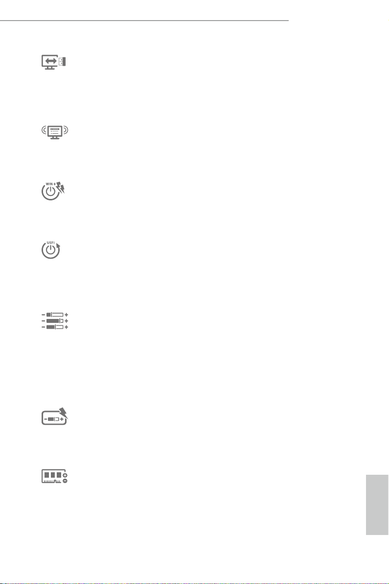
1.4 Motherboard Layout
Intel
Z87
DDR 3_A2 (6 4 bit, 24 0-pin m odule )
DDR 3_A1 (6 4 bit, 24 0-pin m odule )
DDR 3_B2 (6 4 bit, 24 0-pin m odule )
DDR 3_B1 (6 4 bit, 24 0-pin m odule )
ATX12V1
CPU_FAN1
Supe r
I/O
USB 2. 0
T: USB0
B: USB 1
ATXP WR 1
1
USB3_6 _7
CPU_FAN2
PCIE2
PCIE1
eSATA1
USB 3.0
T: USB2
B: USB3
Top:
RJ-45
USB 3.0
T: USB4
B: USB5
Top:
Centra l/Bas s
Center :
REAR SPK
Top:
LINE IN
Center :
FRONT
Bottom :
Optica l
SPDIF
Bottom :
MIC IN
PCIE3
PLED1
1
1
SPEAKER1
HDLED RESET
PLED PWRBTN
PANEL1
1
1
USB_4_5
USB_2_3
1
COM1
1
PWR_FAN1
Z87M OC Formula
8
10
12
13
14
SATA3_0_1
SATA3_2_3
SATA3_4_5
30
LAN
23
17
22
24
25
Purity
Sound
TM
USB 3.0
T: USB0
B: USB1
HDMI_IN
134
5
PS2
Keybo ard
/Mous e
HDMI1
DP_1
CLRCBTN1
8-La yer PCB
2
LN2MODE1
ON
OFF
SLOWMODE1
ON
OFF
Dr.
Debug
Vertic al
Type A USB
USB6
CHA_FAN3
11
15
16
6
7
Reset Power
18
19
CLRCBTN2
BIOS_SEL1
AB
20
21
BIOS_B_LED
64Mb
BIOS
BIOS_B
64Mb
BIOS
BIOS_A
BIOS_A_LED
CHA_FAN2
CHA_FAN1
IR1
1
26
27
28
1
HD_AUDIO1
29
CMOS
Battery
mSATA/mi ni-PC IE
CLRCMOS1
1
PCIE4
9
Z87M OC Formula
English

English
No. Description
1 ATX 12V Power Connector (ATX12V1)
2 CPU Fan Connector (CPU_FAN2)
3 CPU Fan Connector (CPU_FAN1)
4 2 x 240-pin DDR3 DIMM Slots (DDR3_A1, DDR3_B1)
5 2 x 240-pin DDR3 DIMM Slots (DDR3_A2, DDR3_B2)
6 Slow Mode Switch
7 LN2 Mode Sw itch(LN2MODE1)
8 ATX Power Connector (ATXPWR1)
9 Vertical Type A USB 2.0 (USB6)
10 USB 3.0 Header (USB3_6_7)
11 Chassis Fan Connector (CHA_FAN3)
12 SATA3 Connectors (SATA3_0_1)
13 SATA3 Connectors (SATA3_2_3)
14 SATA3 Connectors (SATA3_4_5)
15 Chassis Speaker Header (SPEAKER1)
16 Power LED Header (PLED1)
17 System Panel Header (PANEL1)
18 Power Switch (PWRBTN1)
19 Reset Switch (RSTBTN1)
20 Clear CMOS Button
21 Clear CMOS Jumper (CLRCMOS1)
22 BIOS Selection Switch (BIOS_SEL1)
23 USB 2.0 Header (USB2_3)
24 USB 2.0 Header (USB4_5)
25 COM Port Header (COM1)
26 Chassis Fan Connector (CHA_FAN2)
27 Chassis Fan Connector (CHA_FAN1)
28 IR header (IR1)
29 Front Panel Audio Header (HD_AUDIO1)
30 Power Fan Connector (PWR_FAN1)
12 13
Z87M OC Formula
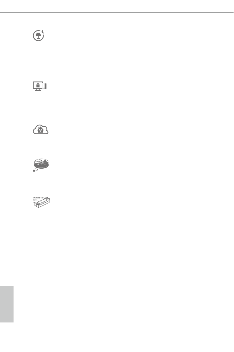
1.5 I/O Panel
698
1 2 3 4 5 7
No. Description No. Description
1 USB 2.0 Ports (USB01) 10 Microphone (Pink)
2 DisplayPort 11 Optical SPDIF Out Port
3 USB 3.0 Ports (USB3_01) 12 USB 3.0 Ports (USB3_45)
4 eSATA Connector*** 13 USB 3.0 Ports (USB3_23)
5 LAN RJ-45 Port* 14 HDMI-In Port
6 Central / Bass (Orange) 15 Clear CMOS Button (CLRCBTN)
7 Rear Speaker (Black) 16 HDMI-Out Port
8 Line In (Light Blue) 17 PS/2 Mouse/Keyboard Port
9 Front Speaker (Lime)**
1011121314151617
English
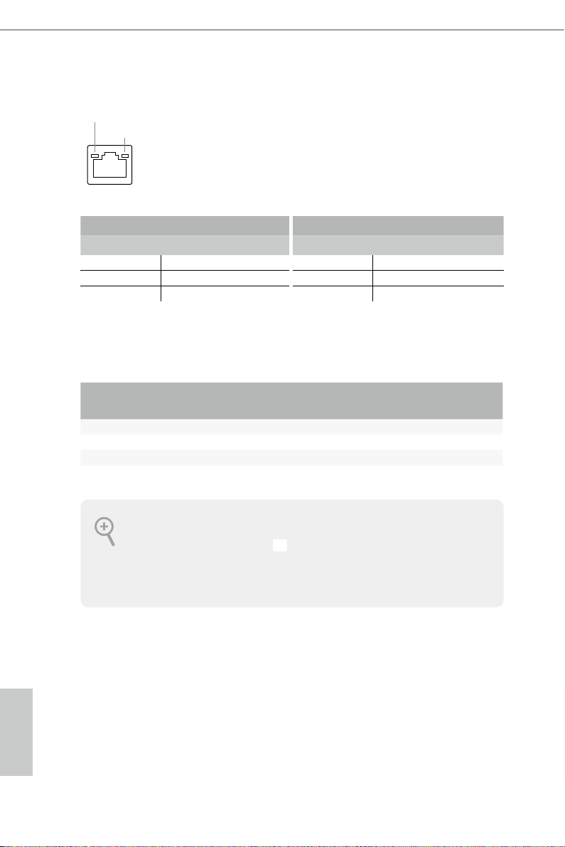
* ere are two LEDs on each LAN port. Please refer to the table below for the LAN port LED indications.
ACT/LINK LED
SPEED LED
LAN Por t
Activity / Link LED Speed LED
Status Description Status Description
O No Link O 10Mbps connection
Blinking Data Activity Orange 100Mbps connection
On Link Green 1Gbps connection
** If you use a 2- channel speaker, plea se connect the speake r’s plug into “Front Spea ker Jack”. See the table below
for connection d etails in accordance w ith the type of speaker you use.
English
Audio Output
Channels
Front Speaker
(No. 9)
Rear Speaker
(No. 7)
Central / Bass
(No. 6)
2 V -- -- --
4 V V -- --
6 V V V --
8 V V V V
To enable Multi-Streaming, you need to connect a front panel audio cable to the front
panel au dio header. Aer re starting your computer, you will nd the “Mixe r” tool on your
system. Plea se sele ct “Mixe r ToolBox” , click “Enable playback multi-streaming”, and
click “ok”. Choose “2CH”, “4CH”, “6CH”, or “8CH” and then you are a llowed to select
“Realtek HDA Primary output” to u se the Rear Speaker, Central/Ba ss, and Front Speaker,
or select “Realtek HDA Audio 2nd output” to use the front panel audio.
*** e eSATA connector supports SATA3 with cables within 1 meters.
Line In
(No. 8)
14 15

Z87M OC Formula
Chapter 2 Installation
is is an Micro ATX form factor motherboard. Before you install the motherboard,
study the conguration of your chassis to ensure that the motherboard ts into it.
Pre-installation Precautions
Take note of the following precautions before you install motherboard components
or change any motherboard settings.
Make sure to unplug the power cord before installing or removing the motherboard.
•
Failure to do so may cause physical injuries to you and damages to motherboard
components.
In order to avoid damage from static electricity to the motherboard’s components,
•
NEVER place your motherboard directly on a carpet. Also remember to use a grounded
wrist strap or touch a safety grounded object before you handle the components.
Hold components by the edges and do not touch the ICs.
•
Whenever you uninstall any components, place them on a grounded anti-static pad or
•
in the bag that comes with the components.
When placing screws to secure the motherboard to the chassis, please do not over-
•
tighten the screws! Doing so may damage the motherboard.
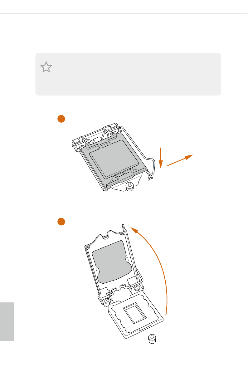
2.1 Installing the CPU
1. Before you insert the 1150-Pin CPU into the sock et, please check if the P nP cap is on the
socket, if the CPU surface is unclean, or if there are any bent pins in the sock et. Do not
force to in sert the CPU into the socket if above situation is found . Otherwise, the CPU
will be seriously damaged.
2. Unplug all power c ables before in stalling the CPU.
1
A
B
2
English
16 17
Z87M OC Formula
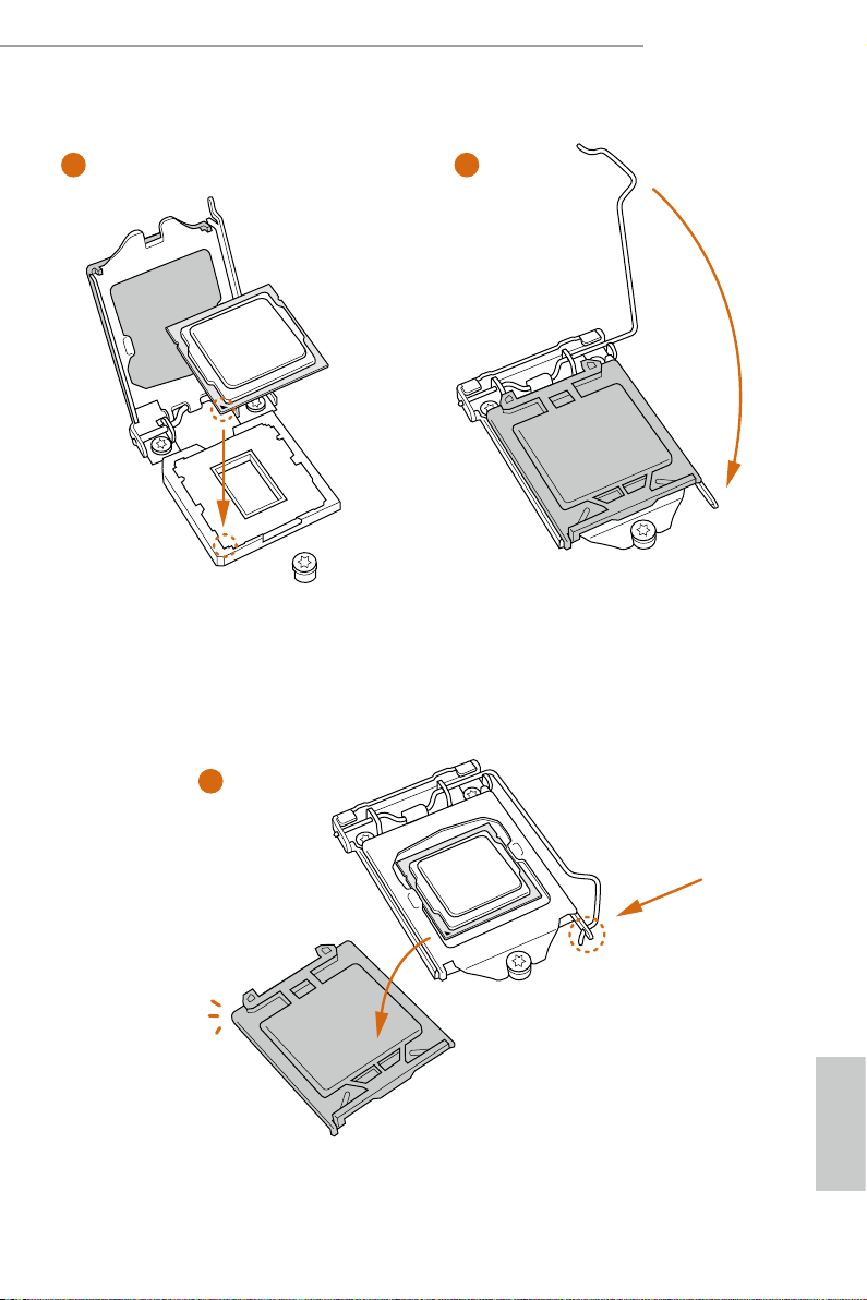
3
5
4
English

Please save and replace the cover if the processor i s removed. e cover must be placed if
you wish to return the motherboard for aer service.
English
18 19
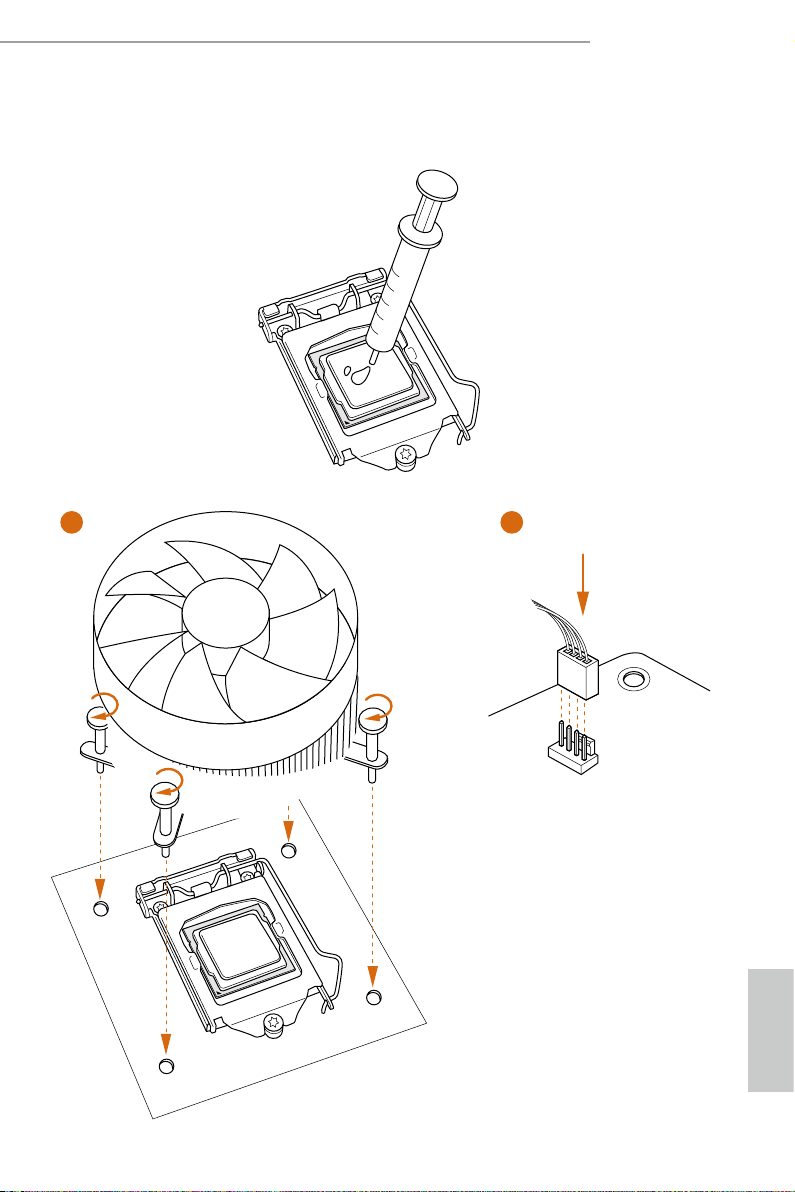
2.2 Installing the CPU Fan and Heatsink
1 2
Z87M OC Formula
FAN
CPU_
English
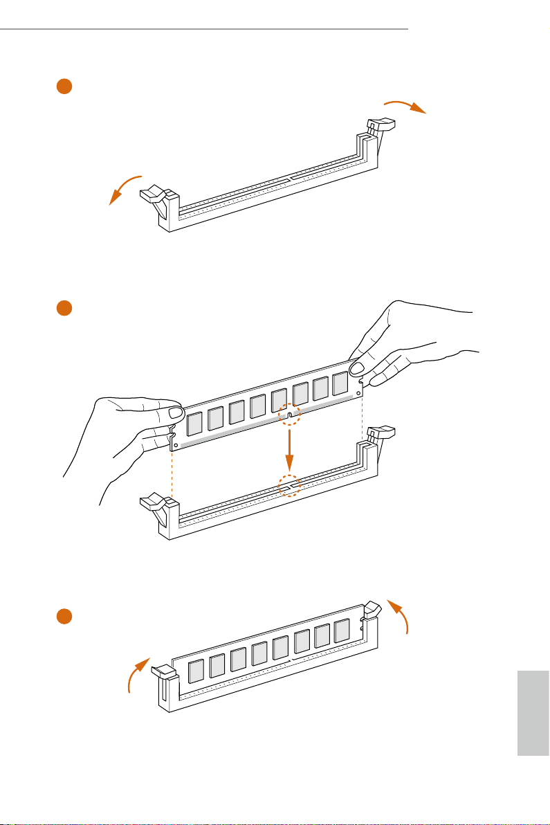
2.3 Installing Memory Modules (DIMM)
is motherboard provides four 240-pin DDR3 (Double Data Rate 3) DIMM slots,
and supports Dual Channel Memory Technology.
1. For dual channel cong uration , you always need to in stall identical (the same b rand,
speed , size and chip-type) DDR3 DI MM pairs.
2. It is unable to activate Dual Channel Memor y Technolog y with only one or three memor y
module installed.
3. It is not allowed to install a DDR or DDR2 memory module into a DDR3 slot; other wise,
this motherboard and DIMM may be damaged.
Dual Channel Memory Conguration
Priority DDR3_A1 DDR3_A2 DDR3_B1 DDR3_B2
1 Populated Populated
2 Populated Populated
3 Populated Populated Populated Populated
e DIMM only ts in one correct orie ntation. It will cause permanent dam age to the
motherboard and the DIMM if you force the DIMM into the slot at incorrect orientation.
English
20 21
Z87M OC Formula
1
2
3
English
2.4 Expansion Slots (PCI and PCI Express Slots)
ere are 4 PCI Express slots, 1 mini-PCI Express slot, and 1 mSATA/mini-PCI
Express slot on this motherboard.
Before installing an ex pansion card, please make sure that the power supply is switched o
or the power cord is unplug ged. Pl ease re ad the documentation of the expansion card and
make necessary hardware settings for the card before you start the installation.
PCIe slots:
PCIE1 (PCIe 3.0 x16 slot) is used for PCI Express x16 lane width graphics cards.
PCIE2 (PCIe 2.0 x1 slot) is used for PCI Express x1 lane width cards.
PCIE3 (PCIe 3.0 x16 slot) is used for PCI Express x8 lane width graphics cards.
PCIE4 (PCIe 3.0 x16 slot) is used for PCI Express x4 lane width graphics cards.
MINI_PCIE1 (mini-PCIe slot) is used for WiFi module.
MINI_PCIE2 (mSATA/mini-PCIe slot) is used for mSATA or mini-PCIe module.
*** e mSATA/mini-PCIe slot is shared w ith SATA3_4 connector.
PCIe Slot Congurations
PCIE1 PCIE3
Single Graphics Card x16 x8
Two Graphics Cards in
CrossFireX
TM
or SLITM Mode
For a better thermal environment, please connect a chassis fan to the motherboard’s chassis
fan connector (CHA _FAN1 or CH A_FAN2) when using multiple graphics card s.
N/A x8
English
22 23

2.5 Jumpers Setup
e illustration shows how jumpers are setup. When the jumper cap is placed on
the pins, the jumper is “Short”. If no jumper cap is placed on the pins, the jumper
is “Open”. e illustration shows a 3-pin jumper whose pin1 and pin2 are “Short”
when a jumper cap is placed on these 2 pins.
Clear CMOS Jumper
(CLRCMO S1)
(see p.11, No. 22)
CLRCMOS1 allows you to clear the data in CMOS. To clear and reset the system
parameters to default setup, please turn o the computer and unplug the power
cord from the power supply. Aer waiting for 15 seconds, use a jumper cap to
short pin2 and pin3 on CLRCMOS1 for 5 seconds. However, please do not clear
the CMOS right aer you update the BIOS. If you need to clear the CMOS when
you just nish updating the BIOS, you must boot up the system rst, and then shut
it down before you do the clear-CMOS action. Please be noted that the password,
date, time, and user default prole will be cleared only if the CMOS battery is
removed.
Default
Clear CMOS
Z87M OC Formula
e Clear CMOS Button has the same function as the Cl ear CMOS jumper.
English
2.6 Onboard Headers and Connectors
1
Onboard headers and connectors are NOT jump ers. Do NOT place jumper caps over these
heade rs and connectors. Placing jumper caps over the headers and connectors will cause
permanent damage to the motherboard.
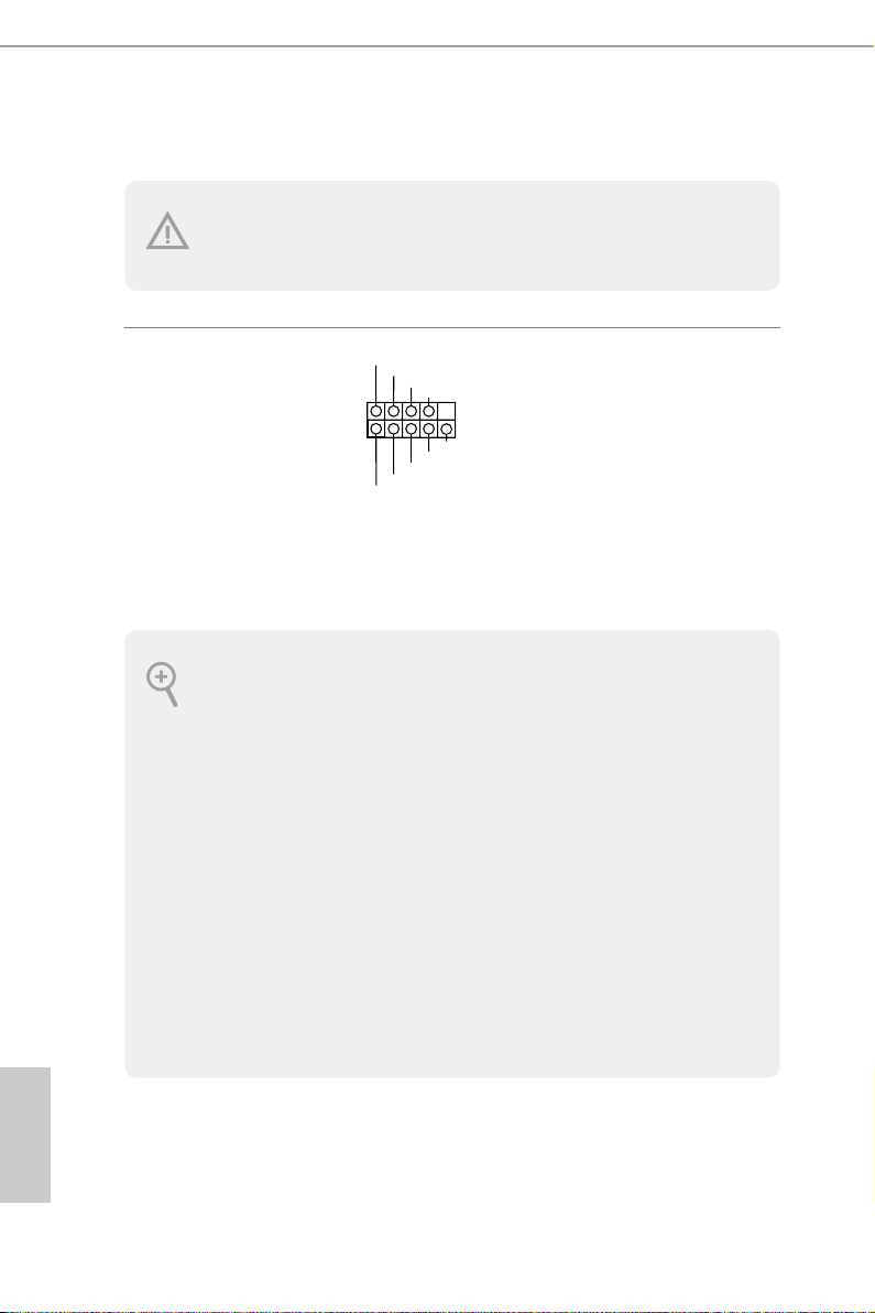
System Panel Header
(9-pi n PANEL1)
(see p.11, No. 17)
PWRBTN (Power Switch):
Connec t to the power switch on the ch assi s front panel. You may congure the way to tur n
o your system using the power switch.
RESET (Reset Switch):
Connec t to the reset switch on the chassi s front panel. Press the reset sw itch to restart the
computer if the computer f reezes and fails to per form a normal restar t.
PLED (Syste m Power LED):
Connec t to the power status indicator on the chas sis front panel. e LED i s on when the
system is operating. e LED keeps blinking when the system is in S1/S3 sleep state. e
LED is o when the system is in S4 slee p state or powered o (S5).
HDLED (Ha rd Drive Activity LED):
Connec t to the hard drive ac tivity LED on the chassis front panel. e LED is on when the
hard drive is reading or wr iting data.
e front panel de sign may dier by chassis. A front panel module mainly consists of powe r
switch, reset switch , power LED, hard dr ive activity LED, speaker and etc. When connecting your ch assi s front panel module to thi s header, make sure the wire a ssignments and the
pin assignments are matched correctly.
PLED+
PLED-
HDLED-
HDLED+
PWRBTN#
GND
RESET#
GND
GND
Connect the power
switch, reset switch and
system status indicator on
the chassis to this header
according to the pin
assignments below. Note
the positive and negative
pins before connecting
the cables.
English
24 25
 Loading...