

Page 1
Copyright Notice:
No part of this installation guide may be reproduced, transcribed, transmitted, or translated in any language, in any form or by any means, except duplication of documentation
by the purchaser for backup purpose, without written consent of ASRock Inc.
Products and corporate names appearing in this guide may or may not be registered
trademarks or copyrights of their respective companies, and are used only for identication or explanation and to the owners’ benet, without intent to infringe.
Disclaimer:
Specications and information contained in this guide are furnished for informational use
only and subject to change without notice, and should not be constructed as a commitment by ASRock. ASRock assumes no responsibility for any errors or omissions that may
appear in this guide.
With respect to the contents of this guide, ASRock does not provide warranty of any kind,
either expressed or implied, including but not limited to the implied warranties or condi-
tions of merchantability or tness for a particular purpose. In no event shall ASRock, its
directors, ofcers, employees, or agents be liable for any indirect, special, incidental, or
consequential damages (including damages for loss of prots, loss of business, loss of
data, interruption of business and the like), even if ASRock has been advised of the possibility of such damages arising from any defect or error in the guide or product.
This device complies with Part 15 of the FCC Rules. Operation is subject to the following
two conditions:
(1) this device may not cause harmful interference, and
(2) this device must accept any interference received, including interference that
may cause undesired operation.
CALIFORNIA, USA ONLY
The Lithium battery adopted on this motherboard contains Perchlorate, a toxic substance
controlled in Perchlorate Best Management Practices (BMP) regulations passed by the
California Legislature. When you discard the Lithium battery in California, USA, please
follow the related regulations in advance.
“Perchlorate Material-special handling may apply, see
www.dtsc.ca.gov/hazardouswaste/perchlorate”
ASRock Website: http://www.asrock.com
Published June 2013
Copyright©2013 ASRock INC. All rights reserved.
ASRock Z77 OC Formula Motherboard
English
1
Page 2
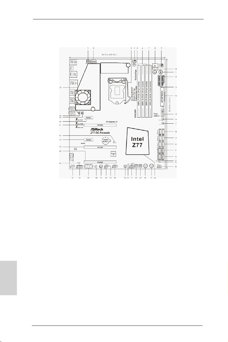
Motherboard Layout
English
2
1 ATX 12V Power Connector (ATX12V2)
2 ATX 12V Power Connector (ATX12V1)
3 1155-Pin CPU Socket
4 CPU Fan Connector (CPU_FAN1)
5 CPU Fan Connector (CPU_FAN2)
6 2 x 240-pin DDR3 DIMM Slots
(DDR3_A1, DDR3_B1, Black)
7 2 x 240-pin DDR3 DIMM Slots
(DDR3_A2, DDR3_B2, Yellow)
8 Dr. Debug
9 PCIe ON/OFF Switch
10 Rapid OC Button (-)
11 Rapid OC Button (+)
12 Post Status Checker (PSC)
13 V-ProbeTM (VOL_CON1, VOL_CON2)
14 ATX Power Connector (ATXPWR1)
15 USB 3.0 Header (USB3_6_7, Black)
16 Power Fan Connector (PWR_FAN1)
17 Chassis Fan Connector (CHA_FAN3)
18 SATA2 Connectors (SATA2_4_5, Black)
19 SATA2 Connectors (SATA2_2_3, Black)
20 SATA3 Connectors (SATA3_0_1, Yellow)
21 SATA3 Connectors (SATA3_M0_M1, Yellow)
22 SATA3 Connectors (SATA3_M2_M3, Yellow)
23 Chassis Speaker Header (SPEAKER1, Black)
24 Power LED Header (PLED1, Black)
25 System Panel Header (PANEL1, Black)
ASRock Z77 OC Formula Motherboard
26 Intel Z77 Chipset
27 Power Switch (PWRBTN)
28 Reset Switch (RSTBTN)
29 64Mb SPI Flash Memory (Backup BIOS)
30 64Mb SPI Flash Memory (Main BIOS)
31 USB 2.0 Header (USB4_5, Black)
32 BIOS Selection Jumper (BIOS_SEL1)
33 Chassis Fan Connector (CHA_FAN2)
34 USB 2.0 Header (USB6_7, Black)
35 USB 2.0 Header (USB8_9, Black)
36 Consumer Infrared Module Header (CIR1, Gray)
37 Chassis Fan Connector (CHA_FAN1)
38 Infrared Module Header (IR1)
39 SLI / XFIRE Power Connector (SLI/XFIRE_PWR1)
40 COM Port Header (COM1)
41 Front Panel Audio Header (HD_AUDIO1, Black)
42 HDMI_SPDIF Header (HDMI_SPDIF1, Black)
43 PCI Express 2.0 x16 Slot (PCIE5, Yellow)
44 PCI Express 3.0 x16 Slot (PCIE4, Yellow)
45 PCI Express 2.0 x1 Slot (PCIE3, Black)
46 Clear CMOS Jumper (CLRCMOS1)
47 PCI Express 3.0 x16 Slot (PCIE2, Black)
48 PCI Express 2.0 x1 Slot (PCIE1, Black)
49 Chassis Fan Connector (CHA_FAN4)
50 MOS Fan Connector (MOS_FAN1)
51 Twin-Power Cooling
Page 3
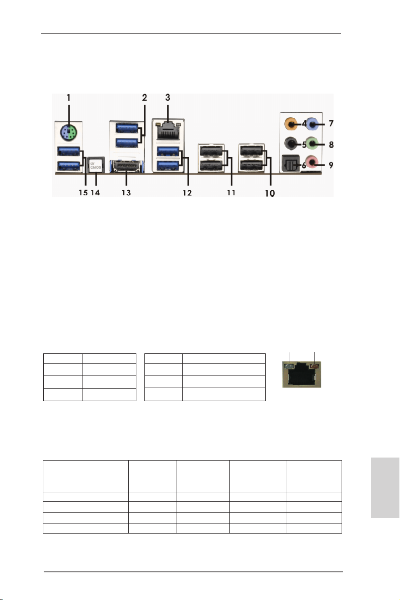
I/O Panel
1 PS/2 Keyboard/Mouse Port (Purple/Green) 9 Microphone (Pink)
2 USB 3.0 Ports (USB3_23) *** 10 USB 2.0 Ports (USB23)
* 3 LAN RJ-45 Port *** 11 USB 2.0 Ports (USB01)
4 Central / Bass (Orange) 12 USB 3.0 Ports (USB3_45)
5 Rear Speaker (Black) 13 HDMI Port (HDMI1)
6 Optical SPDIF Out Port 14 Clear CMOS Switch (CLRCBTN)
7 Line In (Light Blue) 15 USB 3.0 Ports (USB3_01)
** 8 Front Speaker (Lime)
* There are two LED next to the LAN port. Please refer to the table below for the LAN port LED
indications.
Activity/Link LED SPEED LED
Status Description Status Description
Off No Link Off 10Mbps connection
Blinking Data Activity Orange 100Mbps connection
On Link Green 1Gbps connection
LAN Port LED Indications
ACT/LINK
LED
LAN Port
SPEED
LED
If you use 2-channel speaker, please connect the speaker’s plug into “Front Speaker Jack”.
**
See the table below for connection details in accordance with the type of speaker you use.
TABLE for Audio Output Connection
Audio Output Channels Front Speaker Rear Speaker Central / Bass Line In or
(No. 8) (No. 5) (No. 4) Side Speaker
(No. 7)
2 V -- -- -4 V V -- -6 V V V -8 V V V V
ASRock Z77 OC Formula Motherboard
English
3
Page 4

To enable Multi-Streaming function, you need to connect a front panel audio cable to the front
panel audio header. After restarting your computer, you will nd “Mixer” tool on your system.
Please select “Mixer ToolBox” , click “Enable playback multi-streaming”, and click
“ok”. Choose “2CH”, “4CH”, “6CH”, or “8CH” and then you are allowed to select “Realtek HDA
Primary output” to use Rear Speaker, Central/Bass, and Front Speaker, or select “Realtek
HDA Audio 2nd output” to use front panel audio.
*** It is recommended to install the USB Keyboard/Mouse cable to USB 2.0 ports (USB01 or
USB23) instead of USB 3.0 ports.
English
4
ASRock Z77 OC Formula Motherboard
Page 5
1. Introduction
Thank you for purchasing ASRock Z77 OC Formula motherboard, a reliable motherboard produced under ASRock’s consistently stringent quality control. It delivers
excellent performance with robust design conforming to ASRock’s commitment to
quality and endurance.
This Quick Installation Guide contains introduction of the motherboard and step-bystep installation guide. More detailed information of the motherboard can be found
in the user manual presented in the Support CD.
Because the motherboard specications and the BIOS software might be
updated, the content of this manual will be subject to change without no-
tice. In case any modications of this manual occur, the updated version
will be available on ASRock website without further notice. You may nd
the latest VGA cards and CPU support lists on ASRock website as well.
ASRock website http://www.asrock.com
If you require technical support related to this motherboard, please visit
our website for specic information about the model you are using.
www.asrock.com/support/index.asp
1.1 Package Contents
ASRock Z77 OC Formula Motherboard
(CEB Form Factor: 12.0-in x 10.5-in, 30.5 cm x 26.7 cm)
ASRock Z77 OC Formula Quick Installation Guide
ASRock Z77 OC Formula Support CD
6 x Serial ATA (SATA) Data Cables (Optional)
2 x Serial ATA (SATA) HDD Power Cables (Optional)
1 x I/O Panel Shield
1 x Front USB 3.0 Panel
4 x HDD Screws
6 x Chassis Screws
1 x Rear USB 3.0 Bracket
1 x ASRock SLI_Bridge_2S Card
10 x OC Stands
GELID GC-Extreme Thermal Compound
ASRock Reminds You...
To get better performance in Windows® 7 / 7 64-bit / Vista
bit, it is recommended to set the BIOS option in Storage Conguration to
AHCI mode. For the BIOS setup, please refer to the “User Manual” in our
support CD for details.
TM
/ VistaTM 64-
ASRock Z77 OC Formula Motherboard
English
5
Page 6

English
1.2 Specifications
Platform - CEB Form Factor: 12.0-in x 10.5-in, 30.5 cm x 26.7 cm
- Premium Gold Capacitor design (100% Japan-made
high-quality Conductive Polymer Capacitors)
OC Formula Kit OC Formula Power Kit
- Digi Power
- Dual-Stack MOSFET (DSM) (see CAUTION 1)
- Multiple Filter Cap (MFC) (Filter different noise by 3 different
capacitors: DIP solid cap, POSCAP and MLCC)
- Premium Alloy Choke (Reduce 70% core loss compare to
iron powder choke)
OC Formula Connector Kit
- Hi-Density Power Connector
- 15μGold Finger (CPU and memory sockets)
OC Formula Cooling Kit
- Twin-Power Cooling (Combine active air cooling and water
cooling)
- 8 Layer PCB
- 4 x 2oz copper
- GELID GC-Extreme Thermal Compound
CPU - Supports 3rd and 2nd Generation Intel® CoreTM i7 / i5 / i3 in
LGA1155 Package
- 12 + 4 Power Phase Design
- Supports Intel® Turbo Boost 2.0 Technology
- Supports Intel® K-Series unlocked CPU
- Supports Hyper-Threading Technology (see CAUTION 2)
Chipset - Intel® Z77
- Supports Intel® Rapid Start Technology and Smart Connect
Technology
Memory - Dual Channel DDR3 Memory Technology (see CAUTION 3)
- 4 x DDR3 DIMM slots
- Supports DDR3 3000+(OC)/2800(OC)/2666(OC)/2400(OC)/
2133(OC)/1866(OC)/1600/1333/1066 non-ECC, un-buffered
memory
- Max. capacity of system memory: 32GB (see CAUTION 4)
- Supports Intel® Extreme Memory Prole (XMP)1.3/1.2
Expansion Slot - 2 x PCI Express 3.0 x16 slots (PCIE2/PCIE4: single at x16
(PCIE2) / x8 (PCIE4) or dual at x8/x8 mode)
(see CAUTION 5)
* PCIE 3.0 is only supported with Intel® Ivy Bridge CPU. With
6
ASRock Z77 OC Formula Motherboard
Page 7

Intel® Sandy Bridge CPU, it only supports PCIE 2.0.
- 1 x PCI Express 2.0 x16 slot (PCIE5: x4 mode)
- 2 x PCI Express 2.0 x 1 slots
- Supports AMD Quad CrossFireXTM, 3-Way CrossFireXTM and
CrossFireXTM
- Supports NVIDIA® Quad SLITM and SLI
TM
Graphics * Intel® HD Graphics Built-in Visuals and the VGA outputs can
be supported only with processors which are GPU
integrated.
- Supports Intel® HD Graphics Built-in Visuals: Intel® Quick
Sync Video 2.0, Intel® InTruTM 3D, Intel® Clear Video HD
Technology, Intel® InsiderTM, Intel® HD Graphics 2500/4000
- Pixel Shader 5.0, DirectX 11 with Intel® Ivy Bridge CPU.
Pixel Shader 4.1, DirectX 10.1 with Intel® Sandy Bridge
CPU.
- Max. shared memory 1760MB (see CAUTION 6)
- Supports HDMI 1.4a Technology with max. resolution up to
1920x1200 @ 60Hz
- Supports Auto Lip Sync, Deep Color (12bpc), xvYCC and
HBR (High Bit Rate Audio) with HDMI (Compliant HDMI
monitor is required) (see CAUTION 7)
- Supports HDCP function with HDMI port
- Supports Full HD 1080p Blu-ray (BD) / HD-DVD playback
with HDMI port
Audio - 7.1 CH HD Audio with Content Protection
(Realtek ALC898 Audio Codec)
- Premium Blu-ray audio support
LAN - PCIE x1 Gigabit LAN 10/100/1000 Mb/s
- Broadcom BCM57781
- Supports Wake-On-LAN
- Supports Energy Efcient Ethernet 802.3az
- Supports PXE
Rear Panel I/O I/O Panel
- 1 x PS/2 Keyboard/Mouse Port
- 1 x HDMI Port
- 1 x Optical SPDIF Out Port
- 4 x Ready-to-Use USB 2.0 Ports
- 6 x Ready-to-Use USB 3.0 Ports
- 1 x RJ-45 LAN Port with LED (ACT/LINK LED and SPEED
LED)
- 1 x Clear CMOS Switch with LED
English
ASRock Z77 OC Formula Motherboard
7
Page 8

English
- HD Audio Jack: Rear Speaker/Central/Bass/Line in/Front
Speaker/Microphone (see CAUTION 8)
SATA3 - 2 x SATA3 6.0 Gb/s connectors by Intel® Z77, support RAID
(RAID 0, RAID 1, RAID 5, RAID 10, Intel Rapid Storage and
Intel Smart Response Technology), NCQ, AHCI and Hot
Plug functions
- 4 x SATA3 6.0 Gb/s connectors by Marvell SE9172, support
RAID (RAID 0 and RAID 1), NCQ, AHCI and “Hot Plug”
functions
USB3.0 - 2 x Rear USB 3.0 ports by Intel® Z77, support USB 1.0/2.0/3.0
up to 5Gb/s
- 4 x Rear USB 3.0 ports by Etron EJ188H, support
USB 1.0/2.0/3.0 up to 5Gb/s
- 1 x Front USB 3.0 header by Intel® Z77 (supports 2 USB 3.0
ports), supports USB 1.0/2.0/3.0 up to 5Gb/s
Connector - 4 x SATA2 3.0 Gb/s connectors, support RAID (RAID 0,
RAID 1, RAID 5, RAID 10, Intel Rapid Storage and Intel
Smart Response Technology), NCQ, AHCI and Hot Plug
functions
- 1 x IR header
- 1 x CIR header
- 1 x COM port header
- 1 x HDMI_SPDIF header
- 1 x Power LED header
- V-ProbeTM: 2 x 7-set of onboard voltage measurement points
laid
- 2 x CPU Fan connectors (1 x 4-pin, 1 x 3-pin)
- 4 x Chassis Fan connectors (1 x 4-pin, 3 x 3-pin)
- 1 x Power Fan connector (3-pin)
- 1 x MOS Fan connector (3-pin)
- 24 pin ATX power connector
- 8 pin 12V power connector
- 4 pin 12V power connector
- SLI/XFire power connector
- Front panel audio connector
- 3 x USB 2.0 headers (support 6 USB 2.0 ports)
- 1 x USB 3.0 header (supports 2 USB 3.0 ports)
- 1 x Dr. Debug with LED
- 1 x Power Switch with LED
- 1 x Reset Switch with LED
- 6 x SATA3 6.0Gb/s connectors
8
ASRock Z77 OC Formula Motherboard
Page 9

- 1 x Clear CMOS Switch with LED
- Rapid OC Button: +/- buttons to adjust OC frequency
- 1 x PCIe ON/OFF Switch
- 1 x Post Status Checker (PSC) (see CAUTION 9)
BIOS Feature - 2 x 64Mb AMI UEFI Legal BIOS with GUI support
(1 x Main BIOS and 1 x Recovery Backup BIOS)
- Supports “Plug and Play”
- ACPI 1.1 Compliance Wake Up Events
- SMBIOS 2.3.1 Support
- CPU Core, IGPU, DRAM, 1.8V PLL, VTT, VCCSA Voltage
Multi-adjustment
Support CD - Drivers, Utilities, AntiVirus Software (Trial Version),
CyberLink MediaEspresso 6.5 Trial, ASRock MAGIX
Multimedia Suite - OEM
Unique Feature - Formula Drive (see CAUTION 10)
- ASRock Instant Boot
- ASRock Instant Flash (see CAUTION 11)
- ASRock APP Charger (see CAUTION 12)
- ASRock SmartView (see CAUTION 13)
- ASRock XFast USB (see CAUTION 14)
- ASRock XFast LAN (see CAUTION 15)
- ASRock XFast RAM (see CAUTION 16)
- ASRock Crashless BIOS (see CAUTION 17)
- ASRock OMG (Online Management Guard)
(see CAUTION 18)
- ASRock Internet Flash (see CAUTION 19)
- ASRock UEFI System Browser
- ASRock Dehumidier Function (see CAUTION 20)
- ASRock Interactive UEFI
- NickShih’s OC Prole (see CAUTION 21)
- Fine-Tuning V-Controller (see CAUTION 22)
- Timing Congurator
- Lucid Virtu Universal MVP (see CAUTION 23)
* Lucid Virtu Universal MVP can be supported only with
processors which are GPU integrated.
- Hybrid Booster:
- ASRock U-COP (see CAUTION 24)
- Boot Failure Guard (B.F.G.)
- Good Night LED
English
ASRock Z77 OC Formula Motherboard
9
Page 10

English
Hardware - CPU/Chassis/Power/MOS Temperature Sensing
Monitor - CPU/Chassis/Power/MOS Fan Tachometer
- CPU/Chassis/MOS Quiet Fan (Allows Chassis Fan Speed
Auto-Adjust by CPU Temperature)
- CPU/Chassis/MOS Fan Multi-Speed Control
- Multi Thermal Sensor
- Voltage Monitoring: +12V, +5V, +3.3V, CPU Vcore
OS - Microsoft® Windows® 7 / 7 64-bit / VistaTM / VistaTM 64-bit /
XP / XP 64-bit compliant (see CAUTION 25)
Certications - FCC, CE, WHQL
- ErP/EuP Ready (ErP/EuP ready power supply is required)
(see CAUTION 26)
* For detailed product information, please visit our website: http://www.asrock.com
WARNING
Please realize that there is a certain risk involved with overclocking, including
adjusting the setting in the BIOS, applying Untied Overclocking Technology, or using
third-party overclocking tools. Overclocking may affect your system’s stability, or
even cause damage to the components and devices of your system. It should be
done at your own risk and expense. We are not responsible for possible damage
caused by overclocking.
CAUTION!
1. Dual-Stack MOSFET (DSM) is an innovative new design of MOSFETs.
The silicon die area is doubled by stacking two dies into a MOSFET. The
larger the die area, the lower Rds(on). Compared to traditional discrete
MOSFET, DSM can provide larger die area and lower Rds(on), so the
power supply for CPU Vcore is more efcient.
2. About the settings of “Hyper Threading Technology”, please check page
69 of the “User Manual” in the support CD.
3. This motherboard supports Dual Channel Memory Technology. Before
you implement Dual Channel Memory Technology, make sure to read the
installation guide of memory modules on page 18 for proper installation.
4. Due to the operating system limitation, the actual memory size may be
less than 4GB for the reservation for system usage under Windows® 7 /
VistaTM / XP. For Windows® OS with 64-bit CPU, there is no such limitation. You can use ASRock XFast RAM to utilize the memory that Win-
dows® cannot use.
5. Only PCIE2 and PCIE4 slots support Gen 3 speed. To run the PCI Express in Gen 3 speed, please install an Ivy Bridge CPU. If you install a
Sandy Bridge CPU, the PCI Express will run only at PCI Express Gen 2
speed.
10
ASRock Z77 OC Formula Motherboard
Page 11

6. The maximum shared memory size is dened by the chipset vendor and
is subject to change. Please check Intel® website for the latest information.
7. xvYCC and Deep Color are only supported under Windows® 7 64-bit /
7. Deep Color mode will be enabled only if the display supports 12bpc
in EDID. HBR is supported under Windows® 7 64-bit / 7 / VistaTM 64-bit /
VistaTM.
8. For microphone input, this motherboard supports both stereo and mono
modes. For audio output, this motherboard supports 2-channel, 4-channel, 6-channel, and 8-channel modes. Please check the table on page 3
for proper connection.
9. Post Status Checker (PSC) diagnoses the computer when users power
on the machine. It emits a red light to indicate whether the CPU, memory,
VGA or storage is dysfunctional. The lights go off if the four mentioned
above are functioning normally.
10. Formula Drive is an all-in-one tool to ne-tune different system functions
in a user-friendly interface, which is including Hardware Monitor, Fan-
tastic Tuning, Overclocking, OC DNA, IES, XFast RAM and Multi Thermal
Sensor. In Hardware Monitor, it shows the major readings of your system.
In Fan-tastic Tuning, it shows the fan speed and temperature for you to
adjust. In Overclocking, you are allowed to overclock CPU frequency for
optimal system performance. In OC DNA, you can save your OC settings
as a prole and share with your friends. Your friends then can load the
OC prole to their own system to get the same OC settings. In IES, you
can enjoy the intelligent power saving feature. In XFast RAM, it fully
utilizes the memory space that cannot be used under Windows® OS 32bit CPU. It also shortens the loading time of previously visited websites,
making web surfing faster than ever. And it also boosts the speed of
Adobe Photoshop 5 times faster. Another advantage is that it reduces
the frequency of accessing your SSDs or HDDs in order to extend their
lifespan. In Multi Thermal Sensor, it provides users the temperature
of various parts of the motherboard graphically, so that users may
precisely keep track and control of the temperature of each parts of their
motherboard when overclocking. Please visit our website for the opera- Please visit our website for the operation procedures of Formula Drive.
ASRock website: http://www.asrock.com
11. ASRock Instant Flash is a BIOS ash utility embedded in Flash ROM.
This convenient BIOS update tool allows you to update system BIOS
without entering operating systems rst like MS-DOS or Windows®. With
this utility, you can press the <F6> key during the POST or the <F2>
key to enter into the BIOS setup menu to access ASRock Instant Flash.
Just launch this tool and save the new BIOS le to your USB ash drive,
oppy disk or hard drive, then you can update your BIOS only in a few
clicks without preparing an additional oppy diskette or other complicated
ash utility. Please be noted that the USB ash drive or hard drive must
use FAT32/16/12 le system.
English
ASRock Z77 OC Formula Motherboard
11
Page 12

English
12. If you desire a faster, less restricted way of charging your Apple devices,
such as iPhone/iPad/iPod Touch, ASRock has prepared a wonderful solution for you - ASRock APP Charger. Simply install the APP Charger
driver, it makes your iPhone charge much quickly from your computer
and up to 40% faster than before. ASRock APP Charger allows you to
quickly charge many Apple devices simultaneously and even supports
continuous charging when your PC enters into Standby mode (S1), Sus pend to RAM (S3), hibernation mode (S4) or power off (S5). With APP
Charger driver installed, you can easily enjoy the marvelous charging ex-
perience.
ASRock website: http://www.asrock.com/Feature/AppCharger/index.asp
13. ASRock SmartView, a new function for internet browsers, is the smart
start page for IE that combines your most visited web sites, your history,
your Facebook friends and your real-time newsfeed into an enhanced
view for a more personal Internet experience. ASRock motherboards are
exclusively equipped with the ASRock SmartView utility that helps you
keep in touch with friends on-the-go. To use ASRock SmartView feature,
please make sure your OS version is Windows® 7 / 7 64 bit / VistaTM /
VistaTM 64 bit, and your browser version is IE8.
ASRock website: http://www.asrock.com/Feature/SmartView/index.asp
14. ASRock XFast USB can boost USB storage device performance. The
performance may depend on the properties of the device.
15. ASRock XFast LAN provides a faster internet access, which includes
the benets listed below. LAN Application Prioritization: You can cong-
ure your application’s priority ideally and/or add new programs. Lower
Latency in Game: After setting online game’s priority higher, it can lower
the latency in games. Trafc Shaping: You can watch Youtube HD videos
and download simultaneously. Real-Time Analysis of Your Data: With
the status window, you can easily recognize which data streams you are
transferring currently.
16. ASRock XFast RAM is a new function that is included into Formula Drive.
It fully utilizes the memory space that cannot be used under Windows®
OS 32-bit CPU. ASRock XFast RAM shortens the loading time of previ-
ously visited websites, making web surng faster than ever. And it also
boosts the speed of Adobe Photoshop 5 times faster. Another advantage
of ASRock XFast RAM is that it reduces the frequency of accessing your
SSDs or HDDs in order to extend their lifespan.
17. ASRock Crashless BIOS allows users to update their BIOS without fear
of failing. If power loss occurs during the BIOS update process, ASRock
Crashless BIOS will automatically nish the BIOS update procedure after
regaining power. Please note that BIOS les need to be placed in the root
directory of your USB disk. Only USB2.0 ports support this feature.
18. Administrators are able to establish an internet curfew or restrict internet
access at specied times via OMG. You may schedule the starting and
ending hours of internet access granted to other users. In order to pre-
vent users from bypassing OMG, guest accounts without permission to
modify the system time are required.
12
ASRock Z77 OC Formula Motherboard
Page 13

19. ASRock Internet Flash searches for available UEFI firmware updates
from our servers. In other words, the system can auto-detect the latest
UEFI from our servers and ash them without entering Windows® OS.
Please note that you must be running on a DHCP congured computer in
order to enable this function.
20. Users may prevent motherboard damages due to dampness by enabling
“Dehumidier Function”. When enabling Dehumidier Function, the computer will power on automatically to dehumidify the system after entering
S4/S5 state.
21. NickShih’s OC Prole is an BIOS option which shows how Nick, the global OC champion overclocks this motherboard. It provides a convenient
and efcient way with users to use Nick’s OC setting which simplies the
complicated overclocking process.
22. Besides the conventional voltage conguration options in the UEFI Setup
Utility, Fine-Tuning V-Controller is a new collection of voltage ne tuning
options for overclockers who wish to pursuit extremes.
23. VIRTU Universal MVP includes the base features of Virtu Universal
technology, which virtualizes integrated GPU and discrete GPU for best
of breed functionality. It also features Virtual Vsync™ for no-compromise
visual quality. With the added benefits of HyperFormance technology,
VIRTU Universal MVP improves game performance by intelligently re-
ducing redundant rendering tasks in the ow between the CPU, GPU and
the display.
24. While CPU overheat is detected, the system will automatically shutdown.
Before you resume the system, please check if the CPU fan on the motherboard functions properly and unplug the power cord, then plug it back
again. To improve heat dissipation, remember to spray thermal grease
between the CPU and the heatsink when you install the PC system.
25. ASRock XFast RAM is not supported by Microsoft® Windows® XP / XP
64-bit. Intel® Smart Connect Technology and Intel® USB 3.0 ports are not
supported by Microsoft® Windows® VistaTM / VistaTM 64-bit / XP / XP 64bit.
26. EuP stands for Energy Using Product, was a provision regulated by the
European Union to define the power consumption for the completed
system. According to EuP, the total AC power of the completed system
should be under 1.00W in off mode condition. To meet EuP standards,
an EuP ready motherboard and an EuP ready power supply are required.
According to Intel’s suggestion, the EuP ready power supply must meet
the standard of 5v, and the standby power efciency should be higher
than 50% under 100 mA current consumption. For EuP ready power supply selection, we recommend you to check with the power supply manufacturer for more details.
English
ASRock Z77 OC Formula Motherboard
13
Page 14
2. Installation
This is a CEB form factor (12.0” x 10.5”, 30.5 x 26.7 cm) motherboard. Before you
install the motherboard, study the conguration of your chassis to ensure that the
motherboard ts into it.
motherboard. Failure to do so may cause physical injuries to you and
damages to motherboard components.
Make sure to unplug the power cord before installing or removing the
2.1 Screw Holes
Place screws into the holes indicated by circles to secure the motherboard to the
chassis.
Do not over-tighten the screws! Doing so may damage the motherboard.
2.2 Pre-installation Precautions
Take note of the following precautions before you install motherboard components
or change any motherboard settings.
1. Unplug the power cord from the wall socket before touching any
components.
2. To avoid damaging the motherboard’s components due to static
electricity, NEVER place your motherboard directly on the carpet
or the like. Also remember to use a grounded wrist strap or touch a
safety grounded object before you handle the components.
3. Hold components by the edges and do not touch the ICs.
4. Whenever you uninstall any component, place it on a grounded antistatic pad or in the bag that comes with the component.
5. When placing screws into the screw holes to secure the motherboard to the chassis, please do not over-tighten the screws! Doing
so may damage the motherboard.
English
Before you install or remove any component, ensure that the power is
switched off or the power cord is detached from the power supply. Failure to do
so may cause severe damage to the motherboard, peripherals, and/or
components.
14
ASRock Z77 OC Formula Motherboard
Page 15
2.3 CPU Installation
In order to provide the LGA 1155 CPU sockets more protection and make the installation process easier, ASRock has added
a new protection cover on top of the load
plate to replace the former PnP caps that
were under the load plate. For the installation of Intel® 1155-Pin CPUs with the new
protection cover, please follow the steps
below.
Before you insert the 1155-Pin CPU into the socket, please check if the
CPU surface is unclean or if there are any bent pins in the socket. Do
not force to insert the CPU into the socket if above situation is found.
Otherwise, the CPU will be seriously damaged.
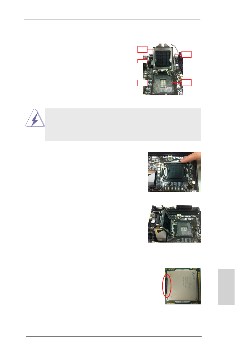
Step 1. Open the socket:
Step 1-1. Disengage the lever by pressing it
down and sliding it out of the hook.
You do not have to remove the protection cover.
Step 1-2. Keep the lever positioned at about
135 degrees in order to flip up the
load plate.
Loa d
Pla te
Cov er
Con tact
Arr ay
1155-Pin Socket Overview
Loa d
Lev er
Soc ket
Bod y
Step 2. Insert the 1155-Pin CPU:
Step 2-1. Hold the CPU by the edge which is
marked with a black line.
Step 2-2. Orient the CPU with the IHS (Inte-
grated Heat Sink) up. Locate Pin1
and the two orientation key notches.
ASRock Z77 OC Formula Motherboard
black line
English
15
Page 16
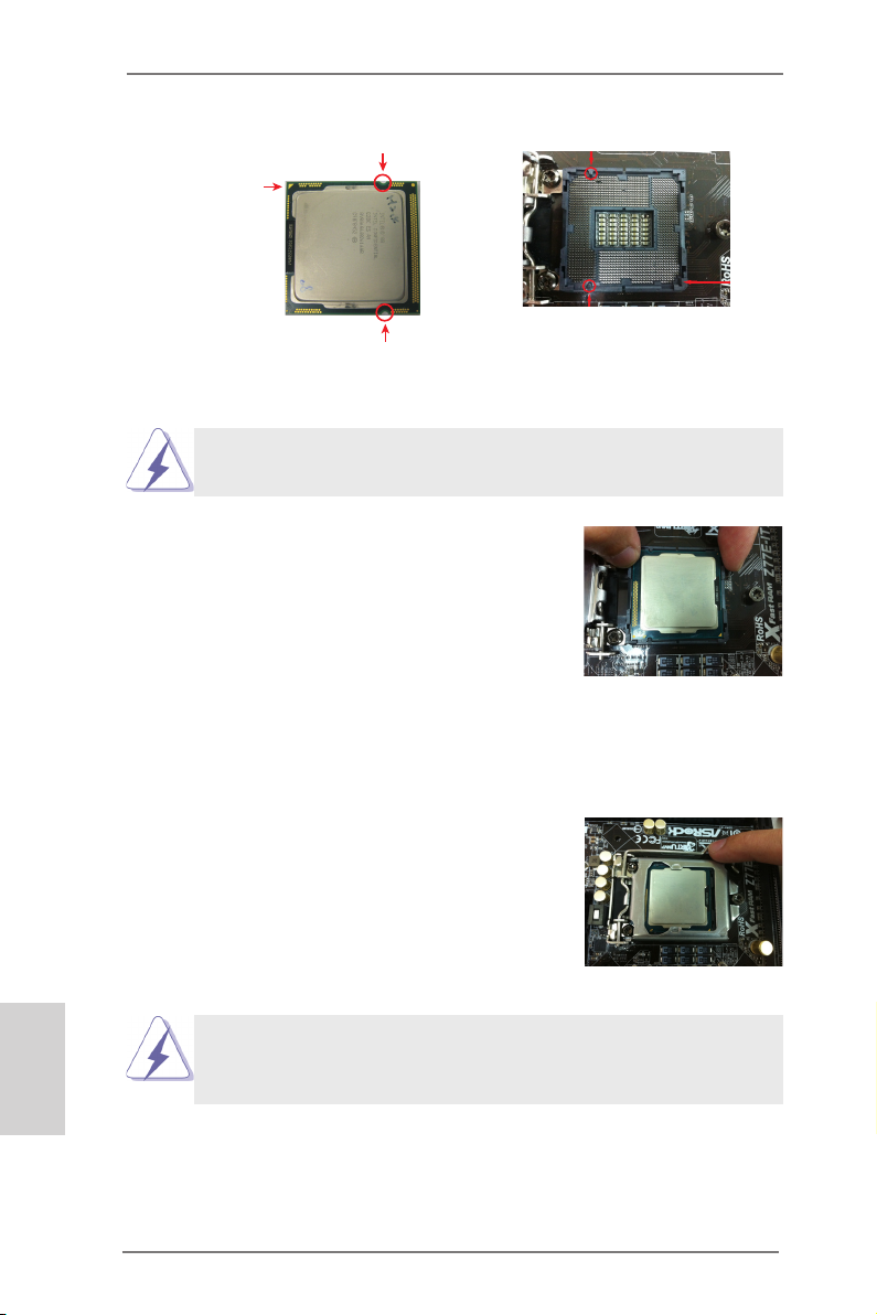
orientation key notch
Pin1
alignment key
Pin1
orientation key notch
1155-Pin CPU
For proper installation, please ensure to match the two orientation
key notches of the CPU with the two alignment keys of the socket.
Step 2-3. Car efully pla ce the CPU into the
socket.
Step 2-4. Verify that the CPU is within the sock-
et and properly mated to the orient
keys.
Step 3. Close the socket:
Step 3-1. Flip the load plate onto the IHS.
Step 3-2. Press down the load lever, and se-
cure it with the load plate tab under
th e r etention ta b. Th e p rotection
cover will automatically come off by
itself.
alignment key
1155-Pin Socket
English
Please save and replace the cover if the processor is removed. The
cover must be placed if you wish to return the motherboard for after
service.
16
ASRock Z77 OC Formula Motherboard
Page 17
2.4 Installation of CPU Fan and Heatsink
Appl yT herma l
Inte rface Ma teria l
Fan ca bles on si de
clos est to MB he ader
Fast ener slo ts
poin ting str aight o ut
Pres s Down
(4 Pla ces)
This motherboard is equipped with 1155-Pin socket that supports Intel 1155-Pin
CPUs. Please adopt the type of heatsink and cooling fan compliant with Intel 1155Pin CPU to dissipate heat. Before you install the heatsink, you need to spray thermal interface material between the CPU and the heatsink to improve heat dissipation. Ensure that the CPU and the heatsink are securely fastened and in good contact with each other. Then connect the CPU fan to the CPU_FAN connector (CPU_
FAN1, see page 2, No. 4 or CPU_FAN2, see page 2, No. 5).
For proper installation, please kindly refer to the instruction manuals of your
CPU fan and heatsink.
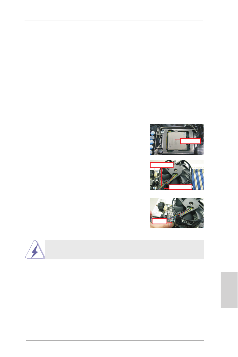
Below is an example to illustrate the installation of the heatsink for 1155-Pin CPUs.
Step 1. Apply thermal interface material onto the cen-
ter of the IHS on the socket’s surface. ASRock
provides the free bundle GELID GC-Extreme
Thermal Compound in the accessory pack.
Step 2. Place the heatsink onto the socket. Ensure
that the fan cables are oriented on side closest
to the CPU fan connector on the motherboard
(CPU_FAN1, see page 2, No. 4 or CPU_
FAN2, see page 2, No. 5).
Step 3. Align fasteners with the motherboard through-
holes.
Step 4. Rotate the fastener clockwise, then press
down on fastener caps with thumb to install
and lock. Repeat with remaining fasteners.
If you press down the fasteners without rotating them clockwise, the
heatsink cannot be secured on the motherboard.
Step 5. Connect fan header with the CPU fan connector on the motherboard.
Step 6. Secure redundant cable with tie-wrap to ensure the cable does not
interfere with fan operation or contact other components.
ASRock Z77 OC Formula Motherboard
English
17
Page 18
English
2.5 Installation of Memory Modules (DIMM)
This motherboard provides four 240-pin DDR3 (Double Data Rate 3) DIMM
slots, and supports Dual Channel Memory Technology. For dual channel conguration, you always need to install identical (the same brand, speed, size
and chip-type) DDR3 DIMM pair in the slots: You have to install identical
DDR3 DIMMs in Dual Channel A (DDR3_A1 and DDR3_B1; Black slots; see p.2
No. 6) or identical DDR3 DIMMs in Dual Channel B (DDR3_A2 and DDR3_
B2; Yellow slots; see p.2 No. 7), so that Dual Channel Memory Technology can
be activated. This motherboard also allows you to install four DDR3 DIMMs
for dual channel conguration, please install identical DDR3 DIMMs in all four
slots. You may refer to the Dual Channel Memory Conguration Table below.
Dual Channel Memory Conguration
DDR3_A1 DDR3_A2 DDR3_B1 DDR3_B2
(Black Slot) (Yellow Slot) (Black Slot) (Yellow Slot)
(1) Populated - Populated (2) - Populated - Populated
(3)* Populated Populated Populated Populated
For conguration (3), please install identical DDR3 DIMMs in all four
*
slots.
1. If you want to install two memory modules, for optimal compatibility
and reliability, it is recommended to install them in the slots: DDR3_
A1 and DDR3_B1, or DDR3_A2 and DDR3_B2.
2. If only one memory module or three memory modules are installed
in the DDR3 DIMM slots on this motherboard, it is unable to activate
Dual Channel Memory Technology.
3. If a pair of memory modules is NOT installed in the same Dual
Cha nnel, for example, installing a pair of memory modules in
DDR3_A1 and DDR3_A2, it is unable to activate Dual Channel
Memory Technology.
4. It is not allowed to install a DDR or DDR2 memory module into
DDR3 slot; otherwise, this motherboard and DIMM may be damaged.
5. Some DDR3 1GB double-sided DIMMs with 16 chips may not work
on this motherboard. It is not recommended to install them on this
motherboard.
6. For optimal compatibility and stability while overclocking memory
frequency, it is recommended to install one memory module on
DDR3_B2 slot or two memory modules on DDR3_A2 and DDR3_
B2 slots.
18
ASRock Z77 OC Formula Motherboard
Page 19
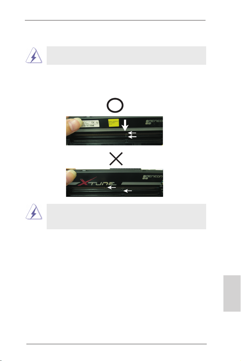
Installing a DIMM
Please make sure to disconnect power supply before adding or
removing DIMMs or the system components.
Step 1. Unlock a DIMM slot by pressing the retaining clips outward.
Step 2. Align a DIMM on the slot such that the notch on the DIMM matches the
break on the slot.
no tch
br eak
no tch
br eak
The DIMM only ts in one correct orientation. It will cause permanent
damage to the motherboard and the DIMM if you force the DIMM into
the slot at incorrect orientation.
Step 3. Firmly insert the DIMM into the slot until the retaining clips at both ends
fully snap back in place and the DIMM is properly seated.
ASRock Z77 OC Formula Motherboard
English
19
Page 20
2.6 Expansion Slots (PCI Express Slots)
There are 5 PCI Express slots on this motherboard.
PCIE slots:
PCIE1 (PCIE 2.0 x1 slot) is used for a PCI Express x1 lane width card,
such as a Gigabit LAN card, SATA2 card, etc.
PCIE2 (PCIE 3.0 x16 slot) is used for PCI Express x16 lane width
graphics cards, or to install PCI Express graphics cards to support
CrossFireXTM or SLITM function.
PCIE3 (PCIE 2.0 x1 slot) is used for a PCI Express x1 lane width card,
such as a Gigabit LAN card or SATA2 card, etc.
PCIE4 (PCIE 3.0 x16 slot) is used for PCI Express x8 lane width graph-
ics cards, or to install PCI Express graphics cards to support CrossFi-
reXTM or SLITM function.
PCIE5 (PCIE 2.0 x16 slot) is used for PCI Express x4 lane width graph-
ics cards.
PCIE Slot Congurations
PCIE1 PCIE2 PCIE3 PCIE4 PCIE5
Single Graphics Card N/A x16 N/A N/A N/A
Two Graphics Cards in N/A x8 N/A x8 N/A
CrossFireXTM or SLITM Mode
Three Graphics Cards in N/A x8 N/A x8 x4
3-Way CrossFireXTM Mode
English
1. In single VGA card mode, it is recommended to install a PCI Express
x16 graphics card in the PCIE2 slot.
2. In CrossFireXTM mode or SLITM mode, please install the PCI Express
x16 graphics cards in PCIE2 and PCIE4 slots. Both these two slots
will work at x8 bandwidth.
3. In 3-Way CrossFireXTM mode, please install the PCI Express x16
graphics cards in PCIE2, PCIE4 and PCIE5 slots. PCIE2 and PCIE4
will work at x8 bandwidth, while PCIE5 works at x4 bandwidth.
4. Please connect a chassis fan to the motherboard’s chassis fan
connector (CHA_FAN1, CHA_FAN2, CHA_FAN3 or CHA_FAN4)
when using multiple graphics cards for better thermal environment.
5. Only PCIE2 and PCIE4 slots support Gen 3 speed. To run the PCI
Express in Gen 3 speed, please install an Ivy Bridge CPU. If you
install a Sandy Bridge CPU, the PCI Express will run only at PCI
Express Gen 2 speed.
6. You can use PCIe ON/OFF Switch to enable and disable the
corresponding PCI Express x16 slots. Please refer to page 45 for
details.
20
ASRock Z77 OC Formula Motherboard
Page 21

Installing an expansion card
Step 1. Before installing an expansion card, please make sure that the power
supply is switched off or the power cord is unplugged. Please read the
documentation of the expansion card and make necessary hardware
settings for the card before you start the installation.
Step 2. Remove the system unit cover (if your motherboard is already installed
in a chassis).
Step 3. Remove the bracket facing the slot that you intend to use. Keep the
screws for later use.
Step 4. Align the card connector with the slot and press rmly until the card is
completely seated on the slot.
Step 5. Fasten the card to the chassis with screws.
Step 6. Replace the system cover.
ASRock Z77 OC Formula Motherboard
English
21
Page 22
2.7 SLITM and Quad SLI
TM
Operation Guide
This motherboard supports NVIDIA® SLITM and Quad SLITM (Scalable Link Interface)
technology that allows you to install up to two identical PCI Express x16 graphics
cards. Currently, NVIDIA® SLITM technology supports Windows® XP / XP 64-bit /
VistaTM / VistaTM 64-bit / 7 / 7 64-bit OS. NVIDIA® Quad SLITM technology support
Windows® VistaTM / VistaTM 64-bit / 7 / 7 64-bit OS only. Please follow the installation
procedures in this section.
Requirements
1. For SLITM technology, you should have two identical SLITM-ready graphics
cards that are NVIDIA® certied. For Quad SLITM technology, you should
have two identical Quad SLITM-ready graphics cards (dual-GPU on each
graphics card) that are NVIDIA® certied.
2. Make sure that your graphics card driver supports NVIDIA® SLITM
technology. Download the driver from NVIDIA® website
(www.nvidia.com).
3. Make sure that your power supply unit (PSU) can provide at least the
minimum power required by your system. It is recommended to use
NVIDIA® certied PSU. Please refer to NVIDIA® website for details.
2.7.1 Graphics Card Setup
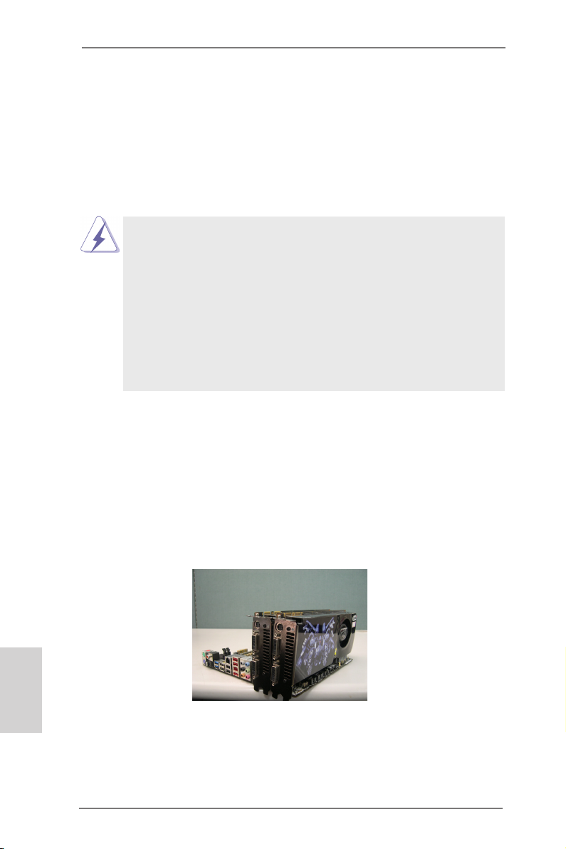
2.7.1.1 Installing Two SLITM-Ready Graphics Cards
Step 1. Install the identical SLITM-ready graphics cards that are NVIDIA® certied
because different types of graphics cards will not work together properly.
(Even the GPU chips version shall be the same.) Insert one graphics card
into PCIE2 slot and the other graphics card to PCIE4 slot. Make sure that
the cards are properly seated on the slots.
English
Step2. If required, connect the auxiliary power source to the PCI Express
graphics cards.
22
ASRock Z77 OC Formula Motherboard
Page 23

Step3. Align and insert the ASRock SLI_Bridge_2S Card to the goldngers on
each graphics card. Make sure the ASRock SLI_Bridge_2S Card is rmly
in place.
ASRock SLI_Bridge_2S Card
Step4. Connect a VGA cable or a DVI cable to the monitor connector or the DVI
connector of the graphics card that is inserted to PCIE2 slot.
ASRock Z77 OC Formula Motherboard
English
23
Page 24

2.7.2 Driver Installation and Setup
Install the graphics card drivers to your system. After that, you can enable the MultiGraphics Processing Unit (GPU) feature in the NVIDIA® nView system tray utility.
Please follow the below procedures to enable the multi-GPU feature.
For Windows® XP / XP 64-bit OS:
(For SLITM mode only)
A. Double-click NVIDIA Settings icon on your Windows® taskbar.
B. From the pop-up menu, select Set SLI and PhysX conguration. In
Set PhysX GPU acceleration item, please select Enabled. In Select
an SLI conguration item, please select Enable SLI. And click Apply.
English
C. Reboot your system.
D. You can freely enjoy the benet of SLITM feature.
24
ASRock Z77 OC Formula Motherboard
Page 25

For Windows® VistaTM / VistaTM 64-bit / 7 / 7 64-bit OS:
(For SLITM and Quad SLITM mode)
A. Click the Start icon on your Windows taskbar.
B. From the pop-up menu, select All Programs, and then click NVIDIA
Corporation.
C. Select NVIDIA Control Panel tab.
D. Select Control Panel tab.
E. From the pop-up menu, select Set SLI and PhysX conguration. In
Set PhysX GPU acceleration item, please select Enabled. In Select
an SLI conguration item, please select Enable SLI. And click Apply.
F. Reboot your system.
G. You can freely enjoy the benet of SLITM or Quad SLITM feature.
* SLITM appearing here is a registered trademark of NVIDIA® Technologies Inc., and is used
only for identication or explanation and to the owners’ benet, without intent to infringe.
ASRock Z77 OC Formula Motherboard
English
25
Page 26
2.8 CrossFireXTM, 3-Way CrossFireXTM and Quad
CrossFireXTM Operation Guide
This motherboard supports CrossFireXTM, 3-way CrossFireX
CrossFireXTM feature. CrossFireXTM technology offers the most advantageous
means available of combining multiple high performance Graphics Processing
Units (GPU) in a single PC. Combining a range of different operating modes with
intelligent software design and an innovative interconnect mechanism, CrossFireXTM
enables the highest possible level of performance and image quality in any 3D
application. Currently CrossFireXTM feature is supported with Windows® XP with
Service Pack 2 / VistaTM / 7 OS. 3-way CrossFireXTM and Quad CrossFireX
are supported with Windows® VistaTM / 7 OS only. Please check AMD website for
ATITM CrossFireXTM driver updates.
1. If a customer incorrectly congures their system they will not see the
performance benets of CrossFireXTM. All three CrossFireXTM components, a
CrossFireXTM Ready graphics card, a CrossFireXTM Ready motherboard and a
CrossFireXTM Edition co-processor graphics card, must be installed correctly to
benet from the CrossFireXTM multi-GPU platform.
2. If you pair a 12-pipe CrossFireXTM Edition card with a 16-pipe card, both cards
will operate as 12-pipe cards while in CrossFireXTM mode.
TM
and Quad
TM
feature
2.8.1 Graphics Card Setup
2.8.1.1 Installing Two CrossFireXTM-Ready Graphics Cards
English
Different CrossFireXTM cards may require different methods to enable CrossFireXTM
feature. For other CrossFireXTM cards that AMD has released or will release in the
future, please refer to AMD graphics card manuals for detailed installation guide.
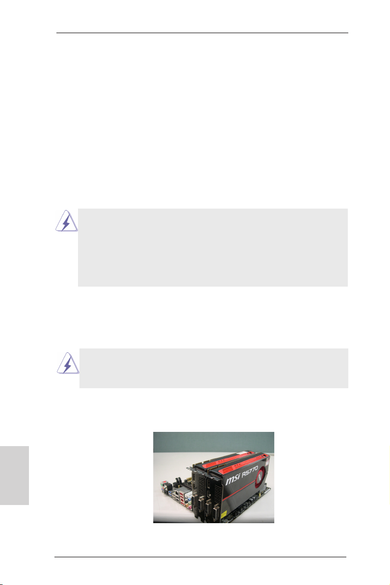
Step 1. Insert one Radeon graphics card into PCIE2 slot and the other Radeon
graphics card to PCIE4 slot. Make sure that the cards are properly seated
on the slots.
26
ASRock Z77 OC Formula Motherboard
Page 27

Step 2. Connect two Radeon graphics cards by installing CrossFire Bridge on
CrossFire Bridge Interconnects on the top of Radeon graphics cards.
(CrossFire Bridge is provided with the graphics card you purchase, not
bundled with this motherboard. Please refer to your graphics card vendor
for details.)
CrossFire Bridge
or
Step 3. Connect the DVI monitor cable to the DVI connector on the Radeon
graphics card on PCIE2 slot. (You may use the DVI to D-Sub adapter to
convert the DVI connector to D-Sub interface, and then connect the D-Sub
monitor cable to the DVI to D-Sub adapter.)
ASRock Z77 OC Formula Motherboard
English
27
Page 28
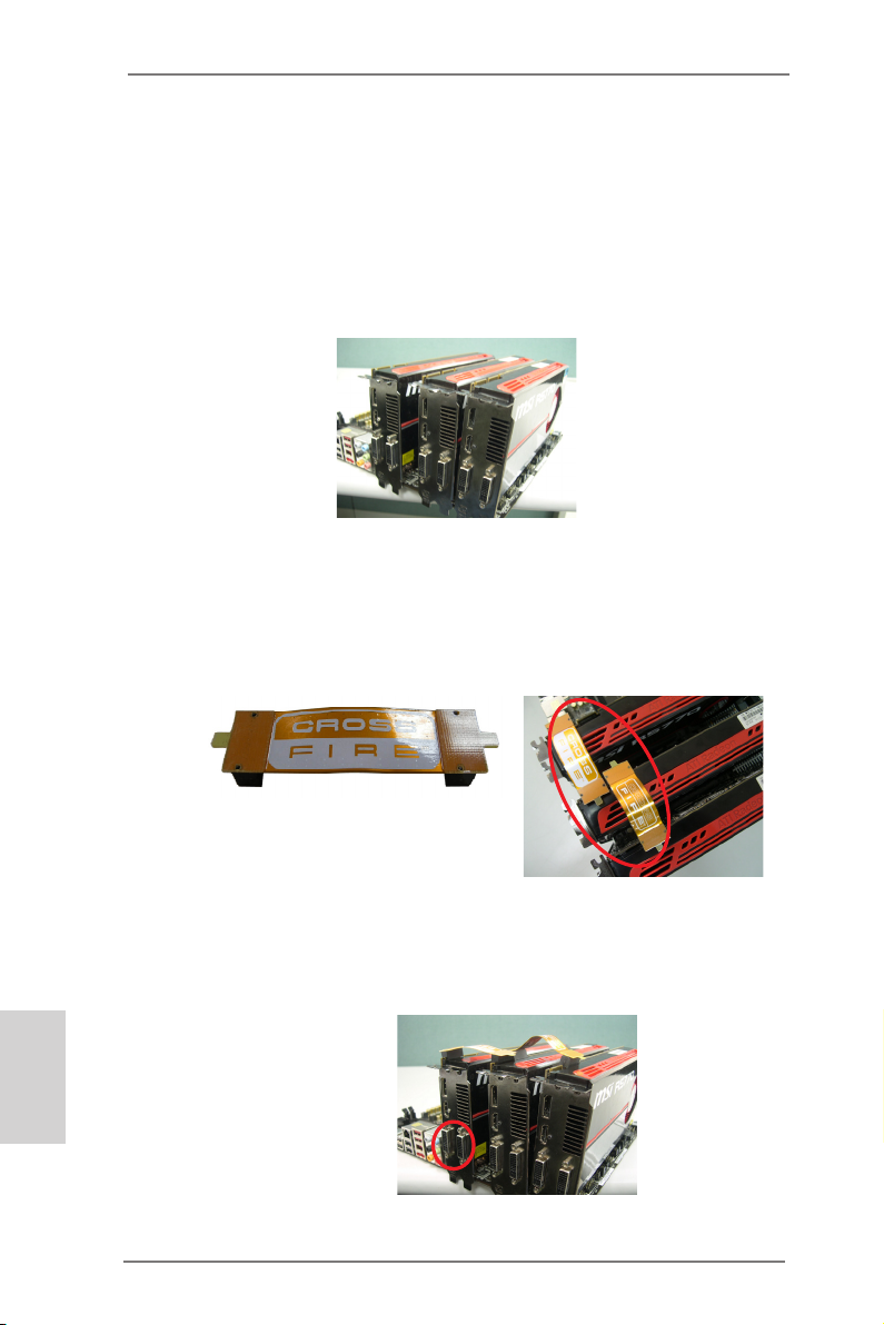
2.8.1.2 Installing Three CrossFireXTM-Ready Graphics Cards
Step 1. Install the identical 3-Way CrossFireXTM-ready graphics cards that are
AMD® certified because different types of graphics cards will not work
together properly. (Even the GPU chips version shall be the same.) Insert
one graphics card into PCIE2 slot, another graphics card to PCIE4 slot,
and the other graphics card to PCIE5 slot. Make sure that the cards are
properly seated on the slots.
Step 2. Use one CrossFireTM Bridge to connect Radeon graphics cards on PCIE2
and PCIE4 slots, and use the other CrossFireTM Bridge to connect Radeon
graphics cards on PCIE4 and PCIE5 slots. (CrossFireTM Bridge is provided
with the graphics card you purchase, not bundled with this motherboard.
Please refer to your graphics card vendor for details.)
English
CrossFireTM Bridge
Step 3. Connect the DVI monitor cable to the DVI connector on the Radeon graph-
ics card on PCIE2 slot. (You may use the DVI to D-Sub adapter to convert
the DVI connector to D-Sub interface, and then connect the D-Sub monitor
cable to the DVI to D-Sub adapter.)
28
ASRock Z77 OC Formula Motherboard
Page 29

2.8.2 Driver Installation and Setup
Step 1. Power on your computer and boot into OS.
Step 2. Remove the ATITM driver if you have any VGA driver installed in your
system.
The Catalyst Uninstaller is an optional download. We recommend using this
utility to uninstall any previously installed Catalyst drivers prior to installation.
Please check AMD website for ATITM driver updates.
Step 3. Install the required drivers to your system.
For Windows® XP OS:
A. ATITM recommends Windows® XP Service Pack 2 or higher to be
installed (If you have Windows® XP Service Pack 2 or higher installed
in your system, there is no need to download it again):
http://www.microsoft.com/windowsxp/sp2/default.mspx
B. You must have Microsoft .NET Framework installed prior to
downloading and installing the CATALYST Control Center. Please
check Microsoft website for details.
For Windows® 7 / VistaTM OS:
Install the CATALYST Control Center. Please check AMD website for de-
tails.
Step 4. Restart your computer.
Step 5. Install the VGA card drivers to your system, and restart your computer.
Then you will nd “ATI Catalyst Control Center” on your Windows® taskbar.
ATI Catalyst Control Center
Step 6. Double-click “ATI Catalyst Control Center”. Click “View”, select “CrossFi-
reXTM”, and then check the item “Enable CrossFireXTM”. Select “2 GPUs”
and click “Apply” (if you install two Radeon graphics cards). Select “3
GPUs” and click “OK” (if you install three Radeon graphics cards).
ASRock Z77 OC Formula Motherboard
English
29
Page 30
Although you have selected the option “Enable CrossFireTM”, the CrossFireXTM
function may not work actually. Your computer will automatically reboot. After
restarting your computer, please conrm whether the option “Enable
CrossFireTM” in “ATI Catalyst Control Center” is selected or not; if not, please
select it again, and then you are able to enjoy the benet of CrossFireX
feature.
TM
Step 7. You can freely enjoy the benet of CrossFireXTM, 3-Way CrossFireXTM or
Quad CrossFireXTM feature.
* CrossFireXTM appearing here is a registered trademark of ATITM Technologies Inc., and is
used only for identication or explanation and to the owners’ benet, without intent to infringe.
* For further information of ATITM CrossFireXTM technology, please check AMD website for
updates and details.
English
30
ASRock Z77 OC Formula Motherboard
Page 31

2.9 Surround Display Feature
This motherboard supports surround display upgrade. With the internal HDMI output
support and external add-on PCI Express VGA cards, you can easily enjoy the ben-
ets of surround display feature.
Please refer to the following steps to set up a surround display environment:
1. Install the PCI Express VGA cards on PCIE2, PCIE4 and PCIE5 slots. Please
refer to page 20 for proper expansion card installation procedures.
2. Connect a HDMI monitor cable to the HDMI port on the I/O panel. Then connect
other monitor cables to the corresponding connectors of the add-on PCI Express
VGA cards on PCIE2, PCIE4 and PCIE5 slots.
HDMI port
3. Boot your system. Press <F2> or <Del> to enter UEFI setup. Enter “Share
Memory” option to adjust the memory capability to [32MB], [64MB], [128MB],
[256MB] or [512MB] to enable the function of HDMI. Please make sure that the
value you select is less than the total capability of the system memory. If you do
not adjust the UEFI setup, the default value of “Share Memory”, [Auto], will
disable HDMI function when an add-on VGA card is inserted to this motherboard.
4. Install the onboard VGA driver and the add-on PCI Express VGA card driver to
your system. If you have installed the drivers already, there is no need to install
them again.
5. Set up a multi-monitor display.
For Windows® XP / XP 64-bit OS:
Right click on desktop, choose “Properties”, and select the “Settings” tab
so that you can adjust the parameters of the multi-monitors according to
the steps below.
A. Click the “Identify” button to display a large number on each monitor.
B. Right-click the display icon in the Display Properties dialog that you
wish to be your primary monitor, and then select “Primary”. When
you use multiple monitors with your card, one monitor will always be
Primary, and all additional monitors will be designated as Secondary.
C. Select the display icon identied by the number 2.
ASRock Z77 OC Formula Motherboard
English
31
Page 32

D. Click “Extend my Windows desktop onto this monitor”.
E. Right-click the display icon and select “Attached”, if necessary.
F. Set the appropriate “Screen Resolution” and “Color Quality” for the
second monitor. Click “Apply” or “OK” to apply these new values.
G. Repeat steps C through E for the display icon identied by the
numbers three to seven.
For Windows® 7 / 7 64-bit / VistaTM / VistaTM 64-bit OS:
Right click the desktop, choose “Personalize”, and select the “Display
Settings” tab so that you can adjust the parameters of the multi-monitors
according to the steps below.
A. Click the number ”2” icon.
B. Click the items “This is my main monitor” and “Extend the desktop onto
this monitor”.
C. Click “OK” to save your change.
D. Repeat steps A through C for the display icons identied by the number
three to seven.
6. Use Surround Display. Click and drag the display icons to positions representing
the physical setup of your monitors that you would like to use. The placement of
display icons determines how you move items from one monitor to another.
English
32
ASRock Z77 OC Formula Motherboard
Page 33

HDCP Function
HDCP function is supported on this motherboard. To use HDCP
function with this motherboard, you need to adopt a monitor
that supports HDCP function as well. Therefore, you can enjoy
the superior display quality with high-denition HDCP
encryption contents. Please refer to the instructions below for
more details about HDCP function.
What is HDCP?
HDCP stands for High-Bandwidth Digital Content Protection, a
specication developed by Intel® for protecting digital
entertainment content that uses the HDMI interface. HDCP is a
copy protection scheme to eliminate the possibility of
intercepting digital data midstream between the video source,
or transmitter - such as a computer, DVD player or set-top box -
and the digital display, or receiver - such as a monitor, television
or projector. In other words, HDCP specication is designed to
protect the integrity of content as it is being transmitted.
Products compatible with the HDCP scheme such as DVD
players, satellite and cable HDTV set-top-boxes, as well as few
entertainment PCs requires a secure connection to a compliant
display. Due to the increase in manufacturers employing HDCP
in their equipment, it is highly recommended that the HDTV or
LCD monitor you purchase is compatible.
ASRock Z77 OC Formula Motherboard
English
33
Page 34
2.10 ASRock Smart Remote Installation Guide
ASRock Smart Remote is only used for ASRock motherboard with CIR header.
Please refer to below procedures for the quick installation and usage of ASRock
Smart Remote.
Step1. Find the CIR header located next
to the USB 2.0 header on ASRock
motherboard.
USB 2.0 header (9-pin, black)
CIR header (4-pin, gray)
English
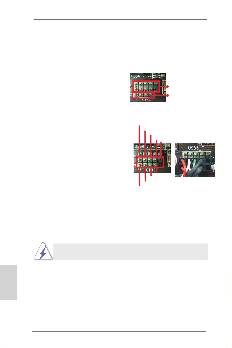
Step2. Connect the front USB cable to the
USB 2.0 header (as below, pin 1-5)
and the CIR header. Please make
USB_PWR
P-
P+
GND
DUMMY
sure the wire assignments and the
pin assignments are matched
correctly.
1
ATX+5VSB
2
IRRX
3
IRTX
GND
5
4
Step3. Install Multi-Angle CIR Receiver to the front USB port.
Step4. Boot up your system. Press <F2> or <Del> to enter BIOS Setup Utility.
Make sure the option "CIR Controller" is setting at [Enabled].
(Advanced -> Super IO Conguration -> CIR Controller -> [Enabled])
If you cannot nd this option, please shut down your system and install
Multi-Angle CIR Receiver to the other front USB port then try again.
Step5. Enter Windows. Execute ASRock support CD and install CIR Driver. (It is
listed at the bottom of driver list.)
34
ASRock Z77 OC Formula Motherboard
Page 35
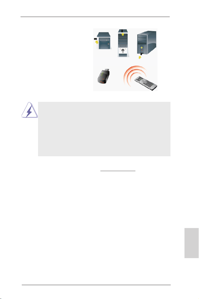
3 CIR sensors in different angles
1. Only one of the front USB port can support CIR function. When
the CIR function is enabled, the other port will remain USB
function.
2. Multi-Angle CIR Receiver is used for front USB only. Please do
not use the rear USB bracket to connect it on the rear panel.
Multi-Angle CIR Receiver can receive the multi-direction infrared
signals (top, down and front), which is compatible with most of
the chassis on the market.
3. The Multi-Angle CIR Receiver does not support Hot-Plug
function. Please install it before you boot the system.
* ASRock Smart Remote is only supported by some of ASRock motherboards. Please refer to
ASRock website for the motherboard support list: http://www.asrock.com
ASRock Z77 OC Formula Motherboard
English
35
Page 36
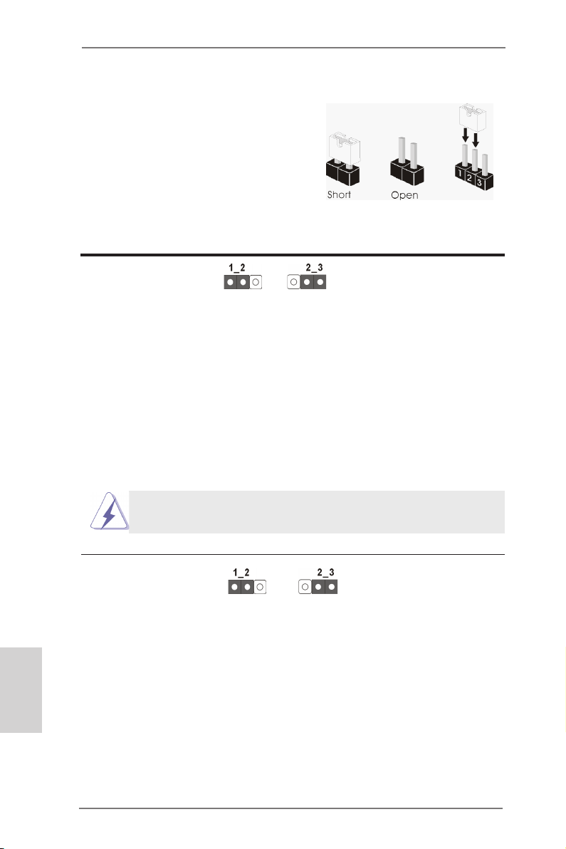
2.11 Jumpers Setup
The illustration shows how jumpers are
setup. When the jumper cap is placed on
pins, the jumper is “Short”. If no jumper cap
is placed on pins, the jumper is “Open”. The
illustration shows a 3-pin jumper whose
pin1 and pin2 are “Short” when jumper cap
is placed on these 2 pins.
Jumper Setting Description
Clear CMOS Jumper
(CLRCMOS1)
(see p.2, No. 46)
Note: CLRCMOS1 allows you to clear the data in CMOS. To clear and reset the
system parameters to default setup, please turn off the computer and unplug
the power cord from the power supply. After waiting for 15 seconds, use a
jumper cap to short pin2 and pin3 on CLRCMOS1 for 5 seconds. However,
please do not clear the CMOS right after you update the BIOS. If you need
to clear the CMOS when you just nish updating the BIOS, you must boot
up the system rst, and then shut it down before you do the clear-CMOS action. Please be noted that the password, date, time, user default prole, 1394
GUID and MAC address will be cleared only if the CMOS battery is removed.
The Clear CMOS Switch has the same function as the Clear CMOS
jumper.
Clear CMOSDefault
English
BIOS Selection Jumper
(BIOS_SEL1)
(see p.2, No. 32)
(Main BIOS)
Backup BIOSDefault
Note: This motherboard has two BIOS onboard, a main BIOS and a backup BIOS,
which enhances protection for the safety and stability of your system. Normally, the system works on the main BIOS. However, if the main BIOS is
corrupted or damaged, please use a jumper cap to short pin2 and pin3, then
the backup BIOS will take over on the next system boot. After that, short pin1
and pin2 again, then use “ASRock Instant Flash“ or “ASRock Internet Flash“
in BIOS setup utility to copy the BIOS le to the main BIOS to ensure normal
system operation. For the sake of system safety, users cannot update the
backup BIOS manually.
36
ASRock Z77 OC Formula Motherboard
Page 37
2.12 Onboard Headers and Connectors
Onboard headers and connectors are NOT jumpers. Do NOT place
jumper caps over these headers and connectors. Placing jumper caps
over the headers and connectors will cause permanent damage of the
motherboard!
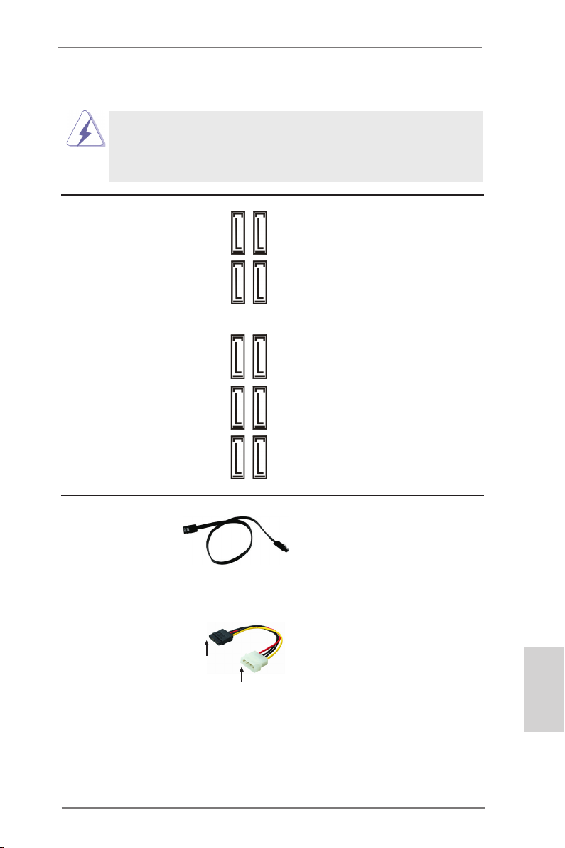
Serial ATA2 Connectors These four Serial ATA2 (SATA2)
(SATA2_2_3: see p.2, No. 19)
(SATA2_4_5: see p.2, No. 18)
devices. The current SATA2
interface allows up to 3.0 Gb/s
data transfer rate.
Serial ATA3 Connectors These six Serial ATA3 (SATA3)
(SATA3_0_1: see p.2, No. 20)
(SATA3_M0_M1: see p.2, No. 21)
(SATA3_M2_M3: see p.2, No. 22)
interface allows up to 6.0 Gb/s
data transfer rate.
connectors support SATA data
cables for internal storage
SATA2_4
SATA2_2
SATA2_5
SATA2_3
connectors support SATA data
cables for internal storage
SATA3_0
devices. The current SATA3
SATA3_M0
SATA3_1
SATA3_M1
SATA3_M2
SATA3_M3
Serial ATA (SATA) Either end of the SATA data
Data Cable cable can be connected to the
(Optional)
SATA / SATA2 / SATA3 hard
disk or the SATA2 / SATA3
connector on this motherboard.
Serial ATA (SATA) Please connect the black end
Power Cable of SATA power cable to the
(Optional)
Then connect the white end of
SATA power cable to the power
connector of the power supply.
power connector on each drive.
connect to the SATA
HDD power connector
connect to the
power supply
ASRock Z77 OC Formula Motherboard
English
37
Page 38
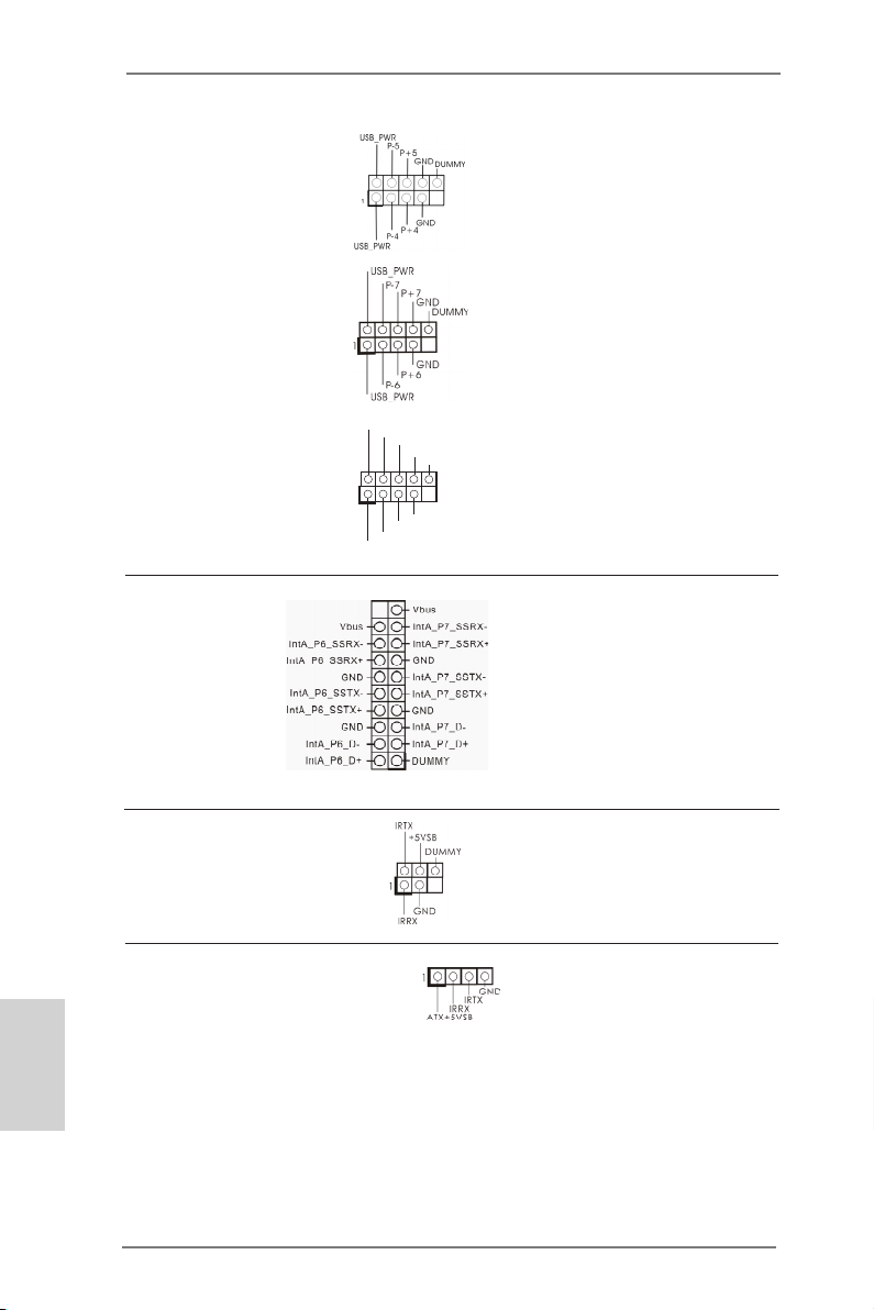
USB 2.0 Headers Besides four default USB 2.0
(9-pin USB4_5)
(see p.2, No. 31)
ports on the I/O panel, there are
three USB 2.0 headers on this
motherboard. Each USB 2.0
header can support two USB 2.0
(9-pin USB6_7)
(see p.2, No. 34)
ports.
English
(9-pin USB8_9)
(see p.2, No. 35)
1
USB _PWR
P-9
P-8
USB _PWR
P+9
P+8
GND
GND
DUM MY
USB 3.0 Header Besides six default USB 3.0
(19-pin USB3_6_7)
(see p.2, No. 15)
ports on the I/O panel, there is
one USB 3.0 header on this
motherboard. This USB 3.0
header can support two USB 3.0
ports.
Infrared Module Header This header supports an
(5-pin IR1)
optional wireless transmitting
(see p.2, No. 38)
and receiving infrared module.
Consumer Infrared Module Header This header can be used to
(4-pin CIR1)
(see p.2 No. 36)
connect the remote
controller receiver.
38
ASRock Z77 OC Formula Motherboard
Page 39
Front Panel Audio Header This is an interface for front
(9-pin HD_AUDIO1)
(see p.2, No. 41)
panel audio cable that allows
convenient connection and
control of audio devices.
1
GND
PRE SENC E#
MIC 2_R
MIC 2_L
MIC _RET
J_S ENSE
OUT 2_R
OUT _RET
OUT 2_L
1. High Denition Audio supports Jack Sensing, but the panel wire on the
chassis must support HDA to function correctly. Please follow the
instruction in our manual and chassis manual to install your system.
2. If you use AC’97 audio panel, please install it to the front panel audio
header as below:
A. Connect Mic_IN (MIC) to MIC2_L.
B. Connect Audio_R (RIN) to OUT2_R and Audio_L (LIN) to OUT2_L.
C. Connect Ground (GND) to Ground (GND).
D. MIC_RET and OUT_RET are for HD audio panel only. You don’t need
to connect them for AC’97 audio panel.
E. To activate the front mic.
For Windows® XP / XP 64-bit OS:
Select “Mixer”. Select “Recorder”. Then click “FrontMic”.
For Windows® 7 / 7 64-bit / VistaTM / VistaTM 64-bit OS:
Go to the “FrontMic” Tab in the Realtek Control panel. Adjust
“Recording Volume”.
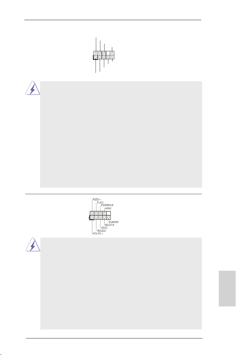
System Panel Header This header accommodates
(9-pin PANEL1)
(see p.2, No. 25)
several system front panel
functions.
Connect the power switch, reset switch and system status indicator on the
chassis to this header according to the pin assignments below. Note the
positive and negative pins before connecting the cables.
PWRBTN (Power Switch):
Connect to the power switch on the chassis front panel. You may congure
the way to turn off your system using the power switch.
RESET (Reset Switch):
Connect to the reset switch on the chassis front panel. Press the reset
switch to restart the computer if the computer freezes and fails to perform a
normal restart.
PLED (System Power LED):
Connect to the power status indicator on the chassis front panel. The LED
is on when the system is operating. The LED keeps blinking when the
ASRock Z77 OC Formula Motherboard
English
39
Page 40
system is in S1/S3 sleep state. The LED is off when the system is in S4
sleep state or powered off (S5).
HDLED (Hard Drive Activity LED):
Connect to the hard drive activity LED on the chassis front panel. The LED
is on when the hard drive is reading or writing data.
The front panel design may differ by chassis. A front panel module mainly
consists of power switch, reset switch, power LED, hard drive activity LED,
speaker and etc. When connecting your chassis front panel module to this
header, make sure the wire assignments and the pin assign-ments are
matched correctly.
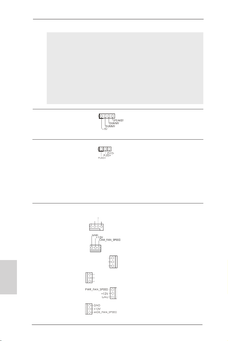
Chassis Speaker Header Please connect the chassis
(4-pin SPEAKER 1)
(see p.2, No. 23)
speaker to this header.
Power LED Header Please connect the chassis
(3-pin PLED1)
(see p.2, No. 24)
power LED to this header to
indicate system power status.
The LED is on when the system
is operating. The LED keeps
blinking in S1/S3 state. The
LED is off in S4 state or S5
state (power off).
English
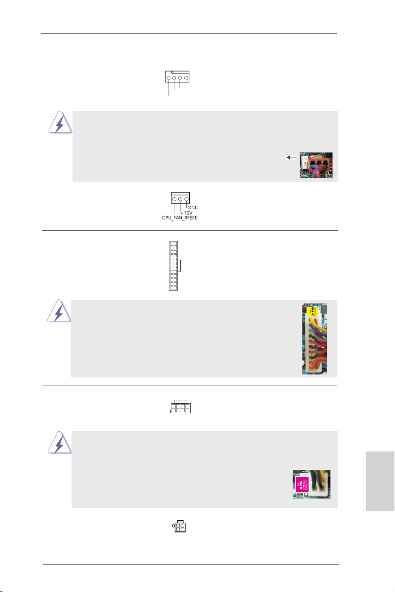
Chassis, Power and MOS Fan Please connect the fan cables
Connectors to the fan connectors and match
(4-pin CHA_FAN1)
(see p.2, No. 37)
the black wire to the ground pin.
CHA _FAN _SPE ED
+12 V
FAN _SPE ED_C ONTR OL
GND
(3-pin CHA_FAN2)
(see p.2, No. 33)
(3-pin CHA_FAN3)
(see p.2, No. 17)
(3-pin CHA_FAN4)
(see p.2, No. 49)
(3-pin PWR_FAN1)
(see p.2, No. 16)
(3-pin MOS_FAN1)
(see p.2, No. 50)
CHA _FAN _SP EED
+12 V
GND
GND
+12 V
CHA _FAN_ SPEE D
40
ASRock Z77 OC Formula Motherboard
Page 41
CPU Fan Connectors Please connect the CPU fan
(4-pin CPU_FAN1)
(see p.2, No. 4)
cable to the connector and
match the black wire to the
ground pin.
4 3 2 1
+12 V
FAN_ SPEE D_CO NTRO L
CPU _FAN_ SPEE D
GND
Though this motherboard provides 4-Pin CPU fan (Quiet Fan) support, the 3-Pin
CPU fan still can work successfully even without the fan speed control function.
If you plan to connect the 3-Pin CPU fan to the CPU fan connector on this
motherboard, please connect it to Pin 1-3.
(3-pin CPU_FAN2)
(see p.2, No. 5)
Pin 1-3 Connected
3-Pin Fan Installation
ATX Power Connector Please connect an ATX power
(24-pin ATXPWR1)
(see p.2, No. 14)
supply to this connector.
Though this motherboard provides 24-pin ATX power connector,
12 124
13
12
it can still work if you adopt a traditional 20-pin ATX power supply.
To use the 20-pin ATX power supply, please plug your
power supply along with Pin 1 and Pin 13.
20-Pin ATX Power Supply Installation
ATX 12V Power Connectors Please connect the ATX 12V
(8-pin ATX12V1)
(see p.2, No. 2)
power supplies to the
connectors.
8 5
4 1
1
Though this motherboard provides 8-pin ATX 12V power connector, it can still work
if you adopt a traditional 4-pin ATX 12V power supply. To use the 4-pin ATX power
(4-pin ATX12V2)
(see p.2, No. 1)
supply, please plug your power supply along with Pin 1 and Pin 5.
4-Pin ATX 12V Power Supply Installation
8 5
4 1
24
13
English
ASRock Z77 OC Formula Motherboard
41
Page 42

SLI/XFIRE Power Connector It is not necessary to use this
(4-pin SLI/XFIRE_PWR1)
(see p.2 No. 39)
connector, but please connect it
with a hard disk power
SLI/XFIRE_POWER1
connecor when two graphics
cards are plugged to this
motherboard.
Serial port Header This COM1 header supports a
(9-pin COM1)
(see p.2, No. 40)
serial port module.
EnglishEnglish
HDMI_SPDIF Header HDMI_SPDIF header, providing
(2-pin HDMI_SPDIF1)
(see p.2, No. 42)
SPDIF audio output to HDMI
VGA card, allows the system to
1
SPD I FOUT
GND
connect HDMI Digital TV/
projector/LCD devices. Please
connect the HDMI_SPDIF
connector of HDMI VGA card to
this header.
V-ProbeTM Users are able to measure
(7-pin VOL_CON1,
7-pin VOL_CON2)
(see p.2, No. 13)
VTT2, VTT1, VCORE,
onboard components voltage,
including VCCM, VCCSA,
DMI_COMP, XCLK_RCOMP,
DMI, PCH2, PCH and
1.8V_PLL.
VCCM: DRAM voltage
VCCSA: CPU system agent voltage
VTT2: Main VTT voltage
VTT1: 2nd VTT voltage
VCORE: CPU core voltage
DMI_COMP: DMI COMP voltage
XCLK_RCOMP: Internal clock gen COMP voltage
DMI: DMI voltage
PCH2: Chipset core voltage
PCH: 2nd chipset core voltage
1.8V_PLL: CPU PLL voltage
42
ASRock Z77 OC Formula Motherboard
Page 43

The Installation Guide of Front USB 3.0 Panel
Step 1
Prepare the bundled Front USB 3.0 Panel, four
HDD screws, and six chassis screws.
Step 2
Screw the 2.5” HDD/SSD to the Front
USB 3.0 Panel with four HDD screws.
Step 3
Intall the Front USB 3.0 Panel into the 2.5”
drive bay of the chassis.
Step 5
Plug the Front USB 3.0 cable into the USB 3.0
header (USB3_6_7) on the motherboard.
Step 4
Step 6
The Installation Guide of Rear USB 3.0 Bracket
Step 1
Unscrew the two screws from the Front USB 3.0
Panel.
Step 2
Screw the Front USB 3.0 Panel to the
drive bay with six chassis screws.
The Front USB 3.0 Panel is ready to use.
Put the USB 3.0 cable and the rear
USB 3.0 bracket together.
Step 3
Screw the two screws into the rear USB 3.0
bracket.
ASRock Z77 OC Formula Motherboard
Step 4
Put the rear USB 3.0 bracket into the
chassis.
English
43
Page 44

2.13 Smart Switches
The motherboard has six smart switches: power switch, reset switch and clear
CMOS switch, allowing users to quickly turn on/off or reset the system clear the
CMOS values; + / - rapid OC buttons, allowing users to quickly and easily adjust OC
frequency; PCIe ON/OFF, providing users with three switches to enable or disable
the PCIE slots with a single click.
Power Switch Power Switch is a smart switch,
(PWRBTN)
(see p.2 No. 27)
Reset Switch Reset Switch is a smart switch,
(RSTBTN)
(see p.2 No. 28)
Clear CMOS Switch Clear CMOS Switch is a smart
(CLRCBTN)
(see p.3 No. 14)
+ / - Rapid OC Buttons + / - Rapid OC Buttons allow
(MINUS1: see p.2 No. 10)
(PLUS1: see p.2 No. 11)
OC.
allowing users to quickly turn
Pow er
on/off the system.
allowing users to quickly reset
Res et
the system.
switch, allowing users to quickly
clear the CMOS values.
users to quickly and easily
adjust OC frequency in Rapid
English
This overclocking behavior depends on the system conguration, such as
memory capability, thermal solution, etc. Overclocking may affect your system
stability, or even cause damage to the components and devices. We are not
responsible for possible damage caused by overclocking.
44
ASRock Z77 OC Formula Motherboard
Page 45

PCIe ON/OFF Switch PCIe ON/OFF Switch allows
(SWITCH1)
(see p.2 No. 9)
you to enable and disable the
corresponding PCIE x16 slots.
When one of the installed PCIE
1: PCIE2
2: PCIE4
3: PCIE5
x16 cards is out of order, you
can use PCIe ON/OFF Switch
to nd out the faulty one just
with a single click without
removing the cards.
1. Make sure that you power off the system before changing the switch.
2. When you turn off PCIe ON/OFF switch, your PCIE card could be burnt if
it was poorly designed. For more information about your card’s
specications please contact the card’s vendor.
3. PCIe ON/OFF switch is for debug only. If you do not want to use your PCIE
card, please remove it from the motherboard.
ASRock Z77 OC Formula Motherboard
English
45
Page 46

English
2.14 Dr. Debug
Dr. Debug is used to provide code information, which makes troubleshooting even
easier. Please see the diagrams below for reading the Dr. Debug codes.
Status Code Description
0x00 Not used
0x01 Power on. Reset type detection (soft/hard)
0x02 AP initialization before microcode loading
0x03 North Bridge initialization before microcode loading
0x04 South Bridge initialization before microcode loading
0x05 OEM initialization before microcode loading
0x06 Microcode loading
0x07 AP initialization after microcode loading
0x08 North Bridge initialization after microcode loading
0x09 South Bridge initialization after microcode loading
0x0A OEM initialization after microcode loading
0x0B Cache initialization
0x0C – 0x0D Reserved for future AMI SEC error codes
0x0E Microcode not found
0x0F Microcode not loaded
0x10 PEI Core is started
0x11 Pre-memory CPU initialization is started
0x12 Pre-memory CPU initialization (CPU module specic)
0x13 Pre-memory CPU initialization (CPU module specic)
0x14 Pre-memory CPU initialization (CPU module specic)
0x15 Pre-memory North Bridge initialization is started
0x16 Pre-Memory North Bridge initialization (North Bridge module specic)
0x17 Pre-Memory North Bridge initialization (North Bridge module specic)
0x18 Pre-Memory North Bridge initialization (North Bridge module specic)
0x19 Pre-memory South Bridge initialization is started
0x1A Pre-memory South Bridge initialization (South Bridge module specic)
0x1B Pre-memory South Bridge initialization (South Bridge module specic)
0x1C Pre-memory South Bridge initialization (South Bridge module specic)
0x1D – 0x2A OEM pre-memory initialization codes
0x2B Memory initialization. Serial Presence Detect (SPD) data reading
0x2C Memory initialization. Memory presence detection
0x2D Memory initialization. Programming memory timing information
0x2E Memory initialization. Conguring memory
0x2F Memory initialization (other)
0x30 Reserved for ASL
0x31 Memory Installed
0x32 CPU post-memory initialization is started
0x33 CPU post-memory initialization. Cache initialization
0x34 CPU post-memory initialization. Application Processor(s) (AP) initialization
0x35 CPU post-memory initialization. Boot Strap Processor (BSP) selection
0x36 CPU post-memory initialization. System Management Mode (SMM)
initialization
46
ASRock Z77 OC Formula Motherboard
Page 47

0x37 Post-Memory North Bridge initialization is started
0x38 Post-Memory North Bridge initialization (North Bridge module specic)
0x39 Post-Memory North Bridge initialization (North Bridge module specic)
0x3A Post-Memory North Bridge initialization (North Bridge module specic)
0x3B Post-Memory South Bridge initialization is started
0x3C Post-Memory South Bridge initialization (South Bridge module specic)
0x3D Post-Memory South Bridge initialization (South Bridge module specic)
0x3E Post-Memory South Bridge initialization (South Bridge module specic)
0x3F-0x4E OEM post memory initialization codes
0x4F DXE IPL is started
0x50 Memory initialization error. Invalid memory type or incompatible memory
speed
0x51 Memory initialization error. SPD reading has failed
0x52 Memory initialization error. Invalid memory size or memory modules do not
match
0x53 Memory initialization error. No usable memory detected
0x54 Unspecied memory initialization error
0x55 Memory not installed
0x56 Invalid CPU type or Speed
0x57 CPU mismatch
0x58 CPU self test failed or possible CPU cache error
0x59 CPU micro-code is not found or micro-code update is failed
0x5A Internal CPU error
0x5B reset PPI is not available
0x5C-0x5F Reserved for future AMI error codes
0xE0 S3 Resume is stared (S3 Resume PPI is called by the DXE IPL)
0xE1 S3 Boot Script execution
0xE2 Video repost
0xE3 OS S3 wake vector call
0xE4-0xE7 Reserved for future AMI progress codes
0xE8 S3 Resume Failed
0xE9 S3 Resume PPI not Found
0xEA S3 Resume Boot Script Error
0xEB S3 OS Wake Error
0xEC-0xEF Reserved for future AMI error codes
0xF0 Recovery condition triggered by rmware (Auto recovery)
0xF1 Recovery condition triggered by user (Forced recovery)
0xF2 Recovery process started
0xF3 Recovery rmware image is found
0xF4 Recovery rmware image is loaded
0xF5-0xF7 Reserved for future AMI progress codes
0xF8 Recovery PPI is not available
0xF9 Recovery capsule is not found
0xFA Invalid recovery capsule
0xFB – 0xFF Reserved for future AMI error codes
0x60 DXE Core is started
0x61 NVRAM initialization
English
ASRock Z77 OC Formula Motherboard
47
Page 48

English
0x62 Installation of the South Bridge Runtime Services
0x63 CPU DXE initialization is started
0x64 CPU DXE initialization (CPU module specic)
0x65 CPU DXE initialization (CPU module specic)
0x66 CPU DXE initialization (CPU module specic)
0x67 CPU DXE initialization (CPU module specic)
0x68 PCI host bridge initialization
0x69 North Bridge DXE initialization is started
0x6A North Bridge DXE SMM initialization is started
0x6B North Bridge DXE initialization (North Bridge module specic)
0x6C North Bridge DXE initialization (North Bridge module specic)
0x6D North Bridge DXE initialization (North Bridge module specic)
0x6E North Bridge DXE initialization (North Bridge module specic)
0x6F North Bridge DXE initialization (North Bridge module specic)
0x70 South Bridge DXE initialization is started
0x71 South Bridge DXE SMM initialization is started
0x72 South Bridge devices initialization
0x73 South Bridge DXE Initialization (South Bridge module specic)
0x74 South Bridge DXE Initialization (South Bridge module specic)
0x75 South Bridge DXE Initialization (South Bridge module specic)
0x76 South Bridge DXE Initialization (South Bridge module specic)
0x77 South Bridge DXE Initialization (South Bridge module specic)
0x78 ACPI module initialization
0x79 CSM initialization
0x7A – 0x7F Reserved for future AMI DXE codes
0x80 – 0x8F OEM DXE initialization codes
0x90 Boot Device Selection (BDS) phase is started
0x91 Driver connecting is started
0x92 PCI Bus initialization is started
0x93 PCI Bus Hot Plug Controller Initialization
0x94 PCI Bus Enumeration
0x95 PCI Bus Request Resources
0x96 PCI Bus Assign Resources
0x97 Console Output devices connect
0x98 Console input devices connect
0x99 Super IO Initialization
0x9A USB initialization is started
0x9B USB Reset
0x9C USB Detect
0x9D USB Enable
0x9E – 0x9F Reserved for future AMI codes
0xA0 IDE initialization is started
0xA1 IDE Reset
0xA2 IDE Detect
0xA3 IDE Enable
0xA4 SCSI initialization is started
0xA5 SCSI Reset
48
ASRock Z77 OC Formula Motherboard
Page 49

0xA6 SCSI Detect
0xA7 SCSI Enable
0xA8 Setup Verifying Password
0xA9 Start of Setup
0xAA Reserved for ASL (see ASL Status Codes section below)
0xAB Setup Input Wait
0xAC Reserved for ASL (see ASL Status Codes section below)
0xAD Ready To Boot event
0xAE Legacy Boot event
0xAF Exit Boot Services event
0xB0 Runtime Set Virtual Address MAP Begin
0xB1 Runtime Set Virtual Address MAP End
0xB2 Legacy Option ROM Initialization
0xB3 System Reset
0xB4 USB hot plug
0xB5 PCI bus hot plug
0xB6 Clean-up of NVRAM
0xB7 Conguration Reset (reset of NVRAM settings)
0xB8 – 0xBF Reserved for future AMI codes
0xC0 – 0xCF OEM BDS initialization codes
0xD0 CPU initialization error
0xD1 North Bridge initialization error
0xD2 South Bridge initialization error
0xD3 Some of the Architectural Protocols are not available
0xD4 PCI resource allocation error. Out of Resources
0xD5 No Space for Legacy Option ROM
0xD6 No Console Output Devices are found
0xD7 No Console Input Devices are found
0xD8 Invalid password
0xD9 Error loading Boot Option (LoadImage returned error)
0xDA Boot Option is failed (StartImage returned error)
0xDB Flash update is failed
0xDC Reset protocol is not available
ASRock Z77 OC Formula Motherboard
English
49
Page 50
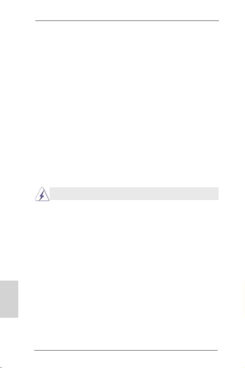
2.15 Post Status Checker (PSC)
Post Status Checker (PSC) diagnoses the computer when users power on the machine. It emits a red light to indicate whether the CPU, memory, VGA or storage is
dysfunctional. The lights go off if the four mentioned above are functioning normally.
2.16 Driver Installation Guide
To install the drivers to your system, please insert the support CD to your optical
drive rst. Then, the drivers compatible to your system can be auto-detected and
listed on the support CD driver page. Please follow the order from up to bottom side
to install those required drivers. Therefore, the drivers you install can work properly.
English
2.17 Installing Windows® 7 / 7 64-bit / Vista
TM
/ VistaTM 64-bit With
RAID Functions
If you want to install Windows® 7 / 7 64-bit / VistaTM / VistaTM 64-bit on your SATA
/ SATA2 / SATA3 HDDs with RAID functions, please refer to the document at the
following path in the Support CD for detailed procedures:
..\ RAID Installation Guide
RAID mode is not supported under Windows® XP / XP 64-bit.
50
ASRock Z77 OC Formula Motherboard
Page 51
2.18 Installing Windows® 7 / 7 64-bit / Vista
TM
/ Vista
TM
64-bit / XP /
XP 64-bit Without RAID Functions
If you want to install Windows® 7 / 7 64-bit / VistaTM / VistaTM 64-bit / XP / XP 64bit OS on your SATA / SATA2 / SATA3 HDDs without RAID functions, please follow
below procedures according to the OS you install.
2.18.1 Installing Windows® XP / XP 64-bit Without RAID Functions
If you want to install Windows® XP / XP 64-bit OS on your SATA / SATA2 / SATA3
HDDs without RAID functions, please follow below steps.
AHCI mode is not supported under Windows® XP / XP 64-bit.
Using SATA / SATA2 / SATA3 HDDs without NCQ function
STEP 1: Set Up UEFI.
A. Enter UEFI SETUP UTILITY Advanced screen Storage Conguration.
B. Set the option “SATA Mode Selection” to [IDE] for SATA2_2 to SATA2_5 and
SATA3_0 and SATA3_1 ports.
Set the option “Marvell SATA3 M0 M1 Operation Mode” to [IDE] for SATA3_M0
and SATA3_M1 ports.
Set the option “Marvell SATA3 M2 M3 Operation Mode” to [IDE] for SATA3_M2
and SATA3_M3 ports.
STEP 2: Install Windows® XP / XP 64-bit OS on your system.
ASRock Z77 OC Formula Motherboard
English
51
Page 52

2.18.2 Installing Windows® 7 / 7 64-bit / Vista
TM
/ Vista
TM
64-bit
Without RAID Functions
If you want to install Windows® 7 / 7 64-bit / VistaTM / VistaTM 64-bit OS on your SATA
/ SATA2 / SATA3 HDDs without RAID functions, please follow below steps.
Using SATA / SATA2 / SATA3 HDDs without NCQ function
STEP 1: Set Up UEFI.
A. Enter UEFI SETUP UTILITY Advanced screen Storage Conguration.
B. Set the option “SATA Mode Selection” to [IDE] for SATA2_2 to SATA2_5 and
SATA3_0 and SATA3_1 ports.
Set the option “Marvell SATA3 M0 M1 Operation Mode” to [IDE] for SATA3_M0
and SATA3_M1 ports.
Set the option “Marvell SATA3 M2 M3 Operation Mode” to [IDE] for SATA3_M2
and SATA3_M3 ports.
STEP 2: Install Windows® 7 / 7 64-bit / VistaTM / VistaTM 64-bit OS on your
system.
Using SATA / SATA2 / SATA3 HDDs with NCQ function
STEP 1: Set Up UEFI.
A. Enter UEFI SETUP UTILITY Advanced screen Storage Conguration.
B. Set the option “SATA Mode Selection” to [AHCI] for SATA2_2 to SATA2_5 and
SATA3_0 and SATA3_1 ports.
Set the option “Marvell SATA3 M0 M1 Operation Mode” to [AHCI] for SATA3_M0
and SATA3_M1 ports.
Set the option “Marvell SATA3 M2 M3 Operation Mode” to [AHCI] for SATA3_M2
and SATA3_M3 ports.
STEP 2: Install Windows® 7 / 7 64-bit / VistaTM / VistaTM 64-bit OS on your
system.
English
52
ASRock Z77 OC Formula Motherboard
Page 53

3. BIOS Information
The Flash Memory on the motherboard stores BIOS Setup Utility. When you start up
the computer, please press <F2> or <Del> during the Power-On-Self-Test (POST)
to enter BIOS Setup utility; otherwise, POST continues with its test routines. If you
wish to enter BIOS Setup after POST, please restart the system by pressing <Ctl>
+ <Alt> + <Delete>, or pressing the reset button on the system chassis. The BIOS
Setup program is designed to be user-friendly. It is a menu-driven program, which
allows you to scroll through its various sub-menus and to select among the predetermined choices. For the detailed information about BIOS Setup, please refer to the
User Manual (PDF le) contained in the Support CD.
4. Software Support CD information
®
This motherboard supports various Microsoft
64-bit / VistaTM / Vista
motherboard contains necessary drivers and useful utilities that will enhance motherboard features. To begin using the Support CD, insert the CD into your CD-ROM
drive. It will display the Main Menu automatically if “AUTORUN” is enabled in your
computer. If the Main Menu does not appear automatically, locate and double-click
on the le “ASSETUP.EXE” from the BIN folder in the Support CD to display the
menus.
TM
64-bit / XP / XP 64-bit. The Support CD that came with the
Windows® operating systems: 7 / 7
ASRock Z77 OC Formula Motherboard
English
53
Page 54

Deutsch
1. Einführung
Wir danken Ihnen für den Kauf des ASRock Z77 OC Formula Motherboard, ein zuverlässiges Produkt, welches unter den ständigen, strengen Qualitätskontrollen von
ASRock gefertigt wurde. Es bietet Ihnen exzellente Leistung und robustes Design,
gemäß der Verpflichtung von ASRock zu Qualität und Halbarkeit. Diese Schnellinstallationsanleitung führt in das Motherboard und die schrittweise Installation
ein. Details über das Motherboard nden Sie in der Bedienungsanleitung auf der
Support-CD.
Da sich Motherboard-Spezikationen und BIOS-Software verändern können,
kann der Inhalt dieses Handbuches ebenfalls jederzeit geändert werden. Für
den Fall, dass sich Änderungen an diesem Handbuch ergeben, wird eine neue
Version auf der ASRock-Website, ohne weitere Ankündigung, verfügbar sein.
Die neuesten Grakkarten und unterstützten CPUs sind auch auf der ASRock-
Website aufgelistet.
ASRock-Website: http://www.asrock.com
Wenn Sie technische Unterstützung zu Ihrem Motherboard oder spezische
Informationen zu Ihrem Modell benötigen, besuchen Sie bitte unsere Webseite:
www.asrock.com/support/index.asp
1.1 Kartoninhalt
ASRock Z77 OC Formula Motherboard
(CEB-Formfaktor: 30.5 cm x 26.7 cm; 12.0 Zoll x 10.5 Zoll)
ASRock Z77 OC Formula Schnellinstallationsanleitung
ASRock Z77 OC Formula Support-CD
Sechs Serial ATA (SATA) -Datenkabel (optional)
Zwei Serial ATA (SATA) -Festplattenstromkabel (optional)
Ein I/O Shield
Ein USB 3.0-Frontblende
Vier Festplatte Schrauben
Sechs Gehäuses Schrauben
Ein USB 3.0-Blech an der Rückwand
Ein ASRock SLI_Bridge_2S-Karte
Zehn OC-Sockel
GELID GC-Extreme Wärmeleitpaste
54
ASRock erinnert...
Zur besseren Leistung unter Windows® 7 / 7, 64 Bit / Vista
64 Bit empfehlen wir, die Speicherkonguration im BIOS auf den AHCIModus einzustellen. Hinweise zu den BIOS-Einstellungen nden Sie in
der Bedienungsanleitung auf der mitgelieferten CD.
TM
/ VistaTM
ASRock Z77 OC Formula Motherboard
Page 55

1.2 Spezifikationen
Plattform - CEB-Formfaktor: 30.5 cm x 26.7 cm; 12.0 Zoll x 10.5 Zoll
- Hochwertiges Gold-Kondensatordesign (100 % hochwertige
japanische Fertigung leitfähiger Polymerkondensatoren)
OC Formula-Set OC Formula Power-Set
- Digi Power-Design
- Dual-Stack-MOSFET (DSM) (siehe VORSICHT 1)
- Multilter-Kondensator (MFC) (Filtert unterschiedliche
Störgrößen mit drei verschiedenen Kondensatoren:
DIP-Festkondensator, POSCAP und MLCC)
- Hochwertige Mehrkomponentendrossel (reduziert 70 %
Kernverluste im Vergleich zu Eisenpulverdrosseln)
OC Formula-Anschlussset
- Hi-Density-Stromanschluss
- Vergoldete Kontakte, 15 ì (CPU- und Speichersockel)
OC Formula-Kühlungsset
- Doppelkühlung (kombinierte Aktiv-Luftkühlung und
Wasserkühlung)
- 8-schichtige Platine
- GELID GC-Extreme Wärmeleitpaste
- 4 x 56,7 g Kupferpaste
CPU - Unterstützt Intel® CoreTM i7- / i5- / i3-Prozessoren der 3ten
und 2ten Generation im LGA1155-Package
- 12 + 4-Stromphasendesign
- Unterstützt Intel® Turbo Boost 2.0-Technologie
- Unterstützt freigegebene CPU der K-Serie
- Unterstützt Hyper-Threading-Technologie
(siehe VORSICHT 2)
Chipsatz - Intel® Z77
- Unterstützt Intel® Rapid Start Technology und Smart
Connect Technology
Speicher - Dual-Kanal DDR3 Speichertechnologie (siehe VORSICHT 3)
- 4 x Steckplätze für DDR3
- Unterstützt DDR3 3000+(OC)/2800(OC)/2666(OC)/2400
(OC)/2133(OC)/1866(OC)/1600/1333/1066 non-ECC,
ungepufferter Speicher
- Max. Kapazität des Systemspeichers: 32GB
(siehe VORSICHT 4)
- Unterstützt Intel® Extreme Memory Prole (XMP)1.3/1.2
Erweiterungs- - 2 x PCI Express 3.0 x16-Steckplätze (PCIE2/PCIE4: Einzeln
steckplätze bei x16 (PCIE2) / x8 (PCIE4) oder dual im x8/x8-Modus)
ASRock Z77 OC Formula Motherboard
Deutsch
55
Page 56

Deutsch
(siehe VORSICHT 5)
* PCIE 3.0 wird nur mit Intel® Ivy Bridge-Prozessor
unterstützt. Mit Intel® Sandy Bridge-Prozessor wird nur
PCIE 2.0 unterstützt.
- 1 x PCI Express 2.0 x16-Steckplätze (PCIE5: x4-Modus)
- 2 x PCI Express 2.0 x1-Steckplätze
- Unterstützt AMDTM Quad CrossFireXTM, 3-Way CrossFireX
und CrossFireX
- NVIDIA® Quad SLITM und SLI
TM
TM
TM
Onboard-VGA * Integrierte Intel® HD-Grakdarstellungen und die VGA-
Ausgänge können nur durch GPU-integrierte Prozessoren
unterstützt werden.
- Unterstützt hochauösende integrierte Intel®-Graklösungen:
Intel® Quick-Sync-Video 2.0, Intel® InTruTM 3D, Intel® Clear Video-Technik (HD), Intel® InsiderTM, Intel® HD Graphics
2500/4000
- Pixel Shader 5.0, DirectX 11 mit Intel® Ivy Bridge-Prozessor,
Pixel Shader 4.1, DirectX 10.1 mit Intel® Sandy Bridge-
Prozessor
- Maximal gemeinsam genutzter Speicher 1760MB
(siehe VORSICHT 6)
- Unterstützt HDMI 1.4a mit einer maximalen Auösung von
1920 x 1200 bei 60 Hz
- Unterstützt Auto Lip Sync, Deep Color (12bpc), xvYCC und
HBR (High Bit Rate-Audio) mit HDMI (kompatibler HDMI Bildschirm erforderlich) (siehe VORSICHT 7)
- Unterstützt HDCP-Funktion mit HDMI-Port
- Unterstutzt 1080p Blu-ray (BD) / HD-DVD-Wiedergabe mit
HDMI-Port
Audio - 7.1 CH HD Audio mit dem Inhalt Schutz
(Realtek ALC898 Audio Codec)
- Premium Blu-ray-Audio-Unterstützung
LAN - PCIE x1 Gigabit LAN 10/100/1000 Mb/s
- Broadcom BCM57781
- Unterstützt Wake-On-LAN
- Unterstützt energieefzientes Ethernet 802.3az
- Unterstützt PXE
E/A-Anschlüsse I/O Panel
an der Rückseite - 1 x PS/2-Tastaturanschluss/Mausanschluss
- 1 x HDMI port
- 1 x optischer SPDIF-Ausgang
56
ASRock Z77 OC Formula Motherboard
Page 57

- 4 x Standard-USB 2.0-Anschlüsse
- 6 x Standard-USB 3.0-Anschlüsse
- 1 x RJ-45 LAN Port mit LED (ACT/LINK LED und SPEED
LED)
- 1 x CMOS löschen-Schalter mit LED
- HD Audiobuchse: Lautsprecher hinten / Mitte / Bass /
Audioeingang / Lautsprecher vorne / Mikrofon
(siehe VORSICHT 8)
SATA3 - 2 x SATA 3-Anschlüsse (6,0 Gb/s) durch Intel® Z77;
unterstützt RAID- (RAID 0, RAID 1, RAID 5, RAID 10, Intel
Rapid Storage und Intel Smart Response-Technologie),
NCQ-, AHCI-und „Hot Plug“ (Hot-Plugging)-Funktionen
- 4 x SATA 3-Anschlüsse (6,0 Gb/s) durch Marvell SE9172;
unterstützt RAID- (RAID 0 und RAID 1), NCQ-, AHCI-und
„Hot Plug“ (Hot-Plugging)-Funktionen
USB3.0 - 2 x USB 3.0-Ports an der Rückseite durch Intel® Z77,
unterstützt USB 1.0/2.0/3.0 mit bis zu 5 Gb/s
- 4 x USB 3.0-Ports an der Rückseite durch Etron EJ188H,
unterstützt USB 1.0/2.0/3.0 mit bis zu 5 Gb/s
- 1 x USB 3.0-Header (unterstützt zwei USB 3.0-Ports) an
der Vorderseite durch Intel® Z77, unterstützt USB 1.0/2.0/3.0
mit bis zu 5 Gb/s
Anschlüsse - 4 x SATA2 3,0 GB/s-Anschlüsse, unterstützen RAID- (RAID
0, RAID 1, RAID 5, RAID 10, Intel Rapid Storage und Intel
Smart Response-Technologie), NCQ-, AHCI-und Hot Plug
Funktionen
- 6 x SATA3 6,0 GB/s-Anschlüsse
- 1 x Infrarot-Modul-Header
- 1 x Consumer Infrared-Modul-Header
- 1 x COM-Anschluss-Header
- 1 x HDMI_SPDIF-Anschluss
- 1 x Betriebs-LED-Header
- V-ProbeTM: 2 x 7-teiliges Set von Onboard Spannungsmesspunkten
- 2 x CPUlüfter-Anschluss (1 x 4-pin, 1 x 3-pin)
- 4 x Gehäuselüfter-Anschluss (1 x 4-pin, 3 x 3-pin)
- 1 x Stromlüfter-Anschluss (3-pin)
- 1 x MOSlüfter-Anschluss (3-pin)
- 24-pin ATX-Netz-Header
- 8-pin anschluss für 12V-ATX-Netzteil
- 4-pin anschluss für 12V-ATX-Netzteil
- SLI/XFIRE-Netz-Header
ASRock Z77 OC Formula Motherboard
Deutsch
57
Page 58

Deutsch
- Anschluss für Audio auf der Gehäusevorderseite
- 3 x USB 2.0-Anschlüsse (Unterstützung 6 zusätzlicher
USB 2.0-Anschlüsse)
- 1 x USB 3.0-Anschlüsse (Unterstützung 2 zusätzlicher
USB 3.0-Anschlüsse)
- 1 x Dr. Debug (Debug-LED mit 7 Segmenten)
- 1 x Netzschalter mit LED
- 1 x Rücksetzschalter (Reset) mit LED
- 1 x CMOS löschen-Schalter mit LED
- Rapid OC-Taste: Plus/Minus-Tasten zur
Übertaktungsfrequenzanpassung
- 1 x PCIe-Ein-/Ausschalter
- Post Status Checker (PSC) (siehe VORSICHT 9)
BIOS - 2 x 64Mb AMIs Legal BIOS UEFI mit GUI-Unterstützung
(1 x Haupt-BIOS, 1 x Sicherungs-BIOS)
- Unterstützung für “Plug and Play”
- ACPI 1.1-Weckfunktionen
- SMBIOS 2.3.1
- CPU Core, IGPU, DRAM, 1.8V PLL, VTT, VCCSA
Stromspannung Multianpassung
CD d’assistance - Treiber, Dienstprogramme, Antivirussoftware (Probeversion),
CyberLink MediaEspresso 6.5-Testversion, ASRock
MAGIX-Multimedia-Suite - OEM
Einzigartige - Formula Drive (siehe VORSICHT 10)
Eigenschaft - ASRock Sofortstart
- ASRock Instant Flash (siehe VORSICHT 11)
- ASRock APP Charger (siehe VORSICHT 12)
- ASRock SmartView (siehe VORSICHT 13)
- ASRock XFast USB (siehe VORSICHT 14)
- ASRock XFast LAN (siehe VORSICHT 15)
- ASRock XFast RAM (siehe VORSICHT 16)
- ASRock Crashless BIOS (siehe VORSICHT 17)
- ASRock OMG (Online Management Guard)
(siehe VORSICHT 18)
- ASRock Internet Flash (siehe VORSICHT 19)
- ASRock UEFI System Browser
- ASRock-Entfeuchterfunktion (siehe VORSICHT 20)
- ASRock Interactive UEFI
- NickShih-OC-Prol (siehe VORSICHT 21)
- Feinabstimmung-Spannungsregler (siehe VORSICHT 22)
- Timing Congurator
58
ASRock Z77 OC Formula Motherboard
Page 59

- Lucid Virtu Universal MVP (siehe VORSICHT 23)
* Lucid Virtu Universal MVP kann nur durch GPU-integrierte
Prozessoren unterstützt werden.
- Hybrid Booster:
- ASRock U-COP (siehe VORSICHT 24)
- Boot Failure Guard (B.F.G. – Systemstartfehlerschutz)
- Gute Nacht-LED
Hardware Monitor - Überwachung der CPU/Gehäuse/Strom/MOS-Temperatur
- Drehzahlmessung für CPU/Gehäuse/Strom/MOS lüfter
- Geräuscharmer CPU-/Gehäuse/MOSlüfter (ermöglicht die
au tomatische Anpassung der Gehäuselüftergeschwindigkeit
durch CPU-Temperatur)
- Mehrstuge Geschwindigkeitssteuerung für CPU/Gehäuse/
MOS lüfter
- Multipunkt-Thermalmonitor
- Spannungsüberwachung: +12V, +5V, +3.3V, Vcore
®
Betriebssysteme - Unterstützt Microsoft
Vista
TM
64-Bit / XP / XP 64-Bit (siehe VORSICHT 25)
Windows® 7 / 7 64-Bit / VistaTM /
Zertizierungen - FCC, CE, WHQL
- Gemäß Ökodesign-Richtlinie (ErP/EuP) (Stromversorgung
gemäß Ökodesign-Richtlinie (ErP/EuP) erforderlich)
(siehe VORSICHT 26)
* Für die ausführliche Produktinformation, besuchen Sie bitte unsere Website:
http://www.asrock.com
WARNUNG
Beachten Sie bitte, dass Overclocking, einschließlich der Einstellung im BIOS,
Anwenden der Untied Overclocking-Technologie oder Verwenden von Overclocking Werkzeugen von Dritten, mit einem gewissen Risiko behaftet ist. Overclocking kann
sich nachteilig auf die Stabilität Ihres Systems auswirken oder sogar Komponenten
und Geräte Ihres Systems beschädigen. Es geschieht dann auf eigene Gefahr und
auf Ihre Kosten. Wir übernehmen keine Verantwortung für mögliche Schäden, die
aufgrund von Overclocking verursacht wurden.
ASRock Z77 OC Formula Motherboard
Deutsch
59
Page 60

Deutsch
VORSICHT!
1. Dual-Stack MOSFET (DSM) ist ein innovatives neues MOSFET-Design.
Die Silikon-Chipäche wird durch Stapelung von zwei Chips in einem
MOSFET verdoppelt. Je größer die Chipäche, desto geringer RDS(on).
Verglichen mit herkömmlichen separaten MOSFETs kann DSM größere
Chipäche und geringeren RDS(on) bieten, sodass die Stromversorgung
für die Kernspannung des Prozessors efzienter ist.
2. Die Einstellung der “Hyper-Threading Technology”, nden Sie auf Seite
69 des auf der Support-CD enthaltenen Benutzerhandbuches beschrieben.
3. Dieses Motherboard unterstützt Dual-Kanal-Speichertechnologie. Vor
Implementierung der Dual-Kanal-Speichertechnologie müssen Sie die Installationsanleitung für die Speichermodule auf Seite 18 zwecks richtiger
Installation gelesen haben.
4. Durch Betriebssystem-Einschränkungen kann die tatsächliche Speicher-
größe weniger als 4 GB betragen, da unter Windows® 7 / Vista™ / XP
etwas Speicher zur Nutzung durch das System reserviert wird. Unter
Windows® OS mit 64-Bit-CPU besteht diese Einschränkung nicht. Sie
können ASRock XFast RAM zur Nutzung des Speichers, den Windows®
nicht verwenden kann, einsetzen.
5. Unterstützt nur der PCIE2- und PCIE4-Steckplatz Geschwindigkeiten
der 3ten Generation. Damit Sie PCI Express mit der Geschwindigkeit der
3ten Generation nutzen können, müssen Sie einen Ivy Bridge-Prozessor
installieren. Wenn Sie einen Sandy Bridge-Prozessor installieren, läuft
PCI Express nur bei der Geschwindigkeit der 2ten Generation.
6. Die Maximalspeichergröße ist von den Chipshändler deniert und umgetauscht. Bitte überprüfen Sie Intel® website für die neuliche Information.
7. xvYCC und Deep Color werden nur unter Windows® 7 64-Bit / 7 unterstützt. Der Deep Color-Modus wird nur aktiviert, wenn der Bildschirm
12bpc in EDID unterstützt. HBR wird unter Windows® 7 64 Bit / 7 / VistaTM
64 Bit / VistaTM unterstützt.
8. Der Mikrofoneingang dieses Motherboards unterstützt Stereo- und MonoModi. Der Audioausgang dieses Motherboards unterstützt 2-Kanal-,
4-Kanal-, 6-Kanal- und 8-Kanal-Modi. Stellen Sie die richtige Verbindung
anhand der Tabelle auf Seite 3 her.
9. Post Status Checker (PSC) diagnostiziert den Computer, wenn der
Benutzer das Gerät einschaltet. Er gibt ein rotes Licht aus, das anzeigt,
ob Probleme mit Prozessor, Speicher, VGA oder Festplatte auftreten. Die
Lichter erlöschen, falls die vier oben genannten Punkte normal funktion-
ieren.
10. Formula Drive ist ein Alles-in-einem-Werkzeug zur Feineinstellung
verschiedener Systemfunktionen an einer benutzerfreundlichen
Schnittstelle; diese beinhaltet Hardware-Überwachung, Fan-tastic
60
ASRock Z77 OC Formula Motherboard
Page 61

Tuning, Übertaktung, OC DNA und IES. Über die Hardware-
Überwachung können Sie die Hauptsystemdaten einsehen. Die Fan-
tastic Tuning zeigt Ihnen zur Anpassung Lüftergeschwindigkeit und
Temperatur an. Bei der Übertaktung können Sie die CPU-Frequenz zur
Erzielung optimaler Systemleistung übertakten. OC DNA ermöglicht
Ihnen die Speicherung Ihrer OC-Einstellungen als Prol, welches Sie
mit Freunden teilen können. Ihre Freunde können das OC-Prol dann
in ihrem System laden und so die gleichen OC-Einstellungen erzielen.
Per IES (Intelligent Energy Saver) kann der Spannungsregulator bei
Inaktivität der CPU-Kerne die Anzahl an Ausgangsphasen zur Steigerung
der Efzienz reduzieren – ohne die Rechenleistung zu beeinträchtigen.
Hinweise zur Bedienung der Formula Drive nden Sie auf unserer
Webseite.
ASRock-Webseite: http://www.asrock.com
11. ASRock Instant Flash ist ein im Flash-ROM eingebettetes BIOS-FlashProgramm. Mithilfe dieses praktischen BIOS-Aktualisierungswerkzeugs
können Sie das System-BIOS aktualisieren, ohne dafür zuerst Betriebssysteme wie MS-DOS oder Windows® aufrufen zu müssen. Mit diesem
Programm bekommen Sie durch Drücken der <F6>-Taste während des
POST-Vorgangs oder durch Drücken der <F2>-Taste im BIOS-SetupMenü Zugang zu ASRock Instant Flash. Sie brauchen dieses Werkzeug
einfach nur zu starten und die neue BIOS-Datei auf Ihrem USB-FlashLaufwerk, Diskettenlaufwerk oder der Festplatte zu speichern, und schon
können Sie Ihr BIOS mit nur wenigen Klickvorgängen ohne Bereitstellung
einer zusätzlichen Diskette oder eines anderen komplizierten Flash-Programms aktualisieren. Achten Sie darauf, dass das USB-Flash-Laufwerk
oder die Festplatte das Dateisystem FAT32/16/12 benutzen muss.
12. Wenn Sie nach einer schnelleren, weniger eingeschränkten Möglichkeit zur Auadung Ihrer Apple-Geräte (z. B. iPhone/iPad/iPod touch)
suchen, bietet ASRock Ihnen eine wunderbare Lösung – den ASRock
APP Charger. Installieren Sie einfach den ASRock APP Charger-Treiber;
dadurch lädt sich Ihr iPhone wesentlich schneller über einen Computerauf – genaugenommen bis zu 40 % schneller als zuvor. Der ASRock APP
Charger ermöglicht Ihnen die schnelle Auadung mehrerer Apple-Geräte
gleichzeitig; der Ladevorgang wird sogar dann fortgesetzt, wenn der PC
den Ruhezustand (S1), Suspend to RAM-Modus (S3) oder Tiefschlafmodus (S4) aufruft oder ausgeschaltet wird (S5). Nach der Installation des
APP Charger-Treibers können Sie im Handumdrehen das großartigste
Ladeerlebnis überhaupt genießen.
ASRock-Webseite: http://www.asrock.com/Feature/AppCharger/index.
asp
13. SmartView, eine neue Internetbrowserfunktion, ist eine intelligente IEStartseite, die meist besuchte Internetseiten, Ihren Browserverlauf,
Facebook-Freunde und Nachrichten in Echtzeit miteinander kombiniert:
In einer speziellen Ansicht, die das Internet noch angenehmer und aufregender macht. ASRock-Motherboards werden exklusiv mit der Smart-
Deutsch
ASRock Z77 OC Formula Motherboard
61
Page 62

Deutsch
View-Software geliefert, die auch dafür sorgt, dass Sie immer mit Ihren
Freunden in Verbindung bleiben. Die SmartView-Funktionen können Sie
mit den Windows®-Betriebssystemen 7 / 7, 64 Bit / VistaTM / VistaTM 64 Bit
und dem Internet Explorer ab Version 8 nutzen.
ASRock-Website: http://www.asrock.com/Feature/SmartView/index.asp
14. ASRocks XFast USB dient der Steigerung der Leistungsfähigkeit Ihrer
USB-Speichergeräte. Die Leistung kann je nach Eigenschaften des
Gerätes variieren.
15. ASRock XFast LAN bietet einen schnelleren Internetzugang mit den
nachfolgenden Vorteilen. LAN-Anwendungspriorisierung: Hiermit kon-
gurieren Sie auf ideale Weise Ihre Anwendungspriorität und/oder fügen
neue Programme hinzu. Niedrigere Latenzzeit bei Spielen: Nach Einstel
lung einer höheren Online-Gamepriorität kann hiermit die Latenzzeit bei
Spielen herabgesetzt werden. Datenverkehrsgestaltung: Sie können
Youtube-Videos in HD anzeigen und gleichzeitig Dateien herunterladen.
Echtzeitanalyse Ihrer Daten: Über das Statusfenster können Sie schnell
ermitteln, welche Datenströme zur Zeit übertragen werden.
16. ASRock XFast RAM ist eine neue Funktion, die beim Formula Drive in-
tegriert ist. Sie ermöglicht die vollständige Nutzung des Speicherplatzes,
der unter Windows®-Betriebssystemen mit 32-Bit-CPU nicht verwendet
werden kann. ASRock XFast RAM verkürzt die Ladezeit zuvor besuchter
Webseiten, was das Surfen im Internet mehr denn je beschleunigt. Auch
die Arbeit mit Adobe Photoshop erfolgt fünfmal schneller. Ein weiterer
Vorteil von ASRock XFast RAM liegt in der Reduzierung der Häugkeit
des Zugriffs auf SSDs bzw. HDDs zur Verlän gerung deren Lebenszeit.
17. ASRock Crashless BIOS ermöglicht Benutzern die Aktualisierung ihres
BIOS, ohne dass diese Fehler fürchten müssen. Falls während der BIOSAktualisierung ein Stromausfall auftritt, setzt ASRock Crashless BIOS
die BIOS-Aktualisierung automatisch fort, sobald die Stromversorgung
wiederhergestellt ist. Bitte beachten Sie, dass alle BIOS-Dateien zuerst
im Stammverzeichnis Ihres USB-Datenträgers platziert werden müssen.
Diese Funktion wird nur von USB 2.0-Ports unterstützt.
18. Per OMG können Administratoren eine Internet-Sperrstunde einrichten
oder den Internetzugang auf bestimmte Zeiten beschränken. Sie kön-
nen die Start- und Endzeiten festlegen, zu denen anderen Benutzern der
Zugriff auf das Internet gewährt werden soll. Damit Benutzer OMG nicht
umgehen können, sind Gästekonten ohne Berechtigung zur Modikation
der Systemzeiten erforderlich.
19. Die Internet Flash sucht nach verfügbaren UEFI-Aktualisierungen auf
unseren Servern. Mit anderen Worten: Das System erkennt aktuellste
UEFI-Firmware auf unseren Servern automatisch und aktualisiert die
Geräte-Firmware ohne Zutun von Windows. Bitte beachten Sie, dass
diese Funktion nur mit DHCP-kongurierten Computern möglich ist.
20. Benutzer können Motherboard-Schäden aufgrund von Feuchtigkeit ver-
hindern, indem Sie die „Entfeuchterfunktion“ aktivieren. Bei Aktivierung
62
ASRock Z77 OC Formula Motherboard
Page 63

der Entfeuchterfunktion schaltet sich der Computer zur Entfeuchtung des
Systems nach Aufrufen des S4/S5-Zustands automatisch ein.
21. Nick’s OC-Prol ist eine BIOS-Option, die zeigt, wie Nick, weltweiter OC-
Champion, dieses Motherboard übertaktet Anwender erhalten so eine
komfortable und efziente Möglichkeit, Nicks OC-Einstellungen zu nutzen
und die komplexe Übertaktung deutlich zu vereinfachen.
22. Neben den herkömmlichen Spannungskongurationsoptionen im UEFI
Setup Utility bietet der Feinabstimmung-Spannungsregler neue Feinabstimmungsoptionen zur Spannungsregelung – für Übertakter, die bis an
die Grenzen gehen.
23. Virtu Universal MVP beinhaltet die Basisfunktionen der Virtu UniversalTechnologie, die integrierte GPU und separate GPU zur Erzielung optimaler Funktionalität virtualisiert. Verfügt zudem über Virtual VsyncTM für
kompromisslose visuelle Qualität. Dank der zusätzlichen Vorzüge der
HyperFormance-Technologie verbessert Virtu Universal MVP die Spielleistung durch intelligente Reduzierung redundanter Rendering-Aufgaben
im Fluss zwischen CPU, GPU und Anzeigegerät.
24. Wird eine Überhitzung der CPU registriert, führt das System einen automatischen Shutdown durch. Bevor Sie das System neu starten, prüfen
Sie bitte, ob der CPU-Lüfter am Motherboard richtig funktioniert, und
stecken Sie bitte den Stromkabelstecker aus und dann wieder ein. Um
die Wärmeableitung zu verbessern, bitte nicht vergessen, etwas Wärmel-
eitpaste zwischen CPU und Kühlkörper zu sprühen.
25. ASRock XFast RAM wird von Microsoft® Windows® XP / XP 64 Bit nicht
unterstützt. Intel® Smart Connect-Technologie und Intel® USB 3.0-Ports
wird von Microsoft® Windows® VistaTM / VistaTM 64 Bit / XP / XP 64 Bit
nicht unterstützt.
26. EuP steht für Energy Using Product und kennzeichnet die Ökodesign-Richtlinie, die von der Europäischen Gemeinschaft zur Festlegung des Energieverbrauchs von vollständigen Systemen in Kraft gesetzt wurde. Gemäß
dieser Ökodesign-Richtlinie (EuP) muss der gesamte Netzstromverbrauch
von vollständigen Systemen unter 1,00 Watt liegen, wenn sie ausgeschaltet sind. Um dem EuP-Standard zu entsprechen, sind ein EuP-fähiges
Motherboard und eine EuP-fähige Stromversorgung erforderlich. Gemäß
einer Empfehlung von Intel muss eine EuP-fähige Stromversorgung dem
Standard entsprechen, was bedeutet, dass bei einem Stromverbrauch von
100 mA die 5-Volt-Standby-Energieefzienz höher als 50% sein sollte. Für
die Wahl einer EuP-fähigen Stromversorgung empfehlen wir Ihnen, weitere
Details beim Hersteller der Stromversorgung abzufragen.
ASRock Z77 OC Formula Motherboard
Deutsch
63
Page 64
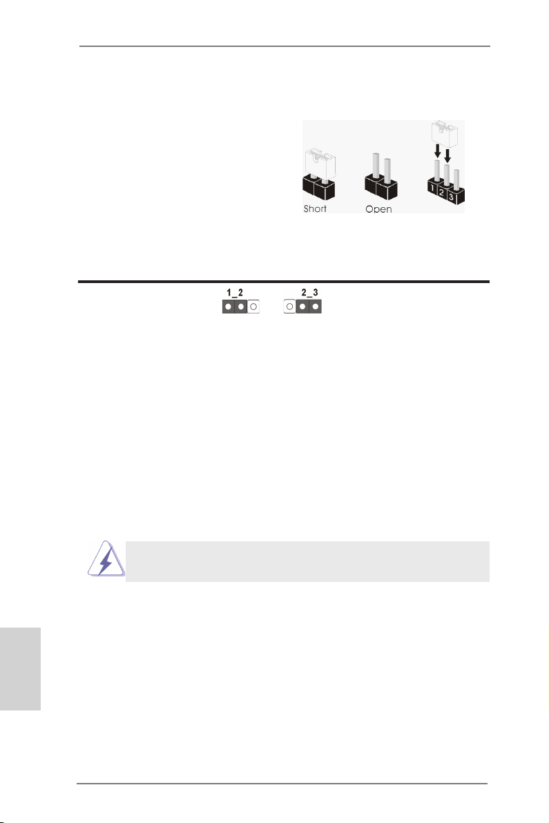
1.3 Einstellung der Jumper
Die Abbildung verdeutlicht, wie Jumper
gesetzt werden. Werden Pins durch
Jumperkappen verdeckt, ist der Jumper
“Gebrückt”. Werden keine Pins durch
Jumperkappen verdeckt, ist der Jumper
“Offen”. Die Abbildung zeigt einen 3-Pin
Jumper dessen Pin1 und Pin2 “Ge-
brückt” sind, bzw. es bendet sich eine
Jumper-Kappe auf diesen beiden Pins.
Jumper Einstellun Beschreibung
CMOS löschen
(CLRCMOS1, 3-Pin jumper)
(siehe S.2, No. 46)
Hinweis:
CLRCMOS1 ermöglicht Ihnen die Löschung der Daten im CMOS. Zum
Löschen und Zurücksetzen der Systemparameter auf die Standardeinrichtung
schalten Sie den Computer bitte aus und trennen das Netzkabel von der
Stromversorgung. Warten Sie 15 Sekunden, schließen Sie dann Pin2 und
Pin3 am CLRCMOS1 über einen Jumper fünf Sekunden lang kurz. Sie
sollten das CMOS allerdings nicht direkt nach der BIOS-Aktualisierung
löschen. Wenn Sie das CMOS nach Abschluss der BIOS-Aktualisierung
löschen müssen, fahren Sie zuerst das System hoch. Fahren Sie es dann
vor der CMOS-Löschung herunter. Bitte beachten Sie, dass Kennwort,
Datum, Uhrzeit, benutzerdeniertes Prol, 1394 GUID und MAC-Adresse
nur gelöscht werden, wenn die CMOS-Batterie entfernt wird.
DefaultEinstellung
CMOS
löschen
Deutsch
64
Der CMOS löschen-Schalter hat dieselbe Funktion wie der CMOS
löschen-Jumper.
ASRock Z77 OC Formula Motherboard
Page 65
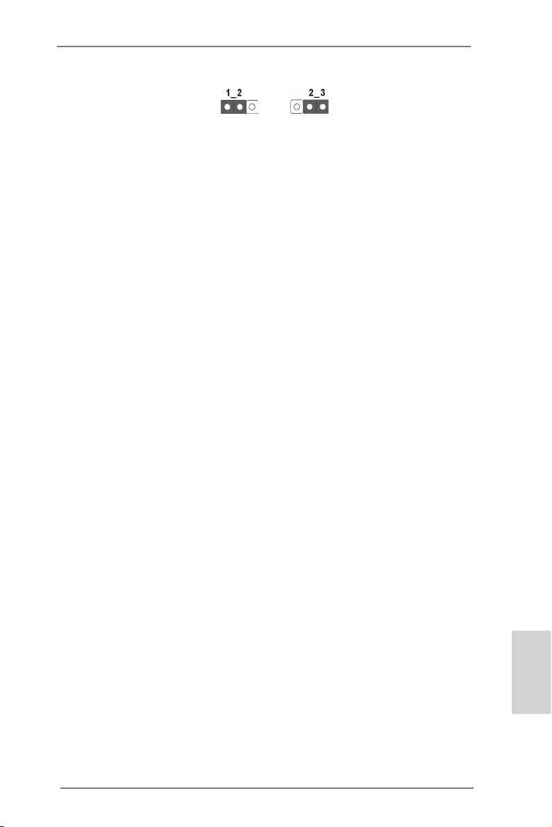
BIOS-Auswahl-Steckbrücke
(BIOS_SEL1)
(siehe S.2, No. 32)
DefaultHaupt-BIOS
SicherungsBIOS
Hinweis:
Das Motherboard ist zur Gewährleistung von Sicherheit und Systemstabilität mit zwei BIOS ausgestattet (Haupt- und Sicherungs-BIOS). Normalerweise arbeitet das System mit dem Haupt-BIOS. Falls das Haupt-BIOS
jedoch beschädigt werden sollte, überbrücken Sie die Pins 2 und 3 mit
einer Steckbrücke – das Sicherungs-BIOS übernimmt nun beim nächsten
Systemstart. Anschließend setzen Sie die Steckbrücke wieder auf die Pins
1 und 2, danach kopieren Sie die BIOS-Datei mit „ASRock Instant Flash“
oder „ASRock Internet Flash“ im BIOS-Setup in das Haupt-BIOS, damit
das System wieder normal gestartet werden kann. Aus Sicherheitsgründen
kann das Sicherungs-BIOS nicht manuell überschrieben werden.
ASRock Z77 OC Formula Motherboard
Deutsch
65
Page 66
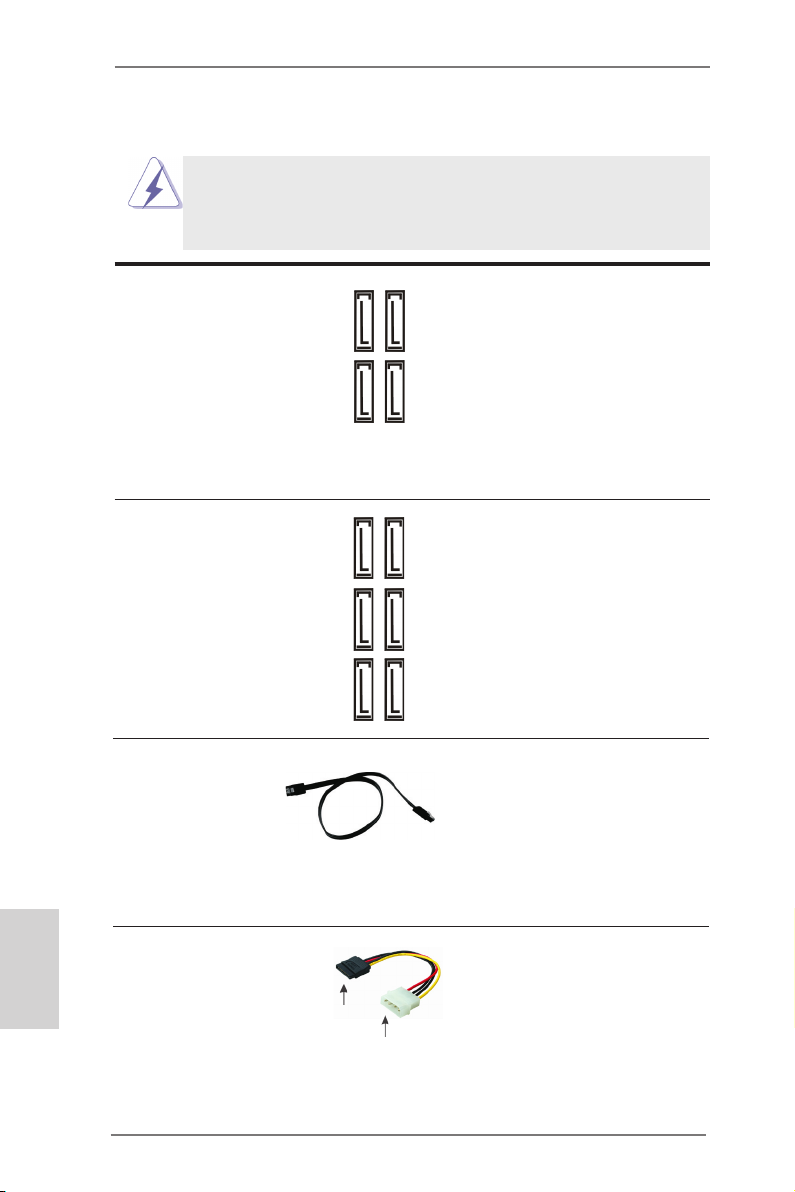
1.4 Integrierte Header und Anschlüsse
Integrierte Header und Anschlüsse sind KEINE Jumper. Setzen Sie KEINE Jumperkappen auf diese Header und Anschlüsse. Wenn Sie Jumperkappen auf Header und Anschlüsse setzen, wird das Motherboard
unreparierbar beschädigt!
Seriell-ATA2-Anschlüsse Diese vier Serial ATA2-
(SATA2_2_3: siehe S.2 - No. 19)
(SATA2_4_5: siehe S.2 - No. 18)
für interne
Massenspeichergeräte. Die
aktuelle SATA2- Schnittstelle
ermöglicht eine
Datenübertragungsrate bis
3,0 Gb/s.
Seriell-ATA3-Anschlüsse Diese sechs Serial ATA3-
(SATA3_0_1: siehe S.2 - No. 20)
(SATA3_M0_M1: siehe S.2 - No. 21)
(SATA3_M2_M3: siehe S.2 - No. 22)
Massenspeichergeräte. Die
aktuelle SATA3- Schnittstelle
ermöglicht eine
Datenübertragungsrate bis 6,0
Gb/s.
(SATA2-)Verbínder
unterstützten SATA-Datenkabel
SATA2_4
SATA2_2
SATA2_5
SATA2_3
(SATA3-)Verbínder
unterstützten SATA-Datenkabel
SATA3_0
SATA3_1
für interne
SATA3_M0
SATA3_M2
SATA3_M1
SATA3_M3
Deutsch
66
Serial ATA- (SATA-) SJedes Ende des SATA
Datenkabel Datenkabels kann an die SATA
(Option)
/ SATA2 / SATA3 Festplatte
oder das SATA2 / SATA3
Verbindungsstück auf dieser
Hauptplatine angeschlossen
werden.
Serial ATA- (SATA-) Verbinden Sie das schwarze
Stromversorgungskabel Ende des SATA-Netzkabels mit
(Option)
dem Netzanschluss am
Laufwerk. Verbinden Sie dann
das weiße Ende des SATA-
SATA-HDD-Stromanschluss
Stromversorgungskabels mit
Verbindung zum
Verbindung zum
Netzteil
dem Stromanschluss des
Netzteils.
ASRock Z77 OC Formula Motherboard
Page 67
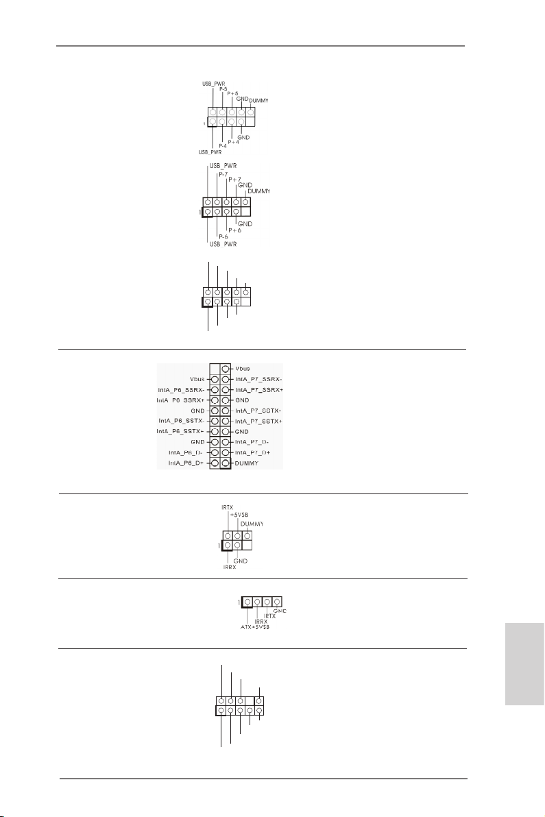
USB 2.0-Header Zusätzlich zu den vier
(9-pol. USB4_5)
(siehe S.2 - No. 31)
üblichen USB 2.0-Ports an den
I/O-Anschlüssen benden sich
drei USB 2.0- Anschlussleisten
am Motherboard. Pro USB 2.0-
(9-pol. USB6_7)
(siehe S.2 - No. 34)
Anschlussleiste werden zwei
USB 2.0-Ports unterstützt.
1
USB _PWR
P-9
P-8
USB _PWR
P+9
P+8
GND
GND
DUM MY
(9-pol. USB8_9)
(siehe S.2 - No. 35)
USB 3.0-Header Neben sechs Standard-USB
(19-pol. USB3_6_7)
(siehe S.2 - No. 15)
3.0-Ports am E/A-Panel
bendet sich ein USB 3.0-
Header an diesem
Motherboard. Dieser USB 3.0 Header kann zwei USB 3.0 Ports unterstützen.
Infrarot-Modul-Header Dieser Header unterstützt ein
(5-pin IR1)
optionales, drahtloses Sende-
(siehe S.2 - No. 38)
und Empfangs-Infrarotmodul.
Consumer Infrared-Modul-Header Dieser Header kann zum
(4-pin CIR1)
(siehe S.2 - No. 36)
Anschließen Remote-
Empfänger.
Anschluss für Audio auf Dieses Interface zu einem
der Gehäusevorderseite Audio-Panel auf der Vorder
(9-Pin HD_AUDIO1)
(siehe S.2 - No. 41)
seite Ihres Gehäuses,
ermöglicht Ihnen eine bequeme
Anschlussmöglichkeit und
Kontrolle über Audio-Geräte.
1
GND
PRE SENC E#
MIC 2_R
MIC 2_L
MIC _RET
J_S ENSE
OUT 2_R
OUT _RET
OUT 2_L
ASRock Z77 OC Formula Motherboard
Deutsch
67
Page 68
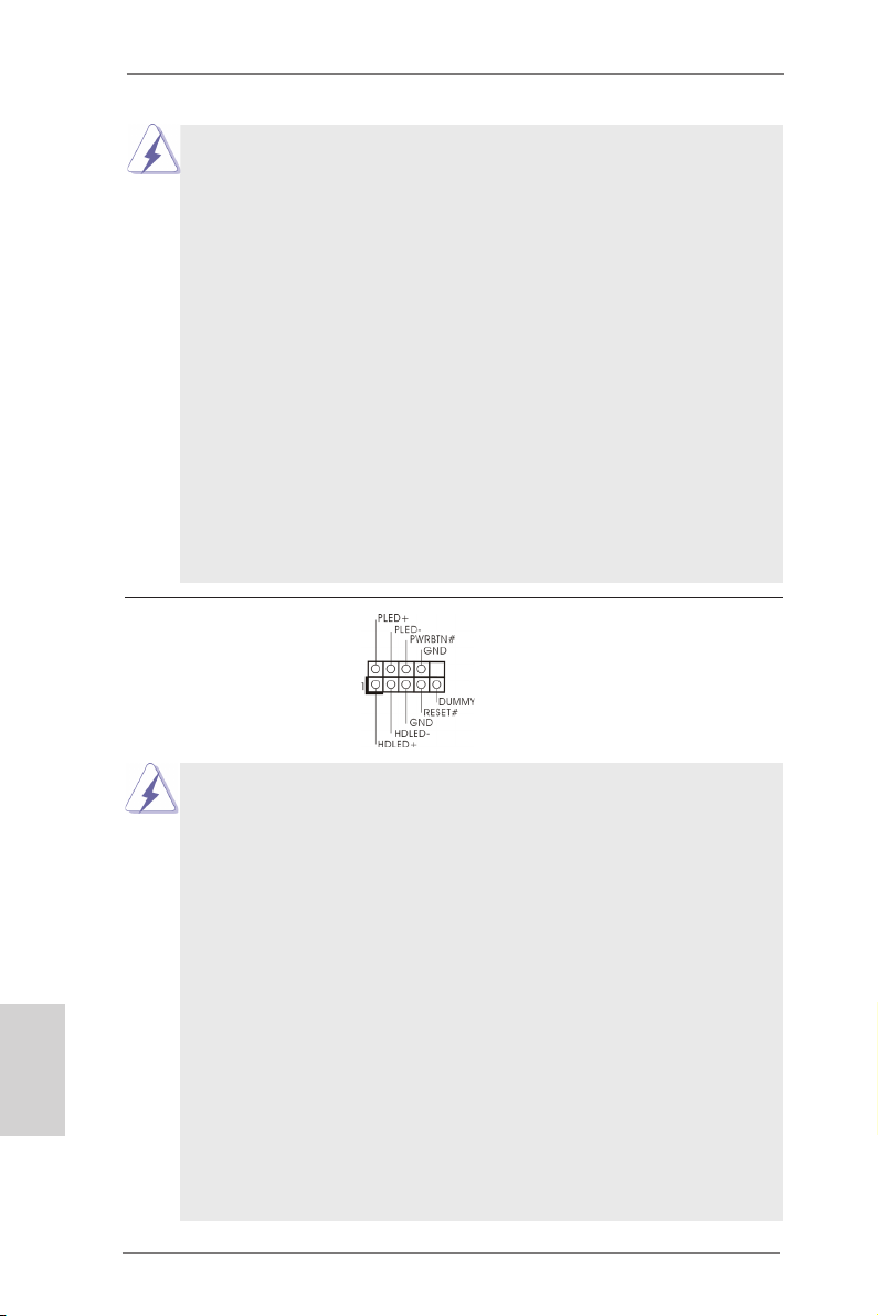
1. High Denition Audio unterstützt Jack Sensing (automatische Erkennung falsch
angeschlossener Geräte), wobei jedoch die Bildschirmverdrahtung am Gehäuse
HDA unterstützen muss, um richtig zu funktionieren. Beachten Sie bei der
Installation im System die Anweisungen in unserem Handbuch und im
Gehäusehandbuch.
2. Wenn Sie die AC’97-Audioleiste verwenden, installieren Sie diese wie
nachstehend beschrieben an der Front-Audioanschlussleiste:
A. Schließen Sie Mic_IN (MIC) an MIC2_L an.
B. Schließen Sie Audio_R (RIN) an OUT2_R und Audio_L (LIN) an OUT2_L an.
C. Schließen Sie Ground (GND) an Ground (GND) an.
D. MIC_RET und OUT_RET sind nur für den HD-Audioanschluss gedacht. Diese
Anschlüsse müssen nicht an die AC’97-Audioleiste angeschlossen werden.
E. So aktivieren Sie das Mikrofon an der Vorderseite.
Bei den Betriebssystemen Windows® XP / XP 64 Bit:
Wählen Sie „Mixer“. Wählen Sie „Recorder“ (Rekorder). Klicken Sie dann auf
„FrontMic“ (Vorderes Mikrofon).
Bei den Betriebssystemen Windows® 7 / 7 64 Bit / VistaTM / VistaTM 64 Bit:
Wählen Sie im Realtek-Bedienfeld die „FrontMic“ (Vorderes Mikrofon) Registerkarte. Passen Sie die „Recording Volume“ (Aufnahmelautstärke) an.
System Panel-Header Dieser Header unterstützt
(9-pin PANEL1)
(siehe S.2 - No. 25)
Schließen Sie die Ein-/Austaste, die Reset-Taste und die
Systemstatusanzeige am Gehäuse an diesen Header an; befolgen Sie
dabei die nachstehenden Hinweise zur Pinbelegung. Beachten Sie die
positiven und negativen Pins, bevor Sie die Kabel anschließen.
mehrere Funktion der
Systemvorderseite.
Deutsch
68
PWRBTN (Ein-/Ausschalter):
Zum Anschließen des Ein-/Ausschalters an der Frontblende des Gehäu
ses. Sie können kongurieren, wie das System mit Hilfe des
Ein-/Ausschalters ausgeschaltet werden können soll.
RESET (Reset-Taste):
Zum Anschließen der Reset-Taste an der Frontblende des Gehäuses.
Mit der Reset-Taste können Sie den Computer im Falle eines Absturzes
neu starten.
PLED (Systembetriebs-LED):
Zum Anschließen der Betriebsstatusanzeige an der Frontblende des
Gehäuses. Die LED leuchtet, wenn das System in Betrieb ist. Die LED
blinkt, wenn sich das System im Ruhezustand S1/S3 bendet. Die LED
schaltet sich aus, wenn sich das System in den Modi S4 bendet
oder ausgeschaltet ist (S5).
ASRock Z77 OC Formula Motherboard
Page 69
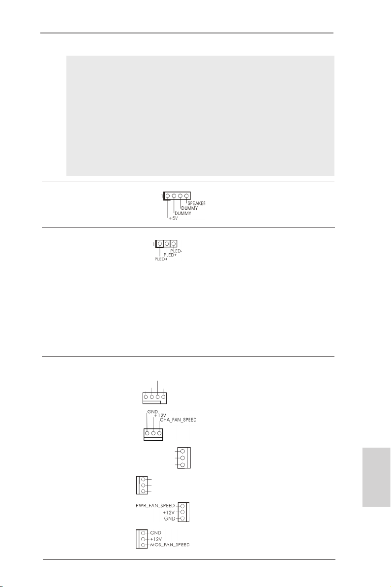
HDLED (Festplattenaktivitäts-LED):
Zum Anschließen der Festplattenaktivitäts-LED an der Frontblende des
Gehäuses. Die LED leuchtet, wenn die Festplatte Daten liest oder
schreibt.
Das Design der Frontblende kann je nach Gehäuse variiere. Ein
Frontblendenmodul besteht hauptsächlich aus einer Ein-/Austaste, einer
Reset-Taste, einer Betriebs-LED, einer Festplattenaktivitäts-LED,
Lautsprechern, etc. Stellen Sie beim Anschließen des
Frontblendenmoduls Ihres Gehäuses an diesem Header sicher, dass die
Kabel- und Pinbelegung korrekt übereinstimmen.
Gehäuselautsprecher-Header Schließen Sie den
(4-pin SPEAKER1)
(siehe S.2 - No. 23)
Gehäuselautsprecher an
diesen Header an.
Betriebs-LED-Header Bitte schließen Sie die
(3-pin PLED1)
(siehe S.2 - No. 24)
Betriebs-LED des Gehäuses
zur Anzeige des
Systembetriebsstatus an
diesem Header an. Die LED
leuchtet, wenn das System in
Betrieb ist. Die LED blinkt im
S1/S3-Zustand. Im S4- oder
S5-Zustand (ausgeschaltet)
leuchtet die LED nicht.
Gehäuse, Strom und MOS lüfteranschlüsse Verbinden Sie die Lüfterkabel
(4-pin CHA_FAN1)
(siehe S.2, No. 37)
mit den Lüfteranschlüssen,
wobei der schwarze Draht an
CHA _FAN _SPE ED
+12 V
FAN _SPE ED_C ONTR OL
GND
den Schutzleiterstift
(3-pin CHA_FAN2)
(siehe S.2 - No. 33)
angeschlossenwird.
(3-pin CHA_FAN3)
(siehe S.2 - No. 17)
(3-pin CHA_FAN4)
(siehe S.2 - No. 49)
(3-pin PWR_FAN1)
(siehe S.2 - No. 16)
(3-pin MOS_FAN1)
(siehe S.2 - No. 50)
CHA _FAN _SP EED
+12 V
GND
GND
+12 V
CHA _FAN_ SPEE D
ASRock Z77 OC Formula Motherboard
Deutsch
69
Page 70
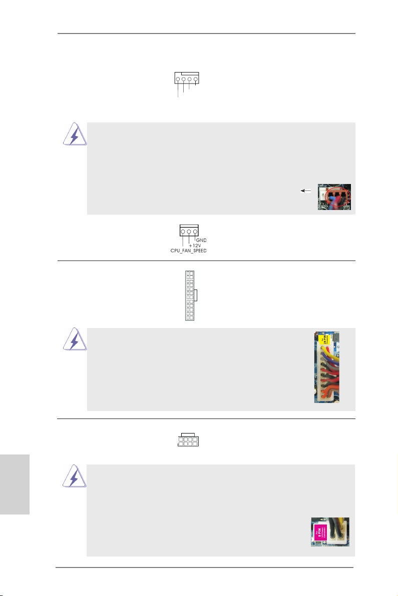
CPU-Lüfteranschluss Verbinden Sie das CPU -
(4-pin CPU_FAN1)
(siehe S.2 - No. 4)
Lüfterkabel mit diesem
Anschluss und passen Sie den
schwarzen Draht dem
4 3 2 1
+12 V
FAN_ SPEE D_CO NTRO L
CPU _FAN_ SPEE D
GND
Erdungsstift an.
Obwohl dieses Motherboard einen vierpoligen CPU-Lüfteranschluss
(Quiet Fan) bietet, können auch CPU-Lüfter mit dreipoligem Anschluss
angeschlossen werden; auch ohne Geschwindigkeitsregulierung. Wenn
Sie einen dreipoligen CPU-Lüfter an den CPU-Lüferanschluss dieses
Motherboards anschließen möchten, verbinden Sie ihn bitte mit den
Pins 1 – 3.
Lüfter mit dreipoligem Anschluss installieren
(3-pin CPU_FAN2)
(sieche S.2 - No. 5)
Pins 1–3 anschließen
Deutsch
ATX-Netz-Header Verbinden Sie die ATX-
(24-pin ATXPWR1)
(siehe S.2 - No. 14)
Obwohl dieses Motherboard einen 24-pol. ATX-
Stromversorgung mit diesem
Header.
12 124
13
12
Stromanschluss bietet, kann es auch mit einem
modizierten traditionellen 20-pol. ATX-Netzteil
verwendet werden. Um ein 20-pol. ATX-Netzteil zu
verwenden, stecken Sie den Stecker mit Pin 1 und
Pin 13 ein.
Installation eines 20-pol. ATX-Netzteils
ATX 12V Anschluss Bitte schließen Sie an diesen
(8-pin ATX12V1)
(siehe S.2 - No. 2)
Anschluss die ATX 12V
Stromversorgung an.
8 5
4 1
1
Obwohl diese Hauptplatine 8-Pin ATX 12V Stromanschluss zur Verfügung
stellt, kann sie noch arbeiten, wenn Sie einen traditionellen 4-Pin ATX 12V
Energieversorgung adoptieren. Um die 4-Pin ATX Energieversorgung zu
verwenden, stecken Sie bitte Ihre Energieversorgung zusammen mit dem
Pin 1 und Pin 5 ein.
Installation der 4-Pin ATX 12V Energieversorgung
8 5
4 1
24
24
13
13
70
ASRock Z77 OC Formula Motherboard
Page 71
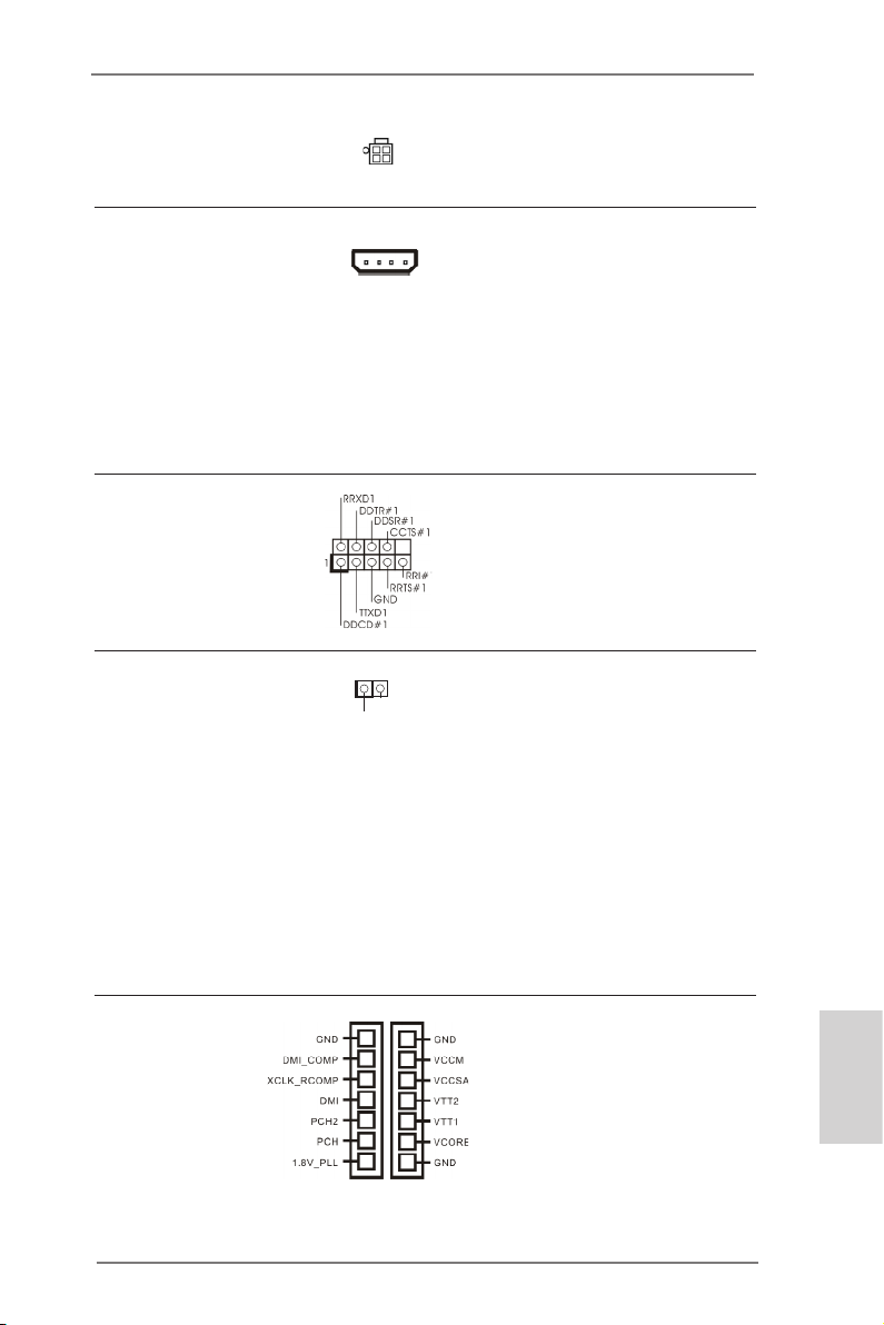
(4-pin ATX12V2)
(siehe S.2 - No. 1)
SLI/XFIRE-Stromanschluss Sie müssen diesen Anschluss
(4-pin SLI/XFIRE_PWR1)
(siehe S.2 - No. 39)
Grakkarten gleichzeitig am
nicht zwingend verwenden.
Wenn allerdings zwei
SLI/XFIRE_POWER1
Motherboard angeschlossen
sind, verbinden Sie diesen
Anschluss bitte mit einem
Festplatten-Stromversorgungs stecker.
COM-Anschluss-Header Dieser COM-Anschluss- Header
(9-pin COM1)
(siehe S.2 - No. 40)
wird verwendet, um ein
COM-Anschlussmodul zu
unterstützen.
HDMI_SPDIF-Anschluss Der HDMI_SPDIF-Anschluss
(2-pin HDMI_SPDIF1)
(siehe S.2 - No. 42)
stellt einen SPDIF-
Audioausgang für eine HDMI-
1
SPD I FOUT
GND
VGA-Karte zur Verfügung und
ermöglicht den Anschluss von
HDMI-Digitalgeräten wie
Fernsehgeräten, Projektoren,
LCD-Geräten an das System.
Bitte verbinden Sie den
HDMI_SPDIF-Anschluss der
HDMI-VGA-Karte mit diesem
Anschluss.
V-ProbeTM Benutzer können die
(7-pin VOL_CON1,
7-pin VOL_CON2)
(siehe S.2 - No. 13)
Spannung von Onboard-
Komponenten messen,
inklusive VCCM, VCCSA,
VTT2, VTT1, VCORE,
DMI_COMP, XCLK_RCOMP,
DMI, PCH2, PCH und
1.8V_PLL
ASRock Z77 OC Formula Motherboard
Deutsch
71
Page 72
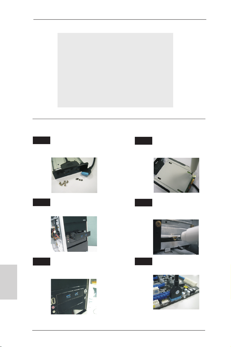
VCCM: DRAM-Spannung
VCCSA: CPU-Systemagentspannung
VTT2: VTT-Hauptspannung
VTT1: Sekundäre VTT-Spannung
VCORE: CPU-Core-Spannung
DMI_COMP: DMI COMP-Spannung
XCLK_RCOMP: COMP-Spannung, interner Taktgenerator
DMI: DMI-Spannung
PCH2: Chipsatz-Core-Spannung
PCH: Sekundäre Chipsatz-Core-Spannung
1.8V_PLL: CPU PLL-Spannung
Installationsanleitung der USB 3.0-Frontblende
Schritt 1
Halten Sie die mitgelieferte USB 3.0Frontblende, vier Festplattenschrauben
und sechs Gehäuseschrauben bereit.
Schritt 2
Montieren Sie die 2,5 Zoll-HDD/SSD
mit vier Festplattenschrauben an der
USB 3.0-Frontblende.
Deutsch
72
Schritt 3
Installieren Sie die USB 3.0-Frontblende im
2,5 Zoll-Festplatteneinschub des Gehäuses.
Schritt 5
Schließen Sie das Kabel der
USB 3.0-Frontblende am USB 3.0-Header
(USB3_6_7) am Motherboard an.
ASRock Z77 OC Formula Motherboard
Montieren Sie die USB 3.0-Frontblende
Schritt 4
mit sechs Gehäuseschrauben am
Festplatteneinschub.
Schritt 6
Die USB 3.0-Frontblende ist nun
einsatzbereit.
Page 73
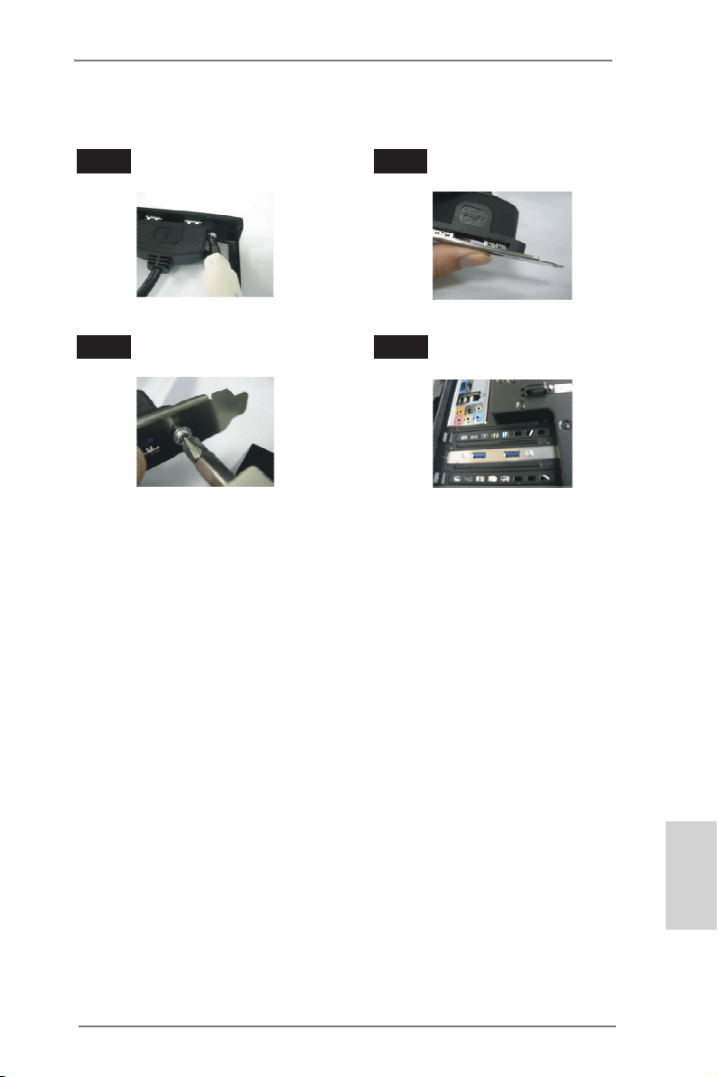
Installationsanleitung zum USB 3.0-Blech an der Rückwand
Schritt 1 Schritt 2
Schritt 3 Schritt 4
Lösen Sie die beiden Schrauben am
USB 3.0-Panel.
Fixieren Sie das USB 3.0-Blech mit
Schrauben an der Rückwand.
Schließen Sie das USB 3.0-Kabel an
das USB 3.0-Blech an.
Setzen Sie das USB 3.0-Blech an
der Rückwand des Gehäuses ein.
ASRock Z77 OC Formula Motherboard
Deutsch
73
Page 74

1.5 Schnellschalter
Das Motherboard verfügt über sechs spezielle Taster: Ein-/Austaste, Reset-Taste
und CMOS-löschen-Taste – zum schnellen Aus- und Einschalten des Systems und
zum Löschen der CMOS-Werte; Plus/Minus-Tasten (Rapid OC) – zum schnellen
und einfachen Anpassen der Übertaktungsfrequenz; PCIe ein/aus – drei Tasten zum
Aktivieren oder Deaktivieren der PCIE-Steckplätze mit einem einzigen Tastendruck.
Netzschalter Der Netzschalter ist ein
(PWRBTN)
(siehe S.2 - No. 27)
ein-/ausschalten können.
Rücksetzschalter (Reset) Der Rücksetzschalter (Reset)
(RSTBTN)
(siehe S.2 - No. 28)
zurücksetzen können.
CMOS löschen-Schalter Der CMOS löschen-Schalter ist
(CLRCBTN)
(siehe S.3 - No. 14)
schnell löschen können.
Rapid OC-Tasten (+/-) Mit den Rapid OC-Tasten (+/-)
(MINUS1: siehe S.2 - No. 10)
(PLUS1: siehe S.2 - No. 11)
schnell und einfach per Rapid
OC an.
Schnellschalter, mit dem
Pow er
Benutzer das System schnell
ist ein Schnellschalter, mit dem
Benutzer das System schnell
Res et
ein Schnellschalter, mit dem
Benutzer die CMOS-Werte
passen Sie
Übertaktungsfrequenzen
Deutsch
74
Das Overclocking-Verhalten ist abhängig von der Konguration des Systems,
wie z. B. Speicher-Fähigkeit, thermische Lösung, usw. Overclocking beeinus
sen Ihr System Stabilität oder sogar zu Schäden an den Komponenten und
Geräte. Wir sind nicht Verantwortung für mögliche Schäden durch Übertaktung
verursacht worden.
ASRock Z77 OC Formula Motherboard
Page 75

PCIe-Ein-/Ausschalter Mit dem PCIe-Ein-/Ausschalter
(SWITCH1)
(siehe S.2 - No. 9)
aktivieren oder deaktivieren Sie
die entsprechenden PCIE x16-
Steckplätze. Falls eine
1: PCIE2
2: PCIE4
3: PCIE5
installierte PCIE x16-Karte nicht
funktionieren sollte, können Sie
die fehlerhafte Karte per
PCIe-Ein-/Ausschalter mit
einem Tastendruck ermitteln,
ohne die Karten ausbauen zu
müssen.
1. Achten Sie darauf, dass das System komplett abgeschaltet ist, bevor Sie
Tasten oder Schalter betätigen.
2. Beim Abschalten per PCIe-Ein-/Ausschalter kann die PCIE-Karte zerstört
werden, falls diese nachlässig entwickelt wurde. Weitere Informationen zu
technischen Daten und Eigenschaften der Karte erhalten Sie vom
Kartenhersteller.
3. Der PCIe-Ein-/Ausschalter dient ausschließlich zur Fehlersuche. Falls Sie
eine PCIE-Karte nicht nutzen möchten, trennen Sie diese bitte vollständig
vom Motherboard.
ASRock Z77 OC Formula Motherboard
Deutsch
75
Page 76

2. BIOS-Information
Das Flash Memory dieses Motherboards speichert das Setup-Utility. Drücken Sie
<F2> oder <Del> während des POST (Power-On-Self-Test) um ins Setup zu gelangen, ansonsten werden die Testroutinen weiter abgearbeitet. Wenn Sie ins Setup
gelangen wollen, nachdem der POST durchgeführt wurde, müssen Sie das System
über die Tastenkombination <Ctrl> + <Alt> + <Delete> oder den Reset-Knopf auf
der Gehäusevorderseite, neu starten. Natürlich können Sie einen Neustart auch
durchführen, indem Sie das System kurz ab- und danach wieder anschalten.
Das Setup-Programm ist für eine bequeme Bedienung entwickelt worden. Es ist
ein menügesteuertes Programm, in dem Sie durch unterschiedliche Untermenüs
scrollen und die vorab festgelegten Optionen auswählen können. Für detaillierte
Informationen zum BIOS-Setup, siehe bitte das Benutzerhandbuch (PDF Datei) auf
der Support CD.
3. Software Support CD information
Dieses Motherboard unterstützt eine Reiche von Microsoft® Windows® Betriebssystemen: 7 / 7 64-Bit / VistaTM / Vista
beigefügte Support-CD enthält hilfreiche Software, Treiber und Hilfsprogramme, mit
denen Sie die Funktionen Ihres Motherboards verbessern können Legen Sie die
Support-CD zunächst in Ihr CD-ROM-Laufwerk ein. Der Willkommensbildschirm
mit den Installationsmenüs der CD wird automatisch aufgerufen, wenn Sie die
“Autorun”-Funktion Ihres Systems aktiviert haben.
Erscheint der Wilkommensbildschirm nicht, so “doppelklicken” Sie bitte auf das File
ASSETUP.EXE im BIN-Verzeichnis der Support-CD, um die Menüs aufzurufen.
Das Setup-Programm soll es Ihnen so leicht wie möglich machen. Es ist menügesteuert, d.h. Sie können in den verschiedenen Untermenüs Ihre Auswahl treffen und
die Programme werden dann automatisch installiert.
TM
64-Bit / XP / XP 64-Bit. Die Ihrem Motherboard
Deutsch
76
ASRock Z77 OC Formula Motherboard
Page 77

1. Introduction
Merci pour votre achat d’une carte mère ASRock Z77 OC Formula, une carte mère
très able produite selon les critères de qualité rigoureux de ASRock. Elle offre des
performances excellentes et une conception robuste conformément à l’engagement
d’ASRock sur la qualité et la abilité au long terme. Ce Guide d’installation rapide
présente la carte mère et constitue un guide d’installation pas à pas. Des informations plus détaillées concernant la carte mère pourront être trouvées dans le manuel
l’utilisateur qui se trouve sur le CD d’assistance.
Les spécications de la carte mère et le BIOS ayant pu être mis à jour, le
contenu de ce manuel est sujet à des changements sans notication. Au
cas où n’importe qu’elle modication intervenait sur ce manuel, la version
mise à jour serait disponible sur le site web ASRock sans nouvel avis.
Vous trouverez les listes de prise en charge des cartes VGA et CPU
également sur le site Web ASRock.
Site web ASRock, http://www.asrock.com
Si vous avez besoin de support technique en relation avec cette carte
mère, veuillez consulter notre site Web pour de plus amples informations
particulières au modèle que vous utilisez.
www.asrock.com/support/index.asp
1.1 Contenu du paquet
Carte mère ASRock Z77 OC Formula
(Facteur de forme CEB: 12.0 pouces x 10.5 pouces, 30.5 cm x 26.7 cm)
Guide d’installation rapide ASRock Z77 OC Formula
CD de soutien ASRock Z77 OC Formula
Six câbles de données de série ATA (SATA) (en option)
Deux câble d’alimentation de série ATA (SATA) HDD (en option)
Un I/O Panel Shield
Un panneau avant USB 3.0
Quatre HDD vis
Six châssis vis
Un support arrière USB 3.0
Un carte 2S_Pont_ASRock SLI
Dix Supports OC
Pâte thermique GELID GC-Extreme
ASRock vous rappelle...
Pour bénécier des meilleures performances sous Windows® 7 / 7 64 bits
TM
/ Vista
/ VistaTM 64 bits, il est recommandé de paramétrer l'option BIOS
dans Conguration de stockage en mode AHCI. Pour plus de détails sur
l'installation BIOS, référez-vous au "Mode d'emploi" sur votre CD de sup-
port.
ASRock Z77 OC Formula Motherboard
Français
77
Page 78

Français
1.2 Spécifications
Format - Facteur de forme CEB:
12.0 pouces x 10.5 pouces, 30.5 cm x 26.7 cm
- Design de condensateur Premium Gold (condensateurs
polymère conducteur de qualité supérieure 100% fabriqués
au Japon)
Kit OC Formula Kit OC Formula Power
- Conception Digi Power
- MOSFET double-pile (Dual-Stack MOSFET, DSM)
(voir ATTENTION 1)
- Filtre Multiple (Multiple Filter Cap , MFC) (ltre différents
bruits à l’aide de 3 différents condensateurs : Filtre solide
DIP, POSCAP et MLCC)
- Bobine en alliage de première qualité (réduit de 70% les
pertes dans le noyau par comparaison avec les bobines en
alliage de poudre de fer)
Kit connecteur OC Formula
- Connecteur poudre haute-densité
- 15μ Gold Finger (supports mémoire et CPU)
Kit de refroidissement OC Formula
- Refroidissement double puissance (combinant
refroidissement actif par air et refroidissement par eau)
- PCB 8 couches
- 4 x 56,7g de cuivre
- Pâte thermique GELID GC-Extreme
CPU - Prend en charge les processeurs Intel® CoreTM i7 / i5 / i3
2ème et 3ème génération sur socket LGA1155
- 12 + 4 Power Phase conception
- Prend en charge la technologie Intel® Turbo Boost 2.0
- Prise en charge des unités centrales non verrouillées de
série K
- Prise en charge de la technologie Hyper-Threading
(voir ATTENTION 2)
Chipsets - Intel® Z77
- Prend en charge les technologies Intel® Rapid Start et Smart
Connect
Mémoire - Compatible avec la Technologie de Mémoire à Canal
Double (voir ATTENTION 3)
- 4 x slots DIMM DDR3
- Supporter DDR3 3000+(OC)/2800(OC)/2666(OC)/2400(OC)
/2133(OC)/1866(OC)/1600/1333/1066 non-ECC, sans
78
ASRock Z77 OC Formula Motherboard
Page 79

amortissement mémoire
- Capacité maxi de mémoire système: 32GB
(voir ATTENTION 4)
- Prend en charge le prol de mémoire extrême Intel® (XMP)
1.3/1.2
Slot d’extension - 2 x slots PCI Express 3.0 x16 (PCIE2/PCIE4 : simple à x16
(PCIE2) / x8 (PCIE4) ou double en mode x8/x8)
(voir ATTENTION 5)
* PCIE 3.0 n’est pris en charge qu’avec le processeur Intel®
Ivy Bridge. Avec le processeur Intel® Sandy Bridge, seul
PCIE 2.0 est pris en charge.
- 1 x slot PCI Express 2.0 x16 (PCIE5 : mode x4)
- 2 x slot PCI Express 2.0 x1
- Prend en charge AMD Quad CrossFireXTM, 3-Way
CrossFireXTM et CrossFireX
- Prend en charge NVIDIA® Quad SLITM et SLI
TM
TM
VGA sur carte * Intel® HD Graphics avec visuels intégrés (Built-in Visuals) et
les sorties VGA sont uniquement pris en charge par les
processeurs à GPU intégré.
- Supporte Intel® HD Graphics Built-in Visuals: Intel® Quick
Sync Video 2.0, Intel® InTruTM 3D, Intel® Clear Video HD
Technology, Intel® InsiderTM, Intel® HD Graphics 2500/4000
- Pixel Shader 5.0, DirectX 11 avec CPU Intel® Ivy Bridge,
Pixel Shader 4.1, DirectX 10.1 avec CPU Intel® Sandy
Bridge
- Mémoire partagée max 1760MB (voir ATTENTION 6)
- Prend en charge le HDMI 1.4a avec une résolution
maximale jusqu’à 1920x1200 @ 60Hz
- Prend en charge Lip Sync, Deep Color (12bpc), xvYCC et
HBR (High Bit Rate Audio : Audio à haut débit binaire) avec
HDMI (Moniteur compatible HDMI requis)
(voir ATTENTION 7)
- Prise en charge de la fonction HDCP avec port HDMI
- Supporter 1080p Blu-ray(BD)/ lecteur de HD-DVD avec
port HDMI
Audio - 7,1 CH HD Audio avec protection de contenu
(Realtek ALC898 Audio Codec)
- Prise en charge de l’audio Premium Blu-ray
LAN - PCIE x1 Gigabit LAN 10/100/1000 Mb/s
- Broadcom BCM57781
- Support du Wake-On-LAN
Français
ASRock Z77 OC Formula Motherboard
79
Page 80

Français
- Prend en charge la norme Energy Efcient Ethernet
(Ethernet à efcacité énergétique) 802.3az
- Supporte PXE
Panneau arrière I/O Panel
- 1 x port clavier/souris PS/2
- 1 x port HDMI
- 1 x Port de sortie optique SPDIF
- 4 x ports USB 2.0 par défaut
- 6 x ports USB 3.0 par défaut
- 1 x port LAN RJ-45 avec LED (ACT/LED CLIGNOTANTE
et LED VITESSE)
- 1 x interrupteur d’effacement du CMOS avec LED
- Prise HD Audio: Haut-parleur arrière / Central /Basses /
Entrée Ligne / Haut-parleur frontal / Microphone
(voir ATTENTION 8)
SATA3 - 2 x connecteurs SATA3 6,0 Gb/s par Intel® Z77, prennent en
charge les fonctions RAID (RAID 0, RAID 1, RAID 5,
RAID 10, Intel Rapid Storage et Intel Smart Response),
NCQ, AHCI et « Hot Plug » (Branche ment à chaud)
- 4 x connecteurs SATA3 6,0 Gb/s par Marvell SE9172,
prennent en charge les fonctions RAID (RAID 0 et RAID 1),
NCQ, AHCI et « Hot Plug » (Branche ment à chaud)
USB 3.0 - 2 x ports USB3.0 à l’arrière par Intel® Z77, prennent en
charge USB 1.0/2.0/3.0 jusqu’à 5 Gb/s
- 4 x ports USB3.0 à l’arrière par Etron EJ188H, prennent en
charge USB 1.0/2.0/3.0 jusqu’à 5 Gb/s
- 1 x barrette USB3.0 en façade (prend en charge 2 ports
USB 3.0) par Intel® Z77, prend en charge USB 1.0/2.0/3.0
jusqu’à 5 Gb/s
Connecteurs - 4 x connecteurs SATA2, prennent en charge un taux de
transfert de données pouvant aller jusqu’à 3.0Go/s,
supporte RAID (RAID 0, RAID 1, RAID 5, RAID 10, Intel
Rapid Storage et Intel Smart Response), NCQ, AHCI et
Hot Plug (Branchement à chaud)
- 6 x connecteurs SATA3, prennent en charge un taux de
transfert de données pouvant aller jusqu’à 6.0Go/s
- 1 x En-tête du module infrarouge
- 1 x Barrette pour module à infrarouges grand public
- 1 x En-tête de port COM
- 1 x Connecteur HDMI_SPDIF
- 1 x Connecteur de LED d’alimentation
- V-ProbeTM: 2 x 7 paires de points de mesure de la tension
80
ASRock Z77 OC Formula Motherboard
Page 81

sur carte intégrés
- 2 x Connecteur pour ventilateur de CPU (1 x br. 4, 1 x br. 3)
- 4 x Connecteur pour ventilateur de Châssis
(1 x br. 4, 3 x br. 3)
- 1 x Connecteur pour ventilateur de pouvoir (br. 3)
- 1 x Connecteur pour ventilateur de MOS (br. 3)
- br. 24 connecteur d’alimentation ATX
- br. 8 connecteur d’alimentation 12V ATX
- br. 4 connecteur d’alimentation 12V ATX
- Connecteur d’alimentation SLI/XFIRE
- Connecteur audio panneau avant
- 3 x En-tête USB 2.0 (prendre en charge 6 ports USB 2.0
supplémentaires)
- 1 x En-tête USB 3.0 (prendre en charge 2 ports USB 3.0
supplémentaires)
- 1 x Dr. Debug (LED de débogage à 7 segments)
- 1 x interrupteur d’alimentation avec LED
- 1 x interrupteur de réinitialisation avec LED
- 1 x interrupteur d’effacement du CMOS avec LED
- Bouton OC rapide : boutons +/- pour ajuster la fréquence
OC
- 1 x interrupteur ON/OFF PCIe
- Véricateur d’état des postes (PSC) (voir ATTENTION 9)
BIOS - 2 x 64Mb AMI UEFI Legal BIOS avec support GUI (1 x BIOS
principal et 1 x BIOS de sauvegarde pour récupération)
- Support du “Plug and Play”
- Compatible pour événements de réveil ACPI 1.1
- Support SMBIOS 2.3.1
- CPU Core, IGPU, DRAM, 1.8V PLL, VTT, VCCSA Tension
Multi-ajustement
CD d’assistance - Pilotes, utilitaires, logiciel anti-virus (version d’évaluation),
CyberLink MediaEspresso 6.5 Trial, Suite multimédia
ASRock MAGIX - OEM
Caractéristique - Formula Drive (voir ATTENTION 10)
unique - ASRock l’Instant Boot
- ASRock Instant Flash (voir ATTENTION 11)
- Chargeur ASRock APP (voir ATTENTION 12)
- ASRock SmartView (voir ATTENTION 13)
- ASRock XFast USB (voir ATTENTION 14)
- ASRock XFast LAN (voir ATTENTION 15)
- ASRock XFast RAM (voir ATTENTION 16)
- ASRock Crashless BIOS (voir ATTENTION 17)
ASRock Z77 OC Formula Motherboard
Français
81
Page 82

Français
- ASRock OMG (Online Management Guard)
(voir ATTENTION 18)
- ASRock Internet Flash (voir ATTENTION 19)
- ASRock UEFI System Browser
- Fonction déshumidicateur ASRock (voir ATTENTION 20)
- ASRock Interactive UEFI
- Prole OC de NickShih (voir ATTENTION 21)
- Contrôleur-V à réglage n (voir ATTENTION 22)
- Timing Congurator
- Lucid Virtu Universal MVP (voir ATTENTION 23)
* Lucid Virtu Universal MVP est uniquement pris en charge
par les processeurs à GPU intégré.
- L’accélérateur hybride:
- ASRock U-COP (voir ATTENTION 24)
- Garde d’échec au démarrage (B.F.G.)
- DEL veilleuse
Surveillance - Détection de la température de processeur/châssis/pouvoir/
système MOS
- Tachéomètre ventilateur processeur/châssis/pouvoir/MOS
ventilateur
- Ventilateur silencieux pour unité centrale/châssis/MOS
(permet le réglage automatique de la vitesse du ventilateur
pour châssis, selon la température de l’unité centrale)
- Commande de ventilateur CPU/Châssis/MOS à plusieurs
vitesses
- Moniteur thermique à points multiples
- Monitoring de la tension: +12V, +5V, +3.3V, Vcore
OS - Microsoft® Windows® 7 / 7 64-bit / VistaTM / Vista
TM
64-bit
/ XP / XP 64-bit (voir ATTENTION 25)
Certications - FCC, CE, WHQL
- Prêt pour ErP/EuP (alimentation Prêt pour ErP/EuP requise)
(voir ATTENTION 26)
* Pour de plus amples informations sur les produits, s’il vous plaît visitez notre site web:
http://www.asrock.com
82
ASRock Z77 OC Formula Motherboard
Page 83

ATTENTION
Il est important que vous réalisiez qu’il y a un certain risque à effectuer
l’overclocking, y compris ajuster les réglages du BIOS, appliquer la technologie
Untied Overclocking, ou utiliser des outils de tiers pour l’overclocking. L’overclocking
peut affecter la stabilité de votre système, ou même causer des dommages aux
composants et dispositifs de votre système. Si vous le faites, c’est à vos frais et
vos propres risques. Nous ne sommes pas responsables des dommages possibles
causés par l’overclocking.
ATTENTION!
1. Le MOSFET double-stack (DSM) est un concept novateur des transis-
tors à effet de champ à grille isolée, ou MOSFET. La zone de la puce
siliconée est en effet doublée par l’entassement de deux puces dans un
MOSFET. Plus cette zone est large, plus faible sera le Rds(on). Comparé
aux traditionnels et discrets MOSFET, le DSM offre ainsi une zone de
microplaquette plus élargie et un Rds(on) moins élevé, de telle sorte que
l’alimentation du processeur Vcore soit encore plus performante.
2. En ce qui concerne le paramétrage “Hyper-Threading Technology”,
veuillez consulter la page 69 du manuel de l’utilisateur sur le CD technique.
3. Cette carte mère supporte la Technologie de Mémoire à Canal Double.
Avant d’intégrer la Technologie de Mémoire à Canal Double, assurezvous de bien lire le guide d’installation des modules mémoire en page 18
pour réaliser une installation correcte.
4. Du fait des limites du système d’exploitation, la taille mémoire réelle
réservée au système pourra être inférieure à 4 Go sous Windows® 7 /
VistaTM / XP. Avec Windows® OS avec CPU 64 bits, il n’y a pas ce genre
de limitation. Vous pouvez utiliser ASRock XFast RAM pour accéder à la
mémoire que Windows® ne peut pas utiliser.
5. PCIE2 et PCIE4 prend en charge une vitesse pouvant atteindre Gen 3.
Pour pouvoir utiliser PCI Express en vitesse Gen 3, vous devez installer
le processeur Ivy Bridge. Si vous installez le processeur Sandy Bridge,
PCI Express ne fonctionnera qu’en vitesse PCI Express Gen 2.
6. La dimension maximum du memoire partage est denie par le vendeur
de jeu de puces et est sujet de changer. Veuillez verier la Intel® website
pour les informations recentes SVP.
7. xvYCC et Deep Color ne sont pris en charge que sous Windows® 7 64-
bit / 7. Le mode Deep Color ne sera activé que si le moniteur prend en
charge 12bpc en EDID. HBR est pris en charge sous Windows® 7 64-bit /
7 / VistaTM 64-bit / VistaTM.
8. Pour l’entrée microphone, cette carte mère supporte les deux modes
stéréo et mono. Pour la sortie audio, cette carte mère supporte les
modes 2-canaux, 4-canaux, 6-canaux et 8-canaux. Veuillez vous référer
au tableau en page 3 pour effectuer la bonne connexion.
Français
ASRock Z77 OC Formula Motherboard
83
Page 84

Français
9. Le Véricateur d’état des postes (PSC) permet de diagnostiquer l’état de
l’ordinateur au moment de sa mise en route par l’utilisateur. Il émet une
lumière rouge pour indiquer que le processeur, la mémoire, le VGA ou
le stockage est défaillant. Si ces quatre composants sont en bon état de
fonctionnement, la lumière s’éteint.
10. Formula Drive est un utilitaire tout-en-un qui permet de régler
précisément différentes fonctions du système, via une interface facile
à utiliser, incluant Moniteur de périphériques, Fan-tastic Tuning,
Overclocking, OC DNA et IES. Dans Moniteur de périphériques, il afche
les valeurs principales de votre système. Dans Fan-tastic Tuning, il
afche la vitesse du ventilateur et la température, que vous pouvez
ajuster. Dans Overclocking, vous pouvez overclocker la fréquence du
CPU pour améliorer les performances du système. Dans OC DNA, vous
pouvez enregistrer vos réglages OC dans un prol et les partager avec
vos amis. Vos amis pourront alors installer le prol OC sur leur système
pour utiliser les mêmes réglages OC. Dans IES (Intelligent Energy
Saver – Fonction intelligente d’économie d’énergie), le contrôleur de la
tension peut réduire le nombre de phases de sortie pour améliorer le
fonctionnement lorsque les cores du CPU ne sont pas utilisées, sans
diminuer les performances de l’ordinateur. Veuillez visiter notre site
Web pour plus d’informations sur l’utilisation des fonctions de l’utilitaire
Formula Drive. Site Web de ASRock : http://www.asrock.com
11. O ASRock Instant Flash é um utilitário de ash do BIOS incorporado
na memória Flash ROM. Esta prática ferramenta de actualização do
BIOS permite-lhe actualizar o BIOS do sistema sem necessitar de entrar
nos sistemas operativos, como o MS-DOS ou o Windows®. Com este
utilitário, poderá premir a tecla <F6> durante o teste de arranque POST
ou premir a tecla <F2> para exibir o menu de conguração do BIOS para
aceder ao ASRock Instant Flash. Execute esta ferramenta para guardar
o novo cheiro de BIOS numa unidade ash USB, numa disquete ou
num disco rígido, em seguida, poderá actualizar o BIOS com apenas
alguns cliques sem ter de utilizar outra disquete ou outro complicado
utilitário de ash. Note que a unidade ash USB ou a unidade de disco
rígido devem utilizar o sistema de cheiros FAT32/16/12.
12. Si vous désirez un moyen plus rapide et moins contraignant de recharger
vos appareils Apple tels que iPhone/iPad/iPod Touch, ASRock a préparé
pour vous la solution idéale - le chargeur ASRock APP. Il suft d’installer
le pilote du chargeur APP, et vous pourrez recharger rapidement votre
iPhone à partir de votre ordinateur, jusqu’à 40% plus vite qu’avant. Le
chargeur ASRock APP vous permet de charger rapidement et simultanément plusieurs appareils Apple, et le chargement continu est même pris
en charge lorsque le PC passe en mode Veille (S1), Suspension à
la RAM (S3), hibernation (S4) ou hors tension (S5). Lorsque le pilote du
chargeur APP est installé, vous découvrez un mode de mise en charge
tout à fait inédit.
Site web ASRock : http://www.asrock.com/Feature/AppCharger/index.asp
84
ASRock Z77 OC Formula Motherboard
Page 85

13. SmartView, une nouvelle fonction du navigateur Internet, est une page
de démarrage intelligente de IE, comportant à la fois vos sites Internet
les plus visités, votre historique, vos amis Facebook et l’actualité en
temps réel, le tout sur une vue optimisée pour une expérience de l’Internet
encore plus personnelle. Les cartes mères ASRock sont équipées en
exclusivité de l’utilitaire SmartView, ce qui vous permet de garder le
contact avec vos amis itinérants. Pour utiliser la fonction SmartView,
veuillez vous assurez que votre version de système d’exploitation est
Windows® 7 / 7 64 bits / VistaTM / VistaTM 64 bits, et que vous utilisez le
navigateur IE8. Site Internet ASRock : http://www.asrock.com/Feature/
SmartView/index.asp
14. ASRock XFast USB permet d’améliorer les performances de votre périphérique de stockage USB. Les performances réelles dépendent des
propriétés du périphérique.
15. ASRock XFast LAN fournit un accès Internet plus rapide, avec les avantages suivants. Priorisation d’application LAN : Vous pouvez congurer
votre priorité d’application idéalement et/ou ajouter des nouveaux programmes. Latence plus basse dans les jeux : Après avoir réglé la priorité
de jeux en ligne plus haute, cela peut réduire la latence dans les jeux.
Forme du trac : Vous pouvez regarder des vidéos HD YouTube et télécharger simultanément des chiers. Analyse en temps réel de vos données : Avec la fenêtre d’état, vous pouvez facilement reconnaître les ux
de données que vous êtes en train de transférer.
16. ASRock XFast RAM est une nouvelle fonction intégrée à l’utilitaire
Formula Drive. Il utilise à sa pleine capacité l’espace mémoire que les
processeurs du système d’exploitation Windows OS 32-bit ne peuvent
pas utiliser. ASRock XFast RAM diminue le temps de chargement des
sites Internet précédemment visités, rendant la navigation sur le web plus
rapide que jamais. Il rend également l’utilisation de Adobe Photoshop 5
fois plus rapide. Un autre avantage indéniable de ASRock XFast RAM
est qu’il réduit la fréquence d’accès à vos SSD ou HDD an d’accroitre
leur durée de vie utile.
17. ASRock Crashless BIOS permet aux utilisateurs de mettre à jour leur
BIOS sans qu’ils aient à craindre un plantage ou une défaillance. Si
l’alimentation venait à être coupée durant la mise à jour du BIOS, ASRock Crashless BIOS terminera automatiquement la mise à jour du BIOS
une fois le courant rétabli. Veuillez noter que les chiers BIOS doivent
être placés dans le répertoire racine de votre disque USB. Seuls les
ports USB2.0 sont compatibles avec cette fonction.
18. Via OMG, les administrateurs ont la possibilité d’instaurer un couvrefeu Internet ou de spécier des plages horaires durant lesquelles l’accès
Internet sera restreint. Il est ainsi possible de congurer l’heure de début
et l’heure de n autorisant l’accès à Internet par les autres utilisateurs.
An d’éviter que ces derniers ne puissent contourner le système OMG,
il est nécessaire de créer des comptes invité non dotés d’un accès aux
réglages de l’heure du système.
Français
ASRock Z77 OC Formula Motherboard
85
Page 86

Français
19. La fonction Internet Flash recherche les mises à jour disponibles pour le
microprogramme UEFI sur nos serveurs. En d’autres termes, le système
est capable de détecter automatiquement la mise à jour UEFI la plus
récente sur nos serveurs et la transmet sans avoir à accéder au système
d’exploitation Windows. Veuillez noter que le service DHCP doit être activé sur votre ordinateur pour pouvoir utiliser cette fonction.
20. L’utilisateur peut prévenir les dégâts sur la carte mère dus à l’humidité en
activant la “ Fonction déshumidicateur “. Lors de l’activation de la fonction déshumidicateur, l’ordinateur se met en marche automatiquement
pour déshumidier le système après être entré à l’état S4/S5.
21. Le Prole OC de NickShih est une option de BIOS qui afche la façon
dont Nick, le champion global OC overclocke cette carte mère. Il offre un
moyen pratique et efcace d’utiliser les réglages OC de Nick simpliant
le processus complexe de l’overclockage.
22. En plus des options de conguration conventionnelle de tension dans
l’utilitaire d’installation UEFI, le Contrôleur-V à réglage n est une nouvelle collection d’options de réglages ns de tension pour overclockage
extrême.
23. VIRTU Universal MVP intègre toutes les fonctionnalités de base de la
technologie Virtu Universal, qui virtualise GPU intégrée et GPU discrète
pour des fonctionnalités optimales. Il est également doté de la fonction
Virtual VsyncTM pour une qualité visuelle sans compromis. Ajoutez à cela
les avantages de la technologie HyperFormance, et VIRTU Universal
MVP vous permettra d’obtenir des performances de jeu inégalées en
réduisant intelligemment les tâches redondantes du rendu lors du ux
entre le CPU, le GPU de la carte graphique et l’écran.
24. Lorsqu’une surchauffe du CPU est détectée, le système s’arrête automa-
tiquement. Avant de redémarrer le système, veuillez vérier que le ventilateur d’UC sur la carte mère fonctionne correctement et débranchez le
cordon d’alimentation, puis rebranchez-le. Pour améliorer la dissipation
de la chaleur, n’oubliez pas de mettre de la pâte thermique entre le CPU
le dissipateur lors de l’installation du PC.
25. ASRock XFast RAM n’est pas pris en charge par Microsoft® Windows®
XP / XP 64-bit. Les technologie Intel® Smart Connect et ports Intel® USB
3.0 n’est pas pris en charge par Microsoft® Windows® VistaTM / VistaTM 64-
bit / XP / XP 64-bit.
26. EuP, qui signie Energy Using Product (Produit Utilisant de l’Energie), est
une disposition établie par l’Union Européenne pour dénir la consom-
mation de courant pour le système entier. Conformément à la norme
EuP, le courant CA total du système entier doit être inférieur à 1 W en
mode d’arrêt. Pour être conforme à la norme EuP, une carte mère EuP et
une alimentation EuP sont requises. Selon les suggestions d’Intel’,
86
ASRock Z77 OC Formula Motherboard
Page 87
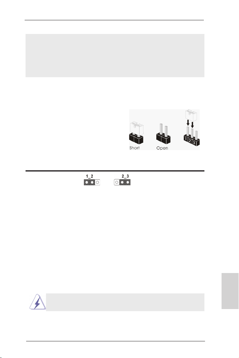
l’alimentation électrique EuP doit correspondre à la norme, qui est que
l’efcacité électrique de 5v en mode de veille doit être supérieure à 50%
pour 100 mA de consommation de courant. Pour choisir une alimentation
électrique conforme à la norme EuP, nous vous recommandons de consulter votre fournisseur de courant pour plus de détails.
1.3 Réglage des cavaliers
L’illustration explique le réglage des cavaliers. Quand un capuchon est placé sur les
broches, le cavalier est « FERME ». Si aucun capuchon ne relie les broches,le cavalier est « OUVERT ». L’illustration montre un
cavalier à 3 broches dont les broches 1 et 2
sont « FERMEES » quand le capuchon est
placé sur ces 2 broches.
Le cavalier Description
Effacer la CMOS
(CLRCMOS1)
(voir p.2 g. 46)
Remarque :
Paramètres
par défaut
CLRCMOS1 vous permet d’effacer les données du CMOS. Pour effacer
et réinitialiser les paramètres du système à la conguration originale,
veuillez éteindre l’ordinateur et débrancher le cordon d’alimentation de
la prise de courant. Après 15 secondes, utilisez un couvercle de jumper
pour court-circuiter les broches pin2 et pin3 de CLRCMOS1 pendant
secondes. Veuillez cependant ne pas effacer le CMOS immédiatement
a
près avoir mis à jour le BIOS. Si vous avez besoin d’effacer le CMOS
après avoir mis à jour le BIOS, vous devez allumer en premier le
système, puis l’éteindre avant de continuer avec l’opération d’effacement
du CMOS. Veuillez noter que le mot de passe, la date, l’heure, le prol
par défaut de l’utilisateur, 1394 GUID et l’adresse MAC seront effacés
seulement si la batterie du CMOS est enlevée.
Effacer la
CMOS
5
Le commutateur Effacer CMOS présente la même fonction que le
cavalier Effacer CMOS.
ASRock Z77 OC Formula Motherboard
Français
87
Page 88
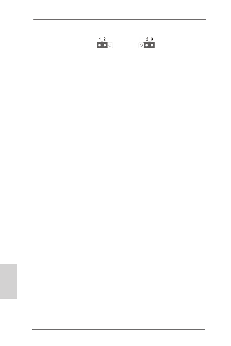
Jumper de sélection BIOS
(BIOS_SEL1)
(voir p.2 g. 32)
Par défaut
(BIOS principal)
Sauvegarde
BIOS
Remarque :
Cette carte mère dispose de deux BIOS, un BIOS principal et un BIOS
de sauvegarde, pour une meilleure protection de sûreté et de stabilité
de votre système. Normalement le système fonctionne sur le BIOS
principal. Cependant si le BIOS principal est corrompu ou endommagé,
utilisez un jumper pour neutraliser les pin2 et pin3, le BIOS de sauveg-
arde sera utilisé au prochain redémarrage système. Ensuite, neutralisez
les pin1 et pin2 à nouveau, puis utilisez “ASRock Instant Flash“ ou “AS-
Rock Internet Flash“ dans l’utilitaire d’installation du BIOS pour copier
le chier BIOS sur le BIOS principal an d’assurer un fonctionnement
normal du système. Pour la sécurité du système, les utilisateurs ne
peuvent pas mettre à jour manuellement le BIOS de sauvegarde.
Français
88
ASRock Z77 OC Formula Motherboard
Page 89
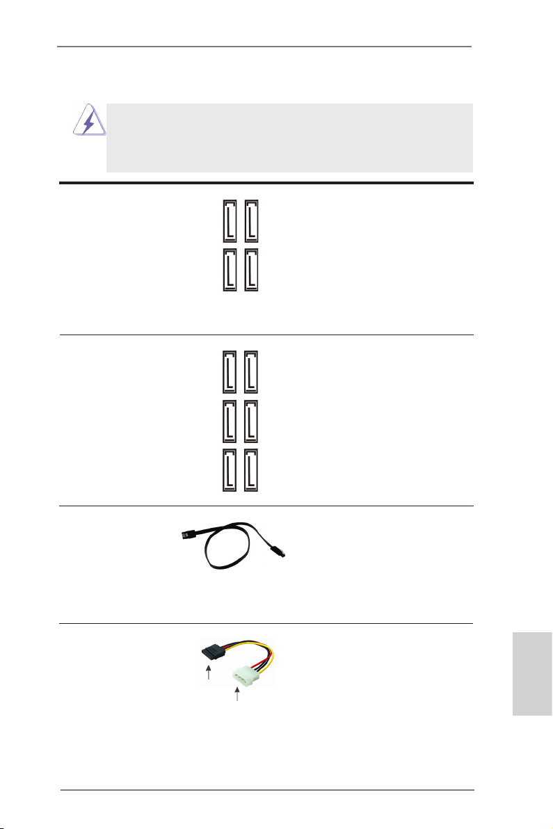
1.4 En-têtes et Connecteurs sur Carte
Les en-têtes et connecteurs sur carte NE SONT PAS des cavaliers.
NE PAS placer les capuchons de cavalier sur ces en-têtes et connecteurs. Le fait de placer les capuchons de cavalier sur les en-têtes
et connecteurs causera à la carte mère des dommages irréversibles!
Connecteurs Série ATA2 Ces quatre connecteurs Série
(SATA2_2_3: voir p.2 No. 19)
(SATA2_4_5: voir p.2 No. 18)
les périphériques de stockage
internes. L’interface SATA2
actuelle permet des taux
transferts de données pouvant
aller jusqu’à 3,0 Gb/s.
Connecteurs Série ATA3 Ces six connecteurs Série
(SATA3_0_1: voir p.2 No. 20)
(SATA3_M0_M1: voir p.2 No. 21)
(SATA3_M2_M3: voir p.2 No. 22)
internes. L’interface SATA3
actuelle permet des taux
transferts de données pouvant
aller jusqu’à 6,0 Gb/s.
ATA2 (SATA2) prennent en
charge les câbles SATA pour
SATA2_4
SATA2_2
SATA2_5
SATA2_3
ATA3 (SATA3) prennent en
charge les câbles SATA pour
SATA3_0
les périphériques de stockage
SATA3_M0
SATA3_1
SATA3_M1
SATA3_M2
SATA3_M3
Câble de données Tout e cot e du cable de data
Série ATA (SATA) SATA peut etre connecte au
(en option)
disque dur SATA / SATA2 /
SATA3 ou au connecteur SATA2
/ SATA3 sur la carte
mere.
Cordon d’alimentation Veuillez connecter l’extrémité
Série ATA (SATA) noire du cordon d’alimentation
(en option)
SATA sur le connecteur
d’alimentation sur chaque unité.
Connectez ensuite l’extrémité
blanche du cordon
d’alimentation SATA sur le
connecteur d’alimentation de
connecter au connecteur
d’alimentation du disque
dur SATA
c o n n e c t e r à
l’unité
d’alimentation
électrique
l’unité d’alimentation électrique.
ASRock Z77 OC Formula Motherboard
Français
89
Page 90

En-tête USB 2.0 A côté des quatre ports USB 2.0
(USB4_5 br. 9)
(voir p.2 No. 31)
par défaut sur le panneau E/S,
il y a trois embases USB 2.0
sur cette carte mère. Chaque
embase USB 2.0 peut prendre
(USB6_7 br. 9)
(voir p.2 No. 34)
en charge 2 ports USB 2.0.
Français
1
USB _PWR
P-9
P-8
USB _PWR
P+9
P+8
GND
GND
DUM MY
(USB8_9 br. 9)
(voir p.2 No. 35)
En-tête USB 3.0 En plus des six ports USB
(USB3_6_7 br. 19)
(voir p.2 No. 15)
3.0 par défaut sur le panneau
E/S, il y a une barrette USB 3.0
sur la carte mère. Cette barrette
USB 3.0 peut prendre en
charge deux ports USB 3.0.
En-tête du module infrarouge Cet en-tête supporte un module
(IR1 br. 5)
infrarouge optionnel de transfert
(voir p.2 No. 38)
et de réception sans l.
Barrette pour module à infrarouges grand public Cette barrette peut être utilisée
(CIR1 br.4)
(voir p.2 No. 36)
pour connecter des récepteur
Connecteur audio panneau C’est une interface pour un
(HD_AUDIO1 br. 9)
(voir p.2 No. 41)
câble avant audio en façade qui
permet le branchement et le
contrôle commodes de
périphériques audio.
1
1
GND
GND
PRE SENC E#
PRE SENC E#
MIC 2_R
MIC 2_R
MIC 2_L
MIC 2_L
MIC _RET
MIC _RET
J_S ENSE
J_S ENSE
OUT 2_R
OUT 2_R
OUT _RET
OUT _RET
OUT 2_L
OUT 2_L
90
ASRock Z77 OC Formula Motherboard
Page 91
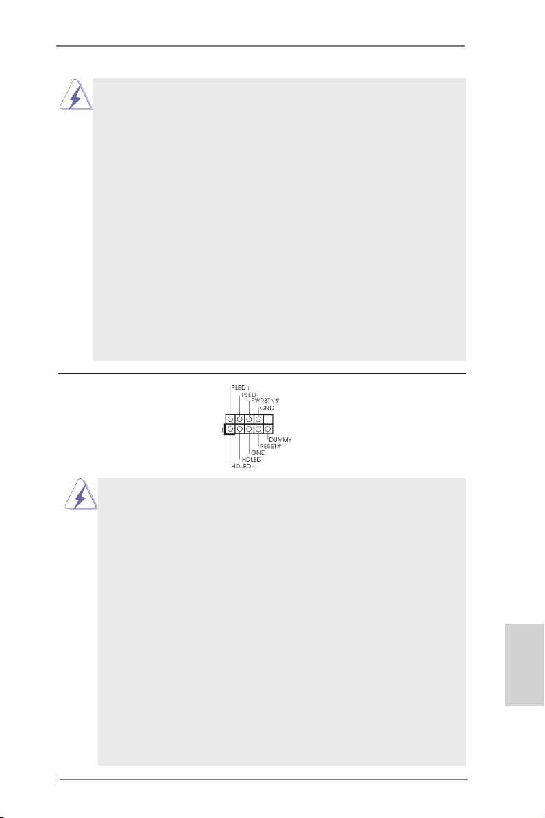
1. L’audio à haute dénition (HDA) prend en charge la détection de che, mais le l
de panneau sur le châssis doit prendre en charge le HDA pour fonctionner
correctement. Veuillez suivre les instructions dans notre manuel et le manuel de
châssis an installer votre système.
2. Si vous utilisez le panneau audio AC’97, installez-le sur l’adaptateur audio
du panneau avant conformément à la procédure ci-dessous:
A. Connectez Mic_IN (MIC) à MIC2_L.
B. Connectez Audio_R (RIN) à OUT2_R et Audio_L (LIN) à OUT2_L.
C. Connectez Ground (GND) à Ground (GND).
D. MIC_RET et OUT_RET sont réservés au panneau audio HD. Vous
n’avez pas besoin de les connecter pour le panneau audio AC’97.
E. Pour activer le micro avant.
Pour les systèmes d’exploitation Windows® XP / XP 64 bits :
Sélectionnez “Mixer”. Sélectionnez “Recorder” (Enregistreur). Puis
cliquez sur “FrontMic” (Micro avant).
Pour les systèmes d’exploitation Windows® 7 / 7 64 bits / VistaTM /
VistaTM 64 bits :
Allez sur l’onglet “FrontMic” (Micro avant) sur le Panneau de contrôle
Realtek. Ajustez “Recording Volume” (Volume d’enregistrement).
En-tête du panneau système Cet en-tête permet d’utiliser
(PANEL1 br. 9)
(voir p.2 No. 25)
plusieurs fonctions du panneau
système frontal.
Connectez l’interrupteur d’alimentation, l’interrupteur de réinitialisation et
l’indicateur d’état du système du châssis sur cette barrette en respectant
l’affectation des broches décrite ci-dessous. Faites attention aux broches
positives et négatives avant de connecter les câbles.
PWRBTN (Interrupteur d’alimentation):
Connectez ici le connecteur d’alimentation sur le panneau avant du
châssis. Vous pouvez congurer la façon de mettre votre système hors
tension avec l’interrupteur d’alimentation.
RESET (Interrupteur de réinitialisation):
Connectez ici le connecteur de réinitialisation sur le panneau avant du
châssis. Appuyez sur l’interrupteur de réinitialisation pour redémarrer
l’ordinateur s’il se bloque ou s’il n’arrive pas à redémarrer normalement.
PLED (DEL alimentation système):
Connectez ici l’indicateur d’état de l’alimentation sur le panneau avant du
châssis. Ce voyant DEL est allumé lorsque le système est en marche.
Le voyant DEL clignote lorsque le système est en mode veille S1/S3. Le
voyant DEL est éteint lorsque le système est en mode veille S4 ou
lorsqu’il est éteint (S5).
ASRock Z77 OC Formula Motherboard
Français
91
Page 92

HDLED (DEL activité du disque dur):
Connectez ici le voyant DEL d’activité du disque dur sur le panneau
avant du châssis. Ce voyant DEL est allumé lorsque le disque dur est en
train de lire ou d’écrire des données.
Le design du panneau avant peut varier en fonction du châssis. Un
module de panneau avant consiste principalement en : interrupteur
d’alimentation, interrupteur de réinitialisation, voyant DEL d’alimentation,
voyant DEL d’activité du disque dur, haut-parleur, etc. Lorsque vous
connectez le panneau avant de votre châssis sur cette barrette, vériez
bien à faire correspondre les ls et les broches.
En-tête du haut-parleur Veuillez connecter le
de châssis haut-parleur de châssis sur cet
(SPEAKER1 br. 4)
(voir p.2 No. 23)
en-tête.
LED di accensione Collegare il LED di accensione
(PLED1 br. 3)
(voir p.2 Nr. 24)
chassi per indicare lo stato di
alimentazione del sistema. Il
LED è acceso quando il sistema
è in funzione. Il LED continua a
lampeggiare in stato S1/S3. Il
LED è spento in stato S4 o S5
(spegnimento).
Français
Connecteur pour CPU, châssis et Branchez les câbles du
pouvoir ventilateur ventilateur aux connecteurs
(CHA_FAN1 br. 4)
(voir p.2 No. 37)
pour ventilateur et faites
correspondre le l noir à la
CHA _FAN _SPE ED
+12 V
FAN _SPE ED_C ONTR OL
GND
broche de terre.
(CHA_FAN2 br. 3)
(voir p.2 No. 33)
(CHA_FAN3 br. 3)
(voir p.2 No. 17)
(CHA_FAN4 br. 3)
(voir p.2 No. 49)
(PWR_FAN1 br. 3)
(voir p.2 No. 16)
(MOS_FAN1 br. 3)
(voir p.2 No. 50)
CHA _FAN _SP EED
+12 V
GND
GND
+12 V
CHA _FAN_ SPEE D
92
ASRock Z77 OC Formula Motherboard
Page 93

Connecteur du ventilateur Veuillez connecter le câble de
4 3 2 1
de l’UC ventilateur d’UC sur ce
(CPU_FAN1 br. 4)
(voir p.2 No. 4)
connecteur et brancher le l
noir sur la broche de terre.
FAN_ SPEE D_CO NTRO L
Bien que cette carte mère offre un support de (Ventilateur silencieux
ventilateur de CPU à 4 broches , le ventilateur de CPU à 3 broches peut
bien fonctionner même sans la fonction de commande de vitesse du
ventilateur. Si vous prévoyez de connecter le ventilateur de CPU à 3
broches au connecteur du ventilateur de CPU sur cette carte mère,
veuillez le connecter aux broches 1-3.
Installation de ventilateur à 3 broches
(CPU_FAN2 br. 3)
(voir p.2 No. 5)
GND
+12 V
CPU _FAN_ SPEE D
Broches 1-3 connectées
En-tête d’alimentation ATX Veuillez connecter l’unité
(ATXPWR1 br. 24)
(voir p.2 No. 14)
Bien que cette carte mère fournisse un connecteur de
d’alimentation ATX sur cet en-
tête.
12 124
13
12
24
courant ATX 24 broches, elle peut encore fonctionner
si vous adopter une alimentation traditionnelle ATX 20
broches. Pour utiliser une alimentation ATX 20 broches,
branchez à l’alimentation électrique ainsi qu’aux
broches 1 et 13.
20-Installation de l’alimentation électrique ATX
Connecteur ATX 12V Veuillez connecter une unité
(ATX12V1 br.8)
(voir p.2 No. 2)
d’alimentation électrique ATX
12V sur ce connecteur.
8 5
4 1
1
13
Bien que cette carte mère possède 8 broches connecteur d’alimentation
ATX 12V, il peut toujours travailler si vous adoptez une approche
traditionnelle à 4 broches ATX 12V alimentation.
8 5
Pour utiliser l’alimentation des 4 broches ATX,
branchez votre alimentation avec la broche 1 et
la broche 5.
4-Installation d’alimentation à 4 broches ATX 12V
4 1
Français
ASRock Z77 OC Formula Motherboard
93
Page 94

(ATX12V2 br.4)
(voir p.2 No. 1)
Connecteur d’alimentation SLI/XFIRE Il n’est pas nécessaire d’utiliser
(SLI/XFIRE_POWER1 br. 4)
(voir p.2 No. 39)
d’alimentation pour disques
ce connecteur, mais veuillez le
brancher avec un connecteur
SLI/XFIRE_POWER1
durs quand deux cartes
graphiques sont branchées sur
cette carte mère en même
temps.
En-tête de port COM Cette en-tête de port COM est
(COM1 br.9)
(voir p.2 No. 40)
utilisée pour prendre en charge
un module de port COM.
Français
Connecteur HDMI_SPDIF Connecteur HDMI_SPDIF,
(HDMI_SPDIF1 2-pin)
(voir p.2 No. 42)
SPDIF vers la carte VGA HDMI,
fournissant une sortie audio
1
GND
SPD I FOUT
et permettant au système de se
connecter au un téléviseur
numérique HDMI /un projecteur
/ un périphérique LCD. Veuillez
brancher le connecteur
HDMI_SPDIF de la carte VGA
HDMI sur ce connecteur.
V-ProbeTM Les utilisateurs ont la possibilité
(VOL_CON1 7-pin,
VOL_CON2 7-pin)
(voir p.2 No. 13)
de mesurer la tension des
composants sur carte, dont
VCCM, VCCSA, VTT2, VTT1,
VCORE, DMI_COMP,
XCLK_RCOMP, DMI, PCH2,
PCH et 1.8V_PLL.
94
ASRock Z77 OC Formula Motherboard
Page 95

VCCM : tension DRAM
VCCSA : Tension du system agent du CPU
VTT2 : tension du VTT principal
VTT1 : tension du second VTT
VCORE : tension du cœur du CPU
DMI_COMP : DMI COMP
XCLK_RCOMP : tension d’horloge interne gen COMP
DMI : tension DMI
PCH2 : tension du cœur du Chipset
PCH : tension du cœur du second chipset
1.8V_PLL : tension de CPU PLL
Le Guide d’installation du panneau USB 3.0 frontal
Etape 1
Préparez le panneau USB 3.0 frontal fourni,
quatre vis HDD et six vis de châssis.
Etape 3
Installez le panneau USB 3.0 frontal dans la
baie de disque 2,5” du châssis.
Etape 5
Branchez le câble USB 3.0 dans le
connecteur USB 3.0 (USB3_6_7) de la carte
mère.
Vissez le HDD/SSD 2,5” sur le
Etape 2
panneau USB 3.0. frontal avec
les quatre vis HDD.
Vissez le panneau USB 3.0 frontal
Etape 4
dans la baie de disque avec les six
vis de châssis.
Etape 6
Le panneau USB 3.0 frontal peut
maintenant être utilisé.
Français
ASRock Z77 OC Formula Motherboard
95
Page 96
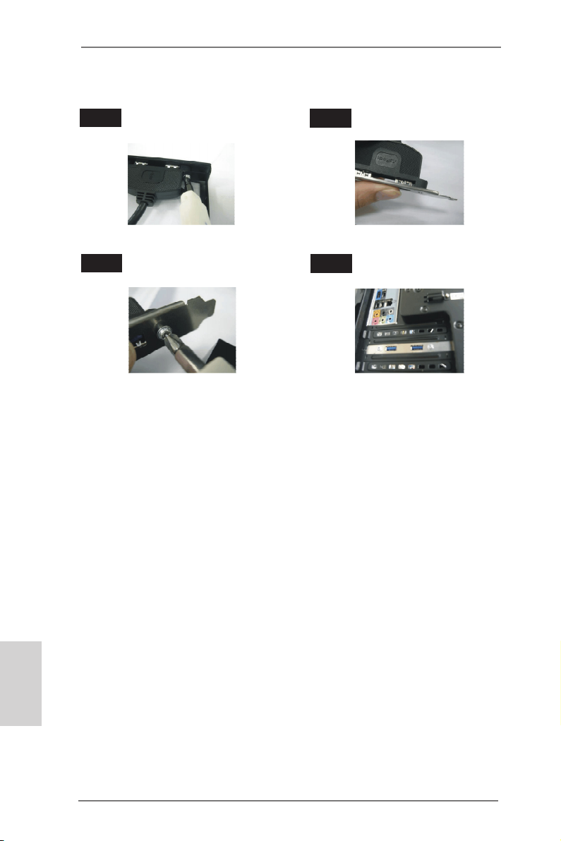
Le Guide d'installation du Support arrière USB 3.0
Étape 1
Étape 3
Dévissez les deux vis du panneau
avant USB 3.0.
Vissez les deux vis dans le support
arrière USB 3.0.
Étape 2
Assemblez le câble USB 3.0 et le
support arrière USB 3.0.
Étape 4
Placez le support arrière USB 3.0
dans le châssis.
Français
96
ASRock Z77 OC Formula Motherboard
Page 97
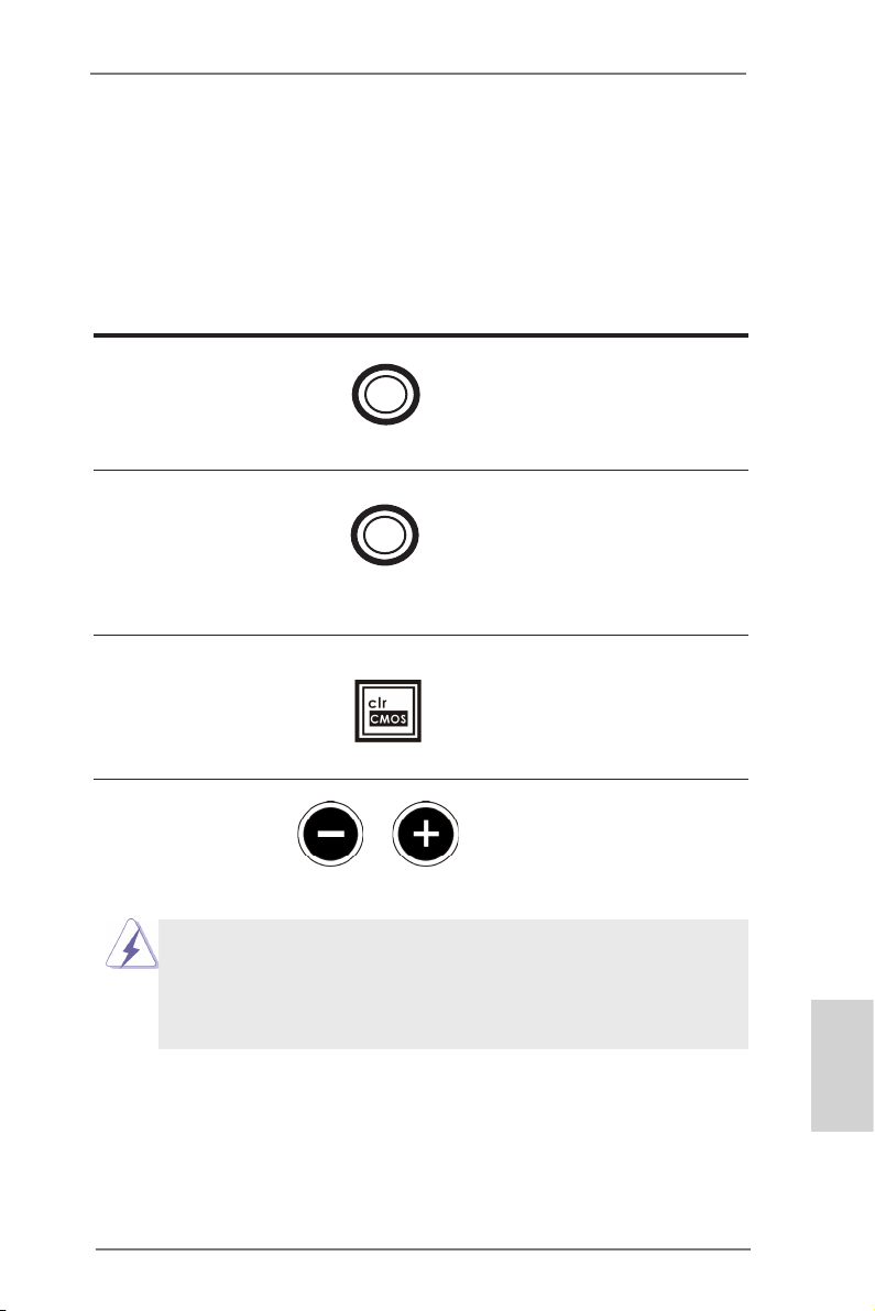
1.5 Interrupteur rapides
La carte mère dispose de six interrupteurs intelligents : alimentation, réinitialisation,
mise en marche et effacement CMOS, permettant aux utilisateurs d’allumer/éteindre
rapidement ou de réinitialiser les valeurs CMOS du système ; boutons OC de + / rapide, permettant aux utilisateurs de régler rapidement et facilement la fréquence
OC ; mettre en marche/arrêt PCIe, offrant aux utilisateurs trois interrupteurs pour
activer ou désactiver les slots PCIE d’un simple clic.
Interrupteur d’alimentation
(PWRBTN)
(voir p.2 No. 27)
Interrupteur de réinitialisation
(RSTBTN)
(voir p.2 No. 28)
Interrupteur d’effacement de CMOS
(CLRCBTN)
(voir p.3 No. 14)
Boutons OC de + / - rapide
(MINUS1: voir p.2 No. 10)
(PLUS1: voir p.2 No. 11)
Ce comportement overclocking dépend de la conguration du système, tels
que capacité de la mémoire, solution thermique, etc Overclocking peuvent af
fecter votre système la stabilité, ou même causer des dommages aux
composants et périphériques. Nous ne sommes pas responsable d’éventuels
dommages causés par l’overclocking.
Pow er
Res et
L’interrupteur d’alimentation est
un interrupteur rapide, qui permet
à l’utilisateur d’allumer/éteindre
rapidement le système.
L’interrupteur de réinitialisation
est un interrupteur rapide, qui
permet à l’utilisateur de
réinitialiser rapidement le
système.
L’interrupteur d’effacement de
CMOS est un interrupteur rapide
qui permet à l’utilisateur d’effacer
rapidement les valeurs du CMOS.
Les boutons OC de + / - rapide
permettent à l’utilisateur d’ajuster
rapidement et facilement la fré-
quence OC dans le OC de rapide.
ASRock Z77 OC Formula Motherboard
Français
97
Page 98
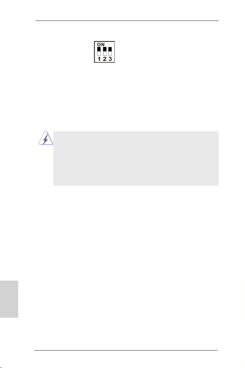
Interrupteur de mise en L’interrupteur de mise en
marche/arrêt PCIe marche/arrêt PCIe vous permet
(SWITCH1)
(voir p.2 No. 9)
d’activer ou désactiver les 16
slots PCIE correspondants.
1: PCIE2
2: PCIE4
3: PCIE5
Lorsque l’une des cartes PCIE
x16 installée est en
dérangement, vous pouvez
utiliser l’interrupteur de mise
en marche/arrêt PCIe an de
détecter celle qui est hors
service et d’un simple clic retirer
les cartes.
1. Assurez-vous de mettre le système hors tension avant de changer les
interrupteurs.
2. Lorsque vous éteignez l’interrupteur PCIe, votre carte PCIE risque de griller
si elle est de mauvaise qualité. Pour plus d’informations sur les
spécications de votre carte, contacter le vendeur.
3. Interrupteur de mise en marche/arrêt PCIe est destiné uniquement au
débuggage. Si vous ne voulez pas utiliser votre carte PCIE, retirez-la de la
carte mère.
Français
98
ASRock Z77 OC Formula Motherboard
Page 99

2. Informations sur le BIOS
La puce Flash Memory sur la carte mère stocke le Setup du BIOS. Lorsque vous
démarrez l’ordinateur, veuillez presser <F2> ou <Del> pendant le POST (Power-OnSelf-Test) pour entrer dans le BIOS; sinon, le POST continue ses tests de routine. Si
vous désirez entrer dans le BIOS après le POST, veuillez redémarrer le système en
pressant <Ctl> + <Alt> + <Suppr>, ou en pressant le bouton de reset sur le boîtier
du système. Vous pouvez également redémarrer en éteignant le système et en le
rallumant. L’utilitaire d’installation du BIOS est conçu pour être convivial. C’est un
programme piloté par menu, qui vous permet de faire déler par ses divers sousmenus et de choisir parmi les choix prédéterminés. Pour des informations détaillées
sur le BIOS, veuillez consulter le Guide de l’utilisateur (chier PDF) dans le CD
technique.
3. Informations sur le CD de support
Cette carte mère supporte divers systèmes d’exploitation Microsoft® Windows®: 7
/ 7 64 bits / VistaTM / Vista
cette carte mère contient les pilotes et les utilitaires nécessaires pour améliorer les
fonctions de la carte mère. Pour utiliser le CD technique, insérez-le dans le lecteur
de CD-ROM. Le Menu principal s’afche automatiquement si “AUTORUN” est activé
dans votre ordinateur. Si le Menu principal n’apparaît pas automatiquement, locali-
sez dans le CD technique le chier “ASSETUP.EXE” dans le dossier BIN et doublecliquez dessus pour afcher les menus.
TM
64 bits / XP / XP 64 bits. Le CD technique livré avec
ASRock Z77 OC Formula Motherboard
Français
99
Page 100
Italiano
1. Introduzione
Grazie per aver scelto una scheda madre ASRock Z77 OC Formula, una scheda
madre afdabile prodotta secondo i severi criteri di qualità ASRock. Le prestazioni
eccellenti e il design robusto si conformano all’impegno di ASRock nella ricerca
della qualità e della resistenza.
Questa Guida Rapida all’Installazione contiene l’introduzione alla motherboard e la
guida passo-passo all’installazione. Informazioni più dettagliate sulla motherboard si
possono trovare nel manuale per l’utente presente nel CD di supporto.
Le speciche della scheda madre e il software del BIOS possono essere
aggiornati, pertanto il contenuto di questo manuale può subire
variazioni senza preavviso. Nel caso in cui questo manuale sia
modicato, la versione aggiornata sarà disponibile sul sito di ASRock
senza altro avviso. Sul sito ASRock si possono anche trovare le più
recenti schede VGA e gli elenchi di CPU supportate.
ASRock website http://www.asrock.com
Se si necessita dell’assistenza tecnica per questa scheda madre, visitare
il nostro sito per informazioni speciche sul modello che si sta usando.
www.asrock.com/support/index.asp
1.1 Contenuto della confezione
Scheda madre ASRock Z77 OC Formula
(CEB Form Factor: 12.0-in x 10.5-in, 30.5 cm x 26.7 cm)
Guida di installazione rapida ASRock Z77 OC Formula
CD di supporto ASRock Z77 OC Formula
Sei cavi dati Serial ATA (SATA) (opzionali)
Due cavi di alimentazione HDD Serial ATA (SATA) (opzionali)
Un I/O Shield
Un porta USB 3.0 sul pannello frontale
Quattro HDD viti
Sei telaio viti
Un supporto USB 3.0 posteriore
Un scheda ASRock SLI_Bridge_2S
Dieci Stand OC
Pasta termica gel da GELID GC-Extreme
100
ASRock vi ricorda...
Per ottenere migliori prestazioni in Windows® 7 / 7 64-bit / Vista
64-bit, si consiglia di impostare l'opzione BIOS in Storage Conguration
(Congurazione di archiviazione) sulla modalità AHCI. Per l'impostazione
BIOS, fare riferimento a “User Manual” (Manuale dell'utente) nel CD di
supporto per dettagli.
TM
/ VistaTM
ASRock Z77 OC Formula Motherboard
 Loading...