

Page 1
Copyright Notice:
No part of this installation guide may be reproduced, transcribed, transmitted, or translated in any language, in any form or by any means, except duplication of documentation
by the purchaser for backup purpose, without written consent of ASRock Inc.
Products and corporate names appearing in this guide may or may not be registered
trademarks or copyrights of their respective companies, and are used only for identication or explanation and to the owners’ benet, without intent to infringe.
Disclaimer:
Specications and information contained in this guide are furnished for informational use
only and subject to change without notice, and should not be constructed as a commitment by ASRock. ASRock assumes no responsibility for any errors or omissions that may
appear in this guide.
With respect to the contents of this guide, ASRock does not provide warranty of any kind,
either expressed or implied, including but not limited to the implied warranties or condi-
tions of merchantability or tness for a particular purpose. In no event shall ASRock, its
directors, ofcers, employees, or agents be liable for any indirect, special, incidental, or
consequential damages (including damages for loss of prots, loss of business, loss of
data, interruption of business and the like), even if ASRock has been advised of the possibility of such damages arising from any defect or error in the guide or product.
This device complies with Part 15 of the FCC Rules. Operation is subject to the following
two conditions:
(1) this device may not cause harmful interference, and
(2) this device must accept any interference received, including interference that may
cause undesired operation.
CALIFORNIA, USA ONLY
The Lithium battery adopted on this motherboard contains Perchlorate, a toxic substance
controlled in Perchlorate Best Management Practices (BMP) regulations passed by the
California Legislature. When you discard the Lithium battery in California, USA, please
follow the related regulations in advance.
“Perchlorate Material-special handling may apply, see
www.dtsc.ca.gov/hazardouswaste/perchlorate”
ASRock Website: http://www.asrock.com
Published October 2012
Copyright©2012 ASRock INC. All rights reserved.
ASRock Z77 Extreme6/TB4 Motherboard
English
1
Page 2
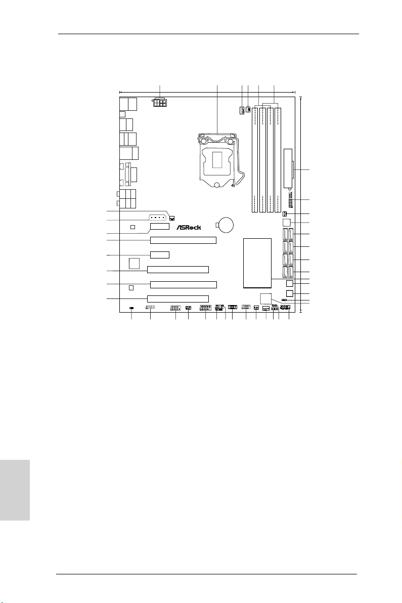
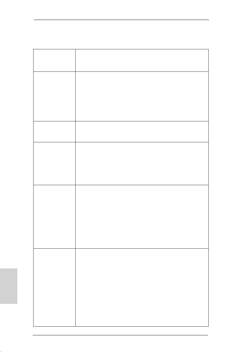
Motherboard Layout
Intel
Z77
DDR3_ A2 (64 bi t, 240- pin mod ule)
DDR3_ A1 (64 bi t, 240- pin mod ule)
DDR3_ B2 (64 bi t, 240- pin mod ule)
DDR3_ B1 (64 bi t, 240- pin mod ule)
ATX12V1
ATXPW R1
1
USB3_4_5
CPU_FAN1
CPU_FAN2
SLI/XFIRE_PWR1
SATA3_A1_A2
SATA3_0_1
SATA2_2_3
SATA2_4_5
64Mb
BIOS
CMOS
Battery
PCIE1
PCIE2
PCIE3
PCIE4
PCI1
PCI2
Super
I/O
Dr.
Debug
PWRBTN
RSTBTN
PLED1
1
HDLEDR ESET
PLEDPWRBTN
PANEL1
1
1
SPEAKER1
CLRCMOS1
1
CHA_FAN1
CHA_FAN3
USB4_5
1
1
USB2_3
USB6_7
1
CIR1
1
FRONT_1394
1
IR1
1
COM1
1
1
HD_AUDIO1
1
HDMI_SPDIF1
AUDIO
CODEC
LAN
PHY
PWR_FAN1
CHA_FAN2
USB 3.0
T: USB0
B: USB1
PS2
Keyboar d/
Mouse
Clr
CMOS
HDMI1
DP1
USB 2.0
T: USB0
B: USB1
IEEE 1394
eSATA_1
Top:
RJ-45
USB 3.0
T: USB2
B: USB3
VGA1
TB1
TB2
Top:
Central/Ba ss
Center:
REAR SPK
Top:
LINE IN
Center:
FRONT
Bottom:
Optical
SPDIF
Bottom:
MIC IN
Z77 Extreme6/TB4
PCI Express 3.0
Designed in Tai pei
RoHS
XFast LAN
XFast USB
XFast RAM
ErP/EuPReady
DDR3 2800+
Front U SB 3.0
1
2
3
4
5
6
7
8
9
10
24.4cm (9.6 in)
30.5 cm (12. 0 in)
11
12
13
14
16
17
15
18
19
20
21
22
23
24
25
26
27
28
29
30
31
32
33
34
35
36
37
38
39
40
41
English
1 ATX 12V Power Connector (ATX12V1)
2 1155-Pin CPU Socket
3 CPU Fan Connector (CPU_FAN1)
4 CPU Fan Connector (CPU_FAN2)
5 2 x 240-pin DDR3 DIMM Slots
(DDR3_A1, DDR3_B1, Black)
6 2 x 240-pin DDR3 DIMM Slots
(DDR3_A2, DDR3_B2, Black)
7 ATX Power Connector (ATXPWR1)
8 USB 3.0 Header (USB3_4_5, Black)
9 Power Fan Connector (PWR_FAN1)
10 SPI Flash Memory (64Mb)
11 SATA3 Connectors (SATA3_A1_A2, Gray)
12 SATA3 Connectors (SATA3_0_1, Gray)
13 SATA2 Connectors (SATA2_2_3, Black)
14 SATA2 Connectors (SATA2_4_5, Black)
15 Intel Z77 Chipset
16 Reset Switch (RSTBTN1)
17 Power Switch (PWRBTN1)
18 Power LED Header (PLED1)
19 Dr. Debug
20 System Panel Header (PANEL1, Black)
21 Clear CMOS Jumper (CLRCMOS1)
22 Chassis Speaker Header
(SPEAKER1, Black)
2
ASRock Z77 Extreme6/TB4 Motherboard
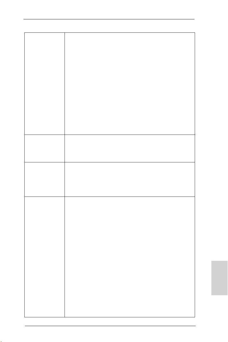
23 Chassis Fan Connector (CHA_FAN1)
24 Chassis Fan Connector (CHA_FAN3)
25 USB 2.0 Header (USB2_3, Black)
26 USB 2.0 Header (USB4_5, Black)
27 USB 2.0 Header (USB6_7, Black)
28 Consumer Infrared Module Header
(CIR1, Gray)
29 Front Panel IEEE 1394 Header
(FRONT_1394, Black)
30 Infrared Module Header (IR1)
31 COM Port Header (COM1)
32 Front Panel Audio Header
(HD_AUDIO1, Black)
33 HDMI_SPDIF Header
(HDMI_SPDIF1, Black)
34 PCI Slot (PCI2, Black)
35 PCI Express 3.0 x16 Slot (PCIE4, Black)
36 PCI Slot (PCI1, Black)
37 PCI Express 2.0 x1 Slot (PCIE3, Black)
38 PCI Express 3.0 x16 Slot (PCIE2, Black)
39 PCI Express 2.0 x1 Slot (PCIE1, Black)
40 SLI / XFIRE Power Connector
41 Chassis Fan Connector (CHA_FAN2)
Page 3
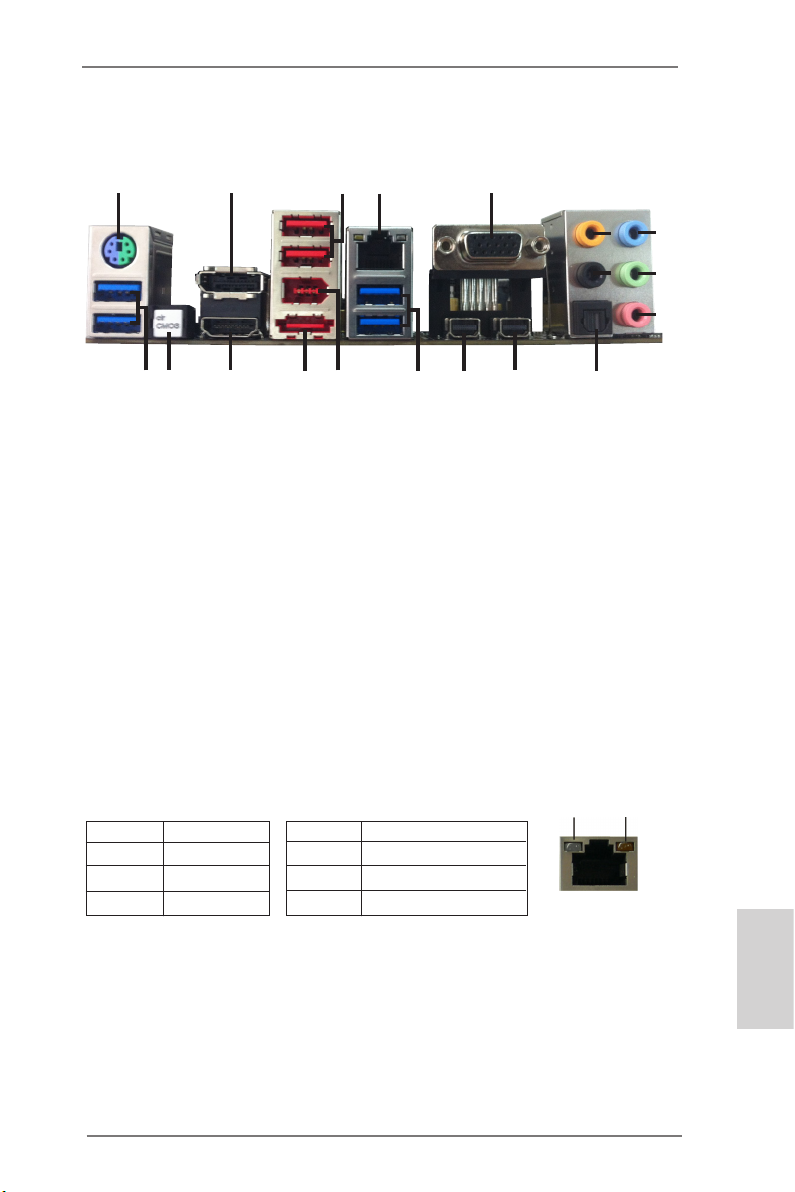
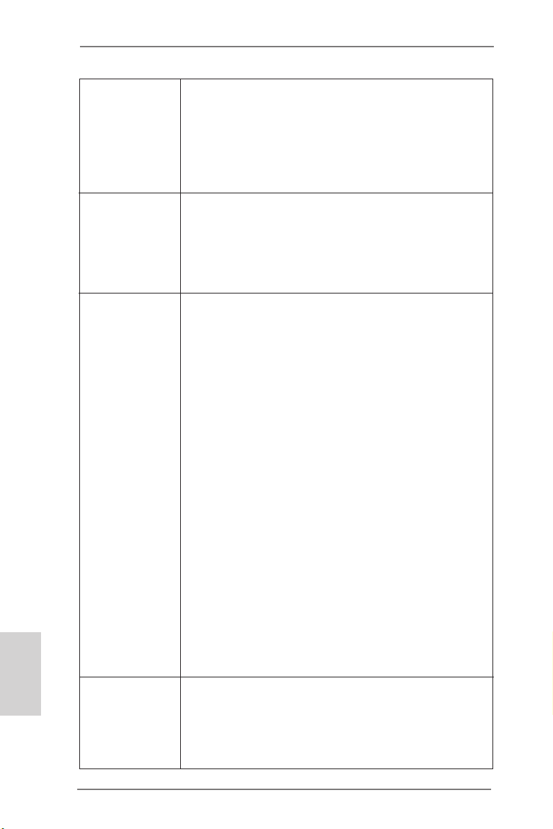
I/O Panel
1
2
4
3
5
8
6
9
7
10
19
18
1 PS/2 Keyboard/Mouse Port (Purple/Green)
* 2 DisplayPort Input (HDMI_DP_1)
3 USB 2.0 Ports (USB01)
** 4 LAN RJ-45 Port
5 D-Sub Port (VGA1)
6 Central / Bass (Orange)
7 Rear Speaker (Black)
8 Line In (Light Blue)
*** 9 Front Speaker (Lime)
10 Microphone (Pink)
DisplayPort Input for test only.
*
** There are two LED next to the LAN port. Please refer to the table below for the LAN port LED
indications.
Activity/Link LED SPEED LED
Status Description Status Description
17
LAN Port LED Indications
16
15
Off No Link Off 10Mbps connection
Blinking Data Activity Orange 100Mbps connection
On Link Green 1Gbps connection
14
11 Optical SPDIF Out Port
12 Thunderbolt Port (TBT1)
13 Thunderbolt Port (TBT2)
14 USB 3.0 Ports (USB3_23)
15 IEEE 1394 Port (1394)
**** 16 eSATA3 Connector
17 HDMI Port (HDMI1)
18 Clear CMOS Switch (CLRCBTN)
19 USB 3.0 Ports (USB3_01)
13
12
11
ACT/LINK
LED
LAN Port
SPEED
LED
ASRock Z77 Extreme6/TB4 Motherboard
English
3
Page 4
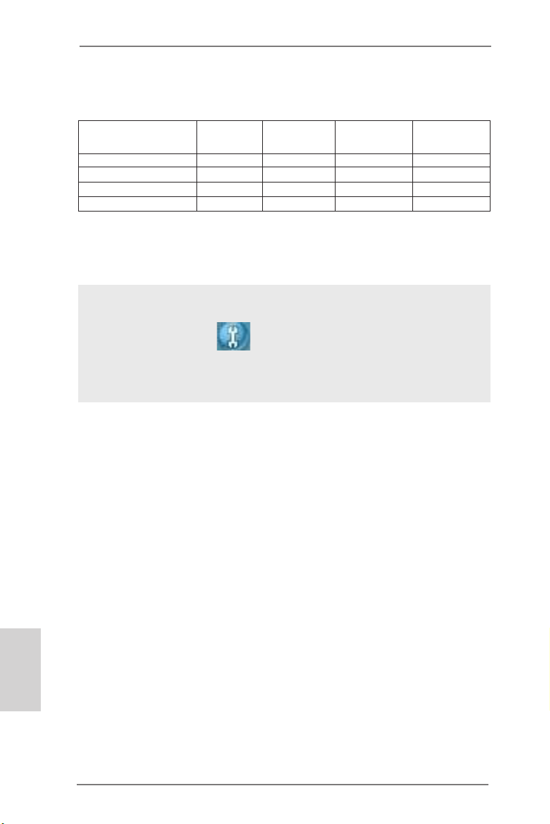
If you use 2-channel speaker, please connect the speaker’s plug into “Front Speaker Jack”.
***
See the table below for connection details in accordance with the type of speaker you use.
TABLE for Audio Output Connection
Audio Output Channels Front Speaker Rear Speaker Central / Bass Line in
(No. 9) (No. 7) (No. 6) (No. 8)
2 V -- -- -4 V V -- -6 V V V -8 V V V V
To enable Multi-Streaming function, you need to connect a front panel audio cable to the front
panel audio header. After restarting your computer, you will nd “Mixer” tool on your system.
Please select “Mixer ToolBox” , click “Enable playback multi-streaming”, and click
“ok”. Choose “2CH”, “4CH”, “6CH”, or “8CH” and then you are allowed to select “Realtek HDA
Primary output” to use Rear Speaker, Central/Bass, and Front Speaker, or select “Realtek HDA
Audio 2nd output” to use front panel audio.
**** eSATA3 connector supports SATA Gen3 in cable 1M.
English
4
ASRock Z77 Extreme6/TB4 Motherboard
Page 5
1: Introduction
Thank you for purchasing ASRock Z77 Extreme6/TB4 motherboard, a reliable
motherboard produced under ASRock’s consistently stringent quality control. It delivers excellent performance with robust design conforming to ASRock’s commitment
to quality and endurance.
In this manual, chapter 1 and 2 contains the introduction of the motherboard and
step-by-step hardware installation guide. Chapter 3 and 4 contains the conguration
guide of BIOS setup and information of the Support CD.
Because the motherboard specications and the BIOS software might be
updated, the content of this manual will be subject to change without no-
tice. In case any modications of this manual occur, the updated version
will be available on ASRock website without further notice. You may nd
the latest VGA cards and CPU support lists on ASRock website as well.
ASRock website http://www.asrock.com
If you require technical support related to this motherboard, please visit
our website for specic information about the model you are using.
www.asrock.com/support/index.asp
1.1 Package Contents
ASRock Z77 Extreme6/TB4 Motherboard
(ATX Form Factor: 12.0-in x 9.6-in, 30.5 cm x 24.4 cm)
ASRock Z77 Extreme6/TB4 Quick Installation Guide
ASRock Z77 Extreme6/TB4 Support CD
6 x Serial ATA (SATA) Data Cables (Optional)
1 x I/O Panel Shield
1 x ASRock SLI_Bridge_2S Card
ASRock Z77 Extreme6/TB4 Motherboard
English
5
Page 6
English
1.2 Specications
Platform - ATX Form Factor: 12.0-in x 9.6-in, 30.5 cm x 24.4 cm
- Premium Gold Capacitor design (100% Japan-made
high-quality Conductive Polymer Capacitors)
CPU - Supports 3rd and 2nd Generation Intel® CoreTM i7 / i5 / i3 in
LGA1155 Package
- Digi Power Design
- 8 + 4 Power Phase Design
- Supports Intel® Turbo Boost 2.0 Technology
- Supports Intel® K-Series unlocked CPU
- Supports Hyper-Threading Technology (see CAUTION 1)
Chipset - Intel® Z77
- Supports Intel® Rapid Start Technology and Smart Connect
Technology
Memory - Dual Channel DDR3 Memory Technology (see CAUTION 2)
- 4 x DDR3 DIMM slots
- Supports DDR3 2800+(OC)/2400(OC)/2133(OC)/1866(OC)/
1600/1333/1066 non-ECC, un-buffered memory
- Max. capacity of system memory: 32GB (see CAUTION 3)
- Supports Intel® Extreme Memory Prole (XMP)1.3/1.2
Expansion Slots - 2 x PCI Express 3.0 x16 slots (PCIE2/PCIE4: single at x16
(PCIE2) / x8 (PCIE4) or dual at x8/x8 mode)
(see CAUTION 4)
* PCIE 3.0 is only supported with Intel® Ivy Bridge CPU. With
Intel® Sandy Bridge CPU, it only supports PCIE 2.0.
- 2 x PCI Express 2.0 x 1 slots
- 2 x PCI slots
- Supports AMD Quad CrossFireXTM and CrossFireX
- Supports NVIDIA® Quad SLITM and SLI
TM
Graphics * Intel® HD Graphics Built-in Visuals and the VGA outputs can
be supported only with processors which are GPU
integrated.
- Supports Intel® HD Graphics Built-in Visuals: Intel® Quick
Sync Video 2.0, Intel® InTruTM 3D, Intel® Clear Video HD
Technology, Intel® InsiderTM and Intel® HD Graphics
2500/4000
- Pixel Shader 5.0, DirectX 11 with Intel® Ivy Bridge CPU.
Pixel Shader 4.1, DirectX 10.1 with Intel® Sandy Bridge CPU
- Max. shared memory 1760MB (see CAUTION 5)
- Three VGA Output options: D-Sub, HDMI and Thunderbolt
TM
6
ASRock Z77 Extreme6/TB4 Motherboard
Page 7
ports (see CAUTION 6)
- Supports HDMI 1.4a Technology with max. resolution up to
1920x1200 @ 60Hz
- Supports D-Sub with max. resolution up to 2048x1536 @
75Hz
- Supports Thunderbolt with max. resolution up to 2560x1600
@ 60Hz
- Supports Auto Lip Sync, Deep Color (12bpc), xvYCC and
HBR (High Bit Rate Audio) with HDMI (see CAUTION 7)
- Supports HDCP function with HDMI
- Supports Full HD 1080p Blu-ray (BD) / HD-DVD playback
with HDMI
- Supports data transfer rate up to 10Gbps with Thunderbolt
port
- Supports Daisy-chain up to 6 Thunderbolt devices
Audio - 7.1 CH HD Audio with Content Protection
(Realtek ALC898 Audio Codec)
- Premium Blu-ray audio support
- Supports THX TruStudio
TM
LAN - PCIE x1 Gigabit LAN 10/100/1000 Mb/s
- Broadcom BCM57781
- Supports Wake-On-LAN
- Supports Energy Efcient Ethernet 802.3az
- Supports PXE
Rear Panel I/O I/O Panel
- 1 x PS/2 Mouse/Keyboard Port
- 1 x D-Sub Port
- 1 x HDMI Port
- 1 x DisplayPort Input for Thunderbolt port (TBT2 for test
only)
- 2 x Thunderbolt Ports
- 1 x Optical SPDIF Out Port
- 2 x Ready-to-Use USB 2.0 Ports
- 1 x eSATA3 Connector
- 4 x Ready-to-Use USB 3.0 Ports
- 1 x RJ-45 LAN Port with LED (ACT/LINK LED and SPEED
LED)
- 1 x IEEE 1394 Port
- 1 x Clear CMOS Switch with LED
- HD Audio Jack: Rear Speaker/Central/Bass/Line in/Front
Speaker/Microphone (see CAUTION 8)
English
ASRock Z77 Extreme6/TB4 Motherboard
7
Page 8
English
SATA 3 - 2 x SATA3 6.0 Gb/s connectors by Intel® Z77, support RAID
(RAID 0, RAID 1, RAID 5, RAID 10, Intel Rapid Storage and
Intel Smart Response Technology), NCQ, AHCI and Hot
Plug
- 2 x SATA3 6.0 Gb/s connectors by ASMedia ASM1061,
support NCQ, AHCI and Hot Plug (SATA3_A2 connector is
shared with the eSATA port)
USB3.0 - 2 x Rear USB 3.0 ports by Intel® Z77, support USB
1.1/2.0/3.0 up to 5Gb/s
- 2 x Rear USB 3.0 ports by ASMedia ASM1042, support USB
1.1/2.0/3.0 up to 5Gb/s
- 1 x Front USB 3.0 header by Intel® Z77 (supports 2 USB 3.0
ports), supports USB 1.1/2.0/3.0 up to 5Gb/s
Connectors - 4 x SATA2 3.0 Gb/s connectors, support RAID (RAID 0,
RAID 1, RAID 5, RAID 10, Intel Rapid Storage and Intel
Smart Response Technology), NCQ, AHCI and Hot Plug
- 1 x IR header
- 1 x CIR header
- 1 x COM port header
- 1 x HDMI_SPDIF header
- 1 x IEEE 1394 header
- 1 x Power LED header
- 2 x CPU Fan connectors (1 x 4-pin, 1 x 3-pin)
- 3 x Chassis Fan connectors (1 x 4-pin, 2 x 3-pin)
- 1 x Power Fan connector (3-pin)
- 24 pin ATX power connector
- 8 pin 12V power connector
- SLI/XFire power connector
- Front panel audio connector
- 3 x USB 2.0 headers (support 6 USB 2.0 ports)
- 1 x USB 3.0 header (supports 2 USB 3.0 ports)
- 1 x Dr. Debug with LED
- 1 x Clear CMOS Switch with LED
- 1 x Power Switch with LED
- 1 x Reset Switch with LED
BIOS Features - 64Mb AMI UEFI Legal BIOS with GUI support
- Supports “Plug and Play”
- ACPI 1.1 Compliance Wake Up Events
- Supports jumperfree
- SMBIOS 2.3.1 Support
- 4 x SATA3 6.0Gb/s connectors
8
ASRock Z77 Extreme6/TB4 Motherboard
Page 9
- CPU Core, IGPU, DRAM, 1.8V PLL, VTT, VCCSA Voltage
Multi-adjustment
Support CD - Drivers, Utilities, AntiVirus Software (Trial Version),
CyberLink MediaEspresso 6.5 Trial, ASRock MAGIX
Multimedia Suite - OEM, Google Chrome Browser and
Toolbar
Unique Features - ASRock Extreme Tuning Utility (AXTU) (see CAUTION 9)
- ASRock Instant Boot
- ASRock Instant Flash (see CAUTION 10)
- ASRock APP Charger (see CAUTION 11)
- ASRock SmartView (see CAUTION 12)
- ASRock XFast USB (see CAUTION 13)
- ASRock XFast LAN (see CAUTION 14)
- ASRock XFast RAM (see CAUTION 15)
- ASRock Crashless BIOS (see CAUTION 16)
- Lucid Virtu Universal MVP (see CAUTION 17)
* Lucid Virtu Universal MVP can be supported only with
processors which are GPU integrated.
- ASRock OMG (Online Management Guard)
(see CAUTION 18)
- ASRock Internet Flash (see CAUTION 19)
- ASRock UEFI System Browser
- ASRock Dehumider Function (see CAUTION 20)
- ASRock Fast Boot
- ASRock Restart to UEFI
- Hybrid Booster:
- CPU Frequency Stepless Control (see CAUTION 21)
- ASRock U-COP (see CAUTION 22)
- Boot Failure Guard (B.F.G.)
- Good Night LED
Hardware - CPU/Chassis Temperature Sensing
Monitor - CPU/Chassis/Power Fan Tachometer
- CPU/Chassis Quiet Fan (Allows Chassis Fan Speed Auto Adjust by CPU Temperature)
- CPU/Chassis Fan Multi-Speed Control
- Voltage Monitoring: +12V, +5V, +3.3V, CPU Vcore
OS - Microsoft® Windows® 8 / 8 64-bit / 7 / 7 64-bit / VistaTM /
VistaTM 64-bit / XP / XP 64-bit compliant (see CAUTION 23)
Certications - FCC, CE, WHQL
- ErP/EuP Ready (ErP/EuP ready power supply is required)
(see CAUTION 24)
* For detailed product information, please visit our website: http://www.asrock.com
ASRock Z77 Extreme6/TB4 Motherboard
English
9
Page 10

English
WARNING
Please realize that there is a certain risk involved with overclocking, including
adjusting the setting in the BIOS, applying Untied Overclocking Technology, or using
third-party overclocking tools. Overclocking may affect your system’s stability, or
even cause damage to the components and devices of your system. It should be
done at your own risk and expense. We are not responsible for possible damage
caused by overclocking.
CAUTION!
1. About the settings of “Hyper Threading Technology”, please check page
65 of the “User Manual” in the support CD.
2. This motherboard supports Dual Channel Memory Technology. Before
you implement Dual Channel Memory Technology, make sure to read the
installation guide of memory modules on page 18 for proper installation.
3. Due to the operating system limitation, the actual memory size may be
less than 4GB for the reservation for system usage under Windows® 8 /
7 / VistaTM / XP. For 64-bit Windows® OS there is no such limitation. You
can use ASRock XFast RAM to utilize the memory that Windows® cannot
use.
4. Only PCIE2 and PCIE4 slots support Gen 3 speed. To run the PCI Express in Gen 3 speed, please install an Ivy Bridge CPU. If you install a
Sandy Bridge CPU, the PCI Express will run only at PCI Express Gen 2
speed.
5. The maximum shared memory size is dened by the chipset vendor and
is subject to change. Please check Intel® website for the latest information.
6. You can choose to use two of the three monitors only. D-Sub, HDMI and
Thunderbolt monitors cannot be enabled at the same time.
7. xvYCC and Deep Color are only supported under Windows® 8 64-bit / 8 /
7 64-bit / 7. Deep Color mode will be enabled only if the display supports
12bpc in EDID. HBR is supported under Windows® 8 64-bit / 8 / 7 64-bit /
7 / VistaTM 64-bit / VistaTM.
8. For microphone input, this motherboard supports both stereo and mono
modes. For audio output, this motherboard supports 2-channel, 4-channel, 6-channel, and 8-channel modes. Please check the table on page 3
for proper connection.
9. ASRock Extreme Tuning Utility (AXTU) is an all-in-one tool to ne-tune different system functions in a user-friendly interface, which includes Hardware Monitor, Fan Control, Overclocking, OC DNA and IES. In Hardware
Monitor, it shows the major readings of your system. In Fan Control, it
shows the fan speed and temperature for you to adjust. In Overclocking,
10
ASRock Z77 Extreme6/TB4 Motherboard
Page 11
you are allowed to overclock CPU frequency for optimal system per-
formance. In OC DNA, you can save your OC settings as a prole and
share it with your friends. Your friends then can load the OC prole to
their own system to get the same OC settings. In IES (Intelligent Energy
Saver), the voltage regulator can reduce the number of output phases to
improve efciency when the CPU cores are idle without sacricing computing performance. Please visit our website for the operation procedures
of ASRock Extreme Tuning Utility (AXTU).
ASRock website: http://www.asrock.com
10. ASRock Instant Flash is a BIOS ash utility embedded in Flash ROM.
This convenient BIOS update tool allows you to update system BIOS
without entering operating systems rst like MS-DOS or Windows®. With
this utility, you can press the <F6> key during the POST or the <F2>
key to enter into the BIOS setup menu to access ASRock Instant Flash.
Just launch this tool and save the new BIOS le to your USB ash drive,
oppy disk or hard drive, then you can update your BIOS only in a few
clicks without preparing an additional oppy diskette or other complicated
ash utility. Please be noted that the USB ash drive or hard drive must
use FAT32/16/12 le system.
11. If you desire a faster, less restricted way of charging your Apple devices,
such as iPhone/iPad/iPod Touch, ASRock has prepared a wonderful solution for you - ASRock APP Charger. Simply install the APP Charger
driver, it makes your iPhone charge much quickly from your computer
and up to 40% faster than before. ASRock APP Charger allows you to
quickly charge many Apple devices simultaneously and even supports
continuous charging when your PC enters into Standby mode (S1), Suspend to RAM (S3), hibernation mode (S4) or power off (S5). With APP
Charger driver installed, you can easily enjoy the marvelous charging
experience.
ASRock website: http://www.asrock.com/Feature/AppCharger/index.asp
12. ASRock SmartView, a new function for internet browsers, is the smart
start page for IE that combines your most visited web sites, your history,
your Facebook friends and your real-time newsfeed into an enhanced
view for a more personal Internet experience. ASRock motherboards are
exclusively equipped with the ASRock SmartView utility that helps you
keep in touch with friends on-the-go. To use ASRock SmartView feature,
please make sure your OS version is Windows® 8 / 8 64-bit / 7 / 7 64-bit /
VistaTM / VistaTM 64 bit, and your browser version is IE8.
ASRock website: http://www.asrock.com/Feature/SmartView/index.asp
13. ASRock XFast USB can boost USB storage device performance. The
performance may depend on the properties of the device.
14. ASRock XFast LAN provides a faster internet access, which includes the
benets listed below. LAN Application Prioritization: You can congure
your application’s priority ideally and/or add new programs. Lower Latency in Game: After setting online game’s priority higher, it can lower the
latency in games. Trafc Shaping: You can watch Youtube HD videos and
English
ASRock Z77 Extreme6/TB4 Motherboard
11
Page 12

English
download simultaneously. Real-Time Analysis of Your Data: With the sta-
tus window, you can easily recognize which data streams you are transferring currently.
15. ASRock XFast RAM is a new function that is included into ASRock Ex-
treme Tuning Utility (AXTU). It fully utilizes the memory space that cannot
be used under Windows® OS 32-bit CPU. ASRock XFast RAM shortens
the loading time of previously visited websites, making web surng faster
than ever. And it also boosts the speed of Adobe Photoshop 5 times
faster. Another advantage of ASRock XFast RAM is that it reduces the
frequency of accessing your SSDs or HDDs in order to extend their lifespan.
16. ASRock Crashless BIOS allows users to update their BIOS without fear
of failing. If power loss occurs during the BIOS update process, ASRock
Crashless BIOS will automatically nish the BIOS update procedure after
regaining power. Please note that BIOS les need to be placed in the
root directory of your USB disk. Only USB2.0 ports support this feature.
17. VIRTU Universal MVP includes the base features of Virtu Universal
technology, which virtualizes integrated GPU and discrete GPU for best
of breed functionality. It also features Virtual Vsync™ for no-compromise
visual quality. With the added benefits of HyperFormance technology,
VIRTU Universal MVP improves game performance by intelligently re-
ducing redundant rendering tasks in the ow between the CPU, GPU and
the display.
18. Administrators are able to establish an internet curfew or restrict internet
access at specied times via OMG. You may schedule the starting and
ending hours of internet access granted to other users. In order to prevent users from bypassing OMG, guest accounts without permission to
modify the system time are required.
19. Internet Flash searches for available UEFI rmware updates from our
servers. In other words, the system can auto-detect the latest UEFI from
our servers and ash them without entering Windows OS. Please note
that you must be running on a DHCP congured computer in order to en-
able this function.
20. Users may prevent motherboard damages due to dampness by enabling
“Dehumidier Function”. When enabling Dehumidier Function, the computer will power on automatically to dehumidify the system after entering
S4/S5 state.
21. Although this motherboard offers stepless control, it is not recommended
to perform over-clocking. Frequencies other than the recommended CPU
bus frequencies may cause instability of the system or damage the CPU.
22. While CPU overheat is detected, the system will automatically shutdown.
Before you resume the system, please check if the CPU fan on the motherboard functions properly and unplug the power cord, then plug it back
again. To improve heat dissipation, remember to spray thermal grease
between the CPU and the heatsink when you install the PC system.
23. ASRock XFast RAM is not supported by Microsoft® Windows® XP / XP
12
ASRock Z77 Extreme6/TB4 Motherboard
Page 13

64-bit. Intel® Smart Connect Technology and Intel® USB 3.0 ports are not
supported by Microsoft® Windows® VistaTM / VistaTM 64-bit / XP / XP 64bit.
24. EuP stands for Energy Using Product, was a provision regulated by the
European Union to define the power consumption for the completed
system. According to EuP, the total AC power of the completed system
should be under 1.00W in off mode condition. To meet EuP standards,
an EuP ready motherboard and an EuP ready power supply are required.
According to Intel’s suggestion, the EuP ready power supply must meet
the standard of 5v, and the standby power efciency should be higher
than 50% under 100 mA current consumption. For EuP ready power supply selection, we recommend you to check with the power supply manufacturer for more details.
ASRock Z77 Extreme6/TB4 Motherboard
English
13
Page 14

2: Installation
This is an ATX form factor (12.0" x 9.6", 30.5 x 24.4 cm) motherboard. Before you
install the motherboard, study the conguration of your chassis to ensure that the
motherboard ts into it.
2.1 Pre-installation Precautions
Take note of the following precautions before you install motherboard components
or change any motherboard settings.
1. Make sure to unplug the power cord before installing or removing
the motherboard. Failure to do so may cause physical injuries to
you and damages to motherboard components.
2. In order to avoid damage from static electricity to the motherboard’s
components, NEVER place your motherboard directly on a carpet.
Also remember to use a grounded wrist strap or touch a safety
grounded object before you handle the components.
3. Hold components by the edges and do not touch the ICs.
4. Whenever you uninstall any components, place them on a grounded
anti-static pad or in the bag that comes with the components.
5. When placing screws to secure the motherboard to the chassis,
please do not over-tighten the screws! Doing so may damage the
motherboard.
2.2 Screw Holes
Place screws into the holes indicated by circles to secure the motherboard to the
chassis.
English
14
ASRock Z77 Extreme6/TB4 Motherboard
Page 15
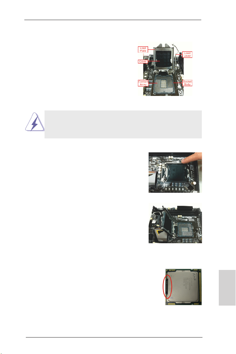
2.3 CPU Installation
In order to provide the LGA 1155 CPU sockets more protection and make the installation process easier, ASRock has added
a new protection cover on top of the load
plate to replace the former PnP caps that
were under the load plate. For the installation of Intel® 1155-Pin CPUs with the new
protection cover, please follow the steps
below.
Before you insert the 1155-Pin CPU into the socket, please check if the
CPU surface is unclean or if there are any bent pins in the socket. Do
not force to insert the CPU into the socket if above situation is found.
Otherwise, the CPU will be seriously damaged.
Step 1. Open the socket:
Step 1-1. Disengage the lever by pressing it
down and sliding it out of the hook.
You do not have to remove the protection cover.
Step 1-2. Keep the lever positioned at about
135 degrees in order to flip up the
load plate.
1155-Pin Socket Overview
Step 2. Insert the 1155-Pin CPU:
Step 2-1. Hold the CPU by the edge which is
marked with a black line.
Step 2-2. Orient the CPU with the IHS (Inte-
grated Heat Sink) up. Locate Pin1
and the two orientation key notches.
ASRock Z77 Extreme6/TB4 Motherboard
black line
English
15
Page 16
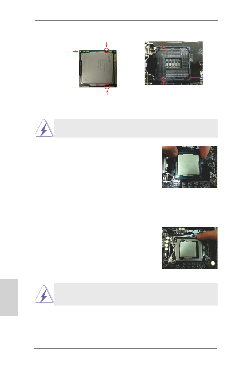
orientation key notch
Pin1
orientation key notch
1155-Pin CPU
For proper installation, please ensure to match the two orientation
key notches of the CPU with the two alignment keys of the socket.
alignment key
alignment key
Step 2-3. Carefully place the CPU into the
socket.
Step 2-4. Verify that the CPU is within the sock-
et and properly mated to the orient
keys.
Pin1
1155-Pin Socket
English
16
Step 3. Close the socket:
Step 3-1. Flip the load plate onto the IHS.
Step 3-2. Press down the load lever, and se-
cure it with the load plate tab under
the retention tab. The protection
cover will automatically come off by
itself.
Please save and replace the cover if the processor is removed. The
cover must be placed if you wish to return the motherboard for after
service.
ASRock Z77 Extreme6/TB4 Motherboard
Page 17
2.4 Installation of CPU Fan and Heatsink
This motherboard is equipped with 1155-Pin socket that supports Intel 1155-Pin
CPUs. Please adopt the type of heatsink and cooling fan compliant with Intel 1155Pin CPU to dissipate heat. Before you install the heatsink, you need to spray thermal interface material between the CPU and the heatsink to improve heat dissipation. Ensure that the CPU and the heatsink are securely fastened and in good contact with each other. Then connect the CPU fan to the CPU_FAN connector (CPU_
FAN1, see p.2, No. 3 or CPU_FAN2, see p.2, No. 4).
For proper installation, please kindly refer to the instruction manuals of your
CPU fan and heatsink.
Below is an example to illustrate the installation of
the heatsink for 1155-Pin CPUs.
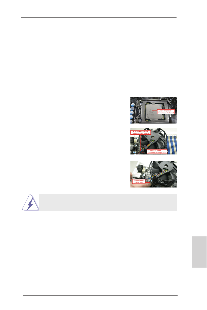
Step 1. Apply thermal interface material onto the cen-
ter of the IHS on the socket’s surface.
Step 2. Place the heatsink onto the socket. Ensure
that the fan cables are faced on the side closest to the CPU fan connector on the motherboard (CPU_FAN1, see p.2, No. 3 or CPU_
FAN3, see p.2, No. 4).
Step 3. Align fasteners with the motherboard through-
holes.
Step 4. Rotate the fastener clockwise, then press the
fastener caps down with your thumb to install
and lock. Repeat with remaining fasteners.
If you press down the fasteners without rotating them clockwise, the
heatsink cannot be secured on the motherboard.
Step 5. Connect CPU fan connector with the fan header on the motherboard.
Step 6. Secure redundant cable with tie-wrap to ensure that the cable does not
interfere with the fan’s operation or contact other components.
ASRock Z77 Extreme6/TB4 Motherboard
English
17
Page 18
English
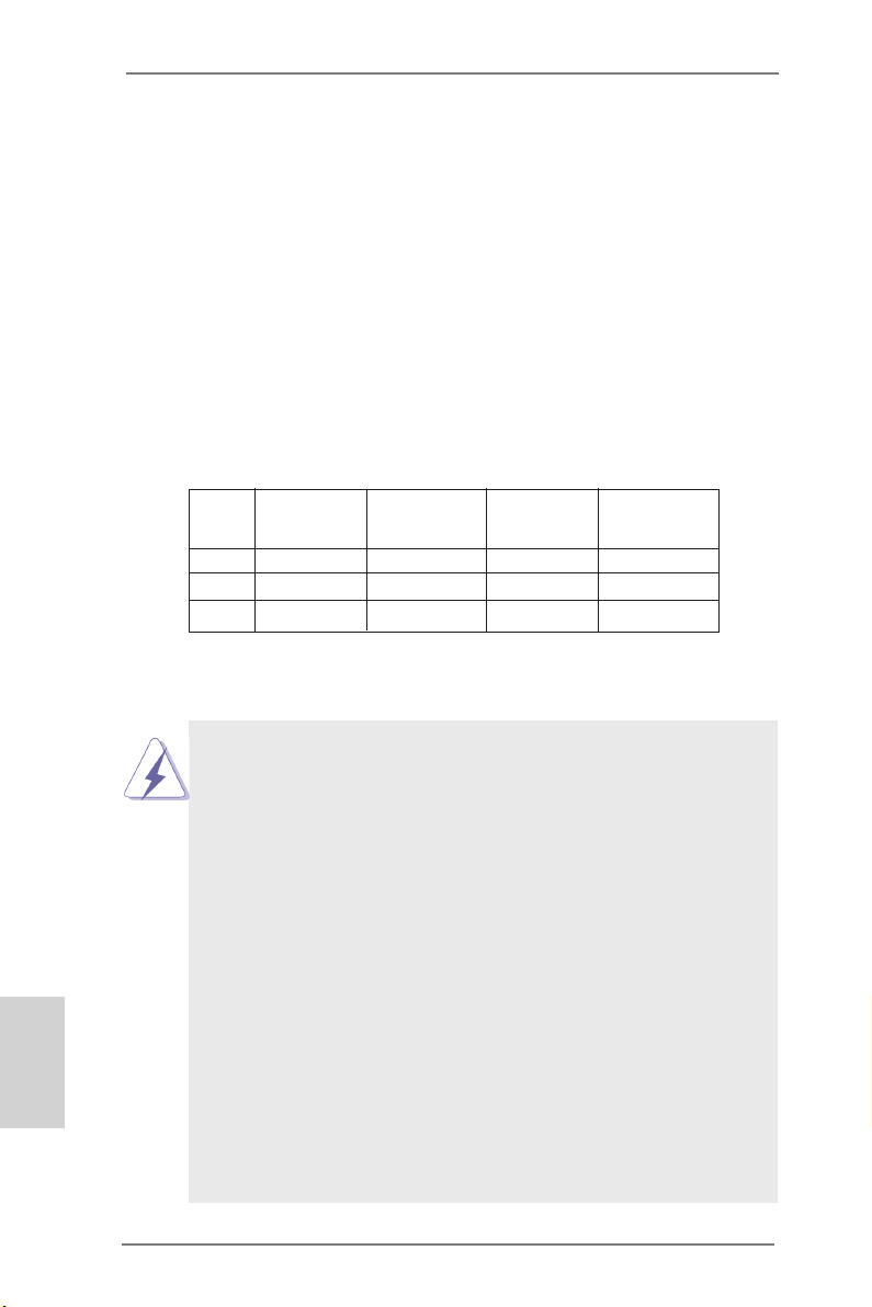
2.5 Installation of Memory Modules (DIMM)
This motherboard provides four 240-pin DDR3 (Double Data Rate 3) DIMM
slots, and supports Dual Channel Memory Technology. For dual channel conguration, you always need to install identical (the same brand, speed, size
and chip-type) DDR3 DIMM pair in the slots: You have to install identical
DDR3 DIMMs in Dual Channel A (DDR3_A1 and DDR3_B1; Black slots; see p.2
No. 5) or identical DDR3 DIMMs in Dual Channel B (DDR3_A2 and DDR3_
B2; Black slots; see p.2 No. 6), so that Dual Channel Memory Technology can
be activated. This motherboard also allows you to install four DDR3 DIMMs
for dual channel conguration, please install identical DDR3 DIMMs in all four
slots. You may refer to the Dual Channel Memory Conguration Table below.
Dual Channel Memory Conguration
DDR3_A1 DDR3_A2 DDR3_B1 DDR3_B2
(Black Slot) (Black Slot) (Black Slot) (Black Slot)
(1) Populated - Populated (2) - Populated - Populated
(3)* Populated Populated Populated Populated
* For conguration (3), please install identical DDR3 DIMMs in all four
slots.
1. If you want to install two memory modules, for optimal compatibility
and reliability, it is recommended to install them in the slots: DDR3_
A1 and DDR3_B1, or DDR3_A2 and DDR3_B2.
2. If only one memory module or three memory modules are installed
in the DDR3 DIMM slots on this motherboard, it is unable to activate
Dual Channel Memory Technology.
3. If a pair of memory modules is NOT installed in the same Dual
Channel, for example, installing a pair of memory modules in
DDR3_A1 and DDR3_A2, it is unable to activate Dual Channel
Memory Technology.
4. It is not allowed to install a DDR or DDR2 memory module into
DDR3 slot; otherwise, this motherboard and DIMM may be damaged.
5. Some DDR3 1GB double-sided DIMMs with 16 chips may not work
on this motherboard. It is not recommended to install them on this
motherboard.
6. For optimal compatibility and stability while overclocking memory
frequency, it is recommended to install one memory module in
DDR3_B2 slot or two memory modules in DDR3_A2 and DDR3_B2
slots.
18
ASRock Z77 Extreme6/TB4 Motherboard
Page 19
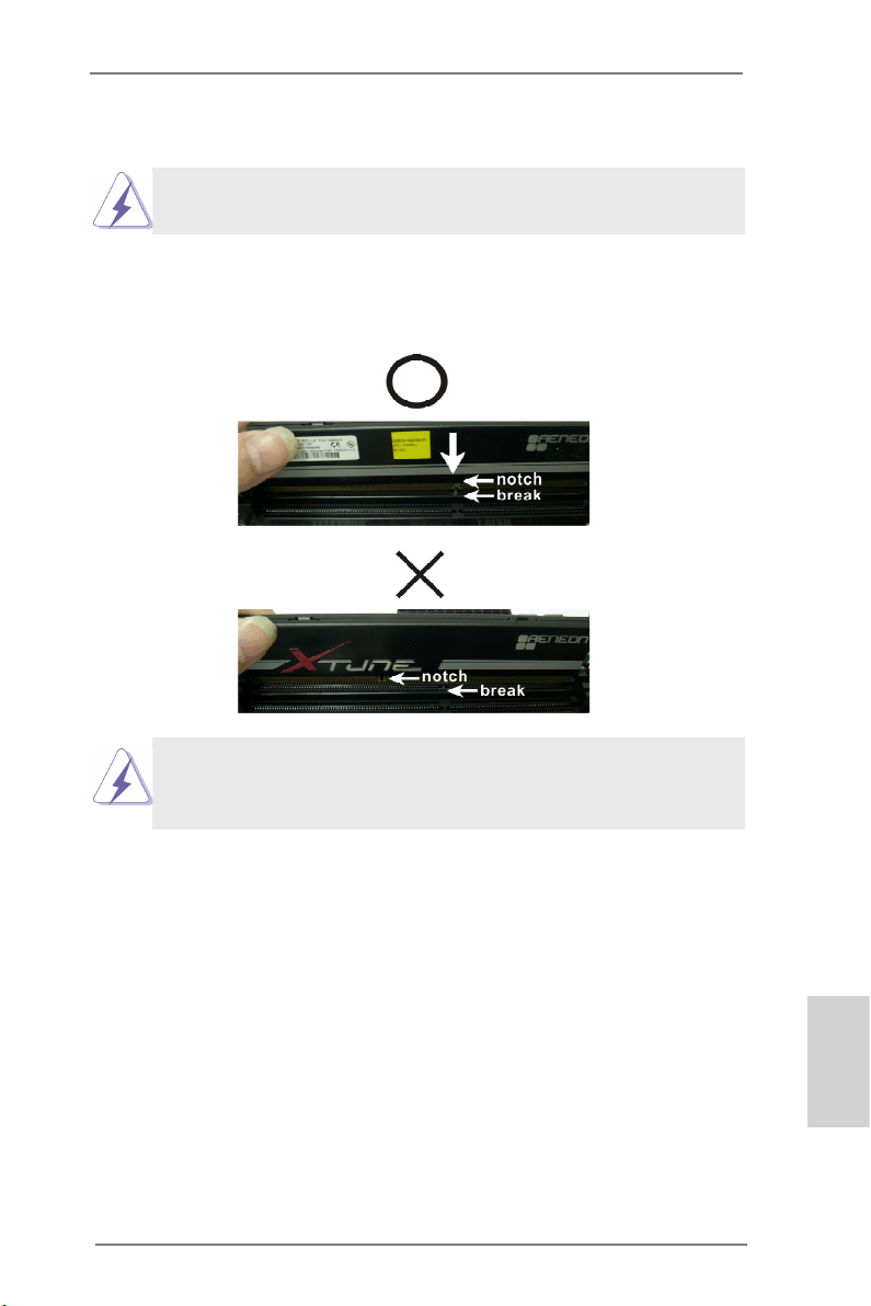
Installing a DIMM
Please make sure to disconnect power supply before adding or
removing DIMMs or the system components.
Step 1. Unlock a DIMM slot by pressing the retaining clips outward.
Step 2. Align a DIMM on the slot such that the notch on the DIMM matches the
break on the slot.
The DIMM only ts in one correct orientation. It will cause permanent
damage to the motherboard and the DIMM if you force the DIMM into
the slot in incorrect orientation.
Step 3. Firmly insert the DIMM into the slot until the retaining clips at both ends
fully snap back in place and the DIMM is properly seated.
ASRock Z77 Extreme6/TB4 Motherboard
English
19
Page 20
2.6 Expansion Slots (PCI and PCI Express Slots)
There are 2 PCI slots and 4 PCI Express slots on this motherboard.
PCI slots: PCI slots are used to install expansion cards that have 32-bit PCI
interface.
PCIE slots: PCIE1 and PCIE3 (PCIE 2.0 x1 slots) are used for PCI Express x1 lane
width cards, such as a Gigabit LAN card, SATA2 card
, etc.
PCIE2 (PCIE 3.0 x16 slot) is used for PCI Express x16 lane width
graphics cards, or used to install PCI Express graphics cards to support
CrossFireXTM or SLITM function.
PCIE4 (PCIE 3.0 x16 slot) is used for PCI Express x8 lane width graph-
ics cards, or used to install PCI Express graphics cards to support
CrossFireXTM or SLITM function.
1. In single VGA card mode, it is recommended to install a PCI Express
x16 graphics card on PCIE2 slot.
2. In CrossFireXTM mode or SLITM mode, please install the PCI Express
x16 graphics cards on PCIE2 and PCIE4 slots. Therefore, PCIE2 will
work at x8 bandwidth, while PCIE4 works at x8 bandwidth.
3. Please connect a chassis fan to the motherboard’s chassis fan
connector (CHA_FAN1, CHA_FAN2 or CHA_FAN3) when using
multiple graphics cards for better thermal environment.
4. Only PCIE2 and PCIE4 slots support Gen 3 speed. To run the PCI
Express in Gen 3 speed, please install an Ivy Bridge CPU. If you
install a Sandy Bridge CPU, the PCI Express will run only at PCI
Express Gen 2 speed.
English
20
Installing an expansion card
Step 1. Before installing an expansion card, please make sure that the power
supply is switched off or the power cord is unplugged. Please read the
documentation of the expansion card and make necessary hardware
settings for the card before you start the installation.
Step 2. Remove the system unit cover (if your motherboard is already installed
in a chassis).
Step 3. Remove the bracket facing the slot that you intend to use. Keep the
screws for later use.
Step 4. Align the card connector with the slot and press rmly until the card is
completely seated on the slot.
Step 5. Fasten the card to the chassis with screws.
Step 6. Replace the system cover
ASRock Z77 Extreme6/TB4 Motherboard
Page 21
2.7 SLITM and Quad SLI
TM
Operation Guide
This motherboard supports NVIDIA® SLITM and Quad SLITM (Scalable Link Interface)
technology that allows you to install up to two identical PCI Express x16 graphics
cards. Currently, NVIDIA® SLITM technology supports all Windows® OS. NVIDIA®
Quad SLITM technology supports Windows® VistaTM / 7 / 8 OS only. Please follow the
installation procedures in this section.
Requirements
1. For SLITM technology, you should have two identical SLITM-ready graphics
cards that are NVIDIA® certied. For Quad SLI technology, you should have
two identical Quad SLI ready graphics cards (dual-GPU on each graphics
card) that are NVIDIA certied.
2. Make sure that your graphics card driver supports NVIDIA® SLITM technology.
Download the driver from NVIDIA® website (www.nvidia.com).
3. Make sure that your power supply unit (PSU) can provide at least the
minimum power required by your system. It is recommended to use NVIDIA®
certied PSU. Please refer to NVIDIA® website for details.
2.7.1 Graphics Card Setup
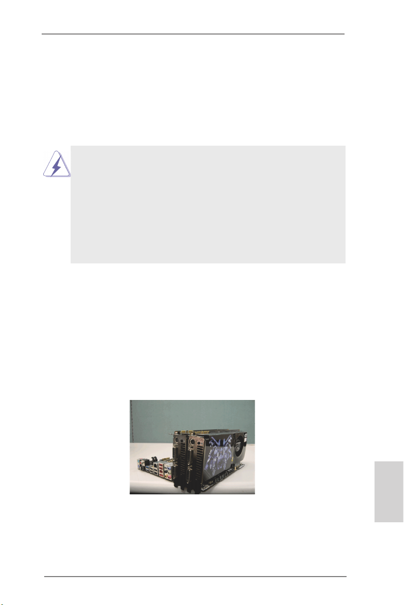
2.7.1.1 Installing Two SLITM-Ready Graphics Cards
Step 1. Install the identical SLITM-ready graphics cards that are NVIDIA® certied
because different types of graphics cards will not work together properly.
(Even the GPU chips version shall be the same.) Insert one graphics card
into PCIE2 slot and the other graphics card to PCIE4 slot. Make sure that
the cards are properly seated on the slots.
Step2. If required, connect the auxiliary power source to the PCI Express
graphics cards.
ASRock Z77 Extreme6/TB4 Motherboard
English
21
Page 22
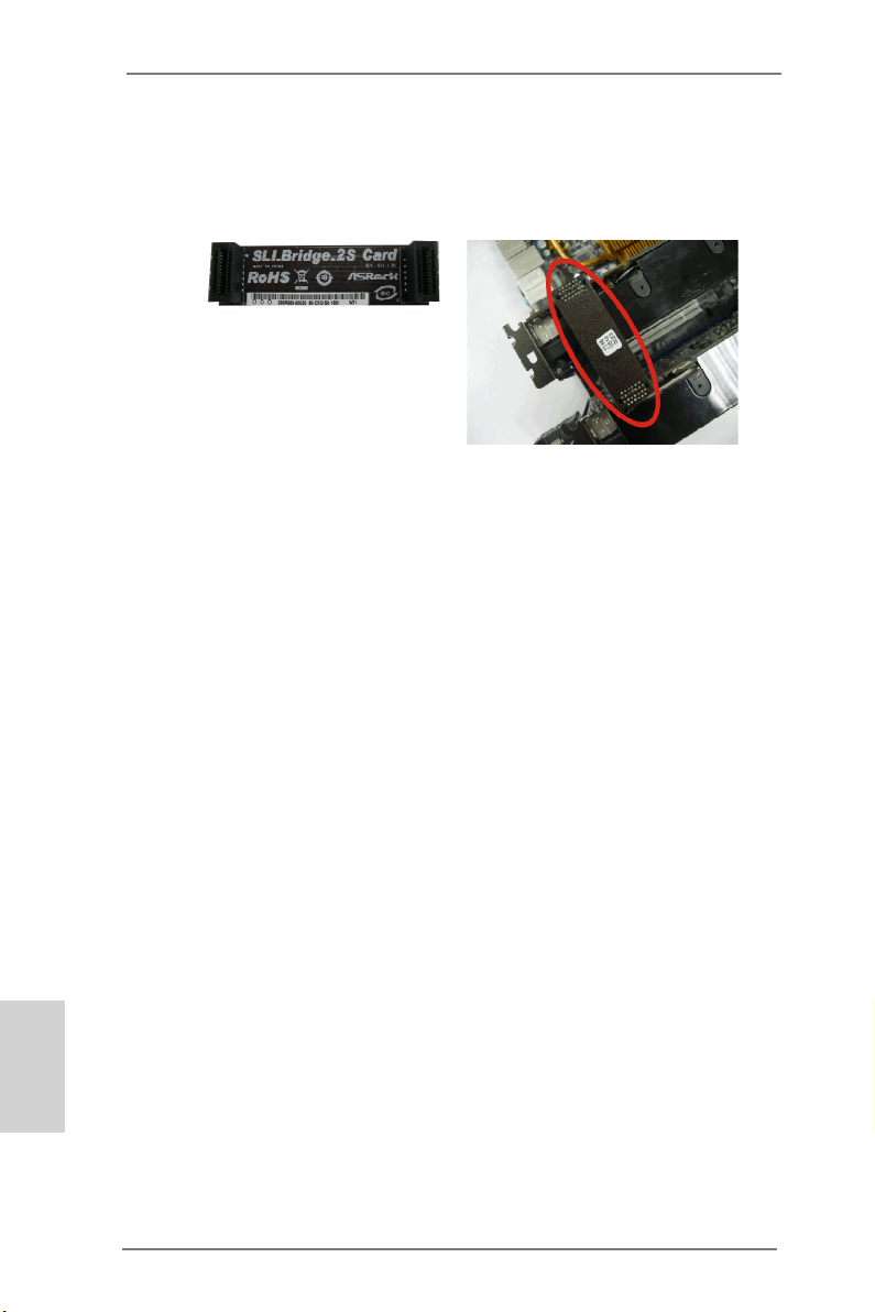
Step3. Align and insert the ASRock SLI_Bridge_2S Card to the goldngers on
each graphics card. Make sure the ASRock SLI_Bridge_2S Card is rmly
in place.
ASRock SLI_Bridge_2S Card
Step4. Connect a VGA cable or a DVI cable to the monitor connector or the DVI
connector of the graphics card that is inserted into PCIE2 slot.
English
22
ASRock Z77 Extreme6/TB4 Motherboard
Page 23
2.7.2 Driver Installation and Setup
Install the graphics card drivers to your system. After that, you can enable the MultiGraphics Processing Unit (GPU) feature in the NVIDIA® nView system tray utility.
Please follow the below procedures to enable the multi-GPU feature.
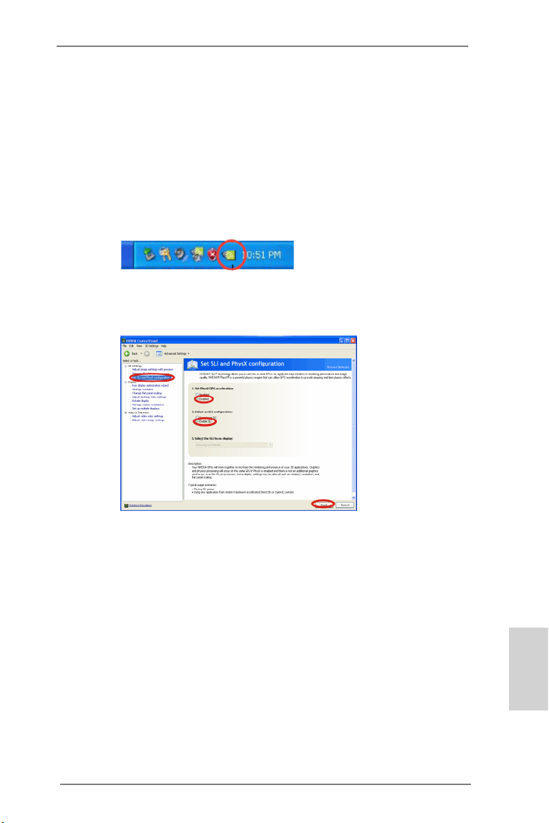
For Windows® XP / XP 64-bit OS:
(For SLITM mode only)
A. Double-click NVIDIA Settings icon on your Windows® taskbar.
B. From the pop-up menu, select Set SLI and PhysX conguration. In
Set PhysX GPU acceleration item, please select Enabled. In Select
an SLI conguration item, please select Enable SLI. And click Apply.
C. Reboot your system.
D. You can freely enjoy the benets of SLITM.
ASRock Z77 Extreme6/TB4 Motherboard
English
23
Page 24
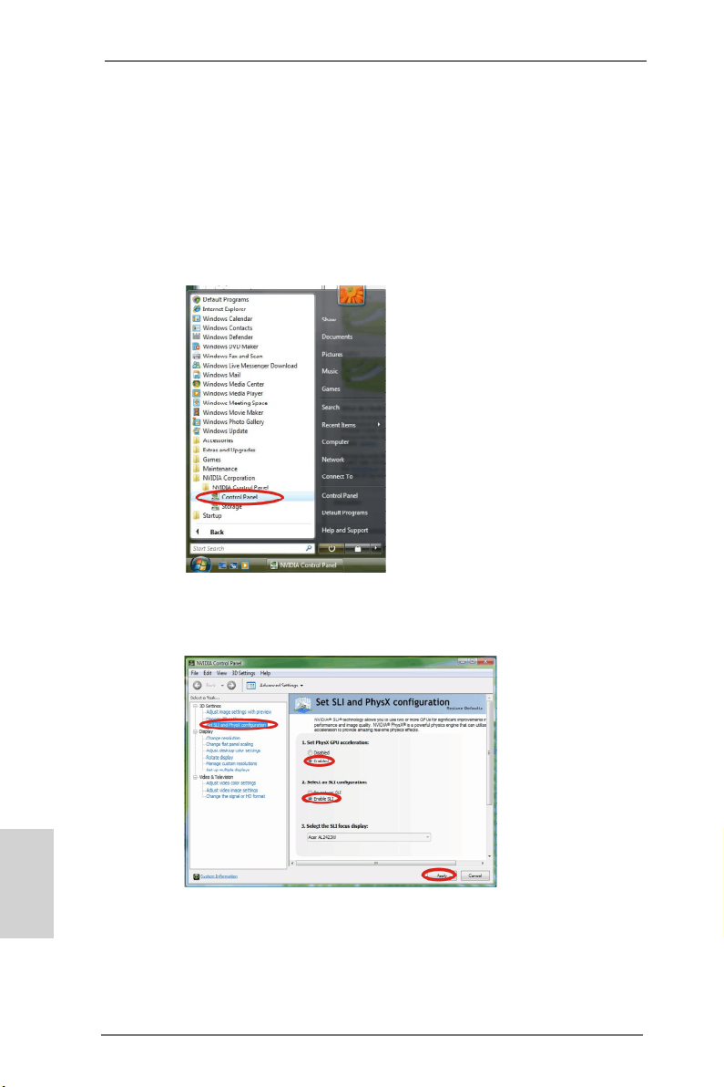
For Windows® VistaTM / VistaTM 64-bit / 7 / 7 64-bit / 8 / 8 64-bit OS:
(For SLITM and Quad SLITM mode)
A. Click the Start icon on your Windows taskbar.
B. From the pop-up menu, select All Programs, and then click NVIDIA
Corporation.
C. Select NVIDIA Control Panel tab.
D. Select Control Panel tab.
E. From the pop-up menu, select Set SLI and PhysX conguration. In
Set PhysX GPU acceleration item, please select Enabled. In Select
an SLI conguration item, please select Enable SLI. And click Apply.
English
24
F. Reboot your system.
G. You can freely enjoy the benets of SLITM or Quad SLITM.
* SLITM appearing here is a registered trademark of NVIDIA® Technologies Inc., and is used
only for identication or explanation and to the owners’ benet, without intent to infringe.
ASRock Z77 Extreme6/TB4 Motherboard
Page 25
2.8 CrossFireXTM and Quad CrossFireXTM Operation Guide
This motherboard supports CrossFireXTM and Quad CrossFireXTM. CrossFireXTM
technology offers the most advantageous means available of combining multiple
high performance Graphics Processing Units (GPU) in a single PC. Combining a
range of different operating modes with intelligent software design and an innovative
interconnect mechanism, CrossFireXTM enables the highest possible level of
performance and image quality in any 3D application. Currently CrossFireXTM is
supported by all Windows® OS. Quad CrossFireXTM is supported by Windows®
VistaTM / 7 / 8 OS only. Please check AMD’s website for AMD CrossFireXTM driver
updates.
1. If a customer incorrectly congures their system they will not see the performance
benets of CrossFireXTM. All three CrossFireXTM components, a CrossFireXTM
Ready graphics card, a CrossFireXTM Ready motherboard and a CrossFireXTM
Edition co-processor graphics card, must be installed correctly to benet from the
CrossFireXTM multi-GPU platform.
2. If you pair a 12-pipe CrossFireXTM Edition card with a 16-pipe card, both cards
will operate as 12-pipe cards while in CrossFireXTM mode.
2.8.1 Installing Two CrossFireXTM-Ready Graphics Cards
Different CrossFireXTM cards may require different methods to enable CrossFireXTM
feature. For other CrossFireXTM cards that AMD has released or will release in the
future, please refer to AMD graphics card manuals for detailed installation guide.
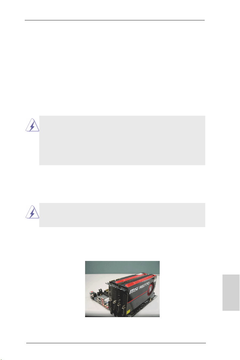
Step 1. Insert one Radeon graphics card into PCIE2 slot and the other Radeon
graphics card to PCIE4 slot. Make sure that the cards are properly seated
on the slots.
ASRock Z77 Extreme6/TB4 Motherboard
English
25
Page 26
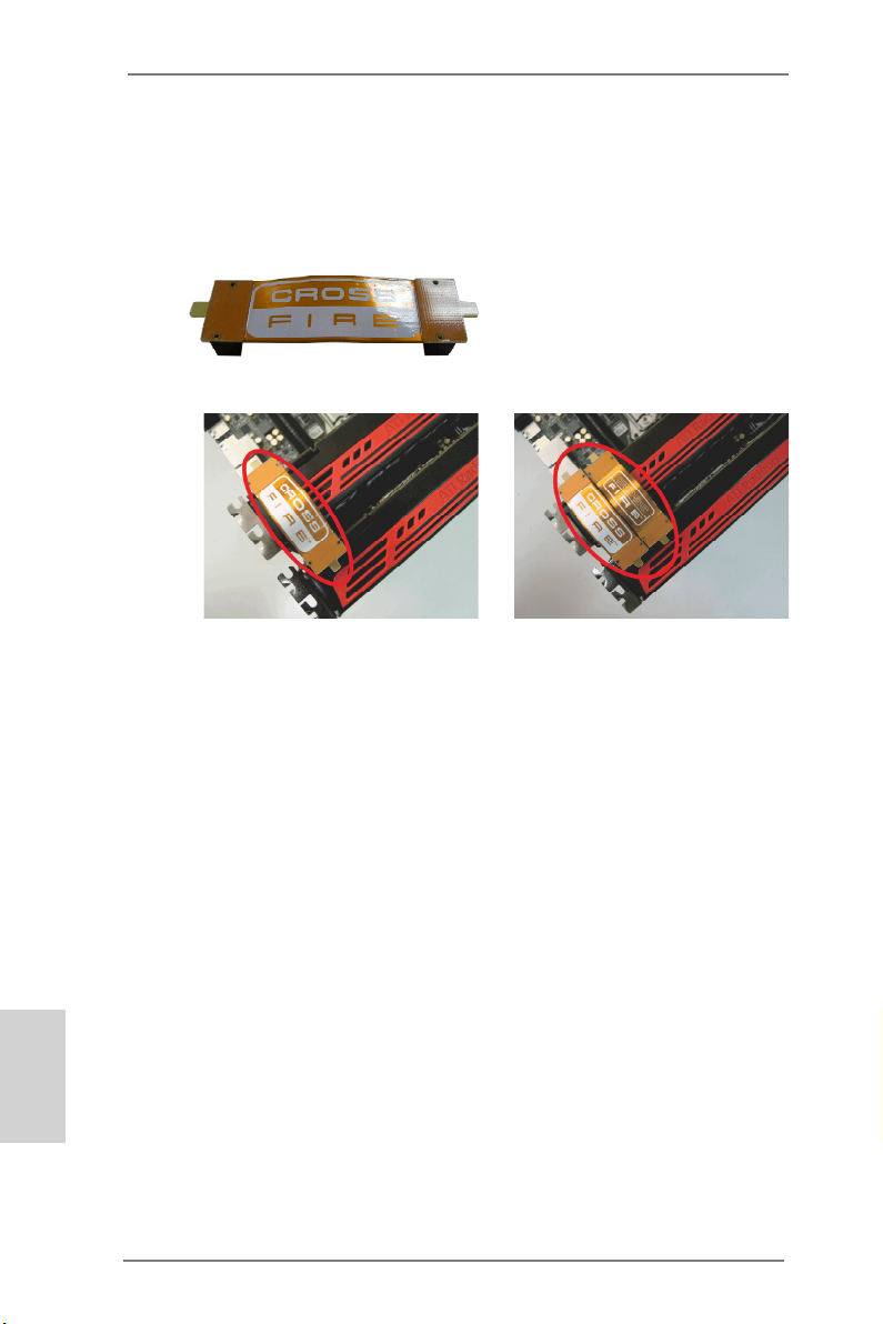
Step 2. Connect two Radeon graphics cards by installing a CrossFire Bridge on
the CrossFire Bridge Interconnects on the top of the Radeon graphics
cards. (The CrossFire Bridge is provided with the graphics card you purchase, not bundled with this motherboard. Please refer to your graphics
card vendor for details.)
CrossFire Bridge
or
Step 3. Connect the DVI monitor cable to the DVI connector on the Radeon graph-
ics card on PCIE2 slot. (You may use the DVI to D-Sub adapter to convert
the DVI connector to D-Sub interface, and then connect the D-Sub monitor
cable to the DVI to D-Sub adapter.)
English
26
ASRock Z77 Extreme6/TB4 Motherboard
Page 27
2.8.2 Driver Installation and Setup
Step 1. Power on your computer and boot into OS.
Step 2. Remove the AMD drivers if you have any VGA drivers installed in your
system.
The Catalyst Uninstaller is an optional download. We recommend using this utility to
uninstall any previously installed Catalyst drivers prior to installation. Please check
AMD’s website for AMD driver updates.
Step 3. Install the required drivers to your system.
For Windows® XP OS:
A. AMD recommends Windows® XP Service Pack 2 or higher to be
installed (If you have Windows® XP Service Pack 2 or higher installed in
your system, there is no need to download it again):
http://www.microsoft.com/windowsxp/sp2/default.mspx
B. You must have Microsoft .NET Framework installed prior to
downloading and installing the CATALYST Control Center. Please check
Microsoft’s website for details.
For Windows® 8 / 7 / VistaTM OS:
Install the CATALYST Control Center. Please check AMD’s website for de-
tails.
Step 4. Restart your computer.
Step 5. Install the VGA card drivers to your system, and restart your computer.
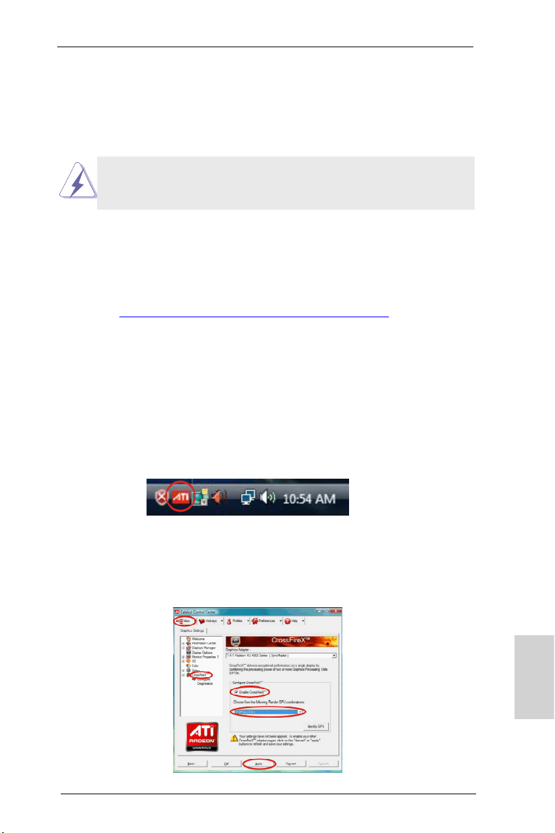
You will nd “AMD Catalyst Control Center” on your Windows® taskbar.
AMD Catalyst Control Center
Step 6. Double-click “AMD Catalyst Control Center”. Click “View”, select “CrossFi-
reXTM”, and then check the item “Enable CrossFireXTM”. Select “2 GPUs”
and click “Apply” (if you install two Radeon graphics cards).
ASRock Z77 Extreme6/TB4 Motherboard
English
27
Page 28
Although you have selected the option “Enable CrossFireTM”, the CrossFireXTM
function may not work actually. Your computer will automatically reboot. After
restarting your computer, please conrm whether the option “Enable CrossFireTM” in
“AMD Catalyst Control Center” is selected or not; if not, please select it again, and
then you are able to enjoy the benets of CrossFireXTM.
Step 7. You can freely enjoy the benets of CrossFireXTM or Quad CrossFireXTM.
* CrossFireXTM appearing here is a registered trademark of AMD Technologies Inc., and is used
only for identication or explanation and to the owners’ benet, without intent to infringe.
* For further information of AMD CrossFireXTM technology, please check AMD’s website for
updates and details.
English
28
ASRock Z77 Extreme6/TB4 Motherboard
Page 29
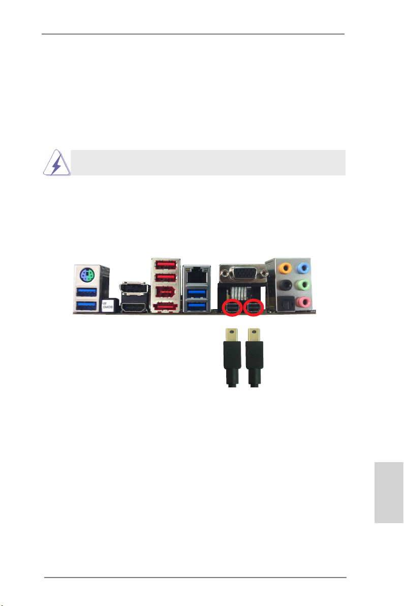
2.9 Thunderbolt
This motherboard has two thunderbolt connectors that support video output from
internal VGA cards. Due to 32-bit OS limitations, we strongly recommend using
a 64-bit OS to bring ThunderBolt into full play. For thunderbolt display installation
please follow the steps below:
Thunderbolt cables are provided by your monitor supplier.
Internal VGA
If you want to use the internal VGA with the Thunderbolt ports, simply connect your
monitor to either Thunderbolt port (see p.3, No. 12,13) on the motherboard using
a Thunderbolt cable.
ASRock Z77 Extreme6/TB4 Motherboard
English
29
Page 30
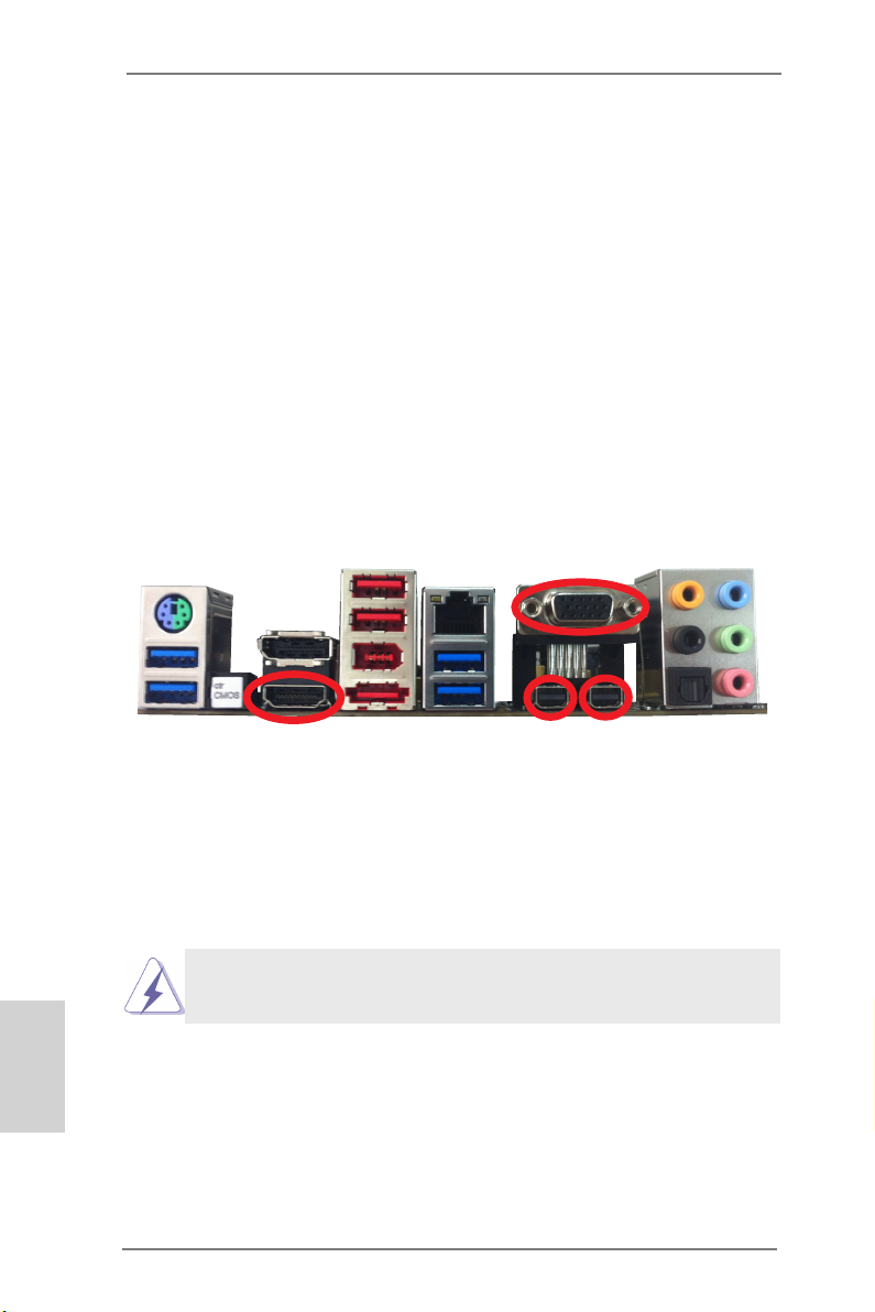
2.10 Dual Monitor and Surround Display
Dual Monitor
This motherboard supports dual monitor. With the internal VGA output support (D-Sub
HDMI and Thunderbolt), you can easily enjoy the benets of dual monitor without installing any add-on VGA cards to this motherboard. This motherboard also provides
independent display controllers for D-Sub, HDMI and Thunderbolt to support dual
VGA output so that the D-Sub, HDMI and Thunderbolt can drive the same or different display contents.
To enable dual monitor, please follow the steps below:
1. Connect a D-Sub monitor cable to the D-Sub port on the I/O panel, connect a
HDMI monitor cable to the HDMI port on the I/O panel, or connect a Thunderbolt
monitor cable to the Thunderbolt ports on the I/O panel.
D-Sub port
English
30
HDMI port
2. If you have already installed the onboard VGA driver from our support CD to your
system, you can freely enjoy the benets of dual monitor function after your
system boots. If you haven’t installed the onboard VGA driver yet, please install
the onboard VGA driver from our support CD to your system and restart your
computer.
D-Sub, HDMI and Thunderbolt monitors cannot be enabled at the same
time. You can only choose two of them.
ASRock Z77 Extreme6/TB4 Motherboard
Thunderbolt ports
Page 31

Surround Display Feature
This motherboard supports surround display upgrade. With the internal VGA output
support (D-Sub HDMI and Thunderbolt) and external add-on PCI Express VGA
cards, you can easily enjoy the benets of surround display.
Please refer to the following steps to set up a surround display environment:
1. Install the PCI Express VGA cards on PCIE2 and PCIE4 slots. Please refer to
page 20 for proper expansion card installation procedures.
2. Connect a D-Sub monitor cable to the D-Sub port on the I/O panel, connect a
HDMI monitor cable to the HDMI port on the I/O panel, or connect a Thunderbolt
monitor cable to the Thunderbolt on the I/O panel. Then connect other monitor
cables to the corresponding connectors of the add-on PCI Express VGA cards on
PCIE2 and PCIE4 slots.
3. Boot your system. Press <F2> or <Del> to enter UEFI setup. Enter “Share
Memory” option to adjust the memory capability to [32MB], [64MB], [128MB],
[256MB] or [512MB] to enable the function of D-sub. Please make sure that the
value you select is less than the total capability of the system memory. If you do
not adjust the UEFI setup, the default value of “Share Memory”, [Auto], will
disable D-Sub function when an add-on VGA card is inserted to this motherboard.
4. Install the onboard VGA driver and the add-on PCI Express VGA card driver to
your system. If you have installed the drivers already, there is no need to install
them again.
5. Set up a multi-monitor display.
For Windows® XP / XP 64-bit OS:
Right click on desktop, choose “Properties”, and select the “Settings” tab
so that you can adjust the parameters of the multi-monitors according to
the steps below.
A. Click the “Identify” button to display a large number on each monitor.
B. Right-click the display icon in the Display Properties dialog that you
wish to be your primary monitor, and then select “Primary”. When
you use multiple monitors with your card, one monitor will always be
Primary, and all additional monitors will be designated as Secondary.
C. Select the display icon identied by the number 2.
D. Click “Extend my Windows desktop onto this monitor”.
E. Right-click the display icon and select “Attached”, if necessary.
F. Set the appropriate “Screen Resolution” and “Color Quality” for the
second monitor. Click “Apply” or “OK” to apply these new values.
G. Repeat steps C through F for the display icons identied by the
numbers.
English
ASRock Z77 Extreme6/TB4 Motherboard
31
Page 32

For Windows® 8 / 8 64-bit / 7 / 7 64-bit / VistaTM / VistaTM 64-bit OS:
Right click the desktop, choose “Personalize”, and select the “Display
Settings” tab so that you can adjust the parameters of the multi-monitors
according to the steps below.
A. Click the number ”2” icon.
B. Click the items “This is my main monitor” and “Extend the desktop onto
this monitor”.
C. Click “OK” to save your change.
D. Repeat steps A through C for the display icons identied by the
numbers.
6. Use Surround Display. Click and drag the display icons to positions representing
the physical setup of your monitors that you would like to use. The placement of
display icons determines how you move items from one monitor to another.
HDCP
HDCP is supported on this motherboard. To use HDCP with this
motherboard, you need to adopt a monitor that supports HDCP
as well. Therefore, you can enjoy the superior display quality
with high-denition HDCP encryption contents. Please refer to
the instructions below for more details about HDCP.
What is HDCP?
HDCP stands for High-Bandwidth Digital Content Protection, a
specication developed by Intel® for protecting digital
entertainment content that uses the DVI interface. HDCP is a
copy protection scheme to eliminate the possibility of
intercepting digital data midstream between the video source,
or transmitter - such as a computer, DVD player or set-top box -
and the digital display, or receiver - such as a monitor, television
or projector. In other words, HDCP specication is designed to
protect the integrity of content as it is being transmitted.
English
32
Products compatible with the HDCP scheme such as DVD
players, satellite and cable HDTV set-top-boxes, as well as few
entertainment PCs requires a secure connection to a compliant
display. Due to the increase in manufacturers employing HDCP
in their equipment, it is highly recommended that the HDTV or
LCD monitor you purchase is compatible.
ASRock Z77 Extreme6/TB4 Motherboard
Page 33

2.11 ASRock Smart Remote Installation Guide
ASRock Smart Remote is only used for ASRock motherboards with a CIR header.
Please refer to the procedures below for the quick installation and usage of ASRock
Smart Remote.
Step1. Find the CIR header located next
to the USB 2.0 header on your
ASRock motherboard.
USB 2.0 header (9-pin, black)
CIR header (4-pin, gray)
Step2. Connect the front USB cable to the
USB 2.0 header (as below, pin 1-5)
and the CIR header. Please make
USB_PWR
P-
P+
GND
DUMMY
sure the wire assignments and the
pin assignments are matched
correctly.
GND
IRTX
IRRX
ATX+5VSB
Step3. Install the Multi-Angle CIR Receiver to the front USB port.
Step4. Boot up your system. Press <F2> or <Del> to enter the BIOS Setup Utility.
Make sure the option "CIR Controller" is set to [Enabled].
(Advanced -> Super IO Conguration -> CIR Controller -> [Enabled])
If you cannot nd this option, please shut down your system and install
the Multi-Angle CIR Receiver to the other front USB port then try again.
Step5. Enter Windows. Execute ASRock's support CD and install the CIR Driver.
(It is listed at the bottom of driver list.)
English
ASRock Z77 Extreme6/TB4 Motherboard
33
Page 34

English
3 CIR sensors in different angles
1. Only one of the front USB ports can support CIR. When CIR is
enabled, the other ports will remain USB ports.
2. The Multi-Angle CIR Receiver is used for the front USB only.
Please do not use the rear USB bracket to connect it on the rear
panel. The Multi-Angle CIR Receiver can receive multi-directional
infrared signals (top, down and front), which is compatible with
most of the chassis on the market.
3. The Multi-Angle CIR Receiver does not support Hot-Plug. Please
install it before you boot the system.
* ASRock Smart Remote is only supported by some ASRock motherboards. Please refer to
ASRock's website for the motherboard support list: http://www.asrock.com
34
ASRock Z77 Extreme6/TB4 Motherboard
Page 35

2.12 Jumpers Setup
The illustration shows how jumpers are
setup. When the jumper cap is placed on
pins, the jumper is “Short”. If no jumper cap
is placed on pins, the jumper is “Open”. The
illustration shows a 3-pin jumper whose
pin1 and pin2 are “Short” when jumper cap
is placed on these 2 pins.
Jumper Setting Description
Clear CMOS Jumper
(CLRCMOS1)
(see p.2, No. 21)
Note: CLRCMOS1 allows you to clear the data in CMOS. To clear and reset the
system parameters to default setup, please turn off the computer and unplug
the power cord from the power supply. After waiting for 15 seconds, use a
jumper cap to short pin2 and pin3 on CLRCMOS1 for 5 seconds. However,
please do not clear the CMOS right after you update the BIOS. If you need
to clear the CMOS when you just nish updating the BIOS, you must boot
up the system rst, and then shut it down before you do the clear-CMOS action. Please be noted that the password, date, time, user default prole, 1394
GUID and MAC address will be cleared only if the CMOS battery is removed.
Clear CMOSDefault
The Clear CMOS Switch has the same function as the Clear CMOS
jumper.
ASRock Z77 Extreme6/TB4 Motherboard
English
35
Page 36

2.13 Onboard Headers and Connectors
Onboard headers and connectors are NOT jumpers. Do NOT place
jumper caps over these headers and connectors. Placing jumper caps
over the headers and connectors will cause permanent damage of the
motherboard!
Serial ATA2 Connectors These four Serial ATA2 (SATA2)
(SATA2_2_3: see p.2, No. 13)
(SATA2_4_5: see p.2, No. 14)
devices. The current SATA2
interface allows up to 3.0 Gb/s
data transfer rate.
Serial ATA3 Connectors These four Serial ATA3 (SATA3)
(SATA3_A1_A2: see p.2, No. 11)
(SATA3_0_1: see p.2, No. 12)
devices. The current SATA3
interface allows up to 6.0 Gb/s
data transfer rate. If the eSATA3
port on the rear I/O has been
connected, the internal
SATA3_A2 will not funtion.
connectors support SATA data
cables for internal storage
SATA2_4 SATA2_2
SATA2_5 SATA2_3
connectors support SATA data
cables for internal storage
SATA3_0 SATA3_A1
SATA3_1 SATA3_A2
English
36
Serial ATA (SATA) Either end of the SATA data
Data Cable cable can be connected to the
(Optional)
SATA / SATA2 / SATA3 hard
disk or the SATA2 / SATA3
connector on this motherboard.
USB 2.0 Headers Besides two default USB 2.0
(9-pin USB2_3)
(see p.2, No. 25)
ports on the I/O panel, there are
three USB 2.0 headers on this
motherboard. Each USB 2.0
header can support two USB 2.0
ports.
ASRock Z77 Extreme6/TB4 Motherboard
Page 37

(9-pin USB4_5)
(see p.2, No. 26)
(9-pin USB6_7)
(see p.2, No. 27)
USB 3.0 Header Besides four default USB 3.0
(19-pin USB3_4_5)
(see p.2, No. 8)
ports on the I/O panel, there is
one USB 3.0 header on this
motherboard. This USB 3.0
header can support two USB 3.0
ports.
Infrared Module Header This header supports an
(5-pin IR1)
optional wireless transmitting
(see p.2, No. 30)
and receiving infrared module.
Consumer Infrared Module Header This header can be used to
(4-pin CIR1)
(see p.2, No. 28)
connect the remote controller
receiver.
Front Panel Audio Header This is an interface for front
(9-pin HD_AUDIO1)
(see p.2, No. 32)
panel audio cable that allows
convenient connection and
control of audio devices.
ASRock Z77 Extreme6/TB4 Motherboard
English
37
Page 38

1. High Denition Audio supports Jack Sensing, but the panel wire on the
chassis must support HDA to function correctly. Please follow the
instruction in our manual and chassis manual to install your system.
2. If you use AC’97 audio panel, please install it to the front panel audio
header as below:
A. Connect Mic_IN (MIC) to MIC2_L.
B. Connect Audio_R (RIN) to OUT2_R and Audio_L (LIN) to OUT2_L.
C. Connect Ground (GND) to Ground (GND).
D. MIC_RET and OUT_RET are for HD audio panel only. You don’t need
to connect them for AC’97 audio panel.
E. To activate the front mic.
For Windows® XP / XP 64-bit OS:
Select “Mixer”. Select “Recorder”. Then click “FrontMic”.
For Windows® 8 / 8 64-bit / 7 / 7 64-bit / VistaTM / VistaTM 64-bit OS:
Go to the “FrontMic” Tab in the Realtek Control panel. Adjust
“Recording Volume”.
System Panel Header This header accommodates
(9-pin PANEL1)
(see p.2, No. 20)
several system front panel
functions.
Connect the power switch, reset switch and system status indicator on the
chassis to this header according to the pin assignments below. Note the
positive and negative pins before connecting the cables.
English
38
PWRBTN (Power Switch):
Connect to the power switch on the chassis front panel. You may congure
the way to turn off your system using the power switch.
RESET (Reset Switch):
Connect to the reset switch on the chassis front panel. Press the reset
switch to restart the computer if the computer freezes and fails to perform a
normal restart.
PLED (System Power LED):
Connect to the power status indicator on the chassis front panel. The LED
is on when the system is operating. The LED keeps blinking when the sys-
tem is in S1/S3 sleep state. The LED is off when the system is in S4 sleep
state or powered off (S5).
HDLED (Hard Drive Activity LED):
Connect to the hard drive activity LED on the chassis front panel. The LED
is on when the hard drive is reading or writing data.
ASRock Z77 Extreme6/TB4 Motherboard
Page 39

The front panel design may differ by chassis. A front panel module mainly
GND
+12V
FAN_SPEED
GND
+12V
FAN_SPEED
FAN_SPEED
FAN_SPEED_CONTROL
+12V
GND
4
2
3
1
consists of power switch, reset switch, power LED, hard drive activity LED,
speaker and etc. When connecting your chassis front panel module to this
header, make sure the wire assignments and the pin assign-ments are
matched correctly.
Chassis Speaker Header Please connect the chassis
(4-pin SPEAKER 1)
(see p.2, No. 22)
speaker to this header.
Power LED Header Please connect the chassis
(3-pin PLED1)
(see p.2, No. 18)
power LED to this header to
indicate system power status.
The LED is on when the system
is operating. The LED keeps
blinking in S1/S3 state. The
LED is off in S4 state or S5
state (power off).
Chassis and Power Fan Connectors Please connect the fan cables
(4-pin CHA_FAN1)
(see p.2, No. 23)
to the fan connectors and match
the black wire to the ground pin.
CHA_FAN1, CHA_FAN2 and
(3-pin CHA_FAN2)
(see p.2, No. 41)
CHA_FAN3 supports Fan
Control.
(3-pin CHA_FAN3)
(see p.2, No. 24)
(3-pin PWR_FAN1)
(see p.2, No. 9)
FAN_SPEED
+12V
GND
CPU Fan Connectors Please connect the CPU fan
(4-pin CPU_FAN1)
(see p.2, No. 3)
cable to the connector and
match the black wire to the
ground pin.
ASRock Z77 Extreme6/TB4 Motherboard
English
39
Page 40

Though this motherboard provides 4-Pin CPU fan (Quiet Fan) support, the 3-Pin
CPU fan still can work successfully even without the fan speed control function.
If you plan to connect the 3-Pin CPU fan to the CPU fan connector on this
motherboard, please connect it to Pin 1-3.
Pin 1-3 Connected
3-Pin Fan Installation
(3-pin CPU_FAN2)
(see p.2, No. 4)
ATX Power Connector Please connect an ATX power
(24-pin ATXPWR1)
(see p.2, No. 7)
supply to this connector.
Though this motherboard provides 24-pin ATX power connector,
FAN_SPEED
+12V
GND
12 124
13
12
24
it can still work if you adopt a traditional 20-pin ATX power supply.
To use the 20-pin ATX power supply, please plug your
power supply along with Pin 1 and Pin 13.
20-Pin ATX Power Supply Installation
ATX 12V Power Connector Please connect an ATX 12V
(8-pin ATX12V1)
(see p.2, No. 1)
power supply to this connector.
8 5
4 1
1
13
Though this motherboard provides 8-pin ATX 12V power connector, it can still work
if you adopt a traditional 4-pin ATX 12V power supply. To use the 4-pin ATX power
supply, please plug your power supply along with Pin 1 and Pin 5.
8 5
English
40
4-Pin ATX 12V Power Supply Installation
ASRock Z77 Extreme6/TB4 Motherboard
4 1
Page 41

SLI/XFIRE Power Connector It is not necessary to use this
(4-pin SLI/XFIRE_PWR1)
(see p.2 No. 40)
connecor when two graphics
cards are plugged to this
connector, but please connect it
with a hard disk power
SLI/XFIRE_POWER1
motherboard.
IEEE 1394 Header Besides one default IEEE 1394
(9-pin FRONT_1394)
(see p.2 No. 19)
port on the I/O panel, there is
one IEEE 1394 header on this
motherboard. This IEEE 1394
header can support one IEEE
1394 port.
Serial port Header This COM1 header supports a
(9-pin COM1)
(see p.2, No. 31)
serial port module.
HDMI_SPDIF Header HDMI_SPDIF header, providing
(2-pin HDMI_SPDIF1)
(see p.2, No. 33)
SPDIF audio output to HDMI
VGA card, allows the system to
connect HDMI Digital TV/
projector/LCD devices. Please
connect the HDMI_SPDIF
connector of HDMI VGA card to
this header.
ASRock Z77 Extreme6/TB4 Motherboard
English
41
Page 42

2.14 Smart Switches
The motherboard has three smart switches: power switch, reset switch and clear
CMOS switch, allowing users to quickly turn on/off or reset the system to clear the
CMOS values.
Power Switch Power Switch is a smart switch,
(PWRBTN)
(see p.2 No. 17)
Reset Switch Reset Switch is a smart switch,
(RSTBTN)
(see p.2 No. 16)
Clear CMOS Switch Clear CMOS Switch is a smart
(CLRCBTN)
(see p.3 No. 18)
allowing users to quickly turn
on/off the system.
allowing users to quickly reset
the system.
switch, allowing users to quickly
clear the CMOS values.
English
42
ASRock Z77 Extreme6/TB4 Motherboard
Page 43

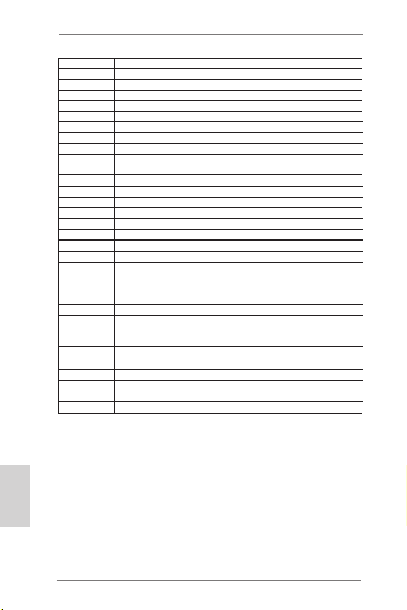
2.15 Dr. Debug
Dr. Debug is used to provide code information, which makes troubleshooting even
easier. Please see the diagrams below for reading the Dr. Debug codes.
Status Code Description
0x00 Not used
0x01 Power on. Reset type detection (soft/hard)
0x02 AP initialization before microcode loading
0x03 North Bridge initialization before microcode loading
0x04 South Bridge initialization before microcode loading
0x05 OEM initialization before microcode loading
0x06 Microcode loading
0x07 AP initialization after microcode loading
0x08 North Bridge initialization after microcode loading
0x09 South Bridge initialization after microcode loading
0x0A OEM initialization after microcode loading
0x0B Cache initialization
0x0C – 0x0D Reserved for future AMI SEC error codes
0x0E Microcode not found
0x0F Microcode not loaded
0x10 PEI Core is started
0x11 Pre-memory CPU initialization is started
0x12 Pre-memory CPU initialization (CPU module specic)
0x13 Pre-memory CPU initialization (CPU module specic)
0x14 Pre-memory CPU initialization (CPU module specic)
0x15 Pre-memory North Bridge initialization is started
0x16 Pre-Memory North Bridge initialization (North Bridge module specic)
0x17 Pre-Memory North Bridge initialization (North Bridge module specic)
0x18 Pre-Memory North Bridge initialization (North Bridge module specic)
0x19 Pre-memory South Bridge initialization is started
0x1A Pre-memory South Bridge initialization (South Bridge module specic)
0x1B Pre-memory South Bridge initialization (South Bridge module specic)
0x1C Pre-memory South Bridge initialization (South Bridge module specic)
0x1D – 0x2A OEM pre-memory initialization codes
0x2B Memory initialization. Serial Presence Detect (SPD) data reading
0x2C Memory initialization. Memory presence detection
0x2D Memory initialization. Programming memory timing information
0x2E Memory initialization. Conguring memory
0x2F Memory initialization (other)
0x30 Reserved for ASL
0x31 Memory Installed
0x32 CPU post-memory initialization is started
0x33 CPU post-memory initialization. Cache initialization
0x34 CPU post-memory initialization. Application Processor(s) (AP) initialization
0x35 CPU post-memory initialization. Boot Strap Processor (BSP) selection
0x36 CPU post-memory initialization. System Management Mode (SMM)
initialization
ASRock Z77 Extreme6/TB4 Motherboard
English
43
Page 44

English
0x37 Post-Memory North Bridge initialization is started
0x38 Post-Memory North Bridge initialization (North Bridge module specic)
0x39 Post-Memory North Bridge initialization (North Bridge module specic)
0x3A Post-Memory North Bridge initialization (North Bridge module specic)
0x3B Post-Memory South Bridge initialization is started
0x3C Post-Memory South Bridge initialization (South Bridge module specic)
0x3D Post-Memory South Bridge initialization (South Bridge module specic)
0x3E Post-Memory South Bridge initialization (South Bridge module specic)
0x3F-0x4E OEM post memory initialization codes
0x4F DXE IPL is started
0x50 Memory initialization error. Invalid memory type or incompatible memory
speed
0x51 Memory initialization error. SPD reading has failed
0x52 Memory initialization error. Invalid memory size or memory modules do not
match
0x53 Memory initialization error. No usable memory detected
0x54 Unspecied memory initialization error
0x55 Memory not installed
0x56 Invalid CPU type or Speed
0x57 CPU mismatch
0x58 CPU self test failed or possible CPU cache error
0x59 CPU micro-code is not found or micro-code update is failed
0x5A Internal CPU error
0x5B reset PPI is not available
0x5C-0x5F Reserved for future AMI error codes
0xE0 S3 Resume is stared (S3 Resume PPI is called by the DXE IPL)
0xE1 S3 Boot Script execution
0xE2 Video repost
0xE3 OS S3 wake vector call
0xE4-0xE7 Reserved for future AMI progress codes
0xE8 S3 Resume Failed
0xE9 S3 Resume PPI not Found
0xEA S3 Resume Boot Script Error
0xEB S3 OS Wake Error
0xEC-0xEF Reserved for future AMI error codes
0xF0 Recovery condition triggered by rmware (Auto recovery)
0xF1 Recovery condition triggered by user (Forced recovery)
0xF2 Recovery process started
0xF3 Recovery rmware image is found
0xF4 Recovery rmware image is loaded
0xF5-0xF7 Reserved for future AMI progress codes
0xF8 Recovery PPI is not available
0xF9 Recovery capsule is not found
0xFA Invalid recovery capsule
0xFB – 0xFF Reserved for future AMI error codes
0x60 DXE Core is started
0x61 NVRAM initialization
44
ASRock Z77 Extreme6/TB4 Motherboard
Page 45

0x62 Installation of the South Bridge Runtime Services
0x63 CPU DXE initialization is started
0x64 CPU DXE initialization (CPU module specic)
0x65 CPU DXE initialization (CPU module specic)
0x66 CPU DXE initialization (CPU module specic)
0x67 CPU DXE initialization (CPU module specic)
0x68 PCI host bridge initialization
0x69 North Bridge DXE initialization is started
0x6A North Bridge DXE SMM initialization is started
0x6B North Bridge DXE initialization (North Bridge module specic)
0x6C North Bridge DXE initialization (North Bridge module specic)
0x6D North Bridge DXE initialization (North Bridge module specic)
0x6E North Bridge DXE initialization (North Bridge module specic)
0x6F North Bridge DXE initialization (North Bridge module specic)
0x70 South Bridge DXE initialization is started
0x71 South Bridge DXE SMM initialization is started
0x72 South Bridge devices initialization
0x73 South Bridge DXE Initialization (South Bridge module specic)
0x74 South Bridge DXE Initialization (South Bridge module specic)
0x75 South Bridge DXE Initialization (South Bridge module specic)
0x76 South Bridge DXE Initialization (South Bridge module specic)
0x77 South Bridge DXE Initialization (South Bridge module specic)
0x78 ACPI module initialization
0x79 CSM initialization
0x7A – 0x7F Reserved for future AMI DXE codes
0x80 – 0x8F OEM DXE initialization codes
0x90 Boot Device Selection (BDS) phase is started
0x91 Driver connecting is started
0x92 PCI Bus initialization is started
0x93 PCI Bus Hot Plug Controller Initialization
0x94 PCI Bus Enumeration
0x95 PCI Bus Request Resources
0x96 PCI Bus Assign Resources
0x97 Console Output devices connect
0x98 Console input devices connect
0x99 Super IO Initialization
0x9A USB initialization is started
0x9B USB Reset
0x9C USB Detect
0x9D USB Enable
0x9E – 0x9F Reserved for future AMI codes
0xA0 IDE initialization is started
0xA1 IDE Reset
0xA2 IDE Detect
0xA3 IDE Enable
0xA4 SCSI initialization is started
0xA5 SCSI Reset
English
ASRock Z77 Extreme6/TB4 Motherboard
45
Page 46
0xA6 SCSI Detect
0xA7 SCSI Enable
0xA8 Setup Verifying Password
0xA9 Start of Setup
0xAA Reserved for ASL
0xAB Setup Input Wait
0xAC Reserved for ASL
0xAD Ready To Boot event
0xAE Legacy Boot event
0xAF Exit Boot Services event
0xB0 Runtime Set Virtual Address MAP Begin
0xB1 Runtime Set Virtual Address MAP End
0xB2 Legacy Option ROM Initialization
0xB3 System Reset
0xB4 USB hot plug
0xB5 PCI bus hot plug
0xB6 Clean-up of NVRAM
0xB7 Conguration Reset (reset of NVRAM settings)
0xB8 – 0xBF Reserved for future AMI codes
0xC0 – 0xCF OEM BDS initialization codes
0xD0 CPU initialization error
0xD1 North Bridge initialization error
0xD2 South Bridge initialization error
0xD3 Some of the Architectural Protocols are not available
0xD4 PCI resource allocation error. Out of Resources
0xD5 No Space for Legacy Option ROM
0xD6 No Console Output Devices are found
0xD7 No Console Input Devices are found
0xD8 Invalid password
0xD9 Error loading Boot Option (LoadImage returned error)
0xDA Boot Option is failed (StartImage returned error)
0xDB Flash update is failed
0xDC Reset protocol is not available
English
46
ASRock Z77 Extreme6/TB4 Motherboard
Page 47

2.16 Driver Installation Guide
To install the drivers to your system, please insert the support CD to your optical
drive rst. Then, the drivers compatible to your system can be auto-detected and
listed on the support CD driver page. Please follow the order from top to bottom to
install those required drivers. Therefore, the drivers you install can work properly.
2.17 Installing Windows® 8 / 8 64-bit / 7 / 7 64-bit / Vista
TM
/ VistaTM
64-bit With RAID Functions
If you want to install Windows® 8 / 8 64-bit / 7 / 7 64-bit / VistaTM / VistaTM 64-bit
on your SATA / SATA2 / SATA3 HDDs with RAID functions, please refer to the
document at the following path in the Support CD for detailed procedures:
..\ RAID Installation Guide
2.18 Installing Windows® 8 / 8 64-bit / 7 / 7 64-bit / Vista
TM
/ VistaTM
64-bit / XP / XP 64-bit Without RAID Functions
If you want to install Windows® 8 / 8 64-bit / 7 / 7 64-bit / VistaTM / VistaTM 64-bit / XP
/ XP 64-bit OS on your SATA / SATA2 / SATA3 HDDs without RAID functions, please
follow the procedures below according to the OS you install.
®
2.18.1 Installing Windows
If you want to install Windows® XP / XP 64-bit OS on your SATA / SATA2 / SATA3
HDDs without RAID functions, please follow the steps below.
Using SATA / SATA2 / SATA3 HDDs without NCQ function
STEP 1: Set Up UEFI.
A. Enter UEFI SETUP UTILITY Advanced screen Storage Conguration.
B. Set the option “SATA Mode Selection” to [IDE]. (For SATA2_2 to SATA2_5,
SATA3_0 and SATA3_1 ports.)
Set the option “ASMedia SATA3 Mode” to [IDE]. (For SATA3_A1 and SATA3_A2
ports.)
STEP 2: Install Windows® XP / XP 64-bit OS on your system.
XP / XP 64-bit Without RAID Functions
English
ASRock Z77 Extreme6/TB4 Motherboard
47
Page 48

2.18.2 Installing Windows® 8 / 8 64-bit / 7 / 7 64-bit / Vista
Vista
If you want to install Windows® 8 / 8 64-bit / 7 / 7 64-bit / VistaTM / VistaTM 64-bit OS
on your SATA / SATA2 / SATA3 HDDs without RAID functions, please follow the
steps below.
Using SATA / SATA2 / SATA3 HDDs with NCQ function
STEP 1: Set Up UEFI.
A. Enter UEFI SETUP UTILITY Advanced screen Storage Conguration.
B. Set the option “SATA Mode Selection” to [AHCI]. (For SATA2_2 to SATA2_5,
SATA3_0 and SATA3_1 ports.)
Set the option “ASMedia SATA3 Mode” to [AHCI]. (For SATA3_A1 and SATA3_A2
ports.)
STEP 2: Install Windows® 8 / 8 64-bit / 7 / 7 64-bit / VistaTM / VistaTM 64-bit OS on
Using SATA / SATA2 / SATA3 HDDs without NCQ function
STEP 1: Set Up UEFI.
A. Enter UEFI SETUP UTILITY Advanced screen Storage Conguration.
B. Set the option “SATA Mode Selection” to [IDE]. (For SATA2_2 to SATA2_5,
SATA3_0 and SATA3_1 ports.)
Set the option “ASMedia SATA3 Mode” to [IDE]. (For SATA3_A1 and SATA3_A2
ports.)
STEP 2: Install Windows® 8 / 8 64-bit / 7 / 7 64-bit / VistaTM / VistaTM 64-bit OS on
TM
64-bit Without RAID Functions
your system.
your system.
TM
/
English
48
ASRock Z77 Extreme6/TB4 Motherboard
Page 49

3. BIOS Information
The Flash Memory on the motherboard stores BIOS Setup Utility. When you start up
the computer, please press <F2> or <Del> during the Power-On-Self-Test (POST)
to enter BIOS Setup utility; otherwise, POST continues with its test routines. If you
wish to enter BIOS Setup after POST, please restart the system by pressing <Ctl>
+ <Alt> + <Delete>, or pressing the reset button on the system chassis. The BIOS
Setup program is designed to be user-friendly. It is a menu-driven program, which
allows you to scroll through its various sub-menus and to select among the predetermined choices. For the detailed information about BIOS Setup, please refer to the
User Manual (PDF le) contained in the Support CD.
4. Software Support CD information
This motherboard supports various Microsoft® Windows® operating systems: 8 /
8 64-bit / 7 / 7 64-bit / VistaTM / Vista
motherboard contains necessary drivers and useful utilities that will enhance motherboard features. To begin using the Support CD, insert the CD into your CD-ROM
drive. It will display the Main Menu automatically if “AUTORUN” is enabled in your
computer. If the Main Menu does not appear automatically, locate and double-click
on the le “ASRSETUP.EXE” in the Support CD to display the menu.
TM
64-bit. The Support CD that came with the
ASRock Z77 Extreme6/TB4 Motherboard
English
49
Page 50

1. Einführung
Wir danken Ihnen für den Kauf des ASRock Z77 Extreme6/TB4 Motherboard, ein
zuverlässiges Produkt, welches unter den ständigen, strengen Qualitätskontrollen von ASRock gefertigt wurde. Es bietet Ihnen exzellente Leistung und robustes
Design, gemäß der Verpflichtung von ASRock zu Qualität und Halbarkeit. Diese
Schnellinstallationsanleitung führt in das Motherboard und die schrittweise Instal-
lation ein. Details über das Motherboard nden Sie in der Bedienungsanleitung auf
der Support-CD.
Da sich Motherboard-Spezikationen und BIOS-Software verändern können,
kann der Inhalt dieses Handbuches ebenfalls jederzeit geändert werden. Für
den Fall, dass sich Änderungen an diesem Handbuch ergeben, wird eine neue
Version auf der ASRock-Website, ohne weitere Ankündigung, verfügbar sein.
Die neuesten Grakkarten und unterstützten CPUs sind auch auf der ASRock-
Website aufgelistet.
ASRock-Website: http://www.asrock.com
Wenn Sie technische Unterstützung zu Ihrem Motherboard oder spezische
Informationen zu Ihrem Modell benötigen, besuchen Sie bitte unsere Webseite:
www.asrock.com/support/index.asp
1.1 Kartoninhalt
ASRock Z77 Extreme6/TB4 Motherboard
(ATX-Formfaktor: 30.5 cm x 24.4 cm; 12.0 Zoll x 9.6 Zoll)
ASRock Z77 Extreme6/TB4 Schnellinstallationsanleitung
ASRock Z77 Extreme6/TB4 Support-CD
Sechs Serial ATA (SATA) -Datenkabel (optional)
Ein I/O Shield
Ein ASRock SLI_Bridge_2S-Karte
Deutsch
50
ASRock Z77 Extreme6/TB4 Motherboard
Page 51

1.2 Spezikationen
Plattform - ATX-Formfaktor: 30.5 cm x 24.4 cm; 12.0 Zoll x 9.6 Zoll
- Hochwertiges Gold-Kondensatordesign (100 % hochwertige
japanische Fertigung leitfähiger Polymerkondensatoren)
CPU - Unterstützt Intel® CoreTM i7- / i5- / i3-Prozessoren der 3ten
und 2ten Generation im LGA1155-Package
- Digi Power-Design
- 8 + 4-Stromphasendesign
- Unterstützt Intel® Turbo Boost 2.0-Technologie
- Unterstützt freigegebene CPU der K-Serie
- Unterstützt Hyper-Threading-Technologie
Chipsatz - Intel® Z77
- Unterstützt Intel® Rapid Start Technology und Smart
Connect Technology
Speicher - Dual-Kanal DDR3 Speichertechnologie
- 4 x Steckplätze für DDR3
- Unterstützt DDR3 2800+(OC)/2400(OC)/2133(OC)/1866
(OC)/1600/1333/1066 non-ECC, ungepufferter Speicher
- Max. Kapazität des Systemspeichers: 32GB
- Unterstützt Intel® Extreme Memory Prole (XMP)1.3/1.2
Erweiterungs- - 2 x PCI Express 3.0 x16-Steckplätze (PCIE2/PCIE4: Einzeln
steckplätze bei x16 (PCIE2) / x8 (PCIE4) oder dual im x8/x8-Modus)
* PCIE 3.0 wird nur mit Intel® Ivy Bridge-Prozessor
unterstützt. Mit Intel® Sandy Bridge-Prozessor wird nur
PCIE 2.0 unterstützt.
- 2 x PCI Express 2.0 x1-Steckplätze
- 2 x PCI -Steckplätze
- Unterstützt AMDTM Quad CrossFireXTM und CrossFireX
- NVIDIA® Quad SLITM und SLI
TM
Onboard-VGA * Integrierte Intel® HD-Grakdarstellungen und die VGA-
Ausgänge können nur durch GPU-integrierte Prozessoren
unterstützt werden.
- Unterstützt hochauösende integrierte Intel®-Graklösungen:
Intel® Quick-Sync-Video 2.0, Intel® InTruTM 3D, Intel® Clear Video-Technik (HD), Intel® InsiderTM und Intel® HD Graphics
2500/4000
- Pixel Shader 5.0, DirectX 11 mit Intel® Ivy Bridge-Prozessor,
Pixel Shader 4.1, DirectX 10.1 mit Intel® Sandy Bridge Prozessor
- Maximal gemeinsam genutzter Speicher 1760MB
TM
Deutsch
ASRock Z77 Extreme6/TB4 Motherboard
51
Page 52

Deutsch
- Drei VGA-Ausgangsoptionen: D-Sub, HDMI sowie
Thunderbolt
- Unterstützt HDMI 1.4a mit einer maximalen Auösung von
1920 x 1200 bei 60 Hz
- Unterstützt D-Sub mit einer maximalen Auösung von 2048
x 1536 bei 75 Hz
- Unterstützt Thunderbolt mit einer maximalen Auösung von
2560 x 1600 bei 60 Hz
- Unterstützt Auto Lip Sync, Deep Color (12bpc), xvYCC und
HBR (High Bit Rate-Audio) mit HDMI
- Unterstützt HDCP mit HDMI
- Unterstutzt 1080p Blu-ray (BD) / HD-DVD-Wiedergabe mit
HDMI
- Unterstützt Datentransferraten bis 10 Gb/s per Thunderbolt
Port
- Unterstützt Daisy-Chain-Verbindungen mit bis zu 6
Thunderbolt-Geräten
Audio - 7.1 CH HD Audio mit dem Inhalt Schutz
(Realtek ALC898 Audio Codec)
- Premium Blu-ray-Audio-Unterstützung
- Unterstützt THX TruStudio
TM
LAN - PCIE x1 Gigabit LAN 10/100/1000 Mb/s
- Broadcom BCM57781
- Unterstützt Wake-On-LAN
- Unterstützt energieefzientes Ethernet 802.3az
- Unterstützt PXE
E/A-Anschlüsse - 1 x PS/2-Mausanschluss/Tastaturanschluss
an der Rückseite - 1 x D-Sub port
- 1 x HDMI port
- 1 x DisplayPort-Eingang für Thunderbolt-Port (TBT2)(Nur
zum Testen)
- 2 x Thunderbolt ports
- 1 x optischer SPDIF-Ausgang
- 2 x Standard-USB 2.0-Anschlüsse
- 1 x eSATA3-Anschluss
- 4 x Standard-USB 3.0-Anschlüsse
- 1 x RJ-45 LAN Port mit LED (ACT/LINK LED und SPEED
LED)
- 1 x IEEE 1394 Port
- 1 x CMOS löschen-Schalter
- HD Audiobuchse: Lautsprecher hinten / Mitte / Bass /
52
ASRock Z77 Extreme6/TB4 Motherboard
Page 53

Audioeingang / Lautsprecher vorne / Mikrofon
SATA3 - 2 x SATA 3-Anschlüsse (6,0 Gb/s) durch Intel® Z77;
unterstützt RAID- (RAID 0, RAID 1, RAID 5, RAID 10, Intel
Rapid Storage und Intel Smart Response-Technologie),
NCQ-, AHCI-und Hot Plug
- 2 x SATA 3-Anschlüsse (6,0 Gb/s) durch ASMedia
ASM1061; unterstützt NCQ-, AHCI-und Hot Plug
(SATA3_A2-Anschluss wird mit dem eSATA-Port geteilt)
USB3.0 - 2 x USB 3.0-Ports an der Rückseite durch Intel® Z77,
unterstützt USB 1.1/2.0/3.0 mit bis zu 5 Gb/s
- 2 x USB 3.0-Ports an der Rückseite durch ASMedia
ASM1042, unterstützt USB 1.1/2.0/3.0 mit bis zu 5 Gb/s
- 1 x USB 3.0-Header (unterstützt zwei USB 3.0-Ports) an der
Vorderseite durch Intel® Z77, unterstützt USB 1.1/2.0/3.0 mit
bis zu 5 Gb/s
Anschlüsse - 4 x SATA2 3,0 GB/s-Anschlüsse, unterstützen RAID- (RAID
0, RAID 1, RAID 5, RAID 10, Intel Rapid Storage und Intel
Smart Response-Technologie), NCQ-, AHCI-und Hot Plug
- 4 x SATA3 6,0 GB/s-Anschlüsse
- 1 x Infrarot-Modul-Header
- 1 x Consumer Infrared-Modul-Header
- 1 x COM-Anschluss-Header
- 1 x HDMI_SPDIF-Anschluss
- 1 x IEEE 1394-Anschluss
- 1 x Betriebs-LED-Header
- 2 x CPUlüfter-Anschlüsse (1 x 4-pin, 1 x 3-pin)
- 3 x Gehäuselüfter-Anschlüsse (1 x 4-pin, 2 x 3-pin)
- 1 x Stromlüfter-Anschluss (3-pin)
- 24-pin ATX-Netz-Header
- 8-pin anschluss für 12V-ATX-Netzteil
- SLI/XFIRE-Netz-Header
- Anschluss für Audio auf der Gehäusevorderseite
- 3 x USB 2.0-Anschlüsse (Unterstützung 6 zusätzlicher USB
2.0-Anschlüsse)
- 1 x USB 3.0-Anschlüsse (Unterstützung 2 zusätzlicher USB
3.0-Anschlüsse)
- 1 x Dr. Debug (Debug-LED mit 7 Segmenten)
- 1 x CMOS löschen-Schalter mit LED
- 1 x Netzschalter mit LED
- 1 x Rücksetzschalter (Reset) mit LED
BIOS - 64Mb AMIs Legal BIOS UEFI mit GUI-Unterstützung
Deutsch
ASRock Z77 Extreme6/TB4 Motherboard
53
Page 54

- Unterstützung für “Plug and Play”
- ACPI 1.1-Weckfunktionen
- JumperFree-Modus
- SMBIOS 2.3.1
- CPU Core, IGPU, DRAM, 1.8V PLL, VTT, VCCSA
Stromspannung Multianpassung
CD d’assistance - Treiber, Dienstprogramme, Antivirussoftware (Probeversion),
CyberLink MediaEspresso 6.5-Testversion, ASRock MAGIX Multimedia-Suite - OEM, Google Chrome-Browser und
Toolbar
Hardware Monitor
- Überwachung der CPU/Gehäuse Temperatur
- Drehzahlmessung für CPU/Gehäuse/Strom lüfter
- Geräuscharmer CPU-/Gehäuselüfter (ermöglicht die
automatische Anpassung der Gehäuselüftergeschwindigkeit
durch CPU-Temperatur)
- Mehrstuge Geschwindigkeitssteuerung für CPU/Gehäuse/
lüfter
- Spannungsüberwachung: +12V, +5V, +3.3V, Vcore
Betriebssysteme - Unterstützt Microsoft® Windows® 8 / 8 64-bit / 7 / 7 64-Bit /
VistaTM / Vista
TM
64-Bit / XP / XP 64-Bit
Zertizierungen - FCC, CE, WHQL
- Gemäß Ökodesign-Richtlinie (ErP/EuP) (Stromversorgung
gemäß Ökodesign-Richtlinie (ErP/EuP) erforderlich)
* Für die ausführliche Produktinformation, besuchen Sie bitte unsere Website:
http://www.asrock.com
Deutsch
54
WARNUNG
Beachten Sie bitte, dass Overclocking, einschließlich der Einstellung im BIOS,
Anwenden der Untied Overclocking-Technologie oder Verwenden von Overclocking Werkzeugen von Dritten, mit einem gewissen Risiko behaftet ist. Overclocking kann
sich nachteilig auf die Stabilität Ihres Systems auswirken oder sogar Komponenten
und Geräte Ihres Systems beschädigen. Es geschieht dann auf eigene Gefahr und
auf Ihre Kosten. Wir übernehmen keine Verantwortung für mögliche Schäden, die
aufgrund von Overclocking verursacht wurden.
ASRock Z77 Extreme6/TB4 Motherboard
Page 55

1.3 Einstellung der Jumper
Die Abbildung verdeutlicht, wie Jumper
gesetzt werden. Werden Pins durch
Jumperkappen verdeckt, ist der Jumper
“Gebrückt”. Werden keine Pins durch
Jumperkappen verdeckt, ist der Jumper
“Offen”. Die Abbildung zeigt einen 3-Pin
Jumper dessen Pin1 und Pin2 “Ge-
brückt” sind, bzw. es bendet sich eine
Jumper-Kappe auf diesen beiden Pins.
Jumper Einstellun Beschreibung
CMOS löschen
(CLRCMOS1, 3-Pin jumper)
(siehe S.2 - No. 21)
Hinweis:
CLRCMOS1 ermöglicht Ihnen die Löschung der Daten im CMOS. Zum
Löschen und Zurücksetzen der Systemparameter auf die Standardeinrichtung
schalten Sie den Computer bitte aus und trennen das Netzkabel von der
Stromversorgung. Warten Sie 15 Sekunden, schließen Sie dann Pin2 und
Pin3 am CLRCMOS1 über einen Jumper fünf Sekunden lang kurz. Sie
sollten das CMOS allerdings nicht direkt nach der BIOS-Aktualisierung
löschen. Wenn Sie das CMOS nach Abschluss der BIOS-Aktualisierung
löschen müssen, fahren Sie zuerst das System hoch. Fahren Sie es dann
vor der CMOS-Löschung herunter. Bitte beachten Sie, dass Kennwort,
Datum, Uhrzeit, benutzerdeniertes Prol, 1394 GUID und MAC-Adresse
nur gelöscht werden, wenn die CMOS-Batterie entfernt wird.
DefaultEinstellung
CMOS
löschen
Der CMOS löschen-Schalter hat dieselbe Funktion wie der CMOS
löschen-Jumper.
ASRock Z77 Extreme6/TB4 Motherboard
Deutsch
55
Page 56

1.4 Integrierte Header und Anschlüsse
Integrierte Header und Anschlüsse sind KEINE Jumper. Setzen Sie KEINE Jumperkappen auf diese Header und Anschlüsse. Wenn Sie Jumperkappen auf Header und Anschlüsse setzen, wird das Motherboard
unreparierbar beschädigt!
Seriell-ATA2-Anschlüsse Diese vier Serial ATA2-
(SATA2_2_3: siehe S.2 - No. 13)
(SATA2_4_5: siehe S.2 - No. 14)
für interne
Massenspeichergeräte. Die
aktuelle SATA2- Schnittstelle
ermöglicht eine
Datenübertragungsrate bis
3,0 Gb/s.
Seriell-ATA3-Anschlüsse Diese vier Serial ATA3-
(SATA3_A1_A2: siehe S.2 - No. 11)
(SATA3_0_1: siehe S.2 - No. 12)
für interne
Massenspeichergeräte. Die
aktuelle SATA3- Schnittstelle
ermöglicht eine
Datenübertragungsrate bis 6,0
Gb/s. Falls der eSATA-Port an
der Rückblende verbunden
wurde, funktioniert der interne
SATA3_A2-Anschluss nicht.
(SATA2-)Verbínder
unterstützten SATA-Datenkabel
SATA2_4 SATA2_2
SATA2_5 SATA2_3
(SATA3-)Verbínder
unterstützten SATA-Datenkabel
SATA3_0 SATA3_A1
SATA3_1 SATA3_A2
Deutsch
56
Serial ATA- (SATA-) SJedes Ende des SATA
Datenkabel Datenkabels kann an die SATA
(Option)
/ SATA2 / SATA3 Festplatte
oder das SATA2 / SATA3
Verbindungsstück auf dieser
Hauptplatine angeschlossen
werden.
ASRock Z77 Extreme6/TB4 Motherboard
Page 57

USB 2.0-Header Zusätzlich zu den zwei üblichen
(9-pol. USB_2_3)
(siehe S.2 - No. 25)
USB 2.0-Ports an den
I/O-Anschlüssen benden sich
drei USB 2.0- Anschlussleisten
am Motherboard. Pro USB 2.0 Anschlussleiste werden zwei
(9-pol. USB_4_5)
(siehe S.2 - No. 26)
(9-pol. USB_6_7)
(siehe S.2 - No. 27)
USB 2.0-Ports unterstützt.
USB 3.0-Header Neben vier Standard-USB
(19-pol. USB3_4_5)
(siehe S.2 - No. 8)
3.0-Ports am E/A-Panel
bendet sich ein USB 3.0-
Header an diesem
Motherboard. Dieser USB 3.0 Header kann zwei USB 3.0 Ports unterstützen.
Infrarot-Modul-Header Dieser Header unterstützt ein
(5-pin IR1)
optionales, drahtloses Sende-
(siehe S.2 - No. 30)
und Empfangs-Infrarotmodul.
Consumer Infrared-Modul-Header Dieser Header kann zum
(4-pin CIR1)
(siehe S.2 - No. 28)
Anschließen Remote-
Empfänger.
ASRock Z77 Extreme6/TB4 Motherboard
Deutsch
57
Page 58

Anschluss für Audio auf Dieses Interface zu einem
der Gehäusevorderseite Audio-Panel auf der Vorder
(9-Pin HD_AUDIO1)
(siehe S.2 - No. 32)
seite Ihres Gehäuses,
ermöglicht Ihnen eine bequeme
Anschlussmöglichkeit und
Kontrolle über Audio-Geräte.
1. High Denition Audio unterstützt Jack Sensing (automatische Erkennung falsch
angeschlossener Geräte), wobei jedoch die Bildschirmverdrahtung am Gehäuse
HDA unterstützen muss, um richtig zu funktionieren. Beachten Sie bei der
Installation im System die Anweisungen in unserem Handbuch und im
Gehäusehandbuch.
2. Wenn Sie die AC’97-Audioleiste verwenden, installieren Sie diese wie
nachstehend beschrieben an der Front-Audioanschlussleiste:
A. Schließen Sie Mic_IN (MIC) an MIC2_L an.
B. Schließen Sie Audio_R (RIN) an OUT2_R und Audio_L (LIN) an OUT2_L an.
C. Schließen Sie Ground (GND) an Ground (GND) an.
D. MIC_RET und OUT_RET sind nur für den HD-Audioanschluss gedacht. Diese
Anschlüsse müssen nicht an die AC’97-Audioleiste angeschlossen werden.
E. So aktivieren Sie das Mikrofon an der Vorderseite.
Bei den Betriebssystemen Windows® XP / XP 64 Bit:
Wählen Sie „Mixer“. Wählen Sie „Recorder“ (Rekorder). Klicken Sie dann auf
„FrontMic“ (Vorderes Mikrofon).
Bei den Betriebssystemen Windows® 8 / 8 64 Bit / 7 / 7 64 Bit / VistaTM / VistaTM
64 Bit:
Wählen Sie im Realtek-Bedienfeld die „FrontMic“ (Vorderes Mikrofon) Registerkarte. Passen Sie die „Recording Volume“ (Aufnahmelautstärke) an.
Deutsch
58
System Panel-Header Dieser Header unterstützt
(9-pin PANEL1)
(siehe S.2 - No. 20)
Schließen Sie die Ein-/Austaste, die Reset-Taste und die
Systemstatusanzeige am Gehäuse an diesen Header an; befolgen Sie
dabei die nachstehenden Hinweise zur Pinbelegung. Beachten Sie die
positiven und negativen Pins, bevor Sie die Kabel anschließen.
PWRBTN (Ein-/Ausschalter):
mehrere Funktion der
Systemvorderseite.
Zum Anschließen des Ein-/Ausschalters an der Frontblende des Gehäu
ses. Sie können kongurieren, wie das System mit Hilfe des
Ein-/Ausschalters ausgeschaltet werden können soll.
ASRock Z77 Extreme6/TB4 Motherboard
Page 59

RESET (Reset-Taste):
Zum Anschließen der Reset-Taste an der Frontblende des Gehäuses.
Mit der Reset-Taste können Sie den Computer im Falle eines Absturzes
neu starten.
PLED (Systembetriebs-LED):
Zum Anschließen der Betriebsstatusanzeige an der Frontblende des
Gehäuses. Die LED leuchtet, wenn das System in Betrieb ist. Die LED
blinkt, wenn sich das System im Ruhezustand S1/S3 bendet. Die LED
schaltet sich aus, wenn sich das System in den Modi S4 bendet
oder ausgeschaltet ist (S5).
HDLED (Festplattenaktivitäts-LED):
Zum Anschließen der Festplattenaktivitäts-LED an der Frontblende des
Gehäuses. Die LED leuchtet, wenn die Festplatte Daten liest oder
schreibt.
Das Design der Frontblende kann je nach Gehäuse variiere. Ein
Frontblendenmodul besteht hauptsächlich aus einer Ein-/Austaste, einer
Reset-Taste, einer Betriebs-LED, einer Festplattenaktivitäts-LED,
Lautsprechern, etc. Stellen Sie beim Anschließen des
Frontblendenmoduls Ihres Gehäuses an diesem Header sicher, dass die
Kabel- und Pinbelegung korrekt übereinstimmen.
Gehäuselautsprecher-Header Schließen Sie den
(4-pin SPEAKER1)
(siehe S.2 - No. 22)
Gehäuselautsprecher an
diesen Header an.
Betriebs-LED-Header Bitte schließen Sie die
(3-pin PLED1)
(siehe S.2 - No. 18)
Betriebs-LED des Gehäuses
zur Anzeige des
Systembetriebsstatus an
diesem Header an. Die LED
leuchtet, wenn das System in
Betrieb ist. Die LED blinkt im
S1/S3-Zustand. Im S4- oder
S5-Zustand (ausgeschaltet)
leuchtet die LED nicht.
ASRock Z77 Extreme6/TB4 Motherboard
Deutsch
59
Page 60

Gehäuse und Strom lüfteranschlüsse Verbinden Sie die Lüfterkabel
GND
+12V
FAN_SPEED
GND
+12V
FAN_SPEED
FAN_SPEED
FAN_SPEED_CONTROL
+12V
GND
4
2
3
1
(4-pin CHA_FAN1)
(siehe S.2, No. 23)
mit den Lüfteranschlüssen,
wobei der schwarze Draht an
den Schutzleiterstift
(3-pin CHA_FAN2)
(siehe S.2 - No. 41)
(3-pin CHA_FAN3)
(siehe S.2 - No. 24)
Lüftersteuerung.
angeschlossenwird.
CHA_FAN1-, CHA_FAN2- und
CHA_FAN3- unterstützen
Deutsch
(3-pin PWR_FAN1)
(siehe S.2 - No. 9)
FAN_SPEED
+12V
GND
CPU-Lüfteranschluss Verbinden Sie das CPU -
(4-pin CPU_FAN1)
(siehe S.2 - No. 3)
Lüfterkabel mit diesem
Anschluss und passen Sie den
schwarzen Draht dem
Erdungsstift an.
Obwohl dieses Motherboard einen vierpoligen CPU-Lüfteranschluss
(Quiet Fan) bietet, können auch CPU-Lüfter mit dreipoligem Anschluss
angeschlossen werden; auch ohne Geschwindigkeitsregulierung. Wenn
Sie einen dreipoligen CPU-Lüfter an den CPU-Lüferanschluss dieses
Motherboards anschließen möchten, verbinden Sie ihn bitte mit den
Pins 1 – 3.
Lüfter mit dreipoligem Anschluss installieren
(3-pin CPU_FAN2)
(sieche S.2 - No. 4)
ATX-Netz-Header Verbinden Sie die ATX
(24-pin ATXPWR1)
(siehe S.2 - No. 7)
Stromversorgung mit diesem
Header.
FAN_SPEED
12 124
+12V
GND
Pins 1–3 anschließen
60
13
ASRock Z77 Extreme6/TB4 Motherboard
Page 61

Obwohl dieses Motherboard einen 24-pol. ATX Stromanschluss bietet, kann es auch mit einem
modizierten traditionellen 20-pol. ATX-Netzteil
verwendet werden. Um ein 20-pol. ATX-Netzteil zu
verwenden, stecken Sie den Stecker mit Pin 1 und
Pin 13 ein.
Installation eines 20-pol. ATX-Netzteils
12
1
24
24
13
13
ATX 12V Anschluss Bitte schließen Sie an diesen
(8-pin ATX12V1)
(siehe S.2 - No. 1)
Anschluss die ATX 12V
Stromversorgung an.
8 5
4 1
Obwohl diese Hauptplatine 8-Pin ATX 12V Stromanschluss zur
Verfügung stellt, kann sie noch arbeiten, wenn Sie einen traditionellen
4-Pin ATX 12V Energieversorgung adoptieren. Um die 4-Pin ATX
Energieversorgung zu verwenden, stecken Sie bitte Ihre
Energieversorgung zusammen mit dem Pin 1 und Pin 5 ein.
8 5
Installation der 4-Pin ATX 12V Energieversorgung
4 1
SLI/XFIRE-Stromanschluss Sie müssen diesen Anschluss
(4-pin SLI/XFIRE_PWR1)
(siehe S.2 - No. 40)
Grakkarten gleichzeitig am
Motherboard angeschlossen
nicht zwingend verwenden.
Wenn allerdings zwei
SLI/XFIRE_POWER1
sind, verbinden Sie diesen
Anschluss bitte mit einem
Festplatten-Stromversorgungs stecker.
ASRock Z77 Extreme6/TB4 Motherboard
Deutsch
61
Page 62

IEEE-1394 Header Außer einem vorgegebenem
(9-pin FRONT_1394)
(siehe S.4 - No. 19)
IEEE-1394 Port auf dem Ein-/
Ausgabe Paneel, gibt es einen
IEEE-1394 Header
(FRONT_1394) auf dieser
Hauptplatine. Dieser IEEE-1394
Header kann einen IEEE-1394
Port unterstützen.
COM-Anschluss-Header Dieser COM-Anschluss- Header
(9-pin COM1)
(siehe S.2 - No. 31)
wird verwendet, um ein
COM-Anschlussmodul zu
unterstützen.
HDMI_SPDIF-Anschluss Der HDMI_SPDIF-Anschluss
(2-pin HDMI_SPDIF1)
(siehe S.2 - No. 33)
stellt einen SPDIF-
Audioausgang für eine HDMI VGA-Karte zur Verfügung und
ermöglicht den Anschluss von
HDMI-Digitalgeräten wie
Fernsehgeräten, Projektoren,
LCD-Geräten an das System.
Bitte verbinden Sie den
HDMI_SPDIF-Anschluss der
HDMI-VGA-Karte mit diesem
Anschluss.
Deutsch
62
ASRock Z77 Extreme6/TB4 Motherboard
Page 63

1.5 Schnellschalter
Dieses Motherboard besitzt drei Schnellschalter: Netzschalter, Rücksetzschalter
(Reset) und CMOS löschen-Schalter, mit denen Benutzer das System schnell ein-/
ausschalten oder zurücksetzen oder die CMOS-Werte löschen können.
Netzschalter Der Netzschalter ist ein
(PWRBTN)
(siehe S.2 - No. 17)
ein-/ausschalten können.
Rücksetzschalter (Reset) Der Rücksetzschalter (Reset)
(RSTBTN)
(siehe S.2 - No. 16)
zurücksetzen können.
CMOS löschen-Schalter Der CMOS löschen-Schalter ist
(CLRCBTN)
(siehe S.3 - No. 18)
schnell löschen können.
Schnellschalter, mit dem
Benutzer das System schnell
ist ein Schnellschalter, mit dem
Benutzer das System schnell
ein Schnellschalter, mit dem
Benutzer die CMOS-Werte
ASRock Z77 Extreme6/TB4 Motherboard
Deutsch
63
Page 64

2. BIOS-Information
Das Flash Memory dieses Motherboards speichert das Setup-Utility. Drücken Sie
<F2> oder <Del> während des POST (Power-On-Self-Test) um ins Setup zu gelangen, ansonsten werden die Testroutinen weiter abgearbeitet. Wenn Sie ins Setup
gelangen wollen, nachdem der POST durchgeführt wurde, müssen Sie das System
über die Tastenkombination <Ctrl> + <Alt> + <Delete> oder den Reset-Knopf auf
der Gehäusevorderseite, neu starten. Natürlich können Sie einen Neustart auch
durchführen, indem Sie das System kurz ab- und danach wieder anschalten.
Das Setup-Programm ist für eine bequeme Bedienung entwickelt worden. Es ist
ein menügesteuertes Programm, in dem Sie durch unterschiedliche Untermenüs
scrollen und die vorab festgelegten Optionen auswählen können. Für detaillierte
Informationen zum BIOS-Setup, siehe bitte das Benutzerhandbuch (PDF Datei) auf
der Support CD.
3. Software Support CD information
Dieses Motherboard unterstützt eine Reiche von Microsoft® Windows® Betriebssystemen: 8 / 8 64-Bit / 7 / 7 64-Bit / VistaTM / VistaTM 64-Bit. Die Ihrem Motherboard
beigefügte Support-CD enthält hilfreiche Software, Treiber und Hilfsprogramme, mit
denen Sie die Funktionen Ihres Motherboards verbessern können Legen Sie die
Support-CD zunächst in Ihr CD-ROM-Laufwerk ein. Der Willkommensbildschirm
mit den Installationsmenüs der CD wird automatisch aufgerufen, wenn Sie die
“Autorun”-Funktion Ihres Systems aktiviert haben.
Erscheint der Wilkommensbildschirm nicht, so “doppelklicken” Sie bitte auf das File
ASRSETUP.EXE im der Support-CD, um die Menüs aufzurufen.
Das Setup-Programm soll es Ihnen so leicht wie möglich machen. Es ist menügesteuert, d.h. Sie können in den verschiedenen Untermenüs Ihre Auswahl treffen und
die Programme werden dann automatisch installiert.
Deutsch
64
ASRock Z77 Extreme6/TB4 Motherboard
Page 65

1. Introduction
Merci pour votre achat d’une carte mère ASRock Z77 Extreme6/TB4, une carte
mère très able produite selon les critères de qualité rigoureux de ASRock. Elle
offre des performances excellentes et une conception robuste conformément à
l’engagement d’ASRock sur la qualité et la abilité au long terme.
Ce Guide d’installation rapide présente la carte mère et constitue un guide
d’installation pas à pas. Des informations plus détaillées concernant la carte
mère pourront être trouvées dans le manuel l’utilisateur qui se trouve sur le CD
d’assistance.
Les spécications de la carte mère et le BIOS ayant pu être mis à jour, le
contenu de ce manuel est sujet à des changements sans notication. Au
cas où n’importe qu’elle modication intervenait sur ce manuel, la version
mise à jour serait disponible sur le site web ASRock sans nouvel avis.
Vous trouverez les listes de prise en charge des cartes VGA et CPU
également sur le site Web ASRock.
Site web ASRock, http://www.asrock.com
Si vous avez besoin de support technique en relation avec cette carte
mère, veuillez consulter notre site Web pour de plus amples informations
particulières au modèle que vous utilisez.
www.asrock.com/support/index.asp
1.1 Contenu du paquet
Carte mère ASRock Z77 Extreme6/TB4
(Facteur de forme ATX: 12.0 pouces x 9.6 pouces, 30.5 cm x 24.4 cm)
Guide d’installation rapide ASRock Z77 Extreme6/TB4
CD de soutien ASRock Z77 Extreme6/TB4
Six câbles de données de série ATA (SATA) (en option)
Un I/O Panel Shield
Un carte 2S_Pont_ASRock SLI
ASRock Z77 Extreme6/TB4 Motherboard
Français
65
Page 66

Français
1.2 Spécications
Format - Facteur de forme ATX: 12.0 pouces x 9.6 pouces, 30.5
cm x 24.4 cm
- Design de condensateur Premium Gold (condensateurs
polymère conducteur de qualité supérieure 100% fabriqués
au Japon)
CPU - Prend en charge les processeurs Intel® CoreTM i7 / i5 / i3
2ème et 3ème génération sur socket LGA1155
- Conception Digi Power
- 8 + 4 Power Phase conception
- Prend en charge la technologie Intel® Turbo Boost 2.0
- Prise en charge des unités centrales non verrouillées de
série K
- Prise en charge de la technologie Hyper-Threading
Chipsets - Intel® Z77
- Prend en charge les technologies Intel® Rapid Start et Smart
Connect
Mémoire - Compatible avec la Technologie de Mémoire à Canal
Double
- 4 x slots DIMM DDR3
- Supporter DDR3 2800+(OC)/2400(OC)/2133(OC)/1866(OC)
/1600/1333/1066 non-ECC, sans amortissement mémoire
- Capacité maxi de mémoire système: 32GB
- Prend en charge le prol de mémoire extrême Intel® (XMP)
1.3/1.2
Slot d’extension - 2 x slots PCI Express 3.0 x16 (PCIE2/PCIE4 : simple à x16
(PCIE2) / x8 (PCIE4) ou double en mode x8/x8)
* PCIE 3.0 n’est pris en charge qu’avec le processeur Intel®
Ivy Bridge. Avec le processeur Intel® Sandy Bridge, seul
PCIE 2.0 est pris en charge.
- 2 x slot PCI Express 2.0 x1
- 2 x slots PCI
- Prend en charge AMD Quad CrossFireXTM et CrossFireX
- Prend en charge NVIDIA® Quad SLITM et SLI
TM
VGA sur carte * Intel® HD Graphics avec visuels intégrés (Built-in Visuals) et
les sorties VGA sont uniquement pris en charge par les
processeurs à GPU intégré.
- Supporte Intel® HD Graphics Built-in Visuals: Intel® Quick
Sync Video 2.0, Intel® InTruTM 3D, Intel® Clear Video HD
Technology, Intel® InsiderTM et Intel® HD Graphics 2500/4000
TM
66
ASRock Z77 Extreme6/TB4 Motherboard
Page 67

- Pixel Shader 5.0, DirectX 11 avec CPU Intel® Ivy Bridge,
Pixel Shader 4.1, DirectX 10.1 avec CPU Intel® Sandy
Bridge
- Mémoire partagée max 1760MB
- Trois options de sortie VGA: D-Sub, HDMI et Thunderbolt
- Prend en charge le HDMI 1.4a avec une résolution
maximale jusqu’à 1920x1200 @ 60Hz
- Prend en charge le D-Sub avec une résolution maximale
jusqu’à 2048x1536 @ 75Hz
- Prend en charge le Thunderbolt avec une résolution
maximale jusqu’à 2560x1600 @ 60Hz
- Prend en charge Lip Sync, Deep Color (12bpc), xvYCC et
HBR (Audio à haut débit binaire) avec HDMI
- Prise en charge HDCP par HDMI
- Supporter 1080p Blu-ray(BD)/ lecteur de HD-DVD avec
HDMI
- Prend en charge le transfert de données jusqu’à 10Gbps via
port Thunderbolt
- Prend en charge jusqu’à 6 appareils Thunderbolt via
connexion en guirlande
Audio - 7,1 CH HD Audio avec protection de contenu
(Realtek ALC898 Audio Codec)
- Prise en charge de l’audio Premium Blu-ray
- Prend en charge THX TruStudio
TM
LAN - PCIE x1 Gigabit LAN 10/100/1000 Mb/s
- Broadcom BCM57781
- Support du Wake-On-LAN
- Prend en charge la norme Energy Efcient Ethernet
(Ethernet à efcacité énergétique) 802.3az
- Supporte PXE
Panneau arrière - 1 x port souris/clavier PS/2
- 1 x port D-Sub
- 1 x port HDMI
- 1 x Entrée DisplayPort pour port Thunderbolt (TBT2)(Pour le
test)
- 2 x ports Thunderbolt
- 1 x Port de sortie optique SPDIF
- 2 x ports USB 2.0 par défaut
- 1 x Connecteur eSATA3
- 4 x ports USB 3.0 par défaut
- 1 x port LAN RJ-45 avec LED (ACT/LED CLIGNOTANTE et
Français
ASRock Z77 Extreme6/TB4 Motherboard
67
Page 68

Français
LED VITESSE)
- 1 x port IEEE 1394
- 1 x interrupteur d’effacement du CMOS
- Prise HD Audio: Haut-parleur arrière / Central /Basses /
Entrée Ligne / Haut-parleur frontal / Microphone
SATA 3 - 2 x connecteurs SATA3 6,0 Gb/s par Intel® Z77, prennent en
charge RAID (RAID 0, RAID 1, RAID 5, RAID 10, Intel Rapid
Storage et Intel Smart Response), NCQ, AHCI et Hot Plug
- 2 x connecteurs SATA3 6,0 Gb/s par ASMedia ASM1061,
prennent en charge NCQ, AHCI et Hot Plug (le connecteur
SATA3_A2 est partagé avec le port eSATA)
USB 3.0 - 2 x ports USB3.0 à l’arrière par Intel® Z77, prennent en
charge USB 1.1/2.0/3.0 jusqu’à 5Gb/s
- 2 x ports USB3.0 à l’arrière par ASMedia ASM1042,
prennent en charge USB 1.1/2.0/3.0 jusqu’à 5Gb/s
- 1 x barrette USB3.0 en façade (prend en charge 2 ports
USB 3.0) par Intel® Z77, prend en charge USB 1.1/2.0/3.0
jusqu’à 5Gb/s
Connecteurs - 4 x connecteurs SATA2 3,0 Gb/s, prennent en charge RAID
(RAID 0, RAID 1, RAID 5, RAID 10, Intel Rapid Storage et
Intel Smart Response), NCQ, AHCI et Hot Plug
- 4 x connecteurs SATA3 6,0 Gb/s
- 1 x En-tête du module infrarouge
- 1 x Barrette pour module à infrarouges grand public
- 1 x En-tête de port COM
- 1 x Connecteur HDMI_SPDIF
- 1 x connecteur IEEE 1394
- 1 x Connecteur de LED d’alimentation
- 2 x Connecteurs pour ventilateur de CPU (1 x br. 4, 1 x br. 3)
- 3 x Connecteurs pour ventilateur de Châssis (1 x br. 4, 2 x
br. 3)
- 1 x Connecteur pour ventilateur de pouvoir (br. 3)
- br. 24 connecteur d’alimentation ATX
- br. 8 connecteur d’alimentation 12V ATX
- Connecteur d’alimentation SLI/XFIRE
- Connecteur audio panneau avant
- 3 x En-tête USB 2.0 (prendre en charge 6 ports USB 2.0
supplémentaires)
- 1 x En-tête USB 3.0 (prendre en charge 2 ports USB 3.0
supplémentaires)
- 1 x Dr. Debug (LED de débogage à 7 segments)
68
ASRock Z77 Extreme6/TB4 Motherboard
Page 69

- 1 x interrupteur d’effacement du CMOS avec LED
- 1 x interrupteur d’alimentation avec LED
- 1 x interrupteur de réinitialisation avec LED
BIOS - 64Mb AMI UEFI Legal BIOS avec support GUI
- Support du “Plug and Play”
- Compatible pour événements de réveil ACPI 1.1
- Gestion jumperless
- Support SMBIOS 2.3.1
- CPU Core, IGPU, DRAM, 1.8V PLL, VTT, VCCSA Tension
Multi-ajustement
CD d’assistance - Pilotes, utilitaires, logiciel anti-virus (version d’évaluation),
CyberLink MediaEspresso 6.5 Trial, Suite multimédia
ASRock MAGIX - OEM, Navigateur et barre d’outils Google
Chrome
Surveillance - Détection de la température de l’UC/châssis
système - Tachéomètre ventilateur processeur/châssis/pouvoir
ventilateur
- Ventilateur silencieux pour unité centrale/châssis (permet le
réglage automatique de la vitesse du ventilateur pour
châssis, selon la température de l’unité centrale)
- Commande de ventilateur CPU/Châssis à plusieurs
vitesses
- Monitoring de la tension: +12V, +5V, +3.3V, Vcore
OS - Microsoft® Windows® 8 / 8 64-bit / 7 / 7 64-bit / VistaTM /
Vista
TM
64-bit / XP / XP 64-bit
Certications - FCC, CE, WHQL
- Prêt pour ErP/EuP (alimentation Prêt pour ErP/EuP requise)
* Pour de plus amples informations sur les produits, s’il vous plaît visitez notre site web:
http://www.asrock.com
ATTENTION
Il est important que vous réalisiez qu’il y a un certain risque à effectuer
l’overclocking, y compris ajuster les réglages du BIOS, appliquer la technologie
Untied Overclocking, ou utiliser des outils de tiers pour l’overclocking. L’overclocking
peut affecter la stabilité de votre système, ou même causer des dommages aux
composants et dispositifs de votre système. Si vous le faites, c’est à vos frais et
vos propres risques. Nous ne sommes pas responsables des dommages possibles
causés par l’overclocking.
ASRock Z77 Extreme6/TB4 Motherboard
Français
69
Page 70

1.3 Réglage des cavaliers
L’illustration explique le réglage des cavaliers. Quand un capuchon est placé sur les
broches, le cavalier est « FERME ». Si aucun capuchon ne relie les broches,le cavalier est « OUVERT ». L’illustration montre un
cavalier à 3 broches dont les broches 1 et 2
sont « FERMEES » quand le capuchon est
placé sur ces 2 broches.
Le cavalier Description
Effacer la CMOS
(CLRCMOS1)
(voir p.2 g. 21)
Remarque :
Paramètres
par défaut
CLRCMOS1 vous permet d’effacer les données du CMOS. Pour effacer
et réinitialiser les paramètres du système à la conguration originale,
veuillez éteindre l’ordinateur et débrancher le cordon d’alimentation de
la prise de courant. Après 15 secondes, utilisez un couvercle de jumper
pour court-circuiter les broches pin2 et pin3 de CLRCMOS1 pendant
secondes. Veuillez cependant ne pas effacer le CMOS immédiatement
a
près avoir mis à jour le BIOS. Si vous avez besoin d’effacer le CMOS
après avoir mis à jour le BIOS, vous devez allumer en premier le
système, puis l’éteindre avant de continuer avec l’opération d’effacement
du CMOS. Veuillez noter que le mot de passe, la date, l’heure, le prol
par défaut de l’utilisateur, 1394 GUID et l’adresse MAC seront effacés
seulement si la batterie du CMOS est enlevée.
Effacer la
CMOS
5
Français
70
Le commutateur Effacer CMOS présente la même fonction que le
cavalier Effacer CMOS.
ASRock Z77 Extreme6/TB4 Motherboard
Page 71

1.4 En-têtes et Connecteurs sur Carte
Les en-têtes et connecteurs sur carte NE SONT PAS des cavaliers.
NE PAS placer les capuchons de cavalier sur ces en-têtes et connecteurs. Le fait de placer les capuchons de cavalier sur les en-têtes
et connecteurs causera à la carte mère des dommages irréversibles!
Connecteurs Série ATA2 Ces quatre connecteurs Série
(SATA2_2_3: voir p.2 No. 13)
(SATA2_4_5: voir p.2 No. 14)
les périphériques de stockage
internes. L’interface SATA2
actuelle permet des taux
transferts de données pouvant
aller jusqu’à 3,0 Gb/s.
Connecteurs Série ATA3 Ces quatre connecteurs Série
(SATA3_A0_A1: voir p.2 No. 11)
(SATA3_0_1: voir p.2 No. 12)
les périphériques de stockage
internes. L’interface SATA3
actuelle permet des taux
transferts de données pouvant
aller jusqu’à 6,0 Gb/s. Si le port
eSATA sur le panneau E/S
arrière est utilisé, le SATA3_A2
interne ne fonctionnera pas.
ATA2 (SATA2) prennent en
charge les câbles SATA pour
SATA2_4 SATA2_2
SATA2_5 SATA2_3
ATA3 (SATA3) prennent en
charge les câbles SATA pour
SATA3_0 SATA3_A1
SATA3_1 SATA3_A2
Câble de données Toute cote du ca bl e de data
Série ATA (SATA) SATA peut etre connecte au
(en option)
disque dur SATA / SATA2 /
SATA3 ou au connecteur SATA2
/ SATA3 sur la carte mere.
ASRock Z77 Extreme6/TB4 Motherboard
Français
71
Page 72

En-tête USB 2.0 A côté des deux ports USB 2.0
(USB_2_3 br. 9)
(voir p.2 No. 25)
par défaut sur le panneau E/S,
il y a trois embases USB 2.0
sur cette carte mère. Chaque
embase USB 2.0 peut prendre
en charge 2 ports USB 2.0.
(USB_4_5 br. 9)
(voir p.2 No. 26)
(USB_6_7 br. 9)
(voir p.2 No. 27)
En-tête USB 3.0 En plus des quatre ports USB
(USB3_4_5 br. 19)
(voir p.2 No. 8)
3.0 par défaut sur le panneau
E/S, il y a une barrette USB 3.0
sur la carte mère. Cette barrette
USB 3.0 peut prendre en
charge deux ports USB 3.0.
Français
72
En-tête du module infrarouge Cet en-tête supporte un module
(IR1 br. 5)
infrarouge optionnel de transfert
(voir p.2 No. 30)
et de réception sans l.
Barrette pour module à infrarouges grand public Cette barrette peut être utilisée
(CIR1 br.4)
pour connecter des récepteur.
(voir p.2 No. 28)
ASRock Z77 Extreme6/TB4 Motherboard
Page 73

Connecteur audio panneau C’est une interface pour un
(HD_AUDIO1 br. 9)
(voir p.2 No. 32)
câble avant audio en façade qui
permet le branchement et le
contrôle commodes de
périphériques audio.
1. L’audio à haute dénition (HDA) prend en charge la détection de che, mais le l
de panneau sur le châssis doit prendre en charge le HDA pour fonctionner
correctement. Veuillez suivre les instructions dans notre manuel et le manuel de
châssis an installer votre système.
2. Si vous utilisez le panneau audio AC’97, installez-le sur l’adaptateur audio
du panneau avant conformément à la procédure ci-dessous:
A. Connectez Mic_IN (MIC) à MIC2_L.
B. Connectez Audio_R (RIN) à OUT2_R et Audio_L (LIN) à OUT2_L.
C. Connectez Ground (GND) à Ground (GND).
D. MIC_RET et OUT_RET sont réservés au panneau audio HD. Vous
n’avez pas besoin de les connecter pour le panneau audio AC’97.
E. Pour activer le micro avant.
Pour les systèmes d’exploitation Windows® XP / XP 64 bits :
Sélectionnez “Mixer”. Sélectionnez “Recorder” (Enregistreur). Puis
cliquez sur “FrontMic” (Micro avant).
Pour les systèmes d’exploitation Windows® 8 / 8 64 bits / 7 / 7 64
bits / VistaTM / VistaTM 64 bits :
Allez sur l’onglet “FrontMic” (Micro avant) sur le Panneau de
contrôle Realtek. Ajustez “Recording Volume” (Volume
d’enregistrement).
En-tête du panneau système Cet en-tête permet d’utiliser
(PANEL1 br. 9)
(voir p.2 No. 20)
Connectez l’interrupteur d’alimentation, l’interrupteur de réinitialisation et
l’indicateur d’état du système du châssis sur cette barrette en respectant
l’affectation des broches décrite ci-dessous. Faites attention aux broches
positives et négatives avant de connecter les câbles.
plusieurs fonctions du panneau
système frontal.
ASRock Z77 Extreme6/TB4 Motherboard
Français
73
Page 74

PWRBTN (Interrupteur d’alimentation):
Connectez ici le connecteur d’alimentation sur le panneau avant du
châssis. Vous pouvez congurer la façon de mettre votre système hors
tension avec l’interrupteur d’alimentation.
RESET (Interrupteur de réinitialisation):
Connectez ici le connecteur de réinitialisation sur le panneau avant du
châssis. Appuyez sur l’interrupteur de réinitialisation pour redémarrer
l’ordinateur s’il se bloque ou s’il n’arrive pas à redémarrer normalement.
PLED (DEL alimentation système):
Connectez ici l’indicateur d’état de l’alimentation sur le panneau avant du
châssis. Ce voyant DEL est allumé lorsque le système est en marche.
Le voyant DEL clignote lorsque le système est en mode veille S1/S3. Le
voyant DEL est éteint lorsque le système est en mode veille S4 ou
lorsqu’il est éteint (S5).
HDLED (DEL activité du disque dur):
Connectez ici le voyant DEL d’activité du disque dur sur le panneau
avant du châssis. Ce voyant DEL est allumé lorsque le disque dur est en
train de lire ou d’écrire des données.
Le design du panneau avant peut varier en fonction du châssis. Un
module de panneau avant consiste principalement en : interrupteur
d’alimentation, interrupteur de réinitialisation, voyant DEL d’alimentation,
voyant DEL d’activité du disque dur, haut-parleur, etc. Lorsque vous
connectez le panneau avant de votre châssis sur cette barrette, vériez
bien à faire correspondre les ls et les broches.
Français
74
En-tête du haut-parleur Veuillez connecter le
de châssis haut-parleur de châssis sur cet
(SPEAKER1 br. 4)
(voir p.2 No. 22)
en-tête.
LED di accensione Collegare il LED di accensione
(PLED1 br. 3)
(voir p.2 Nr. 18)
chassi per indicare lo stato di
alimentazione del sistema. Il
LED è acceso quando il sistema
è in funzione. Il LED continua a
lampeggiare in stato S1/S3. Il
LED è spento in stato S4 o S5
(spegnimento).
ASRock Z77 Extreme6/TB4 Motherboard
Page 75

Connecteur pour châssis et ventilateur Branchez les câbles du
GND
+12V
FAN_SPEED
GND
+12V
FAN_SPEED
FAN_SPEED
FAN_SPEED_CONTROL
+12V
GND
4
2
3
1
(CHA_FAN1 br. 4)
(voir p.2 No. 23)
ventilateur aux connecteurs
pour ventilateur et faites
correspondre le l noir à la
(CHA_FAN2 br. 3)
(voir p.2 No. 41)
CHA_FAN2 et CHA_FAN3
broche de terre. CHA_FAN1,
prennent en charge la fonction
(CHA_FAN3 br. 3)
(voir p.2 No. 24)
contrôle du ventilateur.
(PWR_FAN1 br. 3)
(voir p.2 No. 9)
FAN_SPEED
+12V
GND
Connecteur du ventilateur Veuillez connecter le câble de
de l’UC ventilateur d’UC sur ce
(CPU_FAN1 br. 4)
(voir p.2 No. 3)
Bien que cette carte mère offre un support de (Ventilateur silencieux
ventilateur de CPU à 4 broches , le ventilateur de CPU à 3 broches peut
bien fonctionner même sans la fonction de commande de vitesse du
ventilateur. Si vous prévoyez de connecter le ventilateur de CPU à 3
broches au connecteur du ventilateur de CPU sur cette carte mère,
veuillez le connecter aux broches 1-3.
(CPU_FAN2 br. 3)
(voir p.2 No. 4)
En-tête d’alimentation ATX Veuillez connecter l’unité
(ATXPWR1 br. 24)
(voir p.2 No. 7)
connecteur et brancher le l
noir sur la broche de terre.
Installation de ventilateur à 3 broches
Broches 1-3 connectées
FAN_SPEED
+12V
GND
12 124
d’alimentation ATX sur cet en-
tête.
13
ASRock Z77 Extreme6/TB4 Motherboard
75
Français
Page 76

Bien que cette carte mère fournisse un connecteur de
courant ATX 24 broches, elle peut encore fonctionner
si vous adopter une alimentation traditionnelle ATX 20
broches. Pour utiliser une alimentation ATX 20 broches,
branchez à l’alimentation électrique ainsi qu’aux
broches 1 et 13.
20-Installation de l’alimentation électrique ATX
12
1
24
13
Français
Connecteur ATX 12V Veuillez connecter une unité
(ATX12V1 br.8)
(voir p.2 No. 1)
d’alimentation électrique ATX
12V sur ce connecteur.
8 5
4 1
Bien que cette carte mère possède 8 broches connecteur d’alimentation
ATX 12V, il peut toujours travailler si vous adoptez une approche
traditionnelle à 4 broches ATX 12V alimentation.
8 5
Pour utiliser l’alimentation des 4 broches ATX,
branchez votre alimentation avec la broche 1 et
la broche 5.
4-Installation d’alimentation à 4 broches ATX 12V
4 1
Connecteur d’alimentation SLI/XFIRE Il n’est pas nécessaire d’utiliser
(SLI/XFIRE_POWER1 br. 4)
(voir p.2 No. 40)
d’alimentation pour disques
durs quand deux cartes
ce connecteur, mais veuillez le
brancher avec un connecteur
SLI/XFIRE_POWER1
graphiques sont branchées sur
cette carte mère en même
temps.
Header de IEEE 1394 Sauf un port de default IEEE
(FRONT_1394 br. 9)
(voir p.2 No. 19)
1394 sur le panel I/O, il y a un
header de IEEE1394
(FRONT_1394) sur cette carte
mere. Le header de IEEE 1394
peut supporter un port de IEEE
1394.
76
ASRock Z77 Extreme6/TB4 Motherboard
Page 77

En-tête de port COM Cette en-tête de port COM est
(COM1 br.9)
(voir p.2 No. 31)
utilisée pour prendre en charge
un module de port COM.
Connecteur HDMI_SPDIF Connecteur HDMI_SPDIF,
(HDMI_SPDIF1 2-pin)
(voir p.2 No. 33)
fournissant une sortie audio
SPDIF vers la carte VGA HDMI,
et permettant au système de se
connecter au un téléviseur
numérique HDMI /un projecteur
/ un périphérique LCD. Veuillez
brancher le connecteur
HDMI_SPDIF de la carte VGA
HDMI sur ce connecteur.
ASRock Z77 Extreme6/TB4 Motherboard
Français
77
Page 78

1.5 Interrupteur rapides
Cette carte mère dispose de trois interrupteurs rapides : un interrupteur d’alimenta-
tion, un interrupteur de réinitialisation et un interrupteur d’effacement de CMOS, permettant aux utilisateurs de rapidement allumer/éteindre ou réinitialiser le système,
ainsi que d’effacer les valeurs du CMOS.
Interrupteur d’alimentation
(PWRBTN)
(voir p.2 No. 17)
Interrupteur de réinitialisation
(RSTBTN)
(voir p.2 No. 16)
Interrupteur d’effacement de CMOS
(CLRCBTN)
(voir p.3 No. 18)
L’interrupteur d’alimentation est
un interrupteur rapide, qui
permet à l’utilisateur d’allumer/
éteindre rapidement le système.
L’interrupteur de réinitialisation
est un interrupteur rapide, qui
permet à l’utilisateur de réinitialiser rapidement le système.
L’interrupteur d’effacement de
CMOS est un interrupteur
rapide qui permet à l’utilisateur
d’effacer rapidement les valeurs
du CMOS.
Français
78
ASRock Z77 Extreme6/TB4 Motherboard
Page 79

2. Informations sur le BIOS
La puce Flash Memory sur la carte mère stocke le Setup du BIOS. Lorsque vous
démarrez l’ordinateur, veuillez presser <F2> ou <Del> pendant le POST (Power-OnSelf-Test) pour entrer dans le BIOS; sinon, le POST continue ses tests de routine. Si
vous désirez entrer dans le BIOS après le POST, veuillez redémarrer le système en
pressant <Ctl> + <Alt> + <Suppr>, ou en pressant le bouton de reset sur le boîtier
du système. Vous pouvez également redémarrer en éteignant le système et en le
rallumant. L’utilitaire d’installation du BIOS est conçu pour être convivial. C’est un
programme piloté par menu, qui vous permet de faire déler par ses divers sousmenus et de choisir parmi les choix prédéterminés. Pour des informations détaillées
sur le BIOS, veuillez consulter le Guide de l’utilisateur (chier PDF) dans le CD
technique.
3. Informations sur le CD de support
Cette carte mère supporte divers systèmes d’exploitation Microsoft® Windows®: 8 / 7
64 bits / 8 / 7 64 bits / VistaTM / Vista
mère contient les pilotes et les utilitaires nécessaires pour améliorer les fonctions de
la carte mère. Pour utiliser le CD technique, insérez-le dans le lecteur de CD-ROM.
Le Menu principal s’afche automatiquement si “AUTORUN” est activé dans votre
ordinateur. Si le Menu principal n’apparaît pas automatiquement, localisez dans le
CD technique le chier “ASRSETUP.EXE” et double-cliquez dessus pour afcher les
menus.
TM
64 bits. Le CD technique livré avec cette carte
ASRock Z77 Extreme6/TB4 Motherboard
Français
79
Page 80

1. Introduzione
Grazie per aver scelto una scheda madre ASRock Z77 Extreme6/TB4, una scheda
madre afdabile prodotta secondo i severi criteri di qualità ASRock. Le prestazioni
eccellenti e il design robusto si conformano all’impegno di ASRock nella ricerca
della qualità e della resistenza.
Questa Guida Rapida all’Installazione contiene l’introduzione alla motherboard e la
guida passo-passo all’installazione. Informazioni più dettagliate sulla motherboard si
possono trovare nel manuale per l’utente presente nel CD di supporto.
Le speciche della scheda madre e il software del BIOS possono essere
aggiornati, pertanto il contenuto di questo manuale può subire
variazioni senza preavviso. Nel caso in cui questo manuale sia
modicato, la versione aggiornata sarà disponibile sul sito di ASRock
senza altro avviso. Sul sito ASRock si possono anche trovare le più
recenti schede VGA e gli elenchi di CPU supportate.
ASRock website http://www.asrock.com
Se si necessita dell’assistenza tecnica per questa scheda madre, visitare
il nostro sito per informazioni speciche sul modello che si sta usando.
www.asrock.com/support/index.asp
1.1 Contenuto della confezione
Scheda madre ASRock Z77 Extreme6/TB4
(ATX Form Factor: 12.0-in x 9.6-in, 30.5 cm x 24.4 cm)
Guida di installazione rapida ASRock Z77 Extreme6/TB4
CD di supporto ASRock Z77 Extreme6/TB4
Sei cavi dati Serial ATA (SATA) (opzionali)
Un I/O Shield
Un scheda ASRock SLI_Bridge_2S
Italiano
80
ASRock Z77 Extreme6/TB4 Motherboard
Page 81
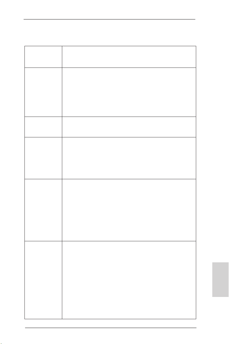
1.2 Speciche
Piattaforma - ATX Form Factor: 12.0-in x 9.6-in, 30.5 cm x 24.4 cm
- Design Premium Gold Capacitor (condensatori a polimeri
conduttivi di altissima qualità 100% made in Japan)
Processore - Supporta Intel® CoreTM i7 / i5 / i3 di 3a e 2a generazione in un
pacchetto LGA1155
- Design Digi Power
- Struttura di fase con alimentazione 8 + 4
- Supporto della tecnologia Intel® Turbo Boost 2.0
- Supporta CPU unlocked serie K
- Supporto tecnologia Hyper Threading
Chipset - Intel® Z77
- Supporta tecnologia Intel® Rapid Start Technology e Smart
Connect Technology
Memoria - Supporto tecnologia Dual Channel Memory
- 4 x slots DDR3 DIMM
- Supporto DDR3 2800+(OC)/2400(OC)/2133(OC)/1866(OC)/
1600/1333/1066 non-ECC, momoria senza buffer
- Capacità massima della memoria di sistema: 32GB
- Supporto di Intel® XMP (Extreme Memory Prole)1.3/1.2
Slot di - 2 x Alloggio PCI Express 3.0 x16 (PCIE2/PCIE4: singolo in
espansione modalità x16 (PCIE2) / x8 (PCIE4) o doppio in modalità x8/x8)
* PCIE 3.0 è supportato soltanto con la CPU Intel® Ivy Bridge.
Con la CPU Intel® Sandy Bridge, supporta solamente PCIE
2.0.
- 2 x Alloggio PCI Express 2.0 x1
- 2 x Alloggio PCI
- Supporto di AMD Quad CrossFireXTM e CrossFireX
- Supporto di NVIDIA® Quad SLITM e SLI
TM
VGA su scheda * Le uscite Intel® HD Graphics Built-in Visuals e VGA possono
essere supportate solo con processori dotati di GPU integrata.
- Supporta Intel® HD Graphics Built-in Visuals: Intel® Quick Sync
Video 2.0, Intel® InTruTM 3D, Intel® Clear Video HD Technology,
Intel® InsiderTM e Intel® HD Graphics 2500/4000
- Pixel Shader 5.0, DirectX 11 con CPU Intel® Ivy Bridge, Pixel
Shader 4.1, DirectX 10.1 con CPU Intel® Sandy Bridge
- Memoria massima condivisa 1760MB
- Tre opzioni d’output VGA: D-Sub, HDMI e Thunderbolt
- Supporta HDMI 1.4a con risoluzione massima no a
1920x1200 @ 60Hz
TM
Italiano
ASRock Z77 Extreme6/TB4 Motherboard
81
Page 82

Italiano
- Supporta D-Sub con risoluzione massima no a 2048x1536 @
75Hz
- Supporta Thunderbolt con risoluzione massima no a
2560x1600 @ 60Hz
- Supporto Auto Lip Sync, Deep Color (12bpc), xvYCC e HBR
(High Bit Rate Audio) con HDMI
- Supporto HDCP con le porte HDMI
- Supporto 1080p Blu-ray (BD) / HD-DVD riproduzione con le
porte HDMI
- Supporta velocità di trasferimento dati no a 10Gbp con porta
Thunderbolt
- Supporta collegamenti a margherita no a un massimo di 6
dispositivi Thunderbolt
Audio - 7.1 CH HD Audio con protezioni contenuti
(Realtek ALC898 Audio Codec)
- Supporto audio Blu-ray Premium
- Supporto THX TruStudio
TM
LAN - PCIE x1 Gigabit LAN 10/100/1000 Mb/s
- Broadcom BCM57781
- Supporta Wake-On-LAN
- Supporto di Energy Efcient Ethernet 802.3az
- Supporta PXE
Pannello - 1 x porta PS/2 per mouse/tastiera
posteriore I/O - 1 x porta D-Sub
- 1 x porta HDMI
- 1 x Ingresso porta di visualizzazione per porta Thunderbolt
(TBT2)(Solo le per prove)
- 2 x porteThunderbolt
- 1 x porta ottica SPDIF Out
- 2 x porte USB 2.0 già integrate
- 1 x connettore eSATA3
- 4 x porte USB 3.0 già integrate
- 1 x porte LAN RJ-45 con LED (LED azione/collegamento e
LED velocità)
- 1 x porte IEEE 1394
- 1 x interruttore di pulizia CMOS
- Connettore HD Audio: cassa posteriore / cassa centrale /
bassi / ingresso linea / cassa frontale / microfono
SATA 3 - 2 x Connettori SATA3 6,0Gb/s Z77 Intel®, supporto RAID
(RAID 0, RAID 1, RAID 5, RAID 10, Intel Rapid Storage e
tecnologia Intel Smart Response), NCQ, AHCI e Hot Plug
82
ASRock Z77 Extreme6/TB4 Motherboard
Page 83

- 2 x Connettori SATA3 6,0Gb/s ASM1061 ASMedia, supporto
NCQ, AHCI e Hot Plug (il connettore SATA3_A2 è condiviso
con la porta eSATA)
USB 3.0 - 2 x porte USB 3.0 posteriori amministrate dal controller Z77®,
supporto di USB 1.1/2.0/3.0 no a 5Gb/s
- 2 x porte USB 3.0 posteriori amministrate dal controller
ASMedia ASM1042, supporto di USB 1.1/2.0/3.0 no a 5Gb/s
- 1 x header USB 3.0 frontale (supporta 2 porte USB 3.0)
amministrato dal controller Z77®, supporto di USB 1.1/2.0/3.0
no a 5Gb/s
Connettori - 4 x connettori SATA2 3.0Go/s, sopporta RAID (RAID 0, RAID 1,
RAID 5, RAID 10, Intel Rapid Storage e tecnologia Intel Smart
Response), NCQ, AHCI e Hot Plug
- 4 x connettori SATA3 6.0Go/s
- 1 x Collettore modulo infrarossi
- 1 x Collettore modulo infrarosso consumer
- 1 x collettore porta COM
- 1 x connettore HDMI_SPDIF
- 1 x collettore IEEE 1394
- 1 x LED di accensione
- 2 x connettori CPU ventola (1 x 4-pin, 1 x 3-pin)
- 3 x connettori Chassis ventola (1 x 4-pin, 2 x 3-pin)
- 1 x connettore Alimentazione ventola (3-pin)
- 24-pin collettore alimentazione ATX
- 8-pin connettore ATX 12V
- Collettore alimentazione SLI/XFIRE
- Connettore audio sul pannello frontale
- 3 x Collettore USB 2.0 (supporta 6 porte USB 2.0)
- 1 x Collettore USB 3.0 (supporta 2 porte USB 3.0)
- 1 x Dr. Debug (LED debug con 7 segmenti)
- 1 x interruttore pulizia CMOS con LED
- 1 x interruttore di alimentazione con LED
- 1 x interruttore di reset con LED
BIOS - 64Mb AMI UEFI Legal BIOS con interfaccia di supporto
- Supporta “Plug and Play”
- Compatibile con ACPI 1.1 wake up events
- Supporta jumperfree
- Supporta SMBIOS 2.3.1
- Regolazione multi-voltaggio CPU Core, IGPU, DRAM, 1.8V
PLL, VTT, VCCSA
CD di - Driver, Utilità, Software AntiVirus (versione di prova),
Italiano
ASRock Z77 Extreme6/TB4 Motherboard
83
Page 84

supporto CyberLink MediaEspresso 6.5 Trial, Suite multimediale
ASRock MAGIX - OEM, Browser e barra degli strumenti
Google Chrome
Monitoraggio - Sensore per la temperatura del processore/Chassis
Hardware - Indicatore di velocità per la ventola del CPU/Chassis/potenza
Alimentazione
- Ventola CPU/Chassis silenziosa (permette la regolazione
automatica della ventola dello chassis in base alla temperatura
della CPU)
- Ventola CPU/chassis con controllo di varie velocità
- Voltaggio: +12V, +5V, +3.3V, Vcore
Compatibilità - Microsoft® Windows® 8 / 8 64 bit / 7 / 7 64 bit / VistaTM / VistaTM
SO 64 bit / XP / XP 64 bit
Certicazioni - FCC, CE, WHQL
- Predisposto ErP/EuP (è necessaria l’alimentazione
predisposta per il sistema ErP/EuP)
* Per ulteriori informazioni, prego visitare il nostro sito internet: http://www.asrock.com
AVVISO
Si prega di prendere atto che la procedura di overclocking implica dei rischi, come
anche la regolazione delle impostazioni del BIOS, l’applicazione della tecnologia
Untied Overclocking Technology, oppure l’uso di strumenti di overclocking forniti da
terzi. L’overclocking può inuenzare la stabilità del sistema, ed anche provocare
danni ai componenti ed alle periferiche del sistema. La procedura è eseguita a pro
prio rischio ed a proprie spese. Noi non possiamo essere ritenuti responsabili per
possibili danni provocati dall’overclocking.
Italiano
84
ASRock Z77 Extreme6/TB4 Motherboard
Page 85

1.3 Setup dei Jumpers
L’illustrazione mostra come sono settati i jumper. Quando il ponticello è posizionato sui pin,
il jumper è “CORTOCIRCUITATO”. Se sui pin
non ci sono ponticelli, il jumper è “APERTO”.
L’illustrazione mostra un jumper a 3 pin in cui il
pin1 e il pin2 sono “CORTOCIRCUITATI” quando il ponticello è posizionato su questi pin.
Jumper Settaggio del Jumper
Resettare la CMOS
(CLRCMOS1)
(vedi p.2 Nr. 21)
Nota:
CLRCMOS1 permette si azzerare i dati nella CMOS. Per cancellare e ripristinare
i
parametri del sistema sulla congurazione iniziale, spegnere il computer e
Impostazione
predenita
scollegare il cavo d’alimentazione dalla presa di corrente. Attendere 15 secondi,
poi usare un cappuccio jumper per cortocircuitare il pin 2 ed il pin 3 su
CLRCMOS1 per 5 secondi. Tuttavia, si consiglia di non cancellare la CMOS
subito dopo avere aggiornato il BIOS. Se si deve azzerare la CMOS quando si
è completato l’aggiornamento del BIOS, è necessario per prima cosa avviare il
sistema e poi spegnerlo prima di eseguire l’azzeramento della CMOS. Notare
che password, data, ore, prolo utente predenito, 1394 GUID e indirizzo MAC
saranno cancellati solo se è rimossa la batteria della CMOS.
Azzeramen-
to CMOS
L’interruttore Clear CMOS (Cancella CMOS) ha la stessa funzione del
jumper Clear CMOS.
ASRock Z77 Extreme6/TB4 Motherboard
Italiano
85
Page 86

1.4 Collettori e Connettori su Scheda
I collettori ed i connettori su scheda NON sono dei jumper. NON installare cappucci per jumper su questi collettori e connettori. L’installazione
di cappucci per jumper su questi collettori e connettori provocherà
danni permanenti alla scheda madre!
Connettori Serial ATA2 Questi quattro connettori Serial
(SATA2_2_3: vedi p.2 Nr. 13)
(SATA2_4_5: vedi p.2 Nr. 14)
immagazzinamento interni.
L’interfaccia SATA2 attuale
permette velocità di
trasferimento dati no a 3.0
Gb/s.
Serial ATA3 Connectors Questi quattro connettori Serial
(SATA3_A1_A2: vedi p.2 Nr. 11)
(SATA3_0_1: vedi p.2 Nr. 12)
immagazzinamento interni.
L’interfaccia SATA3 attuale
permette velocità di
trasferimento dati no a 6.0
Gb/s. Se si è collegata la porta
eSATA sull’I/O posteriore, la
SATA3_A2 interna non
funziona.
ATA2 (SATA2) supportano cavi
dati SATA per dispositivi di
SATA2_4 SATA2_2
SATA2_5 SATA2_3
ATA3 (SATA3) supportano cavi
dati SATA per dispositivi di
SATA3_0 SATA3_A1
SATA3_1 SATA3_A2
Italiano
86
Cavi dati Serial ATA (SATA) Una o altra estremità del cavo
(Opzionale)
di dati SATA può essere
collegata al disco rigido SATA /
SATA2 / SATA3 o al connettore
di SATA2 / SATA3 su questa
cartolina base.
ASRock Z77 Extreme6/TB4 Motherboard
Page 87

Collettore USB 2.0 Oltre alle due porte USB 2.0
(9-pin USB_2_3)
(vedi p.2 Nr. 25)
predenite nel pannello I/O, la
scheda madre dispone di tre
intestazioni USB 2.0. Ciascuna
intestazione USB 2.0 supporta
due porte USB 2.0.
(9-pin USB_4_5)
(vedi p.2 Nr. 26)
(9-pin USB_6_7)
(vedi p.2 Nr. 27)
Collettore USB 3.0 Oltre alle quattro porte USB 3.0
(19-pin USB3_4_5)
(vedi p.2 Nr. 8)
standard del pannello I/O,
questa scheda madre è dotata
di un header USB 3.0 che
supporta due porte USB 3.0.
Collettore modulo infrarossi Questo collettore supporta
(5-pin IR1)
moduli ad infrarossi optional per
(vedi p.2 Nr. 30)
la trasmissione e la ricezione
senza li.
Connettore modulo infrarosso consumer Questo connettore può essere
(4-pin CIR1)
(vedi p.2 Nr. 28)
utilizzato per collegare
ricevitore remoto.
ASRock Z77 Extreme6/TB4 Motherboard
Italiano
87
Page 88

Connettore audio sul È un’interfaccia per il cavo del
pannello frontale pannello audio. Che consente
(9-pin HD_AUDIO1)
(vedi p.2 Nr. 32)
1. La caratteristica HDA (High Denition Audio) supporta il rilevamento dei
connettori, però il pannello dei cavi sul telaio deve supportare la funzione HDA
(High Denition Audio) per far sì che questa operi in modo corretto. Attenersi alle
istruzioni del nostro manuale e del manuale del telaio per installare il sistema.
2. Se si utilizza un pannello audio AC’97, installarlo nell’intestazione audio del
pannello anteriore, come indicato di seguito:
A. Collegare Mic_IN (MIC) a MIC2_L.
B. Collegare Audio_R (RIN) a OUT2_R e Audio_L (LIN) ad OUT2_L.
C. Collegare Ground (GND) a Ground (GND).
D. MIC_RET e OUT_RET sono solo per il pannello audio HD. Non è
necessario collegarli per il pannello audio AC’97.
E. Per attivare il microfono frontale.
Sistema operativo Windows® XP / XP 64-bit:
Selezionare “Mixer”. Selezionare “Recorder” (Registratore). Poi,
fare clic su “FrontMic” (Microfono frontale).
Sistema operativo Windows® 8 / 8 64-bit / 7 / 7 64-bit / VistaTM /
VistaTM 64-bit:
Andare alla scheda “FrontMic” (Microfono frontale) del pannello di
controllo Realtek. Regolare la voce “Recording Volume” (Volume
registrazione).
connessione facile e controllo
dei dispositivi audio.
Italiano
88
Collettore pannello di sistema Questo collettore accomoda
(9-pin PANEL1)
(vedi p.2 Nr. 20)
Collegare l’interruttore d’alimentazione, l’interruttore di ripristino,
l’indicatore di stato del sistema del pannello frontale del telaio a questo
header in base all’assegnazione dei pin denita di seguito. Determinare i
pin positivi e negativi prima di collegare i cavi.
PWRBTN (interruttore d’alimentazione):
diverse funzioni di sistema
pannello frontale.
Va collegato all’interruttore d’alimentazione del pannello frontale del
telaio. Usando l’interruttore d’alimentazione si può congurare il modo in
cui si spegne il sistema.
ASRock Z77 Extreme6/TB4 Motherboard
Page 89

RESET (interruttore di ripristino):
Va collegato all’interruttore di ripristino del pannello frontale del telaio.
Premere l’interruttore di ripristino per riavviare il sistema se il computer si
blocca e non riesce ad eseguire un normale riavvio.
PLED (LED alimentazione del sistema):
Va collegato all’indicatore di stato d’alimentazione del pannello frontale
del telaio. Il LED è acceso quando il sistema è operativo. Il LED continua
a lampeggiare quando il sistema è in stato di standby S1/S3. Il LED è
spento quando il sistema è in stato di sospensione /ibernazione S4
oppure spento (S5).
HDLED (LED attività disco rigido):
Va collegato al LED attività disco rigido del pannello frontale del telaio. Il
LED è acceso quando disco rigido legge e scrive i dati.
Il design del pannello frontale può variare in base ai telai. Il modulo di un
pannello frontale può consistere di: interruttore d’alimentazione,
interruttore di ripristino, LED d’alimentazione, LED attività disco rigido,
casse, eccetera. Quando si collega il modulo del pannello frontale a
questo header, assicurarsi che l’assegnazione dei li e dei pin sia fatta
corrispondere in modo appropriato.
Collettore casse telaio Collegare le casse del telaio a
(4-pin SPEAKER1)
(vedi p.2 Nr. 22)
questo collettore.
LED di accensione Collegare il LED di accensione
(3-pin PLED1)
(vedi p.2 Nr. 18)
chassi per indicare lo stato di
alimentazione del sistema. Il
LED è acceso quando il sistema
è in funzione. Il LED continua a
lampeggiare in stato S1/S3. Il
LED è spento in stato S4 o S5
(spegnimento).
ASRock Z77 Extreme6/TB4 Motherboard
Italiano
89
Page 90

Collettori Chassis ed alimentazione ventola Collegare i cavi della ventola ai
GND
+12V
FAN_SPEED
GND
+12V
FAN_SPEED
FAN_SPEED
FAN_SPEED_CONTROL
+12V
GND
4
2
3
1
(4-pin CHA_FAN1)
(vedi p.2 Nr. 23)
corrispondenti connettori
facendo combaciare il cavo
nero col pin di terra.
(3-pin CHA_FAN2)
(vedi p.2 Nr. 41)
CHA_FAN1, CHA_FAN2 e
CHA_FAN3 supportano la
funzione Fan Control.
(3-pin CHA_FAN3)
(vedi p.2 Nr. 24)
Italiano
(3-pin PWR_FAN1)
(vedi p.2 Nr. 9)
FAN_SPEED
+12V
GND
Connettore ventolina CPU Collegare il cavo della ventolina
(4-pin CPU_FAN1)
(vedi p.2 Nr. 3)
CPU a questo connettore e far
combaciare il lo nero al pin
terra.
Sebbene la presente scheda madre disponga di un supporto per ventola CPU a 4
piedini (ventola silenziosa), la ventola CPU a 3 piedini è in grado di funzionare
anche senza la funzione di controllo della velocità della ventola. Se si intende
collegare la ventola CPU a 3 piedini al connettore della ventola CPU su questa
scheda madre, collegarla ai piedini 1-3.
Installazione della ventola a 3 piedini
(3-pin CPU_FAN2)
(vedi p.2 Nr. 4)
Connettore alimentazione ATX Collegare la sorgente
(24-pin ATXPWR1)
(vedi p.2 Nr. 7)
d’alimentazione ATX a questo
connettore.
FAN_SPEED
+12V
GND
12 124
Piedini 1-3 collegati
90
13
ASRock Z77 Extreme6/TB4 Motherboard
Page 91
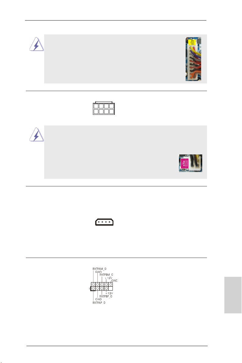
Con questa scheda madre, c’è in dotazione un
connettore elettrico ATX a 24 pin, ma può funzionare lo
stesso se si adotta un alimentatore ATX a 20 pin. Per
usare l’alimentatore ATX a 20 pin, collegare l’alimentatore
con il Pin 1 e il Pin 13.
12
24
Installazione dell’alimentatore ATX a 20 pin
Connettore ATX 12 V Collegare un alimentatore ATX
(8-pin ATX12V1)
(vedi p.2 Nr. 1)
12 V a questo connettore.
8 5
4 1
1
13
Sebbene questa schedamadre fornisca un connettore elettrico 8-pin ATX 12V,
l‘unita‘ puo‘ ancora essere funzionante se viene utilizzata una fornitura elettrica
tradizionale a 4-pin ATX 12V. Per usare tale fornitura elettrica 4-pin ATX 12V,
prego collegare la presa elettrica al Pin 1 e Pin 5.
Installazione elettrica 4-Pin ATX 12V
8 5
4 1
4Connettore alimentazione SLI/XFIRE Non è necessario usare questo
(4-pin SLI/XFIRE_POWER1)
(vedi p.2 Nr. 40)
connettore, però deve essere
collegatoad un connettore
d’alimentazione disco rigido
quando sulla scheda madre
sono installate
SLI/XFIRE_POWER1
contemporaneamente due
schede video.
Intestazione IEEE 1394 Accanto alla porta di default
(9-pin FRONT_1394)
(vedi p.2 Nr. 19)
IEEE 1394 sul pannello I/O, e‘
presente un‘intestazione IEEE
1394 (FRONT_1394) sulla
scheda madre. Questa
intestazione IEEE 1394 puo‘
supportare una porta IEEE
1394.
ASRock Z77 Extreme6/TB4 Motherboard
Italiano
91
Page 92

Collettore porta COM Questo collettore porta COM è
(9-pin COM1)
(vedi p.2 Nr. 31)
utilizzato per supportare il
modulo porta COM.
Header HDMI_SPDIF Header HDMI_SPDIF, con
(2-pin HDMI_SPDIF1)
(vedi p.2 Nr. 33)
uscita audio SPDIF su scheda
HDMI VGA, consente al
sistema di collegare dispositivi
per TV digitale HDMI/proiettori/
LCD . Collegare il connettore
HDMI_SPDIF della scheda
VGA HDMI a questo header.
Italiano
92
ASRock Z77 Extreme6/TB4 Motherboard
Page 93

1.5 Interruttori rapidi
Questa scheda madre ha tre interruttori rapidi: Interruttore di alimentazione, interruttore di reset e interruttore pulizia CMOS, che consentono agli utenti di accendere /
spegnere rapidamente o cancellare i valori CMOS.
Interruttore di alimentazione L’interruttore di alimentazione è
(PWRBTN)
(vedi p.2 Nr. 17)
accendere/spegnere
rapidamente il sistema.
Interruttore di reset L’interruttore di reset è un
(RSTBTN)
(vedi p.2 Nr. 16)
rapidamente il sistema.
Interruttore pulizia CMOS L’interruttore di pulizia CMOS è
(CLRCBTN)
(vedi p.3 Nr. 18)
cancellare velocemente i valori
CMOS.
un interruttore rapido che
consente agli utenti di
interruttore rapido che consente
agli utenti di resettare
un interruttore rapido che
consente agli utenti di
ASRock Z77 Extreme6/TB4 Motherboard
Italiano
93
Page 94

2. Informazioni sul BIOS
La Flash Memory sulla scheda madre contiene le Setup Utility. Quando si avvia il
computer, premi <F2> o <Del> durante il Power-On-Self-Test (POST) della Setup
utility del BIOS; altrimenti, POST continua con i suoi test di routine. Per entrare il
BIOS Setup dopo il POST, riavvia il sistema premendo <Ctl> + <Alt> + <Delete>, o
premi il tasto di reset sullo chassis del sistema. Per informazioni più dettagliate circa
il Setup del BIOS, fare riferimento al Manuale dell’Utente (PDF le) contenuto nel cd
di supporto.
3. Software di supporto e informazioni su
CD
Questa scheda madre supporta vari sistemi operativi Microsoft® Windows®: 8 / 8 64bit / 7 / 7 64-bit / VistaTM / Vista
della scheda madre contiene i driver e utilità necessari a potenziare le caratteristiche della scheda.
Inserire il CD di supporto nel lettore CD-ROM. Se la funzione “AUTORUN” è attivata
nel computer, apparirà automaticamente il Menù principale. Se il Menù principale
non appare automaticamente, posizionarsi sul le “ASRSETUP.EXE” del CD di sup-
porto e cliccare due volte per visualizzare i menù.
TM
64-bit / XP / XP 64-bit. Il CD di supporto a corredo
Italiano
94
ASRock Z77 Extreme6/TB4 Motherboard
Page 95

1. Introducción
Gracias por su compra de ASRock Z77 Extreme6/TB4 placa madre, una placa de
conanza producida bajo el control de calidad estricto y persistente. La placa madre
provee realización excelente con un diseño robusto conforme al compromiso de
calidad y resistencia de ASRock.
Esta Guía rápida de instalación contiene una introducción a la placa base y una
guía de instalación paso a paso. Puede encontrar una información más detallada
sobre la placa base en el manual de usuario incluido en el CD de soporte.
Porque las especicaciones de la placa madre y el software de BIOS
podrían ser actualizados, el contenido de este manual puede ser cambiado
sin aviso. En caso de cualquier modicación de este manual, la versión
actualizada estará disponible en el website de ASRock sin previo aviso.
También encontrará las listas de las últimas tarjetas VGA y CPU soportadas
en la página web de ASRock.
Website de ASRock http://www.asrock.com
Si necesita asistencia técnica en relación con esta placa base, visite nuestra
página web con el número de modelo especíco de su placa.
www.asrock.com/support/index.asp
1.1 Contenido de la caja
Placa base ASRock Z77 Extreme6/TB4
(Factor forma ATX: 30,5 cm x 24,4 cm, 12,0” x 9,6”)
Guía de instalación rápida de ASRock Z77 Extreme6/TB4
CD de soporte de ASRock Z77 Extreme6/TB4
Seis cables de datos Serial ATA (SATA) (Opcional)
Una protección I/O
Una tarjeta ASRock SLI_Bridge_2S
ASRock Z77 Extreme6/TB4 Motherboard
Español
95
Page 96

Español
1.2 Especicación
Plataforma - Factor forma ATX: 30,5 cm x 24,4 cm, 12,0” x 9,6”
- Diseño de condensadores de oro de calidad superior
(condensadores de polímero conductor de alta calidad de
fabricación 100% japonesa)
Procesador - Admite procesadores Intel® CoreTM i7 / i5 / i3 de la 3ª y 2ª
generación en el paquete LGA1155
- Diseño de alimentación digital
- Diseño de fases de potencia 8 + 4
- Admite la tecnología Intel® Turbo Boost 2.0 Technology
- Admite procesador desbloqueado de la serie K
- Admite tecnología Hyper Threading
Chipset - Intel® Z77
- Admite las tecnologías Intel® Rapid Start y Smart Connect
Memoria - Soporte de Tecnología de Memoria de Doble Canal
- 4 x DDR3 DIMM slots
- Apoya DDR3 2800+(OC)/2400(OC)/2133(OC)/1866(OC)/
1600/1333/1066 non-ECC, memoria de un-buffered
- Máxima capacidad de la memoria del sistema: 32GB
- Compatible con Intel® Extreme Memory Prole (XMP)1.3/1.2
Ranuras de - 2 x ranuras PCI Express 3.0 x16 (PCIE2/PCIE4: único a x16
Expansión (PCIE2) / x8 (PCIE4) o dual en modo x8/x8)
* PCIE 3.0 solamente se admite con una CPU Intel® Ivy
Bridge. Con una CPU Intel® Sandy Bridge, solamente
admite PCIE 2.0.
- 2 x ranuras PCI Express 2.0 x1
- 2 x ranuras PCI
- Compatible con AMD Quad CrossFireXTM y CrossFireX
- Compatible con NVIDIA® Quad SLITM y SLI
TM
VGA OnBoard * Los efectos visuales incorporados con grácos de alta
denición Intel® y las salidas VGA sólo se soportan con
procesadores con GPU integrada.
- Admite Intel® HD Graphics Built-in Visuals: Intel® Quick Sync
Video, Intel® InTruTM 3D, Intel® Clear Video HD Technology,
Intel® InsiderTM y Intel® HD Graphics 2500/4000
- Pixel Shader 5.0, DirectX 11 con CPU Intel® Ivy Bridge, Pixel
Shader 4.1, DirectX 10.1 con CPU Intel® Sandy Bridge
- 1760MB de Memoria máxima compartida
- Tres opciones de salida VGA: D-Sub, HDMI y Thunderbolt
- Admite HDMI 1.4a con una resolución máxima de 1920x1200
TM
96
ASRock Z77 Extreme6/TB4 Motherboard
Page 97

a 60 Hz
- Admite D-Sub con una resolución máxima de 2048x1536 a
75 Hz
- Admite Thunderbolt con una resolución máxima de
2560x1600 a 60 Hz
- Admite Sincronización automática entre audio y vídeo, Deep
Color (12 bpc), xvYCC y HBR (audio de alta tasa de bits) con
HDMI
- Admite HDCP con puerto HDMI
- Apoya la reproducción de Blu-rayo de 1080p (BD) / HD-DVD
con puerto HDMI
- Admite tasas de transferencia de datos de hasta 10 Gbps
con puerto Thunderbolt
- Admite conguración en cadena de hasta 6 dispositivos
Thunderbolt
Audio - 7.1 CH HD Audio con Protección de Contenido
(Realtek ALC898 Audio Codec)
- Compatible con audio Blu-ray de alta calidad
- Compatible con THX TruStudio
TM
LAN - PCIE x1 Gigabit LAN 10/100/1000 Mb/s
- Broadcom BCM57781
- Soporta Wake-On-LAN
- Compatible con Ethernet 802.3az de bajo consumo
energético
- Compatible con PXE
Entrada/Salida de - 1 x puerto de ratón/teclado PS/2
Panel Trasero - 1 x puerto D-Sub
- 1 x puerto HDMI
- 1 x Entrada DisplayPort para puerto Thunderbolt (TBT2)(Para
la prueba)
- 2 x puertos Thunderbolt
- 1 x puerto de salida óptica SPDIF
- 2 x puertos USB 2.0 predeterminados
- 1 x Conector eSATA3
- 4 x puertos USB 3.0 predeterminados
- 1 x Puerto LAN RJ-45 con LED (LED de ACCIÓN/ENLACE y
LED de VELOCIDAD)
- 1 x puerto IEEE 1394
- 1 x conmutador de borrado de memoria CMOS
- Conexión de audio: Altavoz trasero / Central / Bajos /
Entrada de línea / Altavoz frontal / Micrófono
Español
ASRock Z77 Extreme6/TB4 Motherboard
97
Page 98

Español
SATA 3 - 2 x conectores SATA3 de 6,0 Gb/s con chip Intel® Z77
soporta RAID (RAID 0, RAID 1, RAID 5, RAID 10, Intel Rapid
Storage y tecnología Intel Smart Response), NCQ, AHCI y
de Hot Plug
- 2 x conectores SATA3 de 6,0 Gb/s con chip ASMedia
ASM1061 soporta NCQ, AHCI y de Hot Plug (los puertos
SATA3_A2 y eSATA son compartidos)
USB 3.0 - 2 x puertos USB 3.0 traseros de Intel® Z77, compatible con
USB 1.1/2.0/3.0 de hasta 5 GB/s
- 2 x puertos USB 3.0 traseros de ASMedia ASM1042,
compatible con USB 1.1/2.0/3.0 de hasta 5 GB/s
- 1 x cabecera USB 3.0 delantera (compatible con 2 puertos
USB 3.0) de Intel® Z77, compatible con USB 1.1/2.0/3.0 de
hasta 5 GB/s
Conectores - 4 x conectores SATA2 de 3,0 Gb/s con chip Intel® Z77
soporta RAID (RAID 0, RAID 1, RAID 5, RAID 10, Intel Rapid
Storage y tecnología Intel Smart Response), NCQ, AHCI y
de Hot Plug
- 4 x conectores SATA3 de 6,0 Gb/s
- 1 x cabezal de Módulo Infrarrojos
- 1 x Base de conexiones del módulo de infrarrojos para el
consumidor
- 1x En-tête de port COM
- 1 x cabecera HDMI_SPDIF
- 1 x cabecera IEEE 1394
- 1 x cabecera de indicador LED de encendido
- 2 x conectores de ventilador de CPU (1 x 4-pin, 1 x 3-pin)
- 3 x conectores de ventilador de chasis (1 x 4-pin, 2 x 3-pin)
- 1 x conector de ventilador de alimentacion (3-pin)
- 24-pin cabezal de alimentación ATX
- 8-pin conector de ATX 12V power
- Cabezal de alimentación SLI/XFIRE
- Conector de audio de panel frontal
- 3 x Cabezal USB 2.0 (admite 6 puertos USB 2.0 adicionales)
- 1 x Cabezal USB 3.0 (admite 2 puertos USB 3.0 adicionales)
- 1 x Dr. Debug (indicador LED de avería de 7 segmentos)
- 1 x conmutador de encendido con indicador LED
- 1 x conmutador de reinicio con indicador LED
- 1 x conmutador de borrado de memoria CMOS con
indicador LED
BIOS - 64Mb AMI BIOS legal UEFI AMI compatible con GUI
98
ASRock Z77 Extreme6/TB4 Motherboard
Page 99

- Soporta “Plug and Play”
- ACPI 1.1 compliance wake up events
- Soporta “jumper free”
- Soporta SMBIOS 2.3.1
- Múltiple ajuste de CPU Core, IGPU, DRAM, 1.8V PLL, VTT,
VCCSA Voltage
CD de soport - Controladores, utilidades, software de antivirus (versión de
prueba), Prueba de CyberLink MediaEspresso 6.5, Conjunto
multimedia ASRock MAGIX - OEM, Explorador y barra de
herramientas Google Chrome
Monitor - Sensibilidad a la temperatura del procesador/chasis
Hardware - Taquímetros de los ventiladores del procesador y del CPU /
chasis / alimentación
- Ventilador silencioso del procesador y el chasis (ajuste
automático de la velocidad del ventilador del chasis en
función de la temperatura del procesador)
- Control de ajuste de la velocidad del ventilador de la CPU /
chasis
- Monitor de Voltaje: +12V, +5V, +3.3V, Vcore
OS - En conformidad con Microsoft® Windows® 8 / 8 64 bits / 7 / 7
64 bits / VistaTM / VistaTM 64 bits / XP / XP 64 bits
Certicaciones - FCC, CE, WHQL
- Cumple con la directiva ErP/EuP (se requiere una fuente de
alimentación que cumpla con la directiva ErP/EuP)
* Para más información sobre los productos, por favor visite nuestro sitio web:
http://www.asrock.com
ADVERTENCIA
Tenga en cuenta que hay un cierto riesgo implícito en las operaciones de aumento
de la velocidad del reloj, incluido el ajuste del BIOS, aplicando la tecnología de
aumento de velocidad liberada o utilizando las herramientas de aumento de
velocidad de otros fabricantes. El aumento de la velocidad puede afectar a la
estabilidad del sistema e, incluso, dañar los componentes y dispositivos del sistema.
Esta operación se debe realizar bajo su propia responsabilidad y Ud. debe asumir
los costos. No asumimos ninguna responsabilidad por los posibles daños causados
por el aumento de la velocidad del reloj.
ASRock Z77 Extreme6/TB4 Motherboard
Español
99
Page 100

1.3 Setup de Jumpers
La ilustración muestra como los jumpers
son congurados. Cuando haya un jumper-
cap sobre los pins, se dice gue el jumper
está “Short”. No habiendo jumper cap sobre
los pins, el jumper está “Open”. La ilustración muesta un jumper de 3 pins cuyo
pin 1 y pin 2 están “Short”.
Jumper Setting
Limpiar CMOS
(CLRCMOS1, jumper de 3 pins)
(ver p.2, N. 21)
Nota:
CLRCMOS1 permite borrar los datos de la memoria CMOS. Para borrar los
parámetros del sistema y restablecer la conguración predeterminada de los mismos,
apague el equipo y desenchufe el cable de alimentación de la toma de corriente
eléctrica. Deje que transcurran 15 segundos y, después, utilice un puente
cortocircuitar los contactos 2 y 3 de CLRCMOS1 durante 5 segundos. No borre
la memoria CMOS justamente después de actualizar el BIOS. Si necesita borrar
la memoria CMOS justamente después de actualizar el BIOS, debe iniciar primero
el sistema y, a continuación, cerrarlo antes de llevar a cabo el borrado de
dicha memoria. Tenga en cuenta que la contraseña, la fecha, la hora, el perl
predeterminado del usuario, el GUID 1394 y la dirección MAC solamente se
borrará si la batería CMOS se quita.
Valor predeterminado
Restablecimiento de
la CMOS
para
Español
100
El conmutador Borrar CMOS tiene la misma función que el puente
Borrar CMOS.
ASRock Z77 Extreme6/TB4 Motherboard
 Loading...