

Page 1
Copyright Notice:
No part of this installation guide may be reproduced, transcribed, transmitted, or translated in any language, in any form or by any means, except duplication of documentation
by the purchaser for backup purpose, without written consent of ASRock Inc.
Products and corporate names appearing in this guide may or may not be registered
trademarks or copyrights of their respective companies, and are used only for identication or explanation and to the owners’ benet, without intent to infringe.
Disclaimer:
Specications and information contained in this guide are furnished for informational use
only and subject to change without notice, and should not be constructed as a commitment by ASRock. ASRock assumes no responsibility for any errors or omissions that may
appear in this guide.
With respect to the contents of this guide, ASRock does not provide warranty of any kind,
either expressed or implied, including but not limited to the implied warranties or condi-
tions of merchantability or tness for a particular purpose. In no event shall ASRock, its
directors, ofcers, employees, or agents be liable for any indirect, special, incidental, or
consequential damages (including damages for loss of prots, loss of business, loss of
data, interruption of business and the like), even if ASRock has been advised of the possibility of such damages arising from any defect or error in the guide or product.
This device complies with Part 15 of the FCC Rules. Operation is subject to the following
two conditions:
(1) this device may not cause harmful interference, and
(2) this device must accept any interference received, including interference that may
cause undesired operation.
CALIFORNIA, USA ONLY
The Lithium battery adopted on this motherboard contains Perchlorate, a toxic substance
controlled in Perchlorate Best Management Practices (BMP) regulations passed by the
California Legislature. When you discard the Lithium battery in California, USA, please
follow the related regulations in advance.
“Perchlorate Material-special handling may apply, see
www.dtsc.ca.gov/hazardouswaste/perchlorate”
ASRock Website: http://www.asrock.com
Published September 2012
Copyright©2012 ASRock INC. All rights reserved.
ASRock Z77 Extreme11 Motherboard
English
1
Page 2
ATX12V1
SLI/XFIRE_PWR1
DDR3 _A2 (64 b it, 240 -pin mo dule)
DDR3 _A1 (64 b it, 240 -pin mo dule)
DDR3 _B2 (64 b it, 240 -pin mo dule)
DDR3 _B1 (64 b it, 240 -pin mo dule)
CPU_FAN1
CPU_FAN2
PWR_FAN1
ATXP WR1
64Mb
BIOS
1
USB3_11_1 2
1
USB3_9_1 0
CMOS
Battery
SATA3_0_1
SATA2_2_3
SATA2_4_5
SAS_0_1
SAS_2_3
SAS_4_5
SAS_6_7
Dr.
Debug
CHA_FAN1
CHA_FAN2
Supe r
I/O
PCIE3
PCIE2
PCIE5
PCIE7
PCIE1
PCIE4
PCIE6
1
HDMI_SPDIF1
COM1
1
1
HD_AUDIO1
IR1
1
FRONT_1394
1
USB6_7
1
CIR1
1
USB4_51USB2_3
1
MINI _PCIE 1
PLED1
1
CLRCMOS1
1
HDLED RESET
PLEDPWRBTN
PANEL1
1
1
SPEAKER1
RSTBTN
PWRBTN
Z77 Extreme11
CHA_FAN3
AUDIO
CODEC
26.7cm (10.5 in)
30. 5cm (12 .0 in)
1
USB 3.0
T: USB1
B: USB2
PS2
Keyboard/
Mouse
Clr
CMOS
USB 2.0
T: USB0
B: USB1
IEEE 13 94
eSATA_1
USB 3.0
T: USB3
B: USB4
HDMI1
Top:
RJ-45
USB 3.0
T: USB5
B: USB6
Top:
RJ-45
USB 3.0
T: USB7
B: USB8
Top:
Central /Bass
Center:
REAR SPK
Top:
LINE IN
Center:
FRONT
Bottom:
Optical
SPDIF
Bottom:
MIC IN
DDR3 3000+
Fro nt USB 3. 0
ErP/EuP Ready
RoHS
XFast LAN
XFast RAM
XFast USB
PCI Ex press 3 .0
2
3
4
5
6
7
8
9
10
11
12
13
14
15
16
17
18
19
20
21
23
22
24
25
26
27
28
29
30
3132
33
34
35
36
37
38
39
40
41
42
43
44
45
46
47
48
49
Vertical
TypeAUSB
USB8
PEX
8747
PEX
8608
Intel
Z77
LSI
2308
SB_FAN1
WIFI + BT
Module
Dual-Stack MOSFET
3-Wa y SLI
LSI SAS
2 oz Co pper PC B
English
2
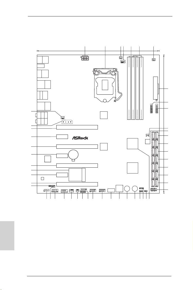
Motherboard Layout
1 ATX 12V Power Connector (ATX12V1)
2 1155-Pin CPU Socket
3 CPU Fan Connector (CPU_FAN2)
4 CPU Fan Connector (CPU_FAN1)
5 2 x 240-pin DDR3 DIMM Slots (DDR3_A1, DDR3_B1, Black)
6 2 x 240-pin DDR3 DIMM Slots (DDR3_A2, DDR3_B2, Black)
7 Power Fan Connector (PWR_FAN1)
8 ATX Power Connector (ATXPWR1)
9 USB 3.0 Header (USB3_11_12)
10 USB 3.0 Header (USB3_9_10)
ASRock Z77 Extreme11 Motherboard
Page 3

11 SB Fan Connector (SB_FAN1)
12 SPI Flash Memory (64Mb)
13 SATA3 Connector (SATA3_0_1, Gray)
14 SATA2 Connector (SATA2_2_3, Black)
15 SATA2 Connector (SATA2_4_5, Black)
16 SAS2/SATA3 Connector (SAS_0_1, Gray)
17 SAS2/SATA3 Connector (SAS_2_3, Gray)
18 SAS2/SATA3 Connector (SAS_4_5, Gray)
19 SAS2/SATA3 Connector (SAS_6_7, Gray)
20 System Panel Header (PANEL1)
21 Intel Z77 Chipset
22 Power LED Header (PLED1)
23 Chassis Speaker Header (SPEAKER1)
24 Clear CMOS Jumper (CLRCMOS1)
25 Power Switch (PWRBTN1)
26 Reset Switch (RSTBTN1)
27 Dr. Debug
28 Vertical Type A USB (USB8)
29 USB 2.0 Header (USB2_3)
30 USB 2.0 Header (USB4_5)
31 USB 2.0 Header (USB6_7)
32 Consumer Infrared Module Header (CIR1)
33 Chassis Fan Connector (CHA_FAN2)
34 Chassis Fan Connector (CHA_FAN1)
35 Front Panel IEEE 1394 Header (FRONT_1394)
36 COM Port Header (COM1)
37 Infrared Module Header (IR1)
38 Front Panel Audio Header (HD_AUDIO1)
39 HDMI_SPDIF Header (HDMI_SPDIF1)
40 PCI Express 2.0 x16 Slot (PCIE7)
41 PCI Express 2.0 x1 Slot (PCIE6)
42 Mini PCI Express Slot (MINI_PCIE1)
43 PCI Express 3.0 x16 Slot (PCIE5)
44 PCI Express 2.0 x1 Slot (PCIE4)
45 PCI Express 3.0 x16 Slot (PCIE3)
46 PCI Express 2.0 x1 Slot (PCIE2)
47 PCI Express 3.0 x16 Slot (PCIE1)
48 SLI/XFIRE Power Connector (SLI/XFIRE_PWR1)
49 Chassis Fan Connector (CHA_FAN3)
English
ASRock Z77 Extreme11 Motherboard
3
Page 4
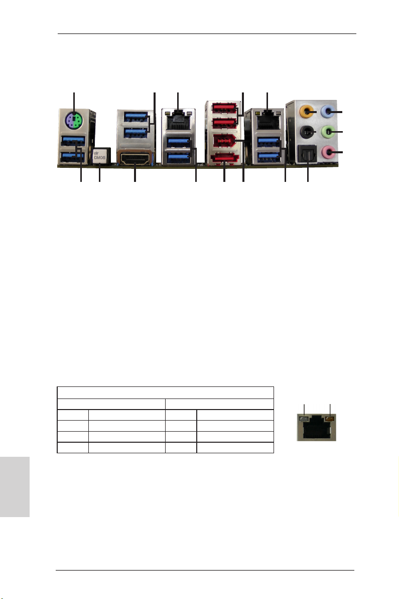
I/O Panel
1
3
2
5
4
6
8
9
7
10
18
17
1 PS/2 Keyboard/Mouse Port
2 USB 3.0 Ports (USB3_34)
*3 LAN RJ-45 Port
4 USB 2.0 Ports (USB01)
*5 LAN RJ-45 Port
6 Central / Bass (Orange)
7 Rear Speaker (Black)
8 Line In (Light Blue)
**9 Front Speaker (Lime)
* There are two LEDs on each LAN port. Please refer to the table below for the LAN
port LED indications.
16
15
10 Microphone (Pink)
11 Optical SPDIF Out Port
12 USB 3.0 Ports (USB3_78)
13 IEEE 1394 Port (1394)
***14 eSATA3 Connector (eSATA_1)
15 USB 3.0 Ports (USB3_56)
16 HDMI Port (HDMI1)
17 Clear CMOS Switch (CLRCBTN1)
18 USB 3.0 Ports (USB3_12)
14
13
12
11
English
4
LAN Port LED Indications
Activity/Link LED SPEED LED
Status Description Status Description
Off No Link Off 10Mbps connection
Blinking Data Activity Orange 100Mbps connection
On 100Mbps connection Green 1Gbps connection
ASRock Z77 Extreme11 Motherboard
ACT/LINK
LED
LAN Port
SPEED
LED
Page 5
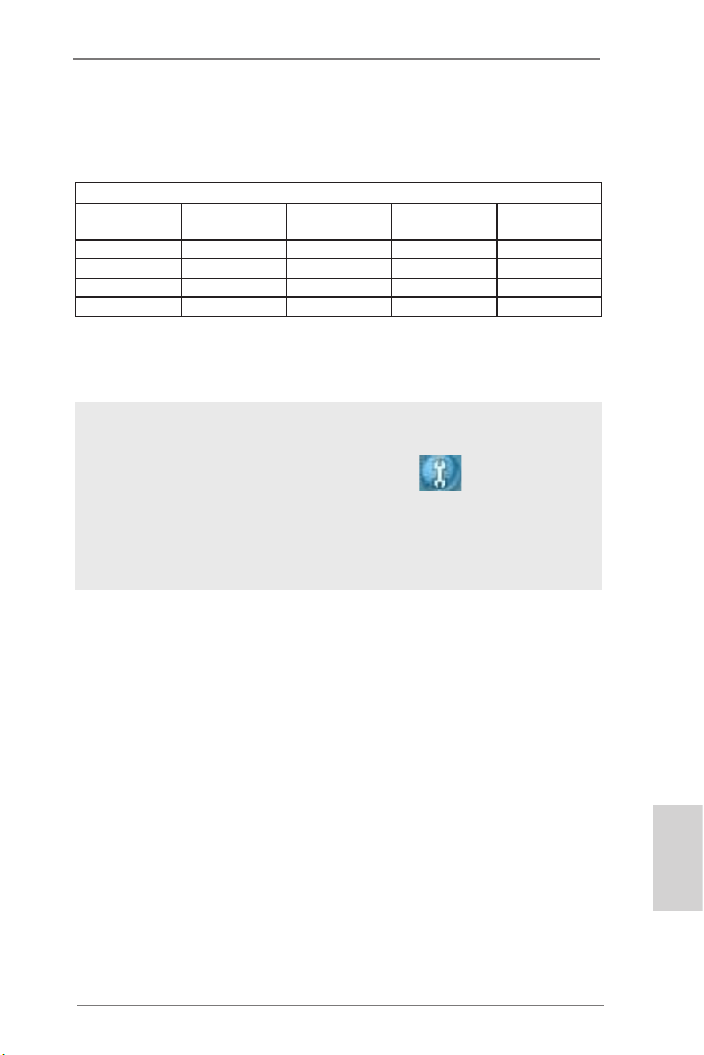
** If you use a 2-channel speaker, please connect the speaker’s plug into “Front
Speaker Jack”. See the table below for connection details in accordance with the
type of speaker you use.
TABLE for Audio Output Connection
Audio Output
Channels
2 V -- -- -4 V V -- -6 V V V -8 V V V V
To enable Multi-Streaming, you need to connect a front panel audio cable to the
front panel audio header. After restarting your computer, you will nd the “Mixer”
tool on your system. Please select “Mixer ToolBox” , click “Enable playback multi-streaming”, and click “ok”.
Choose “2CH”, “4CH”, “6CH”, or “8CH” and then you are allowed to select “Realtek
HDA Primary output” to use the Rear Speaker, Central/Bass, and Front Speaker,
or select “Realtek HDA Audio 2nd output” to use the front panel audio.
Front Speaker
(No. 9)
Rear Speaker
(No. 7)
Central / Bass
(No. 6)
Line In
(No. 8)
*** eSATA3 connector supports SATA Gen3 in cable 1M.
ASRock Z77 Extreme11 Motherboard
English
5
Page 6
1. Introduction
Thank you for purchasing ASRock Z77 Extreme11 motherboard, a reli-
able motherboard produced under ASRock’s consistently stringent quality
control. It delivers excellent performance with robust design conforming to
ASRock’s commitment to quality and endurance.
In this manual, chapter 1 and 2 contains the introduction of the motherboard and step-by-step hardware installation guide. Chapter 3 and 4 con-
tains the conguration guide of BIOS setup and information of the Support
CD.
Because the motherboard specications and the BIOS software
might be updated, the content of this manual will be subject to
change without notice. In case any modications of this manual
occur, the updated version will be available on ASRock’s web-
site without further notice. You may nd the latest VGA cards
and CPU support list on ASRock’s website as well. ASRock
website http://www.asrock.com
If you require technical support related to this motherboard,
please visit our website for specic information about the model
you are using.
www.asrock.com/support/index.asp
English
6
1.1 Package Contents
ASRock Z77 Extreme11 Motherboard
(EATX Form Factor: 12.0-in x 10.5-in, 30.5 cm x 26.7 cm)
ASRock Z77 Extreme11 Quick Installation Guide
ASRock Z77 Extreme11 Support CD
8 x Serial ATA (SATA) Data Cables
2 x Serial ATA (SATA) HDD Power Cables
1 x I/O Panel Shield
1 x ASRock SLI_Bridge_3S Card
1 x ASRock 3-Way SLI Bridge Card
1 x ASRock Wi-SB Box
12 x Screws
ASRock Z77 Extreme11 Motherboard
Page 7
1.2 Specications
Platform - EATX Form Factor: 12.0-in x 10.5-in, 30.5 cm x 26.7
cm
- 2oz copper PCB
- Premium Gold Capacitor design (100% Japan-made
high-quality Conductive Polymer Capacitors)
CPU - Supports 3rd and 2nd Generation Intel® CoreTM i7 / i5
/ i3 in LGA1155 Package
- Digi Power Design
- 8 + 4 Power Phase Design
- Dual-Stack MOSFET (DSM)
- Supports Intel® Turbo Boost 2.0 Technology
- Supports Intel® K-Series unlocked CPU
- Supports Hyper-Threading Technology
Chipset - Intel® Z77
- Supports Intel® Rapid Start Technology and Smart
Connect Technology
Memory - Dual Channel DDR3 Memory Technology
- 4 x DDR3 DIMM slots
- Supports DDR3 3000+(OC)/2400(OC)/2133(OC)/
1866(OC)/1600/1333/1066 non-ECC, un-buffered
memory
- Max. capacity of system memory: 32GB
(see CAUTION 1)
- Supports Intel® Extreme Memory Prole (XMP)1.3/1.2
Expansion Slot - 3 x PCI Express 3.0 x16 slots (PCIE1/PCIE5: single
at x16 (PCIE1)/x8(PCIE5) or dual at x8/x8; PCIE3: x8
mode)
* PCIE 3.0 is only supported with Intel® Ivy Bridge
CPU. With Intel® Sandy Bridge CPU, it only supports
PCIE 2.0.
- 1 x PCI Express 2.0 x16 slot (PCIE7: x4 mode)
- 3 x PCI Express 2.0 x1 slots
- 1 x mini-PCI Express slot: For WiFi + BT module
- PLX PEX 8747 and PLX PEX 8608 embedded
- Supports AMD Quad CrossFireXTM, 4-Way
English
ASRock Z77 Extreme11 Motherboard
7
Page 8
English
CrossFireXTM, 3-Way CrossFireXTM and CrossFireX
TM
- Supports NVIDIA® Quad SLITM, 3-Way SLITM and
SLI
TM
Graphics * Intel® HD Graphics Built-in Visuals and the VGA
outputs can be supported only with processors which
are GPU integrated.
- Supports Intel® HD Graphics Built-in Visuals : Intel®
Quick Sync Video 2.0, Intel® InTruTM 3D, Intel® Clear
Video HD Technology, Intel® InsiderTM, Intel® HD
Graphics 2500/4000 with Intel® Ivy Bridge CPU
- Supports Intel® HD Graphics Built-in Visuals : Intel®
Quick Sync Video, Intel® InTruTM 3D, Intel® Clear
Video HD Technology, Intel® HD Graphics 2000/3000,
Intel® Advanced Vector Extensions (AVX) with Intel®
Sandy Bridge CPU
- Pixel Shader 5.0, DirectX 11 with Intel® Ivy Bridge
CPU. Pixel Shader 4.1, DirectX 10.1 with Intel®
Sandy Bridge CPU
- Max. shared memory 1760MB with Intel® Ivy Bridge
CPU. Max. shared memory 1759MB with Intel®
Sandy Bridge CPU
- Supports HDMI 1.4a Technology with max. resolution
up to 1920x1200 @ 60Hz
- Supports Auto Lip Sync, Deep Color (12bpc), xvYCC
and HBR (High Bit Rate Audio) with HDMI
- Supports HDCP with HDMI
- Supports Full HD 1080p Blu-ray (BD) / HD-DVD
playback with HDMI
Audio - 7.1 CH HD Audio with Content Protection
(Realtek ALC898 Audio Codec)
- Premium Blu-ray audio support
- Supports THX TruStudio
TM
LAN - 2 x PCIE x1 Gigabit LAN 10/100/1000 Mb/s
- Intel 82579V, Intel 82583V
- Supports Wake On LAN
- Supports Dual LAN with Teaming function
- Supports PXE
8
ASRock Z77 Extreme11 Motherboard
Page 9
Wireless LAN - Supports IEEE 802.11a/b/g/n
- Supports Dual-Band (2.4/5 GHz)
- Supports High speed wireless connection up to
300Mbps
- 2 antennas to support 2 (Transmit) x 2 (Receive)
MIMO technology
- Supports Bluetooth 4.0 Class II
Rear Panel I/O - 1 x PS/2 Mouse/Keyboard Port
- 1 x HDMI Port
- 1 x Optical SPDIF Out Port
- 2 x Ready-to-Use USB 2.0 Ports
- 1 x eSATA3 Connector
- 8 x Ready-to-Use USB 3.0 Ports
- 2 x RJ-45 LAN Ports with LED (ACT/LINK LED and
SPEED LED)
- 1 x IEEE 1394 Port
- 1 x Clear CMOS Switch with LED
- HD Audio Jacks: Rear Speaker / Central / Bass / Line
in / Front Speaker / Microphone
SAS2/SATA3 - 2 x SATA3 6.0 Gb/s connectors by Intel® Z77, support
RAID (RAID 0, RAID 1, RAID 5, RAID 10, Intel Rapid
Storage and Intel Smart Response Technology),
NCQ, AHCI and Hot Plug
(SATA3_1 connector is shared with eSATA3 port)
- 8 x SAS2/SATA3 6.0 Gb/s connectors by LSI
SAS2308 PCIe 3.0 x8 controller, support RAID (RAID
0, RAID 1, RAID 1E and RAID 10), MegaRAID Utility,
NCQ and Hot Plug
USB 3.0 - 4 x Rear USB 3.0 ports by Intel® Z77, support USB
1.1/2.0/3.0 up to 5Gb/s
- 4 x Rear USB 3.0 ports by Etron EJ188, support USB
1.1/2.0/3.0 up to 5Gb/s
- 2 x Front USB 3.0 headers by Etron EJ188 (support
4 USB 3.0 ports), support USB 1.1/2.0/3.0 up to
5Gb/s
Connector - 4 x SATA2 3.0 Gb/s connectors, support RAID (RAID
0, RAID 1, RAID 5, RAID 10 Intel Rapid Storage and
English
ASRock Z77 Extreme11 Motherboard
9
Page 10
English
Intel Smart Response Technology), NCQ, AHCI and
Hot Plug
- 2 x SATA3 6.0 Gb/s connectors
- 8 x SAS2/SATA3 6.0 Gb/s connectors
- 1 x IR header
- 1 x CIR header
- 1 x COM port header
- 1 x HDMI_SPDIF header
- 1 x IEEE 1394 header
- 1 x Power LED header
- 2 x CPU Fan connectors (1 x 4-pin, 1 x 3-pin)
- 3 x Chassis Fan connectors (1 x 4-pin, 2 x 3-pin)
- 1 x Power Fan connector (3-pin)
- 1 x SB Fan connector (3-pin)
- 24 pin ATX power connector
- 8 pin 12V power connector
- SLI/XFire power connector
- Front panel audio connector
- 3 x USB 2.0 headers (support 6 USB 2.0 ports)
- 1 x Vertical Type A USB
- 2 x USB 3.0 headers (support 4 USB 3.0 ports)
- 1 x Dr. Debug with LED
- 1 x Power Switch with LED
- 1 x Reset Switch with LED
BIOS Feature - 64Mb AMI UEFI Legal BIOS with GUI support
- Supports “Plug and Play”
- ACPI 1.1 Compliance Wake Up Events
- Supports jumperfree
- SMBIOS 2.3.1 Support
- CPU Core, IGPU, DRAM, 1.8V PLL, VTT, VCCSA
Voltage Multi-adjustment
Support CD - Drivers, Utilities, AntiVirus Software (Trial Version),
CyberLink MediaEspresso 6.5 Trial, Google
Chrome Browser
Hardware - CPU/Chassis/SB Temperature Sensing
Monitor - CPU/Chassis/Power/SB Fan Tachometer
10
ASRock Z77 Extreme11 Motherboard
Page 11
- CPU/Chassis Quiet Fan
- CPU/Chassis Fan Multi-Speed Control
- Voltage Monitoring: +12V, +5V, +3.3V, CPU Vcore
OS - Microsoft® Windows® 8 / 8 64-bit / 7 / 7 64-bit / VistaTM
/ VistaTM 64-bit compliant
Certications - FCC, CE, WHQL
- ErP/EuP Ready (ErP/EuP ready power supply is
required)
* For detailed product information, please visit our website:
http://www.asrock.com
WARNING
Please realize that there is a certain risk involved with over-
clocking, including adjusting the setting in the BIOS, applying
Untied Overclocking Technology, or using third-party overclocking tools. Overclocking may affect your system’s stability, or
even cause damage to the components and devices of your
system. It should be done at your own risk and expense. We are
not responsible for possible damage caused by overclocking.
CAUTION!
1. Due to the operating system limitation, the actual memory size
may be less than 4GB for the reservation for system usage under Windows® 8 / 7 / VistaTM. For Windows® 64-bit OS with 64bit CPU, there is no such limitation. You can use ASRock XFast
RAM to utilize the memory that Windows® cannot use.
1.3 Unique Features
ASRock Extreme Tuning Utility (AXTU)
ASRock Extreme Tuning Utility (AXTU) is an all-in-one
tool to ne-tune different system functions in a user friendly interface, which includes Hardware Monitor, Fan
ASRock Z77 Extreme11 Motherboard
English
11
Page 12

Control, Overclocking, OC DNA, IES and XFast RAM.
In Hardware Monitor, it shows the major readings of
your system. In Fan Control, it shows the fan speed and
temperature for you to adjust. In Overclocking, you are
allowed to overclock CPU frequency for optimal system
performance. In OC DNA, you can save your OC settings as a profile and share it with your friends. Your
friends then can load the OC prole to their own system
to get the same OC settings. In IES (Intelligent Energy
Saver), the voltage regulator can reduce the number of
output phases to improve efciency when the CPU cores
are idle without sacrificing computing performance. In
XFast RAM, it fully utilizes the memory space that cannot be used under Windows® OS 32-bit CPU.
ASRock Instant Boot
ASRock Instant Boot allows you to turn on your PC in
just a few seconds, provides a much more efcient way
to save energy, time, money, and improves system running speed for your system. It leverages the S3 and S4
ACPI features which normally enable the Sleep/Standby
and Hibernation modes in Windows® to shorten boot up
time. By calling S3 and S4 at specic timing during the
shutdown and startup process, Instant Boot allows you
to enter your Windows® desktop in a few seconds.
English
12
ASRock Instant Flash
ASRock Instant Flash is a BIOS ash utility embedded
in Flash ROM. This convenient BIOS update tool allows
you to update system BIOS without entering operating
systems rst like MS-DOS or Windows®. With this util-
ity, you can press the <F6> key during the POST or the
<F2> key to enter into the BIOS setup menu to access
ASRock Instant Flash. Just launch this tool and save the
new BIOS le to your USB ash drive, oppy disk or hard
drive, then you can update your BIOS only in a few clicks
without preparing an additional oppy diskette or other
ASRock Z77 Extreme11 Motherboard
Page 13

complicated ash utility. Please be noted that the USB
ash drive or hard drive must use FAT32/16/12 le sys-
tem.
ASRock APP Charger
If you desire a faster, less restricted way of charging your
Apple devices, such as iPhone/iPad/iPod Touch, ASRock
has prepared a wonderful solution for you - ASRock APP
Charger. Simply install the APP Charger driver, it makes
your iPhone charge much quickly from your computer
and up to 40% faster than before. ASRock APP Charger
allows you to quickly charge many Apple devices simultaneously and even supports continuous charging when
your PC enters into Standby mode (S1), Suspend to
RAM (S3), hibernation mode (S4) or power off (S5). With
APP Charger driver installed, you can easily enjoy the
marvelous charging experience.
ASRock XFast USB
ASRock XFast USB can boost USB storage device per-
formance. The performance may depend on the properties of the device.
ASRock XFast LAN
ASRock XFast LAN provides faster internet access,
which includes the benets listed below. LAN Application
Prioritization: You can congure your application’s prior-
ity ideally and/or add new programs. Lower Latency in
Game: After setting online game’s priority higher, it can
lower the latency in games. Traffic Shaping: You can
watch Youtube HD videos and download simultaneously.
Real-Time Analysis of Your Data: With the status window, you can easily recognize which data streams you
are transferring currently.
ASRock XFast RAM
ASRock XFast RAM is a new function that is included in
ASRock Z77 Extreme11 Motherboard
English
13
Page 14

ASRock Extreme Tuning Utility (AXTU). It fully utilizes
the memory space that cannot be used under Windows®
32-bit OS. ASRock XFast RAM shortens the loading time
of previously visited websites, making web surng faster
than ever. And it also boosts the speed of Adobe Photoshop 5 times faster. Another advantage of ASRock XFast
RAM is that it reduces the frequency of accessing your
SSDs or HDDs in order to extend their lifespan.
ASRock X-FAN
ASRock X-FAN will be automatically activated only when
the system rises to a certain temperature under heavyloading or overclocking. Normally, ASRock X-FAN will
remain deactivated to give users the quietest computing
experience. The target temperature and fan speed set-
tings can be congured in the UEFI setup utility.
ASRock Crashless BIOS
ASRock Crashless BIOS allows users to update their
BIOS without fear of failing. If power loss occurs during
the BIOS update process, ASRock Crashless BIOS will
automatically finish the BIOS update procedure after
regaining power. Please note that BIOS files need to
be placed in the root directory of your USB disk. Only
USB2.0 ports support this feature.
English
14
ASRock OMG (Online Management Guard)
Administrators are able to establish an internet curfew or
restrict internet access at specied times via OMG. You
may schedule the starting and ending hours of internet
access granted to other users. In order to prevent users
from bypassing OMG, guest accounts without permission
to modify the system time are required.
ASRock Internet Flash
ASRock Internet Flash searches and updates the latest
UEFI rmware version from our servers for you. In other
ASRock Z77 Extreme11 Motherboard
Page 15

words, you won’t need to enter Windows® OS to waste
time on searching for the les or copying the les to an
USB device. It will all be done automatically by one click
in the UEFI.
ASRock UEFI System Browser
ASRock UEFI system browser is a useful tool included in
graphical UEFI. It can detect the devices and congurations that users are currently using in their PC. With the
UEFI system browser, you can easily examine the cur-
rent system conguration in UEFI setup.
ASRock Dehumidier Function
Users may prevent motherboard damages due to damp-
ness by enabling “Dehumidifier Function”. When en-
abling Dehumidier Function, the computer will power on
automatically to dehumidify the system after entering S4/
S5 state.
Lucid Virtu Universal MVP
VIRTU Universal MVP includes the base features of Virtu
Universal technology, which virtualizes integrated GPU
and discrete GPU for best of breed functionality. It also
features Virtual Vsync™ for no-compromise visual quality. With the added benets of HyperFormance technology, VIRTU Universal MVP improves game performance
by intelligently reducing redundant rendering tasks in the
ow between the CPU, GPU and the display.
ASRock Interactive UEFI
ASRock Interactive UEFI is a blend of system congura-
tion tools, cool sound effects and stunning visuals. The
unprecedented UEFI provides a more attractive interface
and brings a lot more amusing.
ASRock Easy RAID Installer
ASRock Easy RAID Installer can help you to copy the
ASRock Z77 Extreme11 Motherboard
English
15
Page 16

RAID driver from a support CD to your USB storage de-
vice. After copying the RAID driver to your USB storage
device, please change “SATA Mode” to “RAID”, then you
can start installing the OS in RAID mode.
ASRock Fast Boot
With ASRock’s exclusive Fast Boot technology, it takes
less than 1.5 seconds to logon to Windows 8 from a cold
boot. No more waiting! The speedy boot will completely
change your user experience and behavior.
ASRock Restart to UEFI
Windows® 8 brings the ultimate boot up experience.
The lightning boot up speed makes it hard to access the
UEFI setup. ASRock Restart to UEFI allows users to
easily enter the UEFI automatically when turning on the
PC. Just simply enable this function; the PC will enter
the UEFI directly after you restart.
ASRock Good Night LED
ASRock Good Night LED technology can offer you a bet-
ter environment by extinguishing the unessential LED.
By enabling Good Night LED in BIOS, the Power / HDD
/ LAN LED will be switched off when system is on. Not
only this, Good night LED will automatically switch off
Power and Keyboard LED when the system enters into
Standby / Hibernation mode as well.
English
16
Vertical Type A USB
Vertical type USB ports are rarely seen on motherboard
designs. This ASRock motherboard is unprecedentedly
equipped with a vertical USB 2.0 port named Vertical
Type A USB. Besides the USB ports on the rear I/O,
Vertical Type A USB is a convenient alternative port for
users to plug in devices.
ASRock Z77 Extreme11 Motherboard
Page 17

Chapter 2: Installation
This is an EATX form factor motherboard. Before you install the mother-
board, study the conguration of your chassis to ensure that the motherboard ts into it.
Pre-installation Precautions
Take note of the following precautions before you install motherboard components or change any motherboard settings.
1. Make sure to unplug the power cord before installing or
removing the motherboard. Failure to do so may cause
physical injuries to you and damages to motherboard components.
2. In order to avoid damage from static electricity to the motherboard’s components, NEVER place your motherboard
directly on a carpet. Also remember to use a grounded wrist
strap or touch a safety grounded object before you handle
the components.
3. Hold components by the edges and do not touch the ICs.
4. Whenever you uninstall any components, place them on a
grounded anti-static pad or in the bag that comes with the
components.
5. When placing screws to secure the motherboard to the
chassis, please do not over-tighten the screws! Doing so
may damage the motherboard.
ASRock Z77 Extreme11 Motherboard
English
17
Page 18
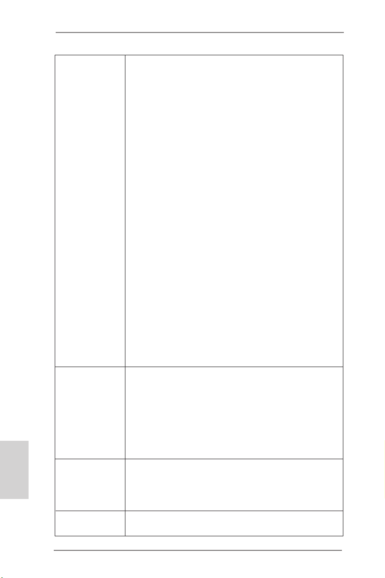
2.1 Installing the CPU
In order to provide the LGA 1155 CPU
sockets more protection and make the
installation process easier, ASRock
has added a new protection cover on
top of the load plate to replace the
former PnP caps that were under the
load plate. For the installation of Intel®
1155-Pin CPUs with the new protection
cover, please follow the steps below.
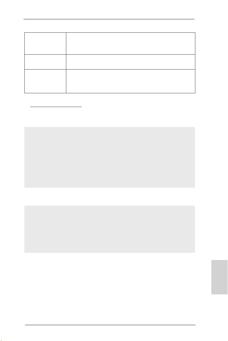
Before you insert the 1155-Pin CPU into the socket, please
check if the CPU surface is unclean or if there are any bent
pins in the socket. Do not force to insert the CPU into the
socket if above situation is found. Otherwise, the CPU will be
seriously damaged.
Step 1. Open the socket:
Step 1-1. Disengage the lever by pressing
it down and sliding it out of the
hook. You do not have to remove
the protection cover.
1155-Pin Socket Overview
English
18
Step 1-2. Keep the lever positioned at
about 135 degrees in order to ip
up the load plate.
Step 2. Insert the 1155-Pin CPU:
Step 2-1. Hold the CPU by the edge which
is marked with a black line.
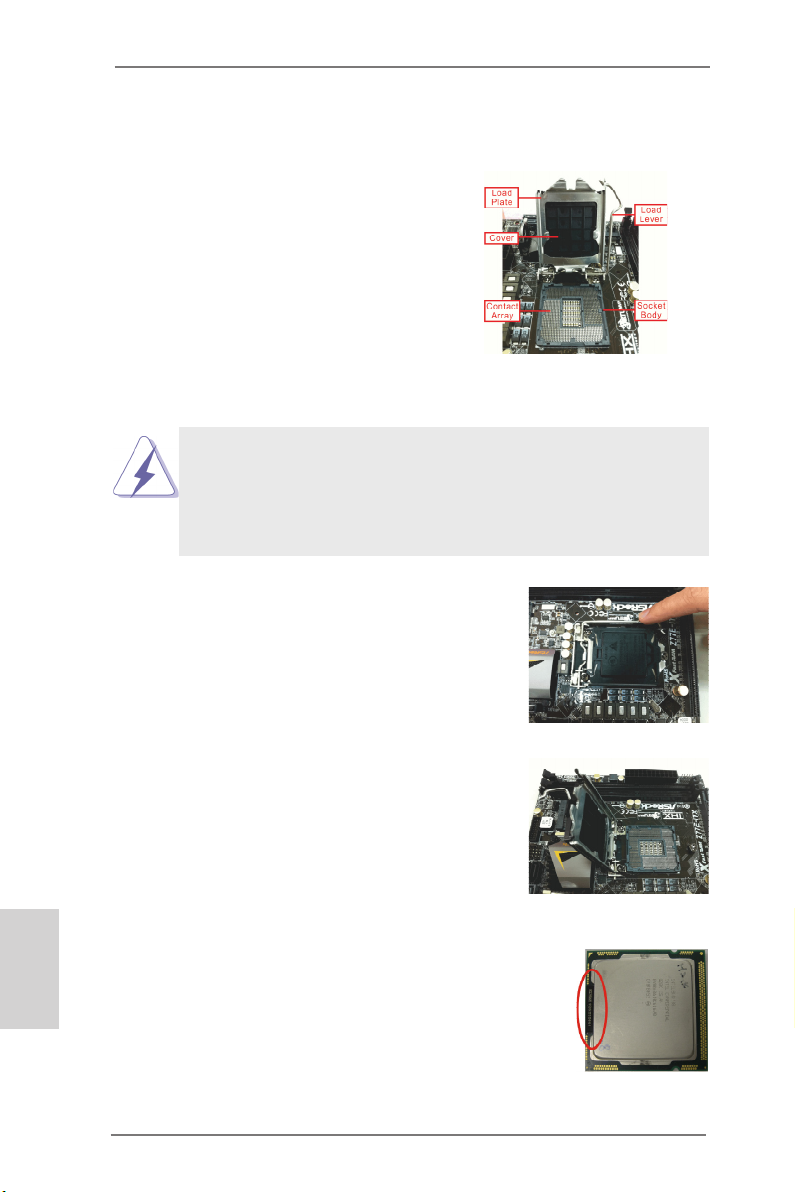
Step 2-2. Orient the CPU with the Integrat-
ed Heat Sink up. Locate Pin1 and
the two orientation key notches.
ASRock Z77 Extreme11 Motherboard
black line
Page 19
orientation key notch
Pin1
orientation key notch
1155-Pin CPU
For proper installation, please ensure to match the two
orientation key notches of the CPU with the two alignment
keys of the socket.
alignment key
alignment key
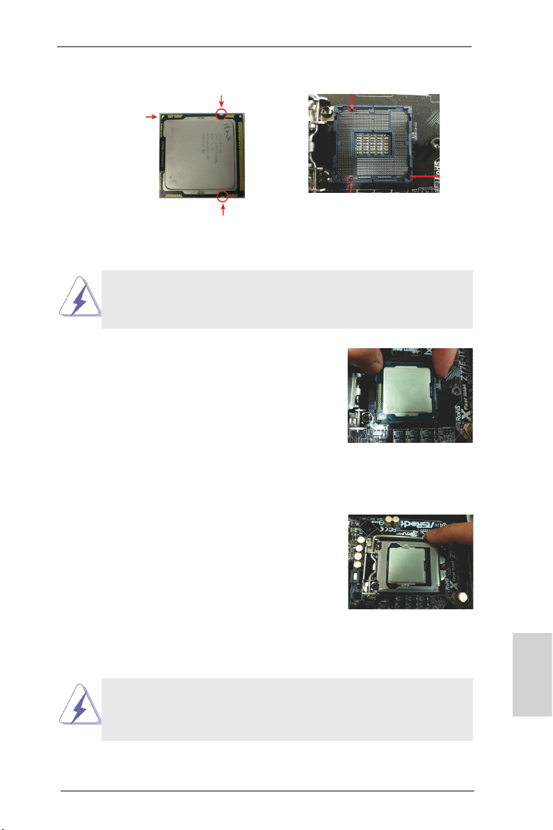
Step 2-3. Carefully place the CPU into the
socket.
Step 2-4. Verify that the CPU is within the
socket and properly mated to the
orient keys.
Pin1
1155-Pin Socket
Step 3. Close the socket:
Step 3-1. Flip the load plate onto the IHS.
Step 3-2. Press down the load lever, and
secure it with the load plate tab
under the retention tab. The protection cover will automatically
come off by itself.
Please save and replace the cover if the processor is removed. The cover must be placed if you wish to return the
motherboard for after service.
ASRock Z77 Extreme11 Motherboard
English
19
Page 20
2.2 Installing the CPU Fan and Heatsink
This motherboard is equipped with 1155-Pin socket that supports Intel
1155-Pin CPUs. Please adopt the type of heatsink and cooling fan compliant with Intel 1155-Pin CPU to dissipate heat. Before you install the
heatsink, you need to spray thermal interface material between the CPU
and the heatsink to improve heat dissipation. Ensure that the CPU and the
heatsink are securely fastened and in good contact with each other. Then
connect the CPU fan to the CPU_FAN connector (CPU_FAN1, see p.2,
No. 4 or CPU_FAN2, see p.2, No. 3).
For proper installation, please kindly refer to the instruction manuals
of your CPU fan and heatsink.
Below is an example to illustrate the installation of a heatsink and fan for
1155-Pin CPUs.
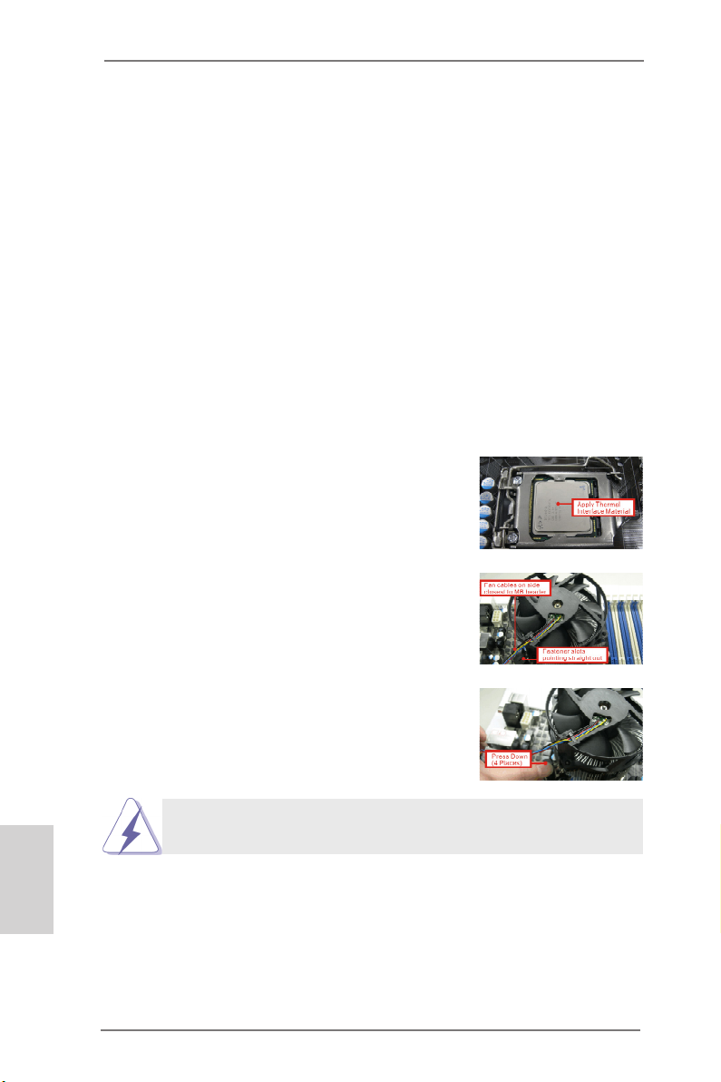
Step 1. Apply thermal interface material onto the
center of the IHS on the socket’s surface.
Step 2. Place the heatsink onto the socket. En-
sure that the fan cables are faced on the
side closest to the CPU fan connector on
the motherboard (CPU_FAN1, see p.2,
No. 4 or CPU_FAN2, see p.2, No. 3).
Step 3. Align the fasteners with the holes on the
motherboard.
Step 4. Rotate the fastener clockwise, then
press the fastener caps down with your
thumb to install and lock. Repeat with the
remaining fasteners.
English
20
If you press down the fasteners without rotating them clockwise, the heatsink cannot be secured on the motherboard.
Step 5. Connect the CPU fan connector with the fan header on the
motherboard.
Step 6. Secure redundant cable with tie-wrap to ensure that the cable
does not interfere with the fan’s operation or contact other
components.
ASRock Z77 Extreme11 Motherboard
Page 21
2.3 Installing Memory Modules (DIMM)
This motherboard provides four 240-pin DDR3 (Double Data Rate 3) DIMM
slots, and supports Dual Channel Memory Technology. For dual channel
conguration, you always need to install identical (the same brand, speed,
size and chip-type) DDR3 DIMM pairs.
1. It is unable to activate Dual Channel Memory Technology
with only one memory module installed.
2. It is not allowed to install a DDR or DDR2 memory module
into a DDR3 slot; otherwise, this motherboard and DIMM
may be damaged.
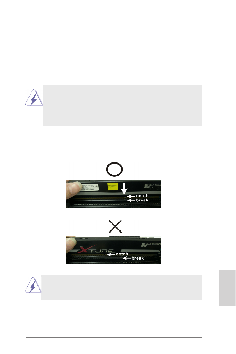
Step 1. Unlock a DIMM slot by pressing the retaining clips outward.
Step 2. Align a DIMM on the slot such that the notch on the DIMM
matches the break on the slot.
The DIMM only ts in one correct orientation. It will cause permanent damage to the motherboard and the DIMM if you force
the DIMM into the slot at incorrect orientation.
Step 3. Firmly insert the DIMM into the slot until the retaining clips at both
ends fully snap back in place and the DIMM is properly seated.
ASRock Z77 Extreme11 Motherboard
English
21
Page 22
2.4 Expansion Slots (PCI Express Slots)
There are 7 PCI Express slots and 1 mini_PCI Express slot on this motherboard.
Mini-PCIE Slots: MINI_PCIE1 is used for mini-PCIE cards.
PCIE slots: PCIE2, PCIE4 and PCIE6 (PCIE 2.0 x1 slots) are used for
PCI Express x1 lane width cards, such as a Gigabit LAN card or
SATA2 cards, etc.
PCIE1 (PCIE 3.0 x16 slot) is used for PCI Express x16 lane
width graphics cards.
PCIE3 and PCIE5 (PCIE 3.0 x16 slot) are used for PCI Express
x8 lane width graphics cards, or used to install PCI Express
graphics cards to support CrossFireXTM or SLITM.
PCIE7 (PCIE 2.0 x16 slot) is used for PCI Express x4 lane width
graphics cards.
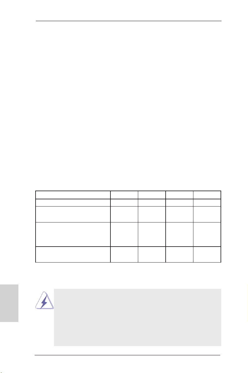
PCIE Slot Congurations
PCIE1 PCIE3 PCIE5 PCIE7
Single Graphics Card x16 N/A N/A N/A
Two Graphics Cards in
CrossFireXTM or SLITM Mode
Three Graphics Cards in
3-Way CrossFireXTM or
3-Way SLITM Mode
Four Graphics Cards in
4-Way CrossFireX
TM
x8 N/A x8 N/A
x8 x8 x8 N/A
x8 x8 x8 x4
English
22
1. For better thermal environment, please connect a chassis fan to the
motherboard’s chassis fan connector (CHA_FAN1, CHA_FAN2 or
CHA_FAN3) when using multiple graphics cards.
2. Only PCIE1, PCIE3 and PCIE5 slots support Gen 3 speed. To run
PCI Express in Gen 3 speed, please install an Ivy Bridge CPU. If you
install a Sandy Bridge CPU, the PCI Express will run only at PCI
Express Gen 2 speed.
ASRock Z77 Extreme11 Motherboard
Page 23

Installing an Expansion Card
Step 1. Before installing an expansion card, please make sure that the
power supply is switched off or the power cord is unplugged.
Please read the documentation of the expansion card and make
necessary hardware settings for the card before you start the
installation.
Step 2. Remove the bracket facing the slot that you intend to use. Keep
the screws for later use.
Step 3. Align the card connector with the slot and press rmly until the
card is completely seated on the slot.
Step 4. Fasten the card to the chassis with screws.
ASRock Z77 Extreme11 Motherboard
English
23
Page 24
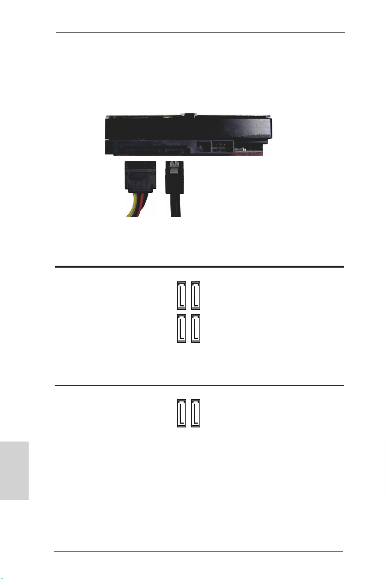
2.5 Installing Serial SATA / SATA2 / SATA3 Hard Disks
STEP 1: Connect the SATA power cable to the hard disk.
STEP 2: Connect one end of the SATA data cable to the hard disk.
STEP 3: Connect the other end of the SATA data cable to the mother-
board’s SAS2 / SATA2 / SATA3 connectors.
English
24
Serial ATA2 Connectors
(SATA2_2_3:
see p.2, No. 14)
(SATA2_4_5:
see p.2, No. 15)
SATA2_3SATA2_5
These four Serial ATA2
(SATA2) connectors sup-
SATA2_2SATA2_4
port SATA data cables for
internal storage devices.
The current SATA2 interface
allows up to 3.0 Gb/s data
transfer rate.
Serial ATA3 Connectors
(SATA3_0_1:
see p.2, No. 13)
SATA3_1
SATA3_0
These two Serial ATA3 (SATA3) connector supports SATA data cables for
internal storage devices. The current SATA3 interface allows up to 6.0 Gb/
s data transfer rate. If the eSATA3 port on the rear I/O has been connected, the internal SATA3_1 will not function.
ASRock Z77 Extreme11 Motherboard
Page 25
SAS2/Serial ATA3
Connectors
(SAS_0_1:
see p.2, No. 16)
(SAS_2_3:
see p.2, No. 17)
(SAS_4_5:
see p.2, No. 18)
(SAS_6_7:
see p.2, No. 19)
SAS_1SAS_5 SAS_3SAS_7
These eight SAS2/Serial
ATA3 (SATA3) connectors
SAS_0SAS_4 SAS_2SAS_6
support SAS/SATA data
cables for internal storage
devices. The current SAS2/
SATA3 interface allows up to
6.0 Gb/s data transfer rate.
We recommend using Intel®
Z77 SATA2 ports instead of
SAS ports for your ODDs.
For connecting SAS HDDs,
please contact SAS data
cable dealers.
ASRock Z77 Extreme11 Motherboard
English
25
Page 26
2.6 Power Connectors
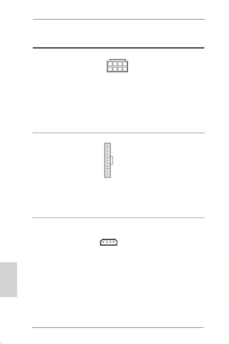
ATX 12V Power Connector
(8-pin ATX12V1)
(see p.2, No. 1)
ATX Power Connector
(24-pin ATXPWR1)
(see p.2, No. 8)
8 5
4 1
12 124
Though this motherboard
provides 8-pin ATX 12V
power connector, it can still
work if you adopt a traditional 4-pin ATX 12V power
supply. To use the 4-pin ATX
power supply, please plug
your power supply along
with Pin 1 and Pin 5.
Though this motherboard
provides a 24-pin ATX
power connector, it can still
work if you adopt a tradi-
13
tional 20-pin ATX power
supply. To use a 20-pin ATX
power supply, please plug
your power supply along Pin
1 and Pin 13.
English
26
SLI/XFIRE Power Connector
(4-pin SLI/XFIRE_PWR1)
(see p.2, No. 48)
SLI/XFIRE_PWR1
ASRock Z77 Extreme11 Motherboard
It is not necessary to use
this connector, but please
connect it with a hard disk
power connector when two
graphics cards are plugged
to this motherboard.
Page 27
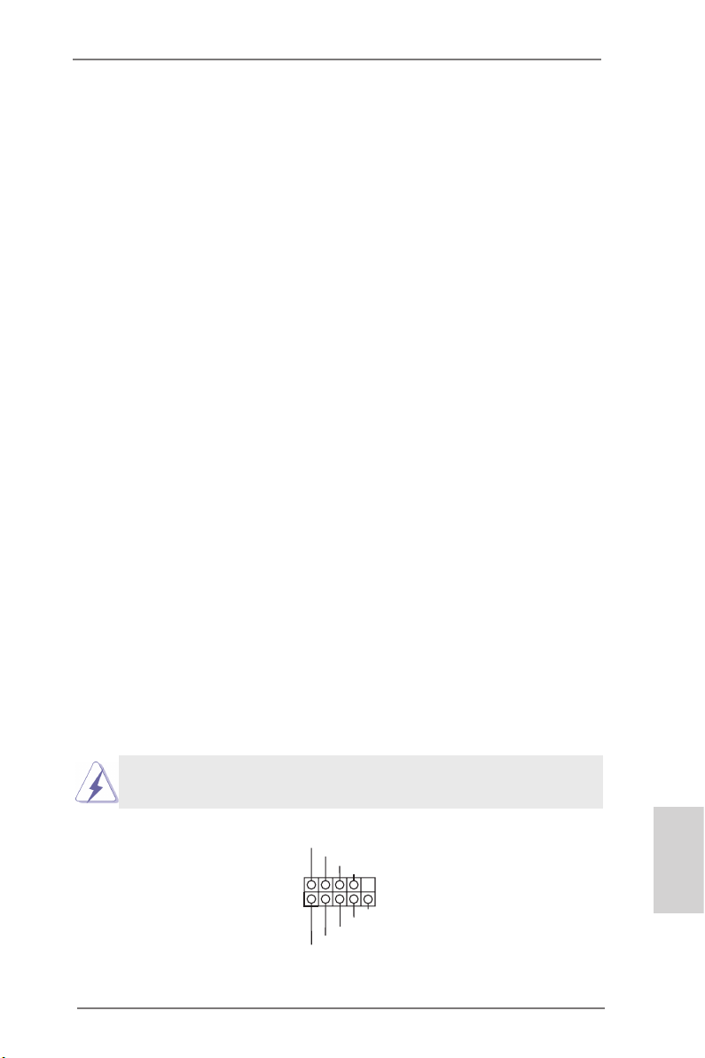
2.7 Installing the System Panel
Connect the power switch, reset switch and system status indicator on the
chassis to this header according to the pin assignments below. Note the
positive and negative pins before connecting the cables.
PWRBTN (Power Switch):
Connect to the power switch on the chassis front panel. You may congure
the way to turn off your system using the power switch.
RESET (Reset Switch):
Connect to the reset switch on the chassis front panel. Press the reset
switch to restart the computer if the computer freezes and fails to perform
a normal restart.
PLED (System Power LED):
Connect to the power status indicator on the chassis front panel. The LED
is on when the system is operating. The LED keeps blinking when the system is in S1/S3 sleep state. The LED is off when the system is in S4 sleep
state or powered off (S5).
HDLED (Hard Drive Activity LED):
Connect to the hard drive activity LED on the chassis front panel. The LED
is on when the hard drive is reading or writing data.
The front panel design may differ by chassis. A front panel module mainly
consists of power switch, reset switch, power LED, hard drive activity LED,
speaker and etc. When connecting your chassis front panel module to
this header, make sure the wire assignments and the pin assignments are
matched correctly.
The white wires are negative (Connect to - or GND pins),
while the colored ones are positive.
1
PLED+
PLED-
HDLED-
HDLED+
PWRBTN#
GND
RESET#
GND
GND
System Panel Header
(9-pin PANEL1)
(see p.2, No. 20)
ASRock Z77 Extreme11 Motherboard
English
27
Page 28
2.8 Onboard Headers and Connectors
Onboard headers and connectors are NOT jumpers. Do NOT
place jumper caps over these headers and connectors. Placing jumper caps over the headers and connectors will cause
permanent damage to the motherboard!
English
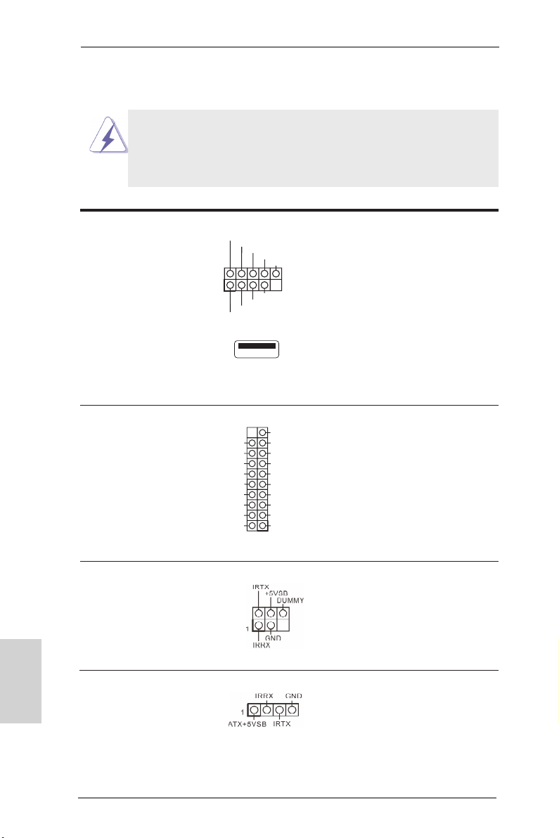
USB 2.0 Headers
(9-pin USB2_3)
(see p.2, No. 29)
(9-pin USB4_5)
(see p.2, No. 30)
(9-pin USB6_7)
(see p.2, No. 31)
(USB8)
(see p.2, No. 28)
USB 3.0 Headers
(19-pin USB3_11_12)
(see p.2, No. 9)
(19-pin USB3_9_10)
(see p.2, No. 10)
IntA_PA_SSRX-
IntA_PA_SSRX+
IntA_PA_SSTX-
IntA_PA_SSTX+
Infrared Module Header
(5-pin IR1)
(see p.2, No. 37)
USB_PWR
1
USB_PWR
Vbus
GND
GND
IntA_PA_D-
IntA_PA_D+
-B
-A
+B
GND
GND
+A
1
DUMMY
VbusVbus
IntA_PB_SSRX-
IntA_PB_SSRX+
GND
IntA_PB_SSTX-
IntA_PB_SSTX+
GND
IntA_PB_D-
IntA_PB_D+
Dummy
Besides two default USB 2.0
ports on the I/O panel, there
are three USB 2.0 headers
and one USB port on this
motherboard. Each USB
2.0 header can support two
USB 2.0 ports.
Besides eight default USB
3.0 ports on the I/O panel,
there are two USB 3.0
header on this motherboard.
Each USB 3.0 header can
support two USB 2.0 ports.
This header supports
an optional wireless
transmitting and receiving
infrared module.
Consumer Infrared
Module Header
(4-pin CIR1)
(see p.2, No. 32)
28
This header can be used
to connect the remote
controller receiver.
ASRock Z77 Extreme11 Motherboard
Page 29
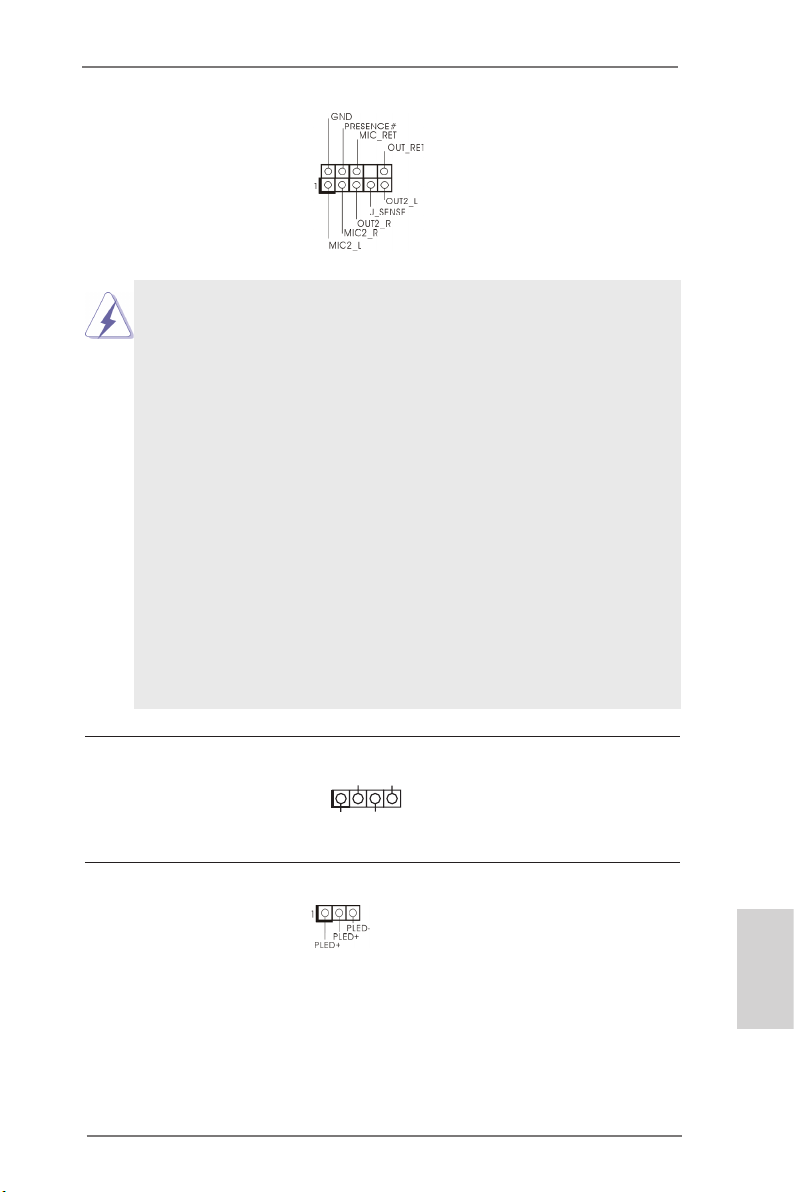
Front Panel Audio Header
(9-pin HD_AUDIO1)
(see p.2, No. 38)
1. High Denition Audio supports Jack Sensing, but the panel wire on
the chassis must support HDA to function correctly. Please follow
the instructions in our manual and chassis manual to install your
system.
2. If you use an AC’97 audio panel, please install it to the front panel
audio header by the steps below:
A. Connect Mic_IN (MIC) to MIC2_L.
B. Connect Audio_R (RIN) to OUT2_R and Audio_L (LIN) to
OUT2_L.
C. Connect Ground (GND) to Ground (GND).
D. MIC_RET and OUT_RET are for HD audio panel only. You don’t
need to connect them for AC’97 audio panel.
E. To activate the front mic.
For Windows® 8 / 8 64-bit / 7 / 7 64-bit / VistaTM / VistaTM
64-bit OS:
Go to the “FrontMic” Tab in the Realtek Control panel. Adjust
“Recording Volume”.
This is an interface for the
front panel audio cable that
allows convenient connection and control of audio
devices.
Chassis Speaker Header
(4-pin SPEAKER1)
(see p.2, No. 23)
Power LED Header
(3-pin PLED1)
(see p.2, No. 22)
ASRock Z77 Extreme11 Motherboard
DUMMY
1
+5V
SPEAKER
DUMMY
Please connect the chassis
speaker to this header.
Please connect the chassis
power LED to this header
to
indicate system power
status. The LED is on when
the system is operating. The
LED keeps blinking in S1/S3
state. The LED is off in S4
state or S5 state (power off).
English
29
Page 30
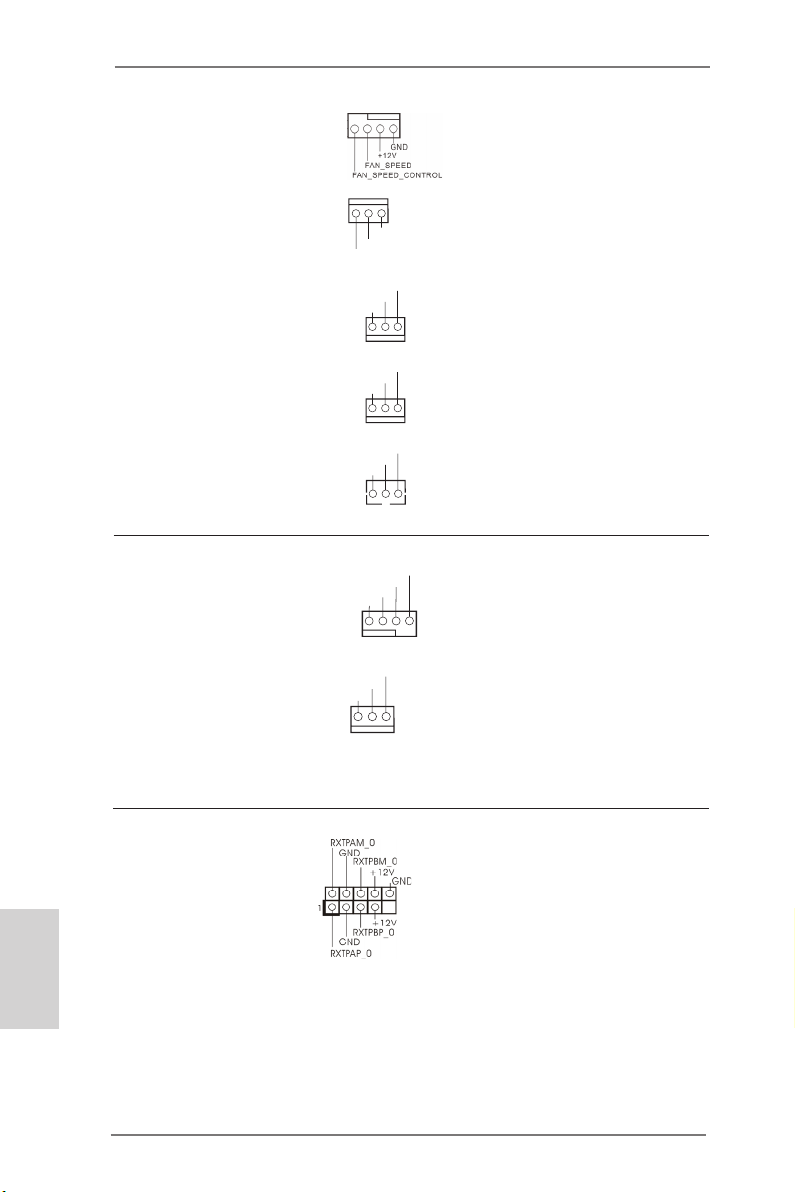
Chassis, Power and SB
GND
+12V
FAN_SPEED
GND
+12V
FAN_SPEED
GND
+12V
FAN_SPEED
GND
+12V
FAN_SPEED
GND
+12V
FAN_SPEED
FAN_SPEED
FAN_SPEED_CONTROL
GND
+12V
1234
Fan Connectors
(4-pin CHA_FAN1)
(see p.2, No. 34)
(3-pin CHA_FAN2)
(see p.2, No. 33)
(3-pin CHA_FAN3)
(see p.2, No. 49)
(3-pin PWR_FAN1)
(see p.2, No. 7)
(3-pin SB_FAN1)
(see p.2, No. 11)
Please connect fan cables
to the fan connectors and
match the black wire to the
ground pin.
English
30
CPU Fan Connectors
(4-pin CPU_FAN1)
(see p.2, No. 4)
(3-pin CPU_FAN2)
(see p.2, No. 3)
IEEE 1394 Header
(9-pin FRONT_1394)
(see p.2, No. 35)
Though this motherboard
provides a 4-Pin CPU fan
(Quiet Fan) connector, 3-Pin
CPU fans can still work successfully even without fan
speed control. If you plan to
connect a 3-Pin CPU fan,
please connect it to Pin 1-3.
Besides one default IEEE
1394 port on the I/O panel,
there is
header on this motherboard.
This IEEE 1394 header can
support one IEEE 1394 port.
ASRock Z77 Extreme11 Motherboard
one IEEE 1394
Page 31

Serial Port Header
(9-pin COM1)
(see p.2, No. 36)
1
RRXD1
DDTR#1
TTXD1
DDCD#1
DDSR#1
CCTS#1
RRTS#1
GND
This COM1 header supports
a serial port module.
RRI#1
HDMI_SPDIF Header
(2-pin HDMI_SPDIF1)
(see p.2, No. 39)
This header provides SPDIF
audio output to HDMI VGA
cards, allowing the system
to connect HDMI Digital
TV/projector/LCD devices.
Please connect the HDMI_
SPDIF connector of a HDMI
VGA card to this header.
ASRock Z77 Extreme11 Motherboard
English
31
Page 32

2.9 Jumpers Setup
The illustration shows how jumpers are
setup. When the jumper cap is placed
on the pins, the jumper is “Short”. If
no jumper cap is placed on the pins,
the jumper is “Open”. The illustration
shows a 3-pin jumper whose pin1 and
pin2 are “Short” when a jumper cap is
placed on these 2 pins.
Clear CMOS Jumper
(CLRCMOS1)
(see p.2, No. 24)
CLRCMOS1 allows you to clear the data in CMOS. To clear and reset
the system parameters to default setup, please turn off the computer and
unplug the power cord from the power supply. After waiting for 15 seconds,
use a jumper cap to short pin2 and pin3 on CLRCMOS1 for 5 seconds.
However, please do not clear the CMOS right after you update the BIOS.
If you need to clear the CMOS when you just nish updating the BIOS,
you must boot up the system rst, and then shut it down before you do the
clear-CMOS action. Please be noted that the password, date, time, user
default prole, 1394 GUID and MAC address will be cleared only if the
CMOS battery is removed.
Clear CMOSDefault
English
32
The Clear CMOS Switch has the same function as the Clear CMOS
jumper.
ASRock Z77 Extreme11 Motherboard
Page 33

2.10 WiFi + BT Module and ASRock Wi-SB Box
WiFi + BT Module
This motherboard comes with an exclusive WiFi 802.11 a/b/g/n + BT v4.0
module that offers support for WiFi 802.11 a/b/g/n connectivity standards
and Bluetooth v4.0. WiFi + BT module is an easy-to-use wireless local
area network (WLAN) adapter to support WiFi + BT. Bluetooth v4.0 standard features Smart Ready technology that adds a whole new class of
functionality into the mobile devices including Apple’s most recent iPhone
4S. BT 4.0 also includes Low Energy Technology and ensures extraordinary low power consumption for PCs. The 2T2R WiFi solution sets a WiFi
high speed standard and offers max link rate up to 300Mbps. Compared to
other 1T1R WiFi motherboards with 150Mbps, ASRock’s 2T2R WiFi solution drives up to 2X faster.
* The transmission speed may vary according to the environment.
* The WiFi + BT module is supported under Windows® 8 / 8 64-bit / 7 / 7 64-bit only.
WiFi + BT Module
ASRock Z77 Extreme11 Motherboard
English
33
Page 34

ASRock Wi-SB Box
Thanks to the excellent placement of antennas, ASRock Wi-SB Box comes with
two invisible antennas (placed in a vertical/horizontal position), hidden inside the
front panel that provides the most stable and unrestricted-direction wireless network
coverage, optimized for maximum broadband network. Additionally, it provides two
Front USB 3.0 ports for easier USB 3.0 device access and 1 rack for SSD placement.
ASRock Wi-SB Box
English
34
ASRock Z77 Extreme11 Motherboard
Page 35

Installing the WiFi + BT Module and ASRock Wi-SB Box
Step 1. Prepare the bundled ASRock Wi-SB Box and screws.
Step 2. If you have 2.5” HDD/SSDs, you may insert up to two and secure them in
ASRock Wi-SB Box with screws.
Step 3. Install ASRock Wi-SB Box into the drive bay of the chassis.
ASRock Z77 Extreme11 Motherboard
English
35
Page 36

Step 4. Screw ASRock Wi-SB Box to the drive bay with screws.
Step 5. Attach the cords to the WiFi + BT module on your motherboard.
Step 6. Plug the Front USB 3.0 cable into the USB 3.0 header on the mother-
board.
English
36
ASRock Z77 Extreme11 Motherboard
Page 37

2.11 Operating System Setup
This motherboard supports various Microsoft® Windows® operating systems: 8 / 8 64-bit / 7 / 7 64-bit / VistaTM / Vista
TM
64-bit. Because motherboard settings and hardware options vary, use the setup procedures in this
chapter for general reference only. Refer your OS documentation for more
information.
ASRock Z77 Extreme11 Motherboard
English
37
Page 38

2.11.1 Installing Windows® 8 / 8 64-bit / 7 / 7 64-bit / VistaTM /
VistaTM 64-bit without RAID
Using AHCI Mode
STEP 1: Set Up UEFI.
Press <F2> or <Delete> at system POST. Set AHCI Mode in UEFI Setup
Utility > Advanced > Storage Conguration > SATA Mode.
STEP 2: Install Windows® 8 / 8 64-bit / 7 / 7 64-bit / VistaTM / VistaTM 64-
bit on your system.
Using IDE Mode
STEP 1: Set Up UEFI.
Press <F2> or <Delete> at system POST. Set IDE Mode in UEFI Setup
Utility > Advanced > Storage Conguration > SATA Mode.
STEP 2: Install Windows® 8 / 8 64-bit / 7 / 7 64-bit / VistaTM / VistaTM 64-
bit on your system.
English
38
ASRock Z77 Extreme11 Motherboard
Page 39

2.11.2 Installing Windows® 8 64-bit / 7 64-bit / VistaTM 64-bit on
a HDD Larger than 2 terabytes (2TB) without RAID
This motherboard adopts UEFI BIOS that allows Windows® OS to be
installed on a large size HDD (>2TB). Please make sure to use Windows®
VistaTM 64-bit (with SP2 or above), 7 64-bit or 8 64-bit and follow the
procedures below to install the operating system.
Using AHCI Mode
STEP 1: Set Up UEFI.
Press <F2> or <Delete> at system POST. Set AHCI Mode in UEFI Setup
Utility > Advanced > Storage Conguration > SATA Mode.
STEP 2: Press <F11> to launch boot menu at system POST and choose
the item “UEFI:<Optical disk drive>“ to boot.
STEP 3: Start Windows® installation.
ASRock Z77 Extreme11 Motherboard
English
39
Page 40

2.11.3 Installing Windows® 8 / 8 64-bit / 7 / 7 64-bit / VistaTM /
VistaTM 64-bit with RAID
STEP 1: Set Up UEFI.
Press <F2> or <Delete> at system POST. Set RAID Mode in UEFI Setup
Utility > Advanced > Storage Conguration > SATA Mode.
STEP 2: Use “RAID Installation Guide” to set the RAID conguration.
Before you start to configure RAID, you need to check the installation
guide in the Support CD for proper configuration. Please refer to the
document in the Support CD, “Guide to SATA Hard Disks Installation and
RAID Conguration”, which is located in the folder at the following path:
.. \ RAID Installation Guide
STEP 3: Install Windows® 8 / 8 64-bit / 7 / 7 64-bit / VistaTM / VistaTM 64-
bit on your system.
English
40
ASRock Z77 Extreme11 Motherboard
Page 41

2.12 Installing Drivers
The Support CD that comes with the motherboard contains necessary drivers and useful utilities that enhance the motherboard’s features.
2.12.1 Running The Support CD
To begin using the support CD, insert the CD into your CD-ROM
drive. The CD automatically displays the Main Menu if “AUTORUN”
is enabled in your computer. If the Main Menu does not appear auto-
matically, locate and double click on the le “ASRSETUP.EXE” in the
Support CD to display the menu.
2.12.2 Drivers Menu
The drivers compatible to your system will be auto-detected and listed on the support CD driver page. Please follow the order from top
to bottom to install those required drivers. Therefore, the drivers you
install can work properly.
2.12.3 Utilities Menu
The Utilities Menu shows the application softwares that the mother-
board supports. Click on a specic item then follow the installation
wizard to install it.
2.12.4 Contact Information
If you need to contact ASRock or want to know more about ASRock,
you’re welcome to visit ASRock’s website at http://www.asrock.com;
or you may contact your dealer for further information.
ASRock Z77 Extreme11 Motherboard
English
41
Page 42

2.13 Smart Switches
The motherboard has three smart switches: Power Switch, Reset Switch
and Clear CMOS Switch, allowing users to quickly turn on/off the system,
reset the system or clear the CMOS values.
Power Switch
(PWRBTN)
(see p.2, No. 25)
Reset Switch
(RSTBTN)
(see p.2, No. 26)
Clear CMOS Switch
(CLRCBTN)
(see p.4, No. 17)
Power
Reset
Power Switch allows users
to quickly turn on/off the
system.
Reset Switch allows users
to quickly reset the system.
Clear CMOS Switch allows
users to quickly clear the
CMOS values.
English
42
ASRock Z77 Extreme11 Motherboard
Page 43

2.14 Dr. Debug
Dr. Debug is used to provide code information, which makes
troubleshooting even easier. Please see the diagrams below for reading
the Dr. Debug codes.
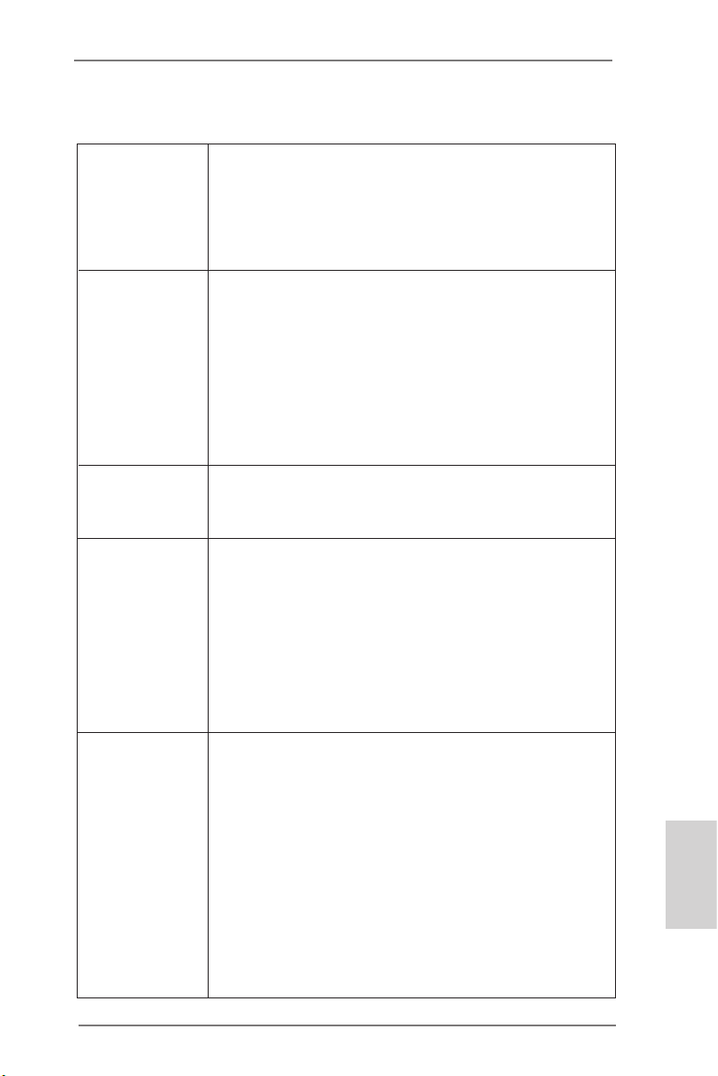
Code Description
00 Please check if the CPU is installed correctly and then clear
CMOS.
0d Problem related to memory, VGA card or other devices.
Please clear CMOS, re-install the memory and VGA card,
and remove other USB, PCI devices.
01 - 54 Problem related to memory. Please re-install the CPU and
(except 0d), memory then clear CMOS. If the problem still exists, please
5A- 60 install only one memory module or try using other memory
modules.
55 The Memory could not be detected. Please re-install the
memory and CPU. If the problem still exists, please install
only one memory module or try using other memory
modules.
61 - 91 Chipset initialization error. Please press reset or clear
CMOS.
92 - 99 Problem related to PCI-E devices. Please re-install PCI-E
devices or try installing them in other slots. If the problem
still exists, please remove all PCI-E devices or try using
another VGA card.
A0 - A7 Problem related to IDE or SATA devices. Please re-install
IDE and SATA devices. If the problem still exists, please
clear CMOS and try removing all SATA devices.
b0 Problem related to memory. Please re-install the CPU and
memory. If the problem still exists, please install only one
memory module or try using other memory modules.
* For X79 models, please try installing memory to DDR3 A1,
B1, C1 and D1 slots.
b4 Problem related to USB devices. Please try removing all
USB devices.
English
ASRock Z77 Extreme11 Motherboard
43
Page 44

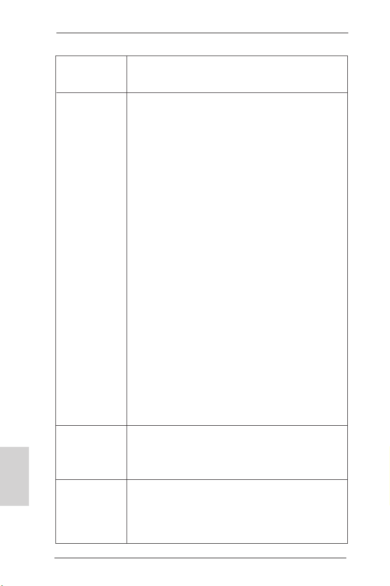
b7 Problem related to memory. Please re-install the CPU and
memory then clear CMOS. If the problem still exists, please
install only one memory module or try using other memory
modules.
d6 The VGA could not be recognized. Please clear CMOS and
try re-installing the VGA card. If the problem still exists,
please try installing the VGA card in other slots or use other
VGA cards.
d7 The Keyboard and mouse could not be recognized. Please
try re-installing the keyboard and mouse.
d8 Invalid Password.
FF Please check if the CPU is installed correctly and then clear
CMOS.
English
44
ASRock Z77 Extreme11 Motherboard
Page 45

2.15 SLITM, 3-Way SLITM and Quad SLITM Operation Guide
This motherboard supports NVIDIA® SLITM, 3-Way SLITM and Quad SLITM
(Scalable Link Interface) technology that allows you to install up to three
identical PCI Express x16 graphics cards. Currently, NVIDIA® SLITM, 3-Way
SLITM and Quad SLITM technology supports Windows® VistaTM / VistaTM 64bit / 7 / 7 64-bit / 8 / 8 64-bit OS.
Requirements
1. You should only use identical SLITM-ready graphics cards that are
NVIDIA® certied.
2. Make sure that your graphics card driver supports NVIDIA® SLITM
technology. Download the drivers from the NVIDIA® website:
www.nvidia.com
3. Make sure that your power supply unit (PSU) can provide at least the
minimum power your system requires. It is recommended to use a
NVIDIA® certied PSU. Please refer to the NVIDIA® website for details.
2.15.1 Installing Two SLITM-Ready Graphics Cards
Step 1. Insert one graphics card into PCIE1 slot and the other graphics
card to PCIE5 slot. Make sure that the cards are properly seated
on the slots.
Step 2. If required, connect the auxiliary power source to the PCI Express
graphics cards.
ASRock Z77 Extreme11 Motherboard
English
45
Page 46

English
Step 3. Align and insert the ASRock SLI_Bridge_3S Card to the gold-
fingers on each graphics card. Make sure the ASRock SLI_
Bridge_3S Card is rmly in place.
ASRock SLI_Bridge_3S Card
Step 4. Connect a VGA cable or a DVI cable to the monitor connector or
the DVI connector of the graphics card that is inserted to PCIE1
slot.
2.15.2 Installing Three SLITM-Ready Graphics Cards
Step 1. Each graphics card should have two goldngers for the 3-Way SLI
Bridge connector. Insert one graphics card into PCIE1 slot, another graphics card to PCIE3 slot, and the other graphics card to
PCIE5 slot. Make sure that the cards are properly seated on the
slots.
46
Two Goldngers
ASRock Z77 Extreme11 Motherboard
Page 47

Step 2. Connect the auxiliary power source to the PCI Express graphics
card. Please make sure that both power connectors on the PCI
Express graphics card are connected. Repeat this step on the
three graphics cards.
Step 3. Align and insert the ASRock 3-Way SLI Bridge Card to the gold-
ngers on each graphics card. Make sure the ASRock 3-Way SLI
Bridge Card is rmly in place.
ASRock 3-Way SLI
Bridge Card
Step 4. Connect a VGA cable or a DVI cable to the monitor connector or
the DVI connector of the graphics card that is inserted to PCIE1
slot.
ASRock Z77 Extreme11 Motherboard
English
47
Page 48

2.15.3 Driver Installation and Setup
Install the graphics card drivers to your system. After that, you can enable
the Multi-Graphics Processing Unit (GPU) in the NVIDIA® nView system
tray utility. Please follow the below procedures to enable the multi-GPU.
For SLITM and Quad SLITM mode
English
B. From the pop-up menu, select All Programs, and then click
NVIDIA Corporation.
C. Select NVIDIA Control Panel tab.
D. Select Control Panel tab.
E. From the pop-up menu, select Set SLI and PhysX
conguration. In Set PhysX GPU acceleration item, please
select Enabled.
F. In Select an SLI conguration item, please select Enable
SLI. And click Apply.
A. Click the Start icon on your Windows taskbar.
48
ASRock Z77 Extreme11 Motherboard
Page 49

G. Reboot your system.
H. You can freely enjoy the benets of SLITM or Quad SLITM.
For 3-Way SLITM mode
A. Follow steps A to E on the previous page.
B. In Select an SLI conguration item, please select Enable
3-way SLI and click Apply.
C. Reboot your system.
D. You can freely enjoy the benets of 3-Way SLITM.
* SLITM appearing here is a registered trademark of NVIDIA® Technologies Inc., and
is used only for identication or explanation and to the owners’ benet, without
intent to infringe.
ASRock Z77 Extreme11 Motherboard
English
49
Page 50

2.16 CrossFireXTM, 3-Way CrossFireXTM, 4-Way CrossFireXTM
and Quad CrossFireXTM Operation Guide
This motherboard supports CrossFireXTM, 3-way CrossFireXTM, 4-way
CrossFireXTM and Quad CrossFireXTM that allows you to install up to four
identical PCI Express x16 graphics cards. Currently CrossFireXTM, 3-way
CrossFireXTM, 4-way CrossFireXTM and Quad CrossFireXTM are supported
with Windows® VistaTM / VistaTM 64-bit / 7 / 7 64-bit / 8 / 8 64-bit OS.
English
are AMD certied.
2. Make sure that your graphics card driver supports AMD CrossFireXTM
technology. Download the drivers from the AMD’s website:
www.amd.com
3. Make sure that your power supply unit (PSU) can provide at least the
minimum power your system requires. It is recommended to use a
AMD certied PSU. Please refer to the AMD’s website for details.
4. If you pair a 12-pipe CrossFireXTM Edition card with a 16-pipe card,
both cards will operate as 12-pipe cards while in CrossFireXTM mode.
5. Different CrossFireXTM cards may require different methods to enable
CrossFireXTM. Please refer to AMD graphics card manuals for detailed
installation guide.
1. You should only use identical CrossFireXTM-ready graphics cards that
2.16.1 Installing Two CrossFireXTM-Ready Graphics Cards
Step 1. Insert one graphics card into PCIE1 slot and the other graphics
card to PCIE5 slot. Make sure that the cards are properly seated
on the slots.
50
ASRock Z77 Extreme11 Motherboard
Page 51

Step 2. Connect two graphics cards by installing a CrossFire Bridge on
the CrossFire Bridge Interconnects on the top of the graphics
cards. (The CrossFire Bridge is provided with the graphics card
you purchase, not bundled with this motherboard. Please refer to
your graphics card vendor for details.)
CrossFire Bridge
Step 3. Connect a VGA cable or a DVI cable to the monitor connector or
the DVI connector of the graphics card that is inserted to PCIE1
slot.
ASRock Z77 Extreme11 Motherboard
English
51
Page 52

2.16.2 Installing Three CrossFireXTM-Ready Graphics Cards
Step 1. Insert one graphics card into PCIE1 slot, another graphics card to
PCIE3 slot, and the other graphics card to PCIE5 slot. Make sure
that the cards are properly seated on the slots.
Step 2. Use one CrossFireTM Bridge to connect the graphics cards on
PCIE1 and PCIE3 slots, and use the other CrossFireTM Bridge
to connect the graphics cards on PCIE3 and PCIE5 slots. (The
CrossFireTM Bridge is provided with the graphics card you purchase, not bundled with this motherboard. Please refer to your
graphics card vendor for details.)
English
52
Step 3.
CrossFireTM Bridge
Connect a VGA cable or a DVI cable to the monitor connector or
the DVI connector of the graphics card that is inserted to PCIE1
slot.
ASRock Z77 Extreme11 Motherboard
Page 53

2.16.3 Installing Four CrossFireXTM-Ready Graphics Cards
Step 1. Insert one graphics card into PCIE1 slot, another graphics card
into PCIE3 slot, the third graphics card into PCIE5 slot and the
last graphics card into PCIE7 slot. Make sure that the cards are
properly seated on the slots.
Step 2. Use one CrossFireTM Bridge to connect the graphics cards on
PCIE1 and PCIE3 slots, another CrossFireTM Bridge to connect
the graphics cards on PCIE3 and PCIE5 slots, and use the third
CrossFireTM Bridge to connect the graphics cards on PCIE5 and
PCIE7 slots. (The CrossFireTM Bridge is provided with the graphics card you purchase, not bundled with this motherboard. Please
refer to your graphics card vendor for details.)
CrossFireTM Bridge
Step 3. Connect a VGA cable or a DVI cable to the monitor connector or
the DVI connector of the graphics card that is inserted to PCIE1
slot.
ASRock Z77 Extreme11 Motherboard
English
53
Page 54

2.16.4 Driver Installation and Setup
Step 1. Power on your computer and boot into OS.
Step 2. Remove the AMD drivers if you have any VGA drivers installed in
your system.
The Catalyst Uninstaller is an optional download. We recommend using
this utility to uninstall any previously installed Catalyst drivers prior to in-
stallation. Please check AMD’s website for AMD driver updates.
Step 3. Install the required drivers and CATALYST Control Center then
restart your computer. Please check AMD’s website for details.
Step 4. You will find “AMD Catalyst Control Center” on your Windows®
taskbar.
AMD Catalyst Control Center
Step 5. Double-click “AMD Catalyst Control Center”. Click “View”, select
“CrossFireXTM”, and then check the item “Enable CrossFireXTM”. If
you installed two graphics cards, select “2 GPUs” and click “Apply”.
If you installed three graphics cards, select “3 GPUs” and click
“Apply”. If you installed four graphics cards, select “4 GPUs” and
click “Apply”.
English
54
ASRock Z77 Extreme11 Motherboard
Page 55

2.17 Surround Display
This motherboard supports surround display upgrade. With the internal
VGA output support (HDMI) and external add-on PCI Express VGA cards,
you can easily enjoy surround display.
Please refer to the following steps to set up a surround display environment:
1. Install the VGA cards on the PCIE slots. Please refer to Installing
Memory Modules for details of proper expansion card installation
procedures.
2. Connect monitor cables to the corresponding connectors of the rear I/O
and the add-on PCI Express VGA cards.
3. Install the onboard VGA driver and the add-on PCI Express VGA card
drivers to your system. If you have installed the drivers already, there is
no need to install them again.
4. Set up a multi-monitor display.
For Windows® 8 / 8 64-bit / 7 / 7 64-bit / VistaTM / VistaTM 64-bit OS:
Right click the desktop, choose “Personalize”, and select the
“Display Settings” tab so that you can adjust the parameters of
the multi-monitor according to the steps below.
A. Click the number ”2” icon.
B. Click the items “This is my main monitor” and “Extend the
desktop onto this monitor”.
C. Click “OK” to save your change.
D. Repeat steps A through C for the display icon identied by the
numbers.
6. Use Surround Display. Click and drag the display icons to positions
representing the physical setup of your monitors that you would like to
use. The placement of display icons determines how you move items
from one monitor to another.
ASRock Z77 Extreme11 Motherboard
English
55
Page 56

2.18 Dual LAN and Teaming Operation Guide
Dual LAN with Teaming enabled on this motherboard allows two single
connections to act as one single connection for twice the transmission
bandwidth, making data transmission more effective and improving the
quality of transmission of distant images. Fault tolerance on the dual LAN
network prevents network downtime by transferring the workload from a
failed port to a working port.
The speed of transmission is subject to the actual network environment or
status even with Teaming enabled.
Before setting up Teaming, please make sure whether your Switch (or
Router) supports Teaming (IEEE 802.3ad Link Aggregation). You can
specify a preferred adapter in Intel PROSet. Under normal conditions, the
Primary adapter handles all non-TCP/IP trafc. The Secondary adapter will
receive fallback trafc if the primary fails. If the Preferred Primary adapter
fails, but is later restored to an active status, control is automatically
switched back to the Preferred Primary adapter.
1. From Device Manager, open the properties of a team.
English
56
2. Click the Settings tab.
3. Click the Modify Team button.
4. Select the adapter you want to be the primary adapter and click the Set
Primary button.
If you do not specify a preferred primary adapter, the software will choose
an adapter of the highest capability (model and speed) to act as the default
primary. If a failover occurs, another adapter becomes the primary. The
adapter will, however, rejoin the team as a non-primary.
ASRock Z77 Extreme11 Motherboard
Page 57

3. BIOS Information
The Flash Memory on the motherboard stores the BIOS Setup Utility.
When you start up the computer, please press <F2> or <Del> during the
Power-On-Self-Test (POST) to enter the BIOS Setup utility; otherwise,
POST continues with its test routines. If you wish to enter BIOS Setup after
POST, please restart the system by pressing <Ctl> + <Alt> + <Delete>, or
pressing the reset button on the system chassis. The BIOS Setup program
is designed to be user-friendly. It is a menu-driven program, which allows
you to scroll through its various sub-menus and to select among the predetermined choices. For detailed information about BIOS Setup, please refer
to the User Manual (PDF le) contained in the Support CD.
ASRock Z77 Extreme11 Motherboard
English
57
Page 58

Deutsch
1. Einführung
Wir danken Ihnen für den Kauf des ASRock Z77 Extreme11 Motherboard,
ein zuverlässiges Produkt, welches unter den ständigen, strengen Qualitätskontrollen von ASRock gefertigt wurde. Es bietet Ihnen exzellente
Leistung und robustes Design, gemäß der Verpichtung von ASRock zu
Qualität und Halbarkeit. Diese Schnellinstallationsanleitung führt in das
Motherboard und die schrittweise Installation ein. Details über das Mother-
board nden Sie in der Bedienungsanleitung auf der Support-CD.
Da sich Motherboard-Spezikationen und BIOS-Software verändern können,
kann der Inhalt dieses Handbuches ebenfalls jederzeit geändert werden. Für
den Fall, dass sich Änderungen an diesem Handbuch ergeben, wird eine neue
Version auf der ASRock-Website, ohne weitere Ankündigung, verfügbar sein.
Die neuesten Grakkarten und unterstützten CPUs sind auch auf der ASRock-
Website aufgelistet.
ASRock-Website: http://www.asrock.com
Wenn Sie technische Unterstützung zu Ihrem Motherboard oder spezische
Informationen zu Ihrem Modell benötigen, besuchen Sie bitte unsere Webseite:
www.asrock.com/support/index.asp
1.1 Kartoninhalt
ASRock Z77 Extreme11 Motherboard
(EATX-Formfaktor: 30.5 cm x 26.7 cm; 12.0 Zoll x 10.5 Zoll)
ASRock Z77 Extreme11 Schnellinstallationsanleitung
ASRock Z77 Extreme11 Support-CD
Acht Serial ATA (SATA) -Datenkabel
Zwei Serial ATA (SATA) -Festplattenstromkabel
Ein I/O Shield
Ein ASRock SLI_Bridge_3S-Karte
Ein ASRock 3-Wege-SLI-Brücke-Karte
Eine ASRock Wi-SB-Box
Zwölf Schrauben
58
ASRock Z77 Extreme11 Motherboard
Page 59

1.2 Spezikationen
Plattform - EATX-Formfaktor: 30.5 cm x 26.7 cm; 12.0 Zoll x
10.5 Zoll
- 56,7g Kupferpaste PCB
- Hochwertiges Gold-Kondensatordesign (100 %
hochwertige japanische Fertigung leitfähiger
Polymerkondensatoren)
CPU - Unterstützt Intel® CoreTM i7- / i5- / i3-Prozessoren der
3ten und 2ten Generation im LGA1155-Package
- Digi Power-Design
- 8 + 4-Stromphasendesign
- Dual-Stack-MOSFET (DSM)
- Unterstützt Intel® Turbo Boost 2.0-Technologie
- Unterstützt freigegebene CPU der K-Serie
- Unterstützt Hyper-Threading-Technologie
Chipsatz - Intel® Z77
- Unterstützt Intel® Rapid Start Technology und Smart
Connect Technology
Speicher - Dual-Kanal DDR3 Speichertechnologie
- 4 x Steckplätze für DDR3
- Unterstützt DDR3 3000+(OC)/2400(OC)/2133(OC)/
1866(OC)/1600/1333/1066 non-ECC, ungepufferter
Speicher
- Max. Kapazität des Systemspeichers: 32GB
- Unterstützt Intel® Extreme Memory Prole (XMP)1.3/
1.2
Erweiterungs- - 3 x PCI Express 3.0 x16 slots (PCIE1/PCIE5: Einzeln
steckplätze bei x16 (PCIE1) / x8 (PCIE5) oder dual im x8/x8
Modus; PCIE3: x8 modus)
* PCIE 3.0 wird nur mit Intel® Ivy Bridge-Prozessor
unterstützt. Mit Intel® Sandy Bridge-Prozessor wird
nur PCIE 2.0 unterstützt.
- 1 x PCI Express 2.0 x16-Steckplatz (PCIE7: x4 Modus)
- 3 x PCI Express 2.0 x1-Steckplätze
- 1 x mini-PCI-Express-Steckplatz: Für WiFi + BT-
Deutsch
Français
ASRock Z77 Extreme11 Motherboard
59
Page 60

Deutsch
Modul
- PLX PEX 8747- und PLX PEX 8608, eingebettet
- Unterstützt AMD Quad CrossFireXTM, 4-Way
CrossFireXTM, 3-Way CrossFireXTM und CrossFireX
- NVIDIA® Quad SLITM, 3-Way SLITM und SLI
TM
TM
Onboard-VGA * Integrierte Intel® HD-Grakdarstellungen und die
VGA-Ausgänge können nur durch GPU-integrierte
Prozessoren unterstützt werden.
- Unterstützt Intel® HD Graphics Built-in Visuals: Intel®
Quick Sync Video 2.0, Intel® InTruTM 3D, Intel® Clear
Video HD-Technologie, Intel® InsideTM, Intel® HD
Graphics 2500/4000 mit Intel® Ivy-Bridge-CPU
- Intel® Quick Sync Video, Intel® InTruTM 3D, Intel®
Clear Video HD-Technologie, Intel® HD Graphics
2000/3000, Intel® Advanced Vector Extensions (AVX)
mit Intel® Sandy-Bridge-CPU
- Pixel Shader 5.0, DirectX 11 mit Intel® Ivy Bridge Prozessor, Pixel Shader 4.1, DirectX 10.1 mit Intel®
Sandy Bridge-Prozessor
- Maximal gemeinsam genutzter Speicher 1760MB mit
Intel® Ivy Bridge-Prozessor. Maximal gemeinsam
genutzter Speicher 1760MB mit Intel® Sandy Bridge Prozessor.
- Unterstützt HDMI 1.4a mit einer maximalen
Auösung von 1920 x 1200 bei 60 Hz
- Unterstützt Auto Lip Sync, Deep Color (12bpc),
xvYCC und HBR (High Bit Rate-Audio) mit HDMI
- Unterstützt HDCP mit HDMI
- Unterstutzt 1080p Blu-ray (BD) / HD-DVD Wiedergabe mit HDMI
Audio - 7.1 CH HD Audio mit dem Inhalt Schutz (Realtek
ALC898 Audio Codec)
- Premium Blu-ray-Audio-Unterstützung
- Unterstützt THX TruStudio
TM
LAN - PCIE x1 Gigabit LAN 10/100/1000 Mb/s
- Intel 82579V, Intel 82583V
- Unterstützt Wake-On-LAN
60
ASRock Z77 Extreme11 Motherboard
Page 61

- Unterstützt Dual-LAN mit Teaming
- Unterstützt PXE
Wireless LAN - Unterstützt IEEE 802.11a/b/g/n
- Unterstützt Dual-Band (2.4/5 GHz)
- Unterstützt High-Speed-WLAN-Verbindung bis 300
Mb/s
- 2 Antennen zur Unterstützung von MIMO Technologie, 2 (senden) x 2 (empfangen)
- Unterstützt Bluetooth 4.0 Klasse 2
E/A-Anschlüsse - 1 x PS/2-Mausanschluss/Tastaturanschluss
an der - 1 x HDMI port
Rückseite - 1 x optischer SPDIF-Ausgang
- 2 x Standard-USB 2.0-Anschlüsse
- 1 x eSATA3-Anschluss
- 8 x Standard-USB 3.0-Anschlüsse
- 2 x RJ-45 LAN Ports mit LED (ACT/LINK LED und
SPEED LED)
- 1 x IEEE 1394 Port
- 1 x CMOS löschen-Schalter
- HD Audiobuchse: Lautsprecher hinten / Mitte / Bass /
Audioeingang / Lautsprecher vorne / Mikrofon
SAS2/SATA3 - 2 x SATA 3-Anschlüsse (6,0 Gb/s) durch Intel® Z77;
unterstützt RAID- (RAID 0, RAID 1, RAID 5, RAID 10,
Intel Rapid Storage und Intel Smart Response Technologie), NCQ-, AHCI-und Hot Plug (SATA3_1
Anschluss wird mit dem eSATA3-Port geteilt)
- 8 x SAS2/SATA3-6-Gb/s-Anschlüsse per LSI
SAS2308 PCIe 3.0-x8-Controller, unterstützt RAID
(RAID 0, RAID 1, RAID 1E und RAID 10), MegaRAID
Utility, NCQ und Hot-Plug
USB3.0 - 4 x USB 3.0-Ports an der Rückseite durch Intel® Z77,
unterstützt USB 1.1/2.0/3.0 mit bis zu 5 Gb/s
- 4 x USB 3.0-Ports an der Rückseite durch Etron
EJ188, unterstützt USB 1.1/2.0/3.0 mit bis zu 5 Gb/s
- 2 x USB 3.0-Header (Unterstützt vier USB 3.0-Ports)
an der Vorderseite durch Etron EJ188, unterstützt
USB 1.1/2.0/3.0 mit bis zu 5 Gb/s
Deutsch
Français
ASRock Z77 Extreme11 Motherboard
61
Page 62

Deutsch
Anschlüsse - 4 x SATA2 3,0 GB/s-Anschlüsse, unterstützen RAID-
(RAID 0, RAID 1, RAID 5, RAID 10, Intel Rapid
Storage und Intel Smart Response-Technologie),
NCQ-, AHCI-und Hot Plug
- 2 x SATA3 6,0 GB/s-Anschlüsse
- 8 x SAS2/SATA3 6,0 GB/s-Anschlüsse
- 1 x Infrarot-Modul-Header
- 1 x Consumer Infrared-Modul-Header
- 1 x COM-Anschluss-Header
- 1 x HDMI_SPDIF-Anschluss
- 1 x IEEE 1394-Anschluss
- 1 x Betriebs-LED-Header
- 2 x CPUlüfter-Anschlüsse (1 x 4-pin, 1 x 3-pin)
- 3 x Gehäuselüfter-Anschlüsse (1 x 4-pin, 2 x 3-pin)
- 1 x Stromlüfter-Anschluss (3-pin)
- 1 x SBlüfter-Anschluss (3-pin)
- 24-pin ATX-Netz-Header
- 8-pin anschluss für 12V-ATX-Netzteil
- SLI/XFIRE-Netz-Header
- Anschluss für Audio auf der Gehäusevorderseite
- 3 x USB 2.0-Anschlüsse (Unterstützung 6
zusätzlicher USB 2.0-Anschlüsse)
- 1 x USB, Typ A, vertikal
- 2 x USB 3.0-Anschlüsse (Unterstützung 4
zusätzlicher USB 3.0-Anschlüsse)
- 1 x Dr. Debug (Debug-LED mit 7 Segmenten)
- 1 x Netzschalter mit LED
- 1 x Rücksetzschalter (Reset) mit LED
BIOS - 64Mb AMIs Legal BIOS UEFI mit GUI-Unterstützung
- Unterstützung für “Plug and Play”
- ACPI 1.1-Weckfunktionen
- JumperFree-Modus
- SMBIOS 2.3.1
- CPU Core, IGPU, DRAM, 1.8V PLL, VTT, VCCSA
Stromspannung Multianpassung
CD d’assistance - Treiber, Dienstprogramme, Antivirussoftware
(Probeversion), CyberLink MediaEspresso 6.5-Test
62
ASRock Z77 Extreme11 Motherboard
Page 63

version, Google Chrome-Browser und
Toolbar
Hardware - Überwachung der CPU/Gehäuse/Strom/SB Monitor Temperatur
- Drehzahlmessung für CPU/Gehäuse/Strom/SB lüfter
- Geräuscharmer CPU-/Gehäuselüfter
- Mehrstu ge Geschwindigkeitssteuerung für CPU/
Gehäuse lüfter
- Spannungsüberwachung: +12V, +5V, +3.3V, Vcore
Betriebssysteme - Unterstützt Microsoft® Windows® 8 / 8 64-bit / 7 / 7
64-Bit / VistaTM / Vista
TM
64-Bit
Zertizierungen - FCC, CE, WHQL
- Gemäß Ökodesign-Richtlinie (ErP/EuP)
(Stromversorgung gemäß Ökodesign-Richtlinie (ErP/
EuP) erforderlich)
* Für die ausführliche Produktinformation, besuchen Sie bitte unsere Website: http://www.asrock.com
WARNUNG
Beachten Sie bitte, dass Overclocking, einschließlich der Einstellung im BIOS, Anwenden der Untied Overclocking-Technologie oder
Verwenden von Overclocking-Werkzeugen von Dritten, mit einem
gewissen Risiko behaftet ist. Overclocking kann sich nachteilig auf
die Stabilität Ihres Systems auswirken oder sogar Komponenten und
Geräte Ihres Systems beschädigen. Es geschieht dann auf eigene
Gefahr und auf Ihre Kosten. Wir übernehmen keine Verantwortung
für mögliche Schäden, die aufgrund von Overclocking verursacht
wurden.
ASRock Z77 Extreme11 Motherboard
63
Deutsch
Français
Page 64

1.3 Integrierte Header und Anschlüsse
Integrierte Header und Anschlüsse sind KEINE Jumper. Setzen
Sie KEINE Jumperkappen auf diese Header und Anschlüsse.
Wenn Sie Jumperkappen auf Header und Anschlüsse setzen,
wird das Motherboard unreparierbar beschädigt!
Deutsch
Seriell-ATA2-Anschlüsse
(SATA2_2_3:
siehe S.2 - No. 14)
(SATA2_4_5:
siehe S.2 - No. 15)
SATA2_3SATA2_5
Diese vier Serial ATA2
(SATA2) Verbínder unter-
SATA2_2SATA2_4
stützten SATA Datenkabel
für interne Massenspeichergeräte. Die aktuelle SATA2- Schnittstelle
ermöglicht eine Datenübertragungsrate bis 3,0 Gb/s.
Seriell-ATA3-Anschlüsse
(SATA3_0_1:
siehe S.2 - No. 13)
SATA3_1
SATA3_0
Diese zwei Serial ATA3 (SATA3) Verbínder unterstützten SATA Datenkabel für interne Massenspeichergeräte. Die aktuelle SATA3- Schnittstelle
ermöglicht eine Datenübertragungsrate bis 6,0 Gb/s. Wenn Sie die Fest-Wenn Sie die Festplatte am eSATA3-Port an der Rückblende anschließen, wird der interne
SATA3_1 Anschluss deaktiviert.
64
ASRock Z77 Extreme11 Motherboard
Page 65

SAS2/Seriell-ATA3Anschlüsse
(SAS_0_1:
siehe S.2 - No. 16)
(SAS_2_3:
siehe S.2 - No. 17)
(SAS_4_5:
siehe S.2 - No. 18)
(SAS_6_7:
siehe S.2 - No. 19)
SAS_1SAS_5 SAS_3SAS_7
Diese acht SAS2/Serial
ATA3 (SATA3) Verbínder
SAS_0SAS_4 SAS_2SAS_6
unterstützten SAS/SATA
Datenkabel für interne
Massenspeichergeräte.
Die aktuelle SAS2/SATA3-
Schnittstelle ermöglicht
eine Datenübertragungsrate bis 6,0 Gb/s. Wir
empfehlen den Einsatz von
Intel® Z77 SATA2 Ports
anstatt SAS-Ports für Ihre
optischen Laufwerke. Zum
Anschließen von SASHDDs wenden Sie sich bitte
an einen Händler für SASDatenkabel.
USB 2.0-Header
(9-pol USB2_3)
(siehe S.2 - No. 29)
(9-pol USB4_5)
(siehe S.2 - No. 30)
(9-pol USB6_7)
(siehe S.2 - No. 31)
(USB8)
(siehe S.2 - No. 28)
USB 3.0-Header
(19-pol USB3_11_12)
(siehe S.2 - No. 9)
(19-pol USB3_9_10)
(siehe S.2 - No. 10)
USB_PWR
1
USB_PWR
-B
+B
GND
DUMMY
GND
+A
-A
Neben zwei standardmäßigen USB 2.0-Ports an der
E/A-Blende benden sich
an diesem Motherboard drei
USB 2.0-Stiftleisten und
ein USB-Port. Dieser USB
2.0-Header kann zwei USB
2.0-Ports unterstützen.
Vbus
IntA_PA_SSRX-
IntA_PA_SSRX+
GND
IntA_PA_SSTX-
IntA_PA_SSTX+
GND
IntA_PA_D-
IntA_PA_D+
VbusVbus
IntA_PB_SSRX-
IntA_PB_SSRX+
GND
IntA_PB_SSTX-
IntA_PB_SSTX+
GND
IntA_PB_D-
IntA_PB_D+
Dummy
1
Neben acht Standard-USB
3.0-Ports am E/A-Panel
bendet sich zwei USB
3.0-Headers an diesem
Motherboard. Dieser USB
3.0-Header kann zwei USB
3.0-Ports unterstützen.
ASRock Z77 Extreme11 Motherboard
65
Deutsch
Français
Page 66

Infrarot-Modul-Header
(5-pol IR1)
(siehe S.2 - No. 37)
Dieser Header unterstützt
ein optionales, drahtloses
Sende- und EmpfangsInfrarotmodul.
Deutsch
Consumer InfraredModul-Header
(4-pol CIR1)
(siehe S.2 - No. 32)
Anschluss für Audio auf
der Gehäusevorderseite
(9-pol HD_AUDIO1)
(siehe S.2 - No. 38)
Dieser Header kann zum
Anschließen Remote-Empfänger.
Dieses Interface zu einem
Audio-Panel auf der Vorder
seite Ihres Gehäuses,
ermöglicht Ihnen eine bequeme Anschlussmöglich-
keit und Kontrolle über
Audio-Geräte.
1. High Denition Audio unterstützt Jack Sensing (automatische
Erkennung falsch angeschlossener Geräte), wobei jedoch die
Bildschirmverdrahtung am Gehäuse HDA unterstützen muss, um richtig
zu funktionieren. Beachten Sie bei der Installation im System die
Anweisungen in unserem Handbuch und im Gehäusehandbuch.
2. Wenn Sie die AC’97-Audioleiste verwenden, installieren Sie diese wie
nachstehend beschrieben an der Front-Audioanschlussleiste:
A. Schließen Sie Mic_IN (MIC) an MIC2_L an.
B. Schließen Sie Audio_R (RIN) an OUT2_R und Audio_L (LIN) an
OUT2_L an.
C. Schließen Sie Ground (GND) an Ground (GND) an.
D. MIC_RET und OUT_RET sind nur für den HD-Audioanschluss
gedacht. Diese Anschlüsse müssen nicht an die AC’97-Audioleiste
angeschlossen werden.
E. So aktivieren Sie das Mikrofon an der Vorderseite.
Bei den Betriebssystemen Windows® 8 / 8 64 Bit / 7 / 7 64 Bit /
VistaTM / VistaTM 64 Bit:
Wählen Sie im Realtek-Bedienfeld die „FrontMic“ -Registerkarte.
Passen Sie die „Recording Volume“ an.
66
ASRock Z77 Extreme11 Motherboard
Page 67

System Panel-Header
(9-pol PANEL1)
(siehe S.2 - No. 20)
Schließen Sie die Ein-/Austaste, die Reset-Taste und die Systemstatus
anzeige am Gehäuse an diesen Header an; befolgen Sie dabei die
nachstehenden Hinweise zur Pinbelegung. Beachten Sie die positiven
und negativen Pins, bevor Sie die Kabel anschließen.
PWRBTN (Ein-/Ausschalter):
Zum Anschließen des Ein-/Ausschalters an der Frontblende des
Gehäuses. Sie können kongurieren, wie das System mit Hilfe des Ein-/
Ausschalters ausgeschaltet werden können soll.
RESET (Reset-Taste):
Zum Anschließen der Reset-Taste an der Frontblende des Gehäuses. Mit
der Reset Taste können Sie den Computer im Falle eines Absturzes neu
starten.
PLED (Systembetriebs-LED):
Zum Anschließen der Betriebsstatusanzeige an der Frontblende des
Gehäuses. Die LED leuchtet, wenn das System in Betrieb ist. Die LED
blinkt, wenn sich das System im Ruhezustand S1/S3 bendet. Die LED
schaltet sich aus, wenn sich das System in den Modi S4 bendet oder
ausgeschaltet ist (S5).
HDLED (Festplattenaktivitäts-LED):
Zum Anschließen der Festplattenaktivitäts-LED an der Frontblende des
Gehäuses. Die LED leuchtet, wenn die Festplatte Daten liest oder
schreibt.
Dieser Header unterstützt
mehrere funktion der Systemvorderseite.
Das Design der Frontblende kann je nach Gehäuse variiere. Ein Front
blendenmodul besteht hauptsächlich aus einer Ein-/Austaste, einer Reset
Taste, einer Betriebs-LED, einer Festplattenaktivitäts-LED, Lautsprechern,
etc. Stellen Sie beim Anschließen des Frontblendenmoduls Ihres
Gehäuses an diesem Header sicher, dass die Kabel- und Pinbelegung
korrekt übereinstimmen.
ASRock Z77 Extreme11 Motherboard
67
Deutsch
Français
Page 68

Gehäuselautsprecher-
GND
+12V
FAN_SPEED
GND
+12V
FAN_SPEED
GND
+12V
FAN_SPEED
GND
+12V
FAN_SPEED
Header
(4-pol SPEAKER1)
Schließen Sie den Gehäuselautsprecher an diesen
Header an.
(siehe S.2 - No. 23)
Betriebs-LED-Header
(3-pol PLED1)
(siehe S.2 - No. 22)
Bitte schließen Sie die Betriebs-LED des Gehäuses zur Anzeige des
Systembetriebsstatus an diesem Header an. Die LED leuchtet, wenn das
System in Betrieb ist. Die LED blinkt im S1/S3-Zustand. Im S4- oder S5Zustand (ausgeschaltet) leuchtet die LED nicht.
Deutsch
Gehäuse, Strom und SB
lüfteranschlüsse
(4-pol CHA_FAN1)
(siehe S.2, No. 34)
(3-pol CHA_FAN2)
(siehe S.2 - No. 33)
(3-pol CHA_FAN3)
(siehe S.2 - No. 49)
(3-pol PWR_FAN1)
(siehe S.2 - No. 7)
(3-pol SB_FAN1)
(siehe S.2 - No. 11)
68
Verbinden Sie die Lüfterkabel mit den Lüfteranschlüssen, wobei der schwarze
Draht an den Schutzleiterstift angeschlossenwird.
ASRock Z77 Extreme11 Motherboard
Page 69

CPU-Lüfteranschluss
GND
+12V
FAN_SPEED
FAN_SPEED
FAN_SPEED_CONTROL
GND
+12V
1234
(4-pol CPU_FAN1)
(siehe S.2 - No. 4)
(3-pol CPU_FAN2)
(sieche S.2 - No. 3)
Obwohl dieses Motherboard einen vierpoligen CPU-Lüfteranschluss (Quiet
Fan) bietet, können auch CPU-Lüfter mit dreipoligem Anschluss angeschlossen werden; auch ohne Geschwindigkeitsregulierung.
Wenn Sie
einen 3-poligen Prozessorlüfter anschließen möchten, verbinden Sie ihn
bitte mit den Pins 1 bis 3.
ATX-Netz-Header
12 124
(24-pol ATXPWR1)
(siehe S.2 - No. 8)
13
Obwohl dieses Motherboard einen 24-pol. ATX-Stromanschluss bietet,
kann es auch mit einem modizierten traditionellen 20-pol. ATX-Netzteil
verwendet werden. Um ein 20-pol. ATX-Netzteil zu verwenden, stecken
Sie den Stecker mit Pin 1 und Pin 13 ein.
ATX 12V Anschluss
(8-pol ATX12V1)
(siehe S.2 - No. 1)
8 5
4 1
Obwohl diese Hauptplatine 8-Pin ATX 12V Stromanschluss zur Verfügung
stellt, kann sie noch arbeiten, wenn Sie einen traditionellen 4-Pin ATX 12V
Energieversorgung adoptieren. Um die 4-Pin ATX Energieversorgung zu
verwenden, stecken Sie bitte Ihre Energieversorgung zusammen mit dem
Pin 1 und Pin 5 ein.
Deutsch
Français
ASRock Z77 Extreme11 Motherboard
69
Page 70

SLI/XFIRE-Stromanschluss
(4-pol SLI/XFIRE_PWR1)
(siehe S.2 - No. 48)
Sie müssen diesen Anschluss nicht zwingend verwenden. Wenn allerd-
ings zwei Grakkarten gleichzeitig am Motherboard angeschlossen sind,
verbinden Sie diesen Anschluss bitte mit einem Festplatten-Stromversorgungs-stecker.
Deutsch
IEEE-1394 Header
(9-pol FRONT_1394)
(siehe S.4 - No. 35)
Außer einem vorgegebenem
IEEE-1394 Port auf dem
Ein-/Ausgabe Paneel, gibt
es einen IEEE-1394 Header
(FRONT_1394) auf dieser
Hauptplatine. Dieser IEEE1394 Header kann einen
IEEE-1394 Port unterstützen.
COM-Anschluss-Header
(9-pol COM1)
(siehe S.2 - No. 36)
Dieser COM-AnschlussHeader wird verwendet, um
ein COM-Anschlussmodul
zu unterstützen.
HDMI_SPDIF-Anschluss
(2-pol HDMI_SPDIF1)
(siehe S.2 - No. 39)
Der HDMI_SPDIF-Anschluss stellt einen SPDIF-Audioausgang für eine
HDMI-VGA-Karte zur Verfügung und ermöglicht den Anschluss von HDMI-
Digitalgeräten wie Fernsehgeräten, Projektoren, LCD-Geräten an das
System. Bitte verbinden Sie den HDMI_SPDIF-Anschluss der HDMI-VGAKarte mit diesem Anschluss.
70
ASRock Z77 Extreme11 Motherboard
Page 71

1.4 Einstellung der Jumper
Die Abbildung verdeutlicht, wie
Jumper gesetzt werden. Werden
Pins durch Jumperkappen verdeckt, ist der Jumper “Gebrückt”.
Werden keine Pins durch Jumperkappen verdeckt, ist der Jumper
“Offen”. Die Abbildung zeigt einen
3-Pin Jumper dessen Pin1 und
Pin2 “Gebrückt” sind, bzw. es be-
ndet sich eine Jumper-Kappe auf
diesen beiden Pins.
Jumper Einstellun Beschreibung
CMOS löschen
(3-pol CLRCMOS1)
(siehe S.2 - No. 24)
CLRCMOS1 ermöglicht Ihnen die Löschung der Daten im CMOS. Zum
Löschen und Zurücksetzen der Systemparameter auf die Standardeinrichtung
schalten Sie den Computer bitte aus und trennen das Netzkabel von der
Stromversorgung. Warten Sie 15 Sekunden, schließen Sie dann Pin2 und
Pin3 am CLRCMOS1 über einen Jumper fünf Sekunden lang kurz. Sie
sollten das CMOS allerdings nicht direkt nach der BIOS-Aktualisierung
löschen. Wenn Sie das CMOS nach Abschluss der BIOS-Aktualisierung
löschen müssen, fahren Sie zuerst das System hoch. Fahren Sie es dann
vor der CMOS-Löschung herunter. Bitte beachten Sie, dass Kennwort, Datum, Uhrzeit, benutzerdeniertes Prol, 1394 GUID und MAC-Adresse nur
gelöscht werden, wenn die CMOS-Batterie entfernt wird.
Clear CMOSDefault
Der CMOS löschen-Schalter hat dieselbe Funktion wie der CMOS
öschen-Jumper.
ASRock Z77 Extreme11 Motherboard
71
Deutsch
Français
Page 72

1.5 Schnellschalter
Dieses Motherboard besitzt drei Schnellschalter: Netzschalter, Rück-
setzschalter (Reset) und CMOS löschen-Schalter, mit denen Benutzer das
System schnell ein-/ausschalten oder zurücksetzen oder die CMOS-Werte
löschen können.
Deutsch
Netzschalter
(PWRBTN)
(siehe S.2 - No. 25)
Rücksetzschalter
(RSTBTN)
(siehe S.2 - No. 26)
CMOS löschen-Schalter
(CLRCBTN)
(siehe S.4 - No. 17)
Power
Reset
Der Netzschalter ist ein
Schnellschalter, mit dem
Benutzer das System
schnell ein-/ausschalten
können.
Der Rücksetzschalter ist ein
Schnellschalter, mit dem
Benutzer das System
schnell zurücksetzen können.
Der CMOS löschen-Schalter
ist ein Schnellschalter, mit
dem Benutzer die CMOSWerte schnell löschen können.
72
ASRock Z77 Extreme11 Motherboard
Page 73

2. BIOS-Information
Das Flash Memory dieses Motherboards speichert das Setup-Utility.
Drücken Sie <F2> oder <Del> während des POST (Power-On-Self-Test)
um ins Setup zu gelangen, ansonsten werden die Testroutinen weiter
abgearbeitet. Wenn Sie ins Setup gelangen wollen, nachdem der POST
durchgeführt wurde, müssen Sie das System über die Tastenkombination
<Ctrl> + <Alt> + <Delete> oder den Reset-Knopf auf der Gehäusevorder-
seite, neu starten. Natürlich können Sie einen Neustart auch durchführen,
indem Sie das System kurz ab- und danach wieder anschalten.
Das Setup-Programm ist für eine bequeme Bedienung entwickelt worden.
Es ist ein menügesteuertes Programm, in dem Sie durch unterschiedliche Untermenüs scrollen und die vorab festgelegten Optionen auswählen
können. Für detaillierte Informationen zum BIOS-Setup, siehe bitte das
Benutzerhandbuch (PDF Datei) auf der Support CD.
3. Software Support CD information
Dieses Motherboard unterstützt eine Reiche von Microsoft® Windows® Betriebssystemen: 8 / 8 64-bit / 7 / 7 64-Bit / VistaTM / Vista
Motherboard beigefügte Support-CD enthält hilfreiche Software, Treiber
und Hilfsprogramme, mit denen Sie die Funktionen Ihres Motherboards
verbessern können Legen Sie die Support-CD zunächst in Ihr CD-ROM-
Laufwerk ein. Der Willkommensbildschirm mit den Installationsmenüs der
CD wird automatisch aufgerufen, wenn Sie die “Autorun”-Funktion Ihres
Systems aktiviert haben.
Erscheint der Wilkommensbildschirm nicht, so “doppelklicken” Sie bitte auf
das File ASRSETUP.EXE im der Support-CD, um die Menüs aufzurufen.
Das Setup-Programm soll es Ihnen so leicht wie möglich machen. Es ist
menügesteuert, d.h. Sie können in den verschiedenen Untermenüs Ihre
Auswahl treffen und die Programme werden dann automatisch installiert.
ASRock Z77 Extreme11 Motherboard
TM
64-Bit. Die Ihrem
73
Deutsch
Français
Page 74

1. Introduction
Merci pour votre achat d’une carte mère ASRock Z77 Extreme11, une
carte mère très able produite selon les critères de qualité rigoureux de
ASRock. Elle offre des performances excellentes et une conception ro-
buste conformément à l’engagement d’ASRock sur la qualité et la abilité
au long terme.
Ce Guide d’installation rapide présente la carte mère et constitue un guide
d’installation pas à pas. Des informations plus détaillées concernant la
carte mère pourront être trouvées dans le manuel l’utilisateur qui se trouve
sur le CD d’assistance.
Les spécications de la carte mère et le BIOS ayant pu être mis
à jour, le contenu de ce manuel est sujet à des changements
sans notication. Au cas où n’importe qu’elle modication intervenait sur ce manuel, la version mise à jour serait disponible sur
le site web ASRock sans nouvel avis.Vous trouverez les listes
de prise en charge des cartes VGA et CPU également sur le
site Web ASRock. Site web ASRock, http://www.asrock.com
Si vous avez besoin de support technique en relation avec cette
carte mère, veuillez consulter notre site Web pour de plus amples informations particulières au modèle que vous utilisez.
www.asrock.com/support/index.asp
Français
74
1.1 Contenu du paquet
Carte mère ASRock Z77 Extreme11
(Facteur de forme EATX: 12.0 pouces x 10.5 pouces, 30.5 cm x 26.7
cm)
Guide d’installation rapide ASRock Z77 Extreme11
CD de soutien ASRock Z77 Extreme11
Huit câbles de données de série ATA (SATA)
Deux câble d’alimentation de série ATA (SATA) HDD
Un I/O Panel Shield
Un carte 3S_Pont_ASRock SLI
Un carte pont à trois voies SLI ASRock
Un boîtier ASRock Wi-SB
Douze vis
ASRock Z77 Extreme11 Motherboard
Page 75

1.2 Spécications
Format - Facteur de forme EATX: 12.0 pouces x 10.5 pouces,
30.5 cm x 26.7 cm
- 56,7g de cuivre PCB
- Design de condensateur Premium Gold
(condensateurs polymère conducteur de qualité
supérieure 100% fabriqués au Japon)
CPU - Prend en charge les processeurs Intel® CoreTM i7 / i5
/ i3 2ème et 3ème génération sur socket LGA1155
- Conception Digi Power
- 8 + 4 Power Phase conception
- MOSFET double-pile (DSM)
- Prend en charge la technologie Intel® Turbo Boost 2.0
- Prise en charge des unités centrales non verrouillées
de série K
- Prise en charge de la technologie Hyper-Threading
Chipsets - Intel® Z77
- Prend en charge les technologies Intel® Rapid Start
et Smart Connect
Mémoire - Compatible avec la Technologie de Mémoire à Canal
Double
- 4 x slots DIMM DDR3
- Supporter DDR3 3000+(OC)/2400(OC)/2133(OC)/
1866(OC)/1600/1333/1066 non-ECC, sans
amortissement mémoire
- Capacité maxi de mémoire système: 32GB
- Prend en charge le prol de mémoire extrême Intel®
(XMP) 1.3/1.2
Slot d’extension - 3 x slots PCI Express 3.0 x16 (PCIE1/PCIE5: simple
à x16 (PCIE1) / x8 (PCIE5) ou double en mode x8/x8
; PCIE3: x8 mode)
* PCIE 3.0 n’est pris en charge qu’avec le processeur
Intel® Ivy Bridge. Avec le processeur Intel® Sandy
Bridge, seul PCIE 2.0 est pris en charge.
- 1 x slot PCI Express 2.0 x16 (PCIE7: mode x4)
- 3 x slots PCI Express 2.0 x1
Français
ASRock Z77 Extreme11 Motherboard
75
Page 76

Français
- 1 x emplacement mini-PCI Express : pour module
wi- + BT
- PLX PEX 8747 et PLX PEX 8608 intégrés
- Prend en charge AMD Quad CrossFireXTM, 4-Way
CrossFireXTM, 3-Way CrossFireXTM et CrossFireX
TM
- Prend en charge NVIDIA® Quad SLITM, 3-Way SLITM
et SLI
TM
VGA sur carte * Intel® HD Graphics avec visuels intégrés (Built-in
Visuals) et les sorties VGA sont uniquement pris en
charge par les processeurs à GPU intégré.
- Prend en charge les visuels Intel® HD Graphics
intégrés: Intel® Quick Sync Video 2.0, Intel® InTruTM
3D, Technologie HD Intel® Clear Video, Intel®
InsiderTM, Intel® HD Graphics 2500/4000 avec
processeur Intel® Ivy Bridge
- Prend en charge les visuels Intel® HD Graphics
intégrés: Intel® Quick Sync Video, Intel® InTruTM 3D,
Technologie HD Intel® Clear Video, Intel® HD
Graphics 2000/3000, Intel® Advanced Vector
Extensions (AVX) avec processeur Intel® Sandy
Bridge
- Pixel Shader 5.0, DirectX 11 avec CPU Intel® Ivy
Bridge, Pixel Shader 4.1, DirectX 10.1 avec CPU
Intel® Sandy Bridge
- Mémoire partagée max 1760MB avec CPU Intel® Ivy
Bridge. Mémoire partagée max 1759MB avec CPU
Intel® Sandy Bridge.
- Prend en charge le HDMI 1.4a avec une résolution
maximale jusqu’à 1920x1200 @ 60Hz
- Prend en charge Lip Sync, Deep Color (12bpc),
xvYCC et HBR (High Bit Rate Audio : Audio à haut
débit binaire) avec HDMI
- Prise en charge de la fonction HDCP avec port HDMI
- Supporter 1080p Blu-ray(BD)/ lecteur de HD-DVD
avec port HDMI
Audio - 7,1 CH HD Audio avec protection de contenu
(Realtek ALC898 Audio Codec)
76
ASRock Z77 Extreme11 Motherboard
Page 77

- Prise en charge de l’audio Premium Blu-ray
- Prend en charge THX TruStudio
TM
LAN - 2 x PCIE x1 Gigabit LAN 10/100/1000 Mb/s
- Intel 82579V, Intel 82583V
- Support du Wake-On-LAN
- Prend en charge le protocole double LAN avec
pairage
- Supporte PXE
LAN sans l - Prend en charge le IEEE 802.11a/b/g/n
- Prend en charge le Dual-Band (2.4/5 GHz)
- Prend en charge les connexions sans-l haute
vitesse jusqu’à 300Mbps
- 2 antennes pour prendre en charge la technologie
MIMO 2 (transmission) x 2 (réception)
- Prise en charge Bluetooth 4.0 classe 2
Panneau arrière - 1 x port clavier/souris PS/2
- 1 x port HDMI
- 1 x Port de sortie optique SPDIF
- 2 x ports USB 2.0 par défaut
- 1 x Connecteur eSATA3
- 8 x ports USB 3.0 par défaut
- 2 x ports LAN RJ-45 avec LED (ACT/LED
CLIGNOTANTE et LED VITESSE)
- 1 x port IEEE 1394
- 1 x interrupteur d’effacement du CMOS
- Prise HD Audio: Haut-parleur arrière / Central /
Basses / Entrée Ligne / Haut-parleur frontal /
Microphone
SAS2/SATA3 - 2 x connecteurs SATA3 6,0 Gb/s par Intel® Z77,
prennent en charge RAID (RAID 0, RAID 1, RAID 5,
RAID 10, Intel Rapid Storage et Intel Smart
Response), NCQ, AHCI et Hot Plug (le connecteur
SATA3_1 est partagé avec le port eSATA)
- 8 x connecteur SAS2/SATA3 6,0 Go/s sur 8 x
contrôleur LSI SAS2308 PCIe 3.0, prise en charge
RAID (RAID 0, RAID 1, RAID 1E et RAID 10),
utilitaire MegaRAID, NCQ et Hot Plug
Français
ASRock Z77 Extreme11 Motherboard
77
Page 78

Français
USB 3.0 - 4 x ports USB3.0 à l’arrière par Intel® Z77, prennent
en charge USB 1.1/2.0/3.0 jusqu’à 5Gb/s
- 4 x ports USB3.0 à l’arrière par Etron EJ188,
prennent en charge USB 1.1/2.0/3.0 jusqu’à 5Gb/s
- 2 x barrette USB3.0 en façade (prend en charge 4
ports USB 3.0) par Intel® Z77, prend en charge USB
1.1/2.0/3.0 jusqu’à 5Gb/s
Connecteurs - 4 x connecteurs SATA2 3,0 Gb/s, prennent en charge
RAID (RAID 0, RAID 1, RAID 5, RAID 10, Intel Rapid
Storage et Intel Smart Response), NCQ, AHCI et Hot
Plug
- 2 x connecteurs SATA3 6,0 Gb/s
- 8 x connecteurs SAS2/SATA3 6,0 Gb/s
- 1 x En-tête du module infrarouge
- 1 x Barrette pour module à infrarouges grand public
- 1 x En-tête de port COM
- 1 x Connecteur HDMI_SPDIF
- 1 x connecteur IEEE 1394
- 1 x Connecteur de LED d’alimentation
- 2 x Connecteurs pour ventilateur de CPU (1 x br. 4, 1
x br. 3)
- 3 x Connecteurs pour ventilateur de Châssis (1 x br. 4,
2 x br. 3)
- 1 x Connecteur pour ventilateur de pouvoir (br. 3)
- 1 x Connecteur pour ventilateur de SB (br. 3)
- br. 24 connecteur d’alimentation ATX
- br. 8 connecteur d’alimentation 12V ATX
- Connecteur d’alimentation SLI/XFIRE
- Connecteur audio panneau avant
- 3 x En-tête USB 2.0 (prendre en charge 6 ports USB
2.0 supplémentaires)
- 1 x USB vertical de type A
- 2 x En-tête USB 3.0 (prendre en charge 4 ports USB
3.0 supplémentaires)
- 1 x Dr. Debug (LED de débogage à 7 segments)
- 1 x interrupteur d’alimentation avec LED
- 1 x interrupteur de réinitialisation avec LED
78
ASRock Z77 Extreme11 Motherboard
Page 79

BIOS - 64Mb AMI UEFI Legal BIOS avec support GUI
- Support du “Plug and Play”
- Compatible pour événements de réveil ACPI 1.1
- Gestion jumperless
- Support SMBIOS 2.3.1
- CPU Core, IGPU, DRAM, 1.8V PLL, VTT, VCCSA
Tension Multi-ajustement
CD d’assistance - Pilotes, utilitaires, logiciel anti-virus (version
d’évaluation), CyberLink MediaEspresso 6.5 Trial,
Navigateur
et barre d’outils Google Chrome
Surveillance - Détection de la température de l’UC/châssis/SB
système - Tachéomètre ventilateur processeur/châssis/pouvoir/
SB ventilateur
- Ventilateur silencieux pour unité centrale/châssis
- Commande de ventilateur CPU/Châssis à plusieurs
vitesses
- Monitoring de la tension: +12V, +5V, +3.3V, Vcore
OS - Microsoft® Windows® 8 / 8 64-bit / 7 / 7 64-bit / VistaTM
/ VistaTM 64-bit
Certications - FCC, CE, WHQL
- Prêt pour ErP/EuP (alimentation Prêt pour ErP/EuP
requise)
* Pour de plus amples informations sur les produits, s’il vous plaît visitez
notre site web: http://www.asrock.com
ATTENTION
Il est important que vous réalisiez qu’il y a un certain risque à effectuer l’overclocking, y compris ajuster les réglages du BIOS, appli-
quer la technologie Untied Overclocking, ou utiliser des outils de
tiers pour l’overclocking. L’overclocking peut affecter la stabilité de
votre système, ou même causer des dommages aux composants
et dispositifs de votre système. Si vous le faites, c’est à vos frais et
vos propres risques. Nous ne sommes pas responsables des dom-
mages possibles causés par l’overclocking.
ASRock Z77 Extreme11 Motherboard
Français
79
Page 80

1.3 En-têtes et Connecteurs sur Carte
Les en-têtes et connecteurs sur carte NE SONT PAS des
cavaliers. NE PAS placer les capuchons de cavalier sur ces
en-têtes et connecteurs. Le fait de placer les capuchons de
cavalier sur les en-têtes et connecteurs causera à la carte
mère des dommages irréversibles!
Français
Connecteurs Série ATA2
(SATA2_2_3:
voir p.2 No. 14)
(SATA2_4_5:
voir p.2 No. 15)
SATA2_3SATA2_5
Ces quatre connecteurs
Série ATA2 (SATA2) pren-
SATA2_2SATA2_4
nent en charge les câbles
SATA pour les périphériques de stockage internes.
L’interface SATA2 actuelle
permet des taux transferts
de données pouvant aller
jusqu’à 3,0 Gb/s.
Connecteurs Série ATA3
(SATA3_0_1:
voir p.2 No. 13)
SATA3_1
SATA3_0
Ces deux connecteurs Série ATA3 (SATA3) prennent en charge les câbles
SATA pour les périphériques de stockage internes. L’interface SATA3 actuelle permet des taux transferts de données pouvant aller jusqu’à 6,0 Gb/s.
Si le port eSATA sur le panneau E/S arrière est utilisé, le SATA3_1 interne
ne fonctionnera pas.
80
ASRock Z77 Extreme11 Motherboard
Page 81

Connecteurs SAS2/
Série ATA3
(SAS_0_1:
voir p.2 No. 16)
(SAS_0_1:
voir p.2 No. 17)
(SAS_0_1:
voir p.2 No. 18)
(SAS_0_1:
voir p.2 No. 19)
SAS_1SAS_5 SAS_3SAS_7
Ces huit connecteurs
SAS2/Série ATA3 (SATA3)
SAS_0SAS_4 SAS_2SAS_6
prennent en charge les
câbles SAS/SATA pour les
périphériques de stockage
internes. L’interface SAS2/
SATA3 actuelle permet des
taux transferts de données
pouvant aller jusqu’à 6,0
Gb/s. Pour vos disques
optiques, nous recom-
mandons l’utilisation de
ports SATA2 Intel® Z77 au
lieu de ports SAS. Pour le
branchement de disques
durs SAS, veuillez contacter
un fournisseur de câbles de
données SAS.
En-tête USB 2.0
(USB2_3 br. 9)
(voir p.2 No. 29)
(USB4_5 br. 9)
(voir p.2 No. 30)
(USB6_7 br. 9)
(voir p.2 No. 31)
(USB8)
(voir p.2 No. 28)
USB_PWR
1
USB_PWR
-B
+B
GND
DUMMY
GND
+A
-A
En plus de deux ports USB
2.0 par défaut situés sur le
panneau E/S avant, cette
carte mère propose trois terminaux USB 2.0 et un port
USB. Chaque terminal USB
2.0 peut prendre en charge
deux ports USB 2.0.
ASRock Z77 Extreme11 Motherboard
Français
81
Page 82

En-tête USB 3.0
(USB3_11_12 br. 19)
(voir p.2 No. 9)
(USB3_9_10 br. 19)
(voir p.2 No. 10)
Vbus
IntA_PA_SSRX-
IntA_PA_SSRX+
GND
IntA_PA_SSTX-
IntA_PA_SSTX+
GND
IntA_PA_D-
IntA_PA_D+
VbusVbus
IntA_PB_SSRX-
IntA_PB_SSRX+
GND
IntA_PB_SSTX-
IntA_PB_SSTX+
GND
IntA_PB_D-
IntA_PB_D+
Dummy
1
En plus des huit ports USB
3.0 par défaut sur le panneau E/S, il y a deux barrette USB 3.0 sur la carte
mère. Cette barrette USB
3.0 peut prendre en charge
deux ports USB 3.0.
Français
En-tête du module infrarouge
(IR1 br. 5)
(voir p.2 No. 37)
Barrette pour module à
infrarouges grand public
(CIR1 br. 4)
(voir p.2 No. 32)
Connecteur audio panneau
(HD_AUDIO1 br. 9)
(voir p.2 No. 38)
1. L’audio à haute dénition (HDA) prend en charge la détection
de che, mais le l de panneau sur le châssis doit prendre en
charge le HDA pour fonctionner correctement. Veuillez suivre
les instructions dans notre manuel et le manuel de châssis an
installer votre système.
2. Si vous utilisez le panneau audio AC’97, installez-le sur
l’adaptateur audio du panneau avant conformément à la
procédure ci-dessous:
A. Connectez Mic_IN (MIC) à MIC2_L.
Cet en-tête supporte un
module infrarouge optionnel
de transfert et de réception
sans l.
Cette barrette peut être
utilisée pour connecter des
récepteur.
C’est une interface pour un
câble avant audio en façade
qui permet le branchement
et le contrôle commodes de
périphériques audio.
82
ASRock Z77 Extreme11 Motherboard
Page 83

B. Connectez Audio_R (RIN) à OUT2_R et Audio_L (LIN) à
OUT2_L.
C. Connectez Ground (GND) à Ground (GND).
D. MIC_RET et OUT_RET sont réservés au panneau audio
HD. Vous n’avez pas besoin de les connecter pour le
panneau audio AC’97.
E. Pour activer le micro avant.
Pour les systèmes d’exploitation Windows® 8 / 8 64 bits
/ 7 / 7 64 bits / VistaTM / VistaTM 64 bits :
Allez sur l’onglet “FrontMic” (Micro avant) sur le Panneau
de contrôle Realtek. Ajustez “Recording Volume”.
1
PLED+
PLED-
HDLED-
HDLED+
PWRBTN#
GND
RESET#
GND
Cet en-tête permet d’utiliser
plusieurs fonctions du panneau système frontal.
GND
En-tête du panneau
système
(PANEL1 br. 9)
(voir p.2 No. 20)
Connectez l’interrupteur d’alimentation, l’interrupteur de réinitialisation et
l’indicateur d’état du système du châssis sur cette barrette en respectant
l’affectation des broches décrite ci-dessous. Faites attention aux broches
positives et négatives avant de connecter les câbles.
PWRBTN (Interrupteur d’alimentation):
Connectez ici le connecteur d’alimentation sur le panneau avant du
châssis. Vous pouvez congurer la façon de mettre votre système hors
tension avec l’interrupteur d’alimentation.
RESET (Interrupteur de réinitialisation):
Connectez ici le connecteur de réinitialisation sur le panneau avant du
châssis. Appuyez sur l’interrupteur de réinitialisation pour redémarrer
l’ordinateur s’il se bloque ou s’il n’arrive pas à redémarrer normalement.
PLED (DEL alimentation système):
Connectez ici l’indicateur d’état de l’alimentation sur le panneau avant du
châssis. Ce voyant DEL est allumé lorsque le système est en marche. Le
voyant DEL clignote lorsque le système est en mode veille S1/S3. Le
voyant DEL est éteint lorsque le système est en mode veille S4 ou
lorsqu’il est éteint (S5).
Français
ASRock Z77 Extreme11 Motherboard
83
Page 84

HDLED (DEL activité du disque dur):
SPEAKER
GND
+12V
FAN_SPEED
Connectez ici le voyant DEL d’activité du disque dur sur le panneau avant
du châssis. Ce voyant DEL est allumé lorsque le disque dur est en train
de lire ou d’écrire des données.
Le design du panneau avant peut varier en fonction du châssis. Un
module de panneau avant consiste principalement en : interrupteur
d’alimentation, interrupteur de réinitialisation, voyant DEL d’alimentation,
voyant DEL d’activité du disque dur, haut-parleur, etc. Lorsque vous
connectez le panneau avant de votre châssis sur cette barrette, vériez
bien à faire correspondre les ls et les broches.
Français
En-tête du haut-parleur
de châssis
(SPEAKER1 br. 4)
DUMMY
1
+5V
DUMMY
Veuillez connecter le hautparleur de châssis sur cet
en-tête.
(voir p.2 No. 23)
LED di accensione
(PLED1 br. 3)
(voir p.2 Nr. 22)
Collegare il LED di accensione chassi per indicare lo stato di alimentazione del sistema. Il LED è acceso quando il sistema è in funzione. Il LED
continua a lampeggiare in stato S1/S3. Il LED è spento in stato S4 o S5
(spegnimento).
Connecteur pour châssis/
pouvoir/SB et ventilateur
(CHA_FAN1 br. 4)
(voir p.2 No. 34)
Branchez les câbles du
ventilateur aux connecteurs
pour ventilateur et faites
correspondre le l noir à la
broche de terre.
(CHA_FAN2 br. 3)
(voir p.2 No. 33)
84
ASRock Z77 Extreme11 Motherboard
Page 85

GND
+12V
FAN_SPEED
GND
+12V
FAN_SPEED
GND
+12V
FAN_SPEED
(CHA_FAN3 br. 3)
GND
+12V
FAN_SPEED
FAN_SPEED
FAN_SPEED_CONTROL
GND
+12V
1234
(voir p.2 No. 49)
(PWR_FAN1 br. 3)
(voir p.2 No. 7)
(SB_FAN1 br. 3)
(voir p.2 No. 11)
Connecteur du
ventilateur de l’UC
(CPU_FAN1 br. 4)
(voir p.2 No. 4)
(CPU_FAN2 br. 3)
(voir p.2 No. 3)
Bien que cette carte mère offre un support de (Ventilateur silencieux ven-
tilateur de CPU à 4 broches, le ventilateur de CPU à 3 broches peut bien
fonctionner même sans la fonction de commande de vitesse du ventilateur.
Si vous souhaitez brancher un ventilateur d’unité centrale à 3 broches,
veuillez le connecter sur le connecteur 1-3.
En-tête d’alimentation ATX
12 124
(ATXPWR1 br. 24)
(voir p.2 No. 8)
13
Bien que cette carte mère fournisse un connecteur de courant ATX 24
broches, elle peut encore fonctionner si vous adopter une alimentation traditionnelle ATX 20 broches. Pour utiliser une alimentation ATX 20 broches,
branchez à l’alimentation électrique ainsi qu’aux broches 1 et 13.
ASRock Z77 Extreme11 Motherboard
Français
85
Page 86

Connecteur ATX 12V
8 5
(ATX12V1 br.8)
(voir p.2 No. 1)
4 1
Bien que cette carte mère possède 8 broches connecteur d’alimentation
ATX 12V, il peut toujours travailler si vous adoptez une approche tradition-
nelle à 4 broches ATX 12V alimentation. Pour utiliser l’alimentation des 4
broches ATX, branchez votre alimentation avec la broche 1 et la broche 5.
Connecteur d’alimentation
SLI/XFIRE
(SLI/XFIRE_PWR1 br. 4)
(voir p.2 No. 48)
Il n’est pas nécessaire d’utiliser ce connecteur, mais veuillez le brancher
avec un connecteur d’alimentation pour disques durs quand deux cartes
graphiques sont branchées sur cette carte mère en même temps.
Français
86
Header de IEEE 1394
(FRONT_1394 br. 9)
(voir p.2 No. 35)
En-tête de port COM
(COM1 br.9)
(voir p.2 No. 36)
Sauf un port de default IEEE
1394 sur le panel I/O, il y
a un header de IEEE1394
(FRONT_1394) sur cette
carte mere. Le header de
IEEE 1394 peut supporter
un port de IEEE 1394.
RRXD1
DDTR#1
DDSR#1
CCTS#1
1
TTXD1
DDCD#1
GND
RRI#1
RRTS#1
ASRock Z77 Extreme11 Motherboard
Cette en-tête de port COM
est utilisée pour prendre en
charge un module de port
COM.
Page 87

Connecteur HDMI_SPDIF
(HDMI_SPDIF1 2-pin)
(voir p.2 No. 39)
Connecteur HDMI_SPDIF, fournissant une sortie audio SPDIF vers la carte
VGA HDMI, et permettant au système de se connecter au un téléviseur
numérique HDMI /un projecteur / un périphérique LCD. Veuillez brancher
le connecteur HDMI_SPDIF de la carte VGA HDMI sur ce connecteur.
ASRock Z77 Extreme11 Motherboard
Français
87
Page 88

Français
1.4 Réglage des cavaliers
L’illustration explique le réglage des
cavaliers. Quand un capuchon est
placé sur les broches, le cavalier est
« FERME ». Si aucun capuchon ne
relie les broches,le cavalier est « OUVERT ». L’illustration montre un cava-
lier à 3 broches dont les broches 1 et
2 sont « FERMEES » quand le capu-
chon est placé sur ces 2 broches.
Le cavalier Description
Effacer la CMOS
(CLRCMOS1)
(voir p.2 g. 24)
CLRCMOS1 vous permet d’effacer les données du CMOS. Pour effacer
et réinitialiser les paramètres du système à la configuration originale,
veuillez éteindre l’ordinateur et débrancher le cordon d’alimentation de
la prise de courant. Après 15 secondes, utilisez un couvercle de jumper
pour court-circuiter les broches pin2 et pin3 de CLRCMOS1 pendant
5 secondes. Veuillez cependant ne pas effacer le CMOS immédiatement a
près avoir mis à jour le BIOS. Si vous avez besoin d’effacer le
CMOS après avoir mis à jour le BIOS, vous devez allumer en premier le
système, puis l’éteindre avant de continuer avec l’opération d’effacement
du CMOS. Veuillez noter que le mot de passe, la date, l’heure, le prol par
défaut de l’utilisateur, 1394 GUID et l’adresse MAC seront effacés seulement si la batterie du CMOS est enlevée.
Clear CMOSDefault
Le commutateur Effacer CMOS présente la même fonction que le cava-Le commutateur Effacer CMOS présente la même fonction que le cava-
lier Effacer CMOS.
88
ASRock Z77 Extreme11 Motherboard
Page 89

1.5 Interrupteur rapides
Cette carte mère dispose de trois interrupteurs rapides : un interrupteur
d’alimentation, un interrupteur de réinitialisation et un interrupteur d’effacement de CMOS, permettant aux utilisateurs de rapidement allumer/
éteindre ou réinitialiser le système, ainsi que d’effacer les valeurs du
CMOS.
Interrupteur d’alimentation
(PWRBTN)
(voir p.2 No. 25)
Interrupteur de
réinitialisation
(RSTBTN)
(voir p.2 No. 26)
Interrupteur d’effacement
de CMOS
(CLRCBTN)
(voir p.4 No. 17)
Power
Reset
L’interrupteur d’alimentation
est un interrupteur rapide,
qui permet à l’utilisateur
d’allumer/éteindre rapide-
ment le système.
L’interrupteur de réinitialisation est un interrupteur
rapide, qui permet à l’utilisateur de réinitialiser rapide-
ment le système.
L’interrupteur d’effacement
de CMOS est un interrup-
teur rapide qui permet à
l’utilisateur d’effacer rapidement les valeurs du CMOS.
Français
ASRock Z77 Extreme11 Motherboard
89
Page 90

2. Informations sur le BIOS
La puce Flash Memory sur la carte mère stocke le Setup du BIOS.
Lorsque vous démarrez l’ordinateur, veuillez presser <F2> ou <Del>
pendant le POST (Power-On-Self-Test) pour entrer dans le BIOS; sinon, le
POST continue ses tests de routine. Si vous désirez entrer dans le BIOS
après le POST, veuillez redémarrer le système en pressant <Ctl> + <Alt>
+ <Suppr>, ou en pressant le bouton de reset sur le boîtier du système.
Vous pouvez également redémarrer en éteignant le système et en le rallumant. L’utilitaire d’installation du BIOS est conçu pour être convivial. C’est
un programme piloté par menu, qui vous permet de faire déler par ses
divers sous-menus et de choisir parmi les choix prédéterminés. Pour des
informations détaillées sur le BIOS, veuillez consulter le Guide de l’utilisateur (chier PDF) dans le CD technique.
3. Informations sur le CD de support
Français
90
Cette carte mère supporte divers systèmes d’exploitation Microsoft®
Windows®: 8 / 8 64 bits / 7 / 7 64 bits / VistaTM / Vista
technique livré avec cette carte mère contient les pilotes et les utilitaires
nécessaires pour améliorer les fonctions de la carte mère. Pour utiliser le
CD technique, insérez-le dans le lecteur de CD-ROM. Le Menu principal
s’afche automatiquement si “AUTORUN” est activé dans votre ordinateur.
Si le Menu principal n’apparaît pas automatiquement, localisez dans le
CD technique le chier “ASRSETUP.EXE” et double-cliquez dessus pour
afcher les menus.
ASRock Z77 Extreme11 Motherboard
TM
64 bits. Le CD
Page 91

1. Introduzione
Grazie per aver scelto una scheda madre ASRock Z77 Extreme11, una
scheda madre afdabile prodotta secondo i severi criteri di qualità ASRock.
Le prestazioni eccellenti e il design robusto si conformano all’impegno di
ASRock nella ricerca della qualità e della resistenza.
Questa Guida Rapida all’Installazione contiene l’introduzione alla mother-
board e la guida passo-passo all’installazione. Informazioni più dettagliate
sulla motherboard si possono trovare nel manuale per l’utente presente
nel CD di supporto.
Le speci che della scheda madre e il software del BIOS posso-Le speciche della scheda madre e il software del BIOS posso-
no essere aggiornati, pertanto il contenuto di questo manuale
può subire variazioni senza preavviso. Nel caso in cui questo
manuale sia modicato, la versione aggiornata sarà disponibile
sul sito di ASRock senza altro avviso. Sul sito ASRock si posso-
no anche trovare le più recenti schede VGA e gli elenchi di CPU
supportate. ASRock website http://www.asrock.com
Se si necessita dell’assistenza tecnica per questa scheda
madre, visitare il nostro sito per informazioni speciche sul modello che si sta usando. www.asrock.com/support/index.asp
1.1 Contenuto della confezione
Scheda madre ASRock Z77 Extreme11
(EATX Form Factor: 12.0-in x 10.5-in, 30.5 cm x 26.7 cm)
Guida di installazione rapida ASRock Z77 Extreme11
CD di supporto ASRock Z77 Extreme11
Otto cavi dati Serial ATA (SATA)
Due cavi di alimentazione HDD Serial ATA (SATA)
Un I/O Shield
Un scheda ASRock SLI_Bridge_3S
Un scheda Bridge ASRock 3-Way SLI
Un ASRock Wi-SB Box
Dodici viti
Italiano
ASRock Z77 Extreme11 Motherboard
91
Page 92

Italiano
1.2 Speciche
Piattaforma - EATX Form Factor: 12.0-in x 10.5-in, 30.5 cm x 26.7
cm
- 2oz (56,7 g) in rame PCB
- Design Premium Gold Capacitor (condensatori a
polimeri conduttivi di altissima qualità 100% made in
Japan)
Processore - Supporta Intel® CoreTM i7 / i5 / i3 di 3a e 2a generazione
in un pacchetto LGA1155
- Design Digi Power
- Struttura di fase con alimentazione 8 + 4
- MOSFET a doppio stack (DSM)
- Supporto della tecnologia Intel® Turbo Boost 2.0
- Supporta CPU unlocked serie K
- Supporto tecnologia Hyper Threading
Chipset - Intel® Z77
- Supporta tecnologia Intel® Rapid Start Technology e
Smart Connect Technology
Memoria - Supporto tecnologia Dual Channel Memory
- 4 x slots DDR3 DIMM
- Supporto DDR3 3000+(OC)/2400(OC)/2133(OC)/1866
(OC)/1600/1333/1066 non-ECC, momoria senza buffer
- Capacità massima della memoria di sistema: 32GB
- Supporto di Intel® XMP (Extreme Memory Prole) 1.3/1.2
Slot di - 3 x Alloggio PCI Express 3.0 x16 (PCIE1/PCIE5:
espansione singolo in modalità x16 (PCIE1) / x8 (PCIE5) o doppio
in modalità x8/x8; PCIE3: x8 modalità)
* PCIE 3.0 è supportato soltanto con la CPU Intel® Ivy
Bridge. Con la CPU Intel® Sandy Bridge, supporta
solamente PCIE 2.0.
- 1 x Alloggio PCI Express 2.0 x1 (PCIE7 : modalità x4)
- 3 x Alloggio PCI Express 2.0 x1
- 1 x Alloggio mini-PCI Express: per modulo WiFi + BT
- PLX PEX 8747 e PLX PEX 8608 integrati
- Supporto di AMD Quad CrossFireXTM, 4-Way
CrossFireXTM, 3-Way CrossFireXTM e CrossFireX
TM
92
ASRock Z77 Extreme11 Motherboard
Page 93

- Supporto di NVIDIA® Quad SLITM, 3-Way SLITM e SLI
TM
VGA su * Le uscite Intel® HD Graphics Built-in Visuals e VGA
scheda possono essere supportate solo con processori dotati
di GPU integrata.
- Supporta Intel® HD Graphics Built-in Visuals: Intel®
Quick Sync Video 2.0, Intel® InTruTM 3D, Intel® Clear
Video HD Technology, Intel® InsiderTM, Intel® HD
Graphics 2500/4000 con Intel® Ivy Bridge CPU
- Supporta Intel® HD Graphics Built-in Visuals: Intel®
Quick Sync Video, Intel® InTruTM 3D, Intel® Clear Video
HD Technology, Intel® HD Graphics 2000/3000, Intel®
Advanced Vector Extensions (AVX) con Intel® Sandy
Bridge CPU
- Pixel Shader 5.0, DirectX 11 con CPU Intel® Ivy Bridge,
Pixel Shader 4.1, DirectX 10.1 con CPU Intel® Sandy
Bridge
- Memoria massima condivisa 1760MB con CPU Intel®
Ivy Bridge. Memoria massima condivisa 1759MB con
CPU Intel® Sandy Bridge.
- Supporta HDMI 1.4a con risoluzione massima no a
1920x1200 @ 60Hz
- Supporto Auto Lip Sync, Deep Color (12bpc), xvYCC e
HBR (High Bit Rate Audio) con HDMI
- Supporto HDCP con le porte HDMI
- Supporto 1080p Blu-ray (BD) / HD-DVD riproduzione
con le porte HDMI
Audio - 7.1 CH HD Audio con protezioni contenuti (Realtek
ALC898 Audio Codec)
- Supporto audio Blu-ray Premium
- Supporto THX TruStudio
TM
LAN - PCIE x1 Gigabit LAN 10/100/1000 Mb/s
- Intel 82579V, Intel 82583V
- Supporta Wake-On-LAN
- Supporto di Dual LAN con Teaming
- Supporta PXE
Wireless LAN - Supporta IEEE 802.11a/b/g/n
- Supporta Dual-Band (2.4/5 GHz)
Italiano
ASRock Z77 Extreme11 Motherboard
93
Page 94

Italiano
- Supporta la connessione wireless High Speed no a
300Mbps
- 2 antenne per supportare la tecnologia MIMO 2
(trasmissione) x 2 (ricezione)
- Bluetooth di Bluetooth 4.0 classe 2
Pannello - 1 x porta PS/2 per mouse/tastiera
posteriore I/O - 1 x porta HDMI
- 1 x porta ottica SPDIF Out
- 2 x porte USB 2.0 già integrate
- 1 x connettore eSATA3
- 8 x porte USB 3.0 già integrate
- 2 x porte LAN RJ-45 con LED (LED azione/
collegamento e LED velocità)
- 1 x porte IEEE 1394
- 1 x interruttore di pulizia CMOS
- Connettore HD Audio: cassa posteriore / cassa centrale
/ bassi / ingresso linea / cassa frontale / microfono
SAS2/SATA3 - 2 x Connettori SATA3 6,0Gb/s Z77 Intel®, supporto
RAID (RAID 0, RAID 1, RAID 5, RAID 10, Intel Rapid
Storage e tecnologia Intel Smart Response), NCQ,
AHCI e Hot Plug (il connettore SATA3_1 è condiviso
con la porta eSATA)
- 8 connettori SAS2/SATA3 6,0 Gb/s tramite controller
LSI SAS2308 PCIe 3.0 x8, supporta RAID (RAID 0,
RAID 1, RAID 1E e RAID 10), MegaRAID Utility, NCQ e
Hot Plug
USB 3.0 - 4 x porte USB 3.0 posteriori amministrate dal controller
Z77®, supporto di USB 1.1/2.0/3.0 no a 5Gb/s
- 4 x porte USB 3.0 posteriori amministrate dal controller
Etron EJ188, supporto di USB 1.1/2.0/3.0 no a 5Gb/s
- 2 x headers USB 3.0 frontale (supporta 4 porte USB 3.0)
amministrato dal controller Etron EJ188, supporto di
USB 1.1/2.0/3.0 no a 5Gb/s
Connettori - 4 x connettori SATA2 3.0Go/s, sopporta RAID (RAID 0,
RAID 1, RAID 5, RAID 10, Intel Rapid Storage e
tecnologia Intel Smart Response), NCQ, AHCI e Hot
Plug
94
ASRock Z77 Extreme11 Motherboard
Page 95

- 2 x connettori SATA3 6.0Go/s
- 8 x connettori SAS2/SATA3 6.0Go/s
- 1 x connettore modulo infrarossi
- 1 x connettore modulo infrarosso consumer
- 1 x connettore porta COM
- 1 x connettore HDMI_SPDIF
- 1 x cconnettore IEEE 1394
- 1 x LED di accensione
- 2 x connettori CPU ventola (1 x 4-pin, 1 x 3-pin)
- 3 x connettori Chassis ventola (1 x 4-pin, 2 x 3-pin)
- 1 x connettore Alimentazione ventola (3-pin)
- 1 x connettore SB ventola (3-pin)
- 24-pin collettore alimentazione ATX
- 8-pin connettore ATX 12V
- Collettore alimentazione SLI/XFIRE
- Connettore audio sul pannello frontale
- 3 x Collettore USB 2.0 (supporta 6 porte USB 2.0)
- 1 USB di tipo A verticale
- 2 x Collettore USB 3.0 (supporta 4 porte USB 3.0)
- 1 x Dr. Debug (LED debug con 7 segmenti)
- 1 x interruttore di alimentazione con LED
- 1 x interruttore di reset con LED
BIOS - 64Mb AMI UEFI Legal BIOS con interfaccia di supporto
- Supporta “Plug and Play”
- Compatibile con ACPI 1.1 wake up events
- Supporta jumperfree
- Supporta SMBIOS 2.3.1
- Regolazione multi-voltaggio CPU Core, IGPU, DRAM,
1.8V PLL, VTT, VCCSA
CD di - Driver, Utilità, Software AntiVirus (versione di prova),
supporto CyberLink MediaEspresso 6.5 Trial,
Browser e barra degli strumenti
Google Chrome
Monitoraggio - Sensore per la temperatura del processore/Chassis/SB
Hardware - Indicatore di velocità per la ventola del CPU/Chassis/
Potenza Alimentazione/SB
- Ventola CPU/Chassis silenziosa
Italiano
ASRock Z77 Extreme11 Motherboard
95
Page 96

- Ventola CPU/chassis con controllo di varie velocità
- Voltaggio: +12V, +5V, +3.3V, CPU Vcore
Compatibilità - Microsoft® Windows® 8 / 8 64 bit / 7 / 7 64 bit / VistaTM /
SO Vista
TM
64 bit
Certicazioni - FCC, CE, WHQL
- Predisposto ErP/EuP (è necessaria l’alimentazione
predisposta per il sistema ErP/EuP)
* Per ulteriori informazioni, prego visitare il nostro sito internet:
http://www.asrock.com
AVVISO
Si prega di prendere atto che la procedura di overclocking im-
plica dei rischi, come anche la regolazione delle impostazioni
del BIOS, l’applicazione della tecnologia Untied Overclocking
Technology, oppure l’uso di strumenti di overclocking forniti da
terzi. L’overclocking può inuenzare la stabilità del sistema, ed
anche provocare danni ai componenti ed alle periferiche del
sistema. La procedura è eseguita a pro prio rischio ed a proprie
spese. Noi non possiamo essere ritenuti responsabili per possibili danni provocati dall’overclocking.
Italiano
96
ASRock Z77 Extreme11 Motherboard
Page 97

1.3 Collettori e Connettori su Scheda
I collettori ed i connettori su scheda NON sono dei jumper.
NON installare cappucci per jumper su questi collettori e connettori. L’installazione di cappucci per jumper su questi col-
lettori e connettori provocherà danni permanenti alla scheda
madre!
Connettori Serial ATA2
(SATA2_2_3: vedi p.2 Nr. 14)
(SATA2_4_5: vedi p.2 Nr. 15)
SATA2_3SATA2_5
Questi quattro connettori
Serial ATA2 (SATA2) sup-
SATA2_2SATA2_4
portano cavi dati SATA per
dispositivi di immagazzinamento interni. L’interfaccia
SATA2 attuale permette
velocità di trasferimento dati
no a 3.0 Gb/s.
Connettori Serial ATA3
(SATA3_0_1: vedi p.2 Nr. 13)
SATA3_1
SATA3_0
Questi due connettori Serial ATA3 (SATA3) supportano cavi dati SATA
per dispositivi di immagazzinamento interni. L’interfaccia SATA3 attuale
permette velocità di trasferimento dati no a 6.0 Gb/s. Se si è collegata la
porta eSATA sull’I/O posteriore, la SATA3_1 interna non funziona.
Italiano
ASRock Z77 Extreme11 Motherboard
97
Page 98

Connettori SAS2/
Serial ATA2
(SAS_0_1: vedi p.2 Nr. 16)
(SAS_2_3: vedi p.2 Nr. 17)
(SAS_4_5: vedi p.2 Nr. 18)
(SAS_6_7: vedi p.2 Nr. 19)
SAS_1SAS_5 SAS_3SAS_7
Questi due connettori
SAS2/Serial ATA3 (SATA3)
SAS_0SAS_4 SAS_2SAS_6
supportano cavi dati SAS/
SATA per dispositivi di
immagazzinamento interni.
L’interfaccia SAS2/SATA3
attuale permette velocità di
trasferimento dati no a 6.0
Gb/s. Si raccomanda di usa-
re le porte Intel® Z77 SATA2
invece delle porte SAS delle
unità ottiche. Per collegare
le unità HDD SAS, mettersi
in contatto con i rivenditori
di cavi dati SAS.
Italiano
Connettori USB 2.0
(9-pin USB2_3)
(vedi p.2 Nr. 29)
(9-pin USB4_5)
(vedi p.2 Nr. 30)
(9-pin USB6_7)
(vedi p.2 Nr. 31)
(USB8)
(vedi p.2 Nr. 28)
Collettore USB 3.0
(19-pin USB3_11_12)
(vedi p.2 Nr. 9)
(19-pin USB3_9_10)
(vedi p.2 Nr. 10)
USB_PWR
-B
1
-A
USB_PWR
Vbus
IntA_PA_SSRX-
IntA_PA_SSRX+
GND
IntA_PA_SSTX-
IntA_PA_SSTX+
GND
IntA_PA_D-
IntA_PA_D+
+B
+A
GND
GND
DUMMY
VbusVbus
IntA_PB_SSRX-
IntA_PB_SSRX+
GND
IntA_PB_SSTX-
IntA_PB_SSTX+
GND
IntA_PB_D-
IntA_PB_D+
Dummy
1
Oltre alle due porte USB
2.0 di serie sul pannello I/O,
sulla scheda madre ci sono
tre collettori USB 2.0 ed una
porta USB. Ciascun collettore USB 2.0 può supportare due porte USB 2.0.
Oltre alle otto porte USB 3.0
predenite nel pannello I/
O, la scheda madre dispone
di due intestazioni USB 3.0.
Ciascuna intestazione USB
3.0 supporta due porte USB
3.0.
98
ASRock Z77 Extreme11 Motherboard
Page 99

Collettore modulo infrarossi
(5-pin IR1)
(vedi p.2 Nr. 37)
Questo connettore supporta
moduli ad infrarossi optional
per la trasmissione e la
ricezione senza li.
Connettore modulo
infrarosso consumer
(4-pin CIR1)
(vedi p.2 Nr. 32)
Connettore audio sul
pannello frontale
(9-pin HD_AUDIO1)
(vedi p.2 Nr. 38)
Questo connettore può essere utilizzato per collegare
ricevitore remoto.
È un’interfaccia per il cavo
del pannello audio. Che
consente connessione facile
e controllo dei dispositivi
audio.
1. La caratteristica HDA (High Denition Audio) supporta il rilevamento dei
connettori, però il pannello dei cavi sul telaio deve supportare la
funzione HDA (High Denition Audio) per far sì che questa operi in
modo corretto. Attenersi alle istruzioni del nostro manuale e del
manuale del telaio per installare il sistema.
2. Se si utilizza un pannello audio AC’97, installarlo nell’intestazione audio
del pannello anteriore, come indicato di seguito:
A. Collegare Mic_IN (MIC) a MIC2_L.
B. Collegare Audio_R (RIN) a OUT2_R e Audio_L (LIN) ad OUT2_L.
C. Collegare Ground (GND) a Ground (GND).
D. MIC_RET e OUT_RET sono solo per il pannello audio HD. Non è
necessario collegarli per il pannello audio AC’97.
E. Per attivare il microfono frontale.
Sistema operativo Windows® 8 / 8 64-bit / 7 / 7 64-bit / VistaTM /
VistaTM 64-bit:
Andare alla scheda “FrontMic” (Microfono frontale) del pannello di
controllo Realtek. Regolare la voce “Recording Volume” (Volume
registrazione).
Italiano
ASRock Z77 Extreme11 Motherboard
99
Page 100

Italiano
1
PLED+
PLED-
HDLED-
HDLED+
PWRBTN#
GND
GND
RESET#
GND
Questo collettore accomoda
diverse funzioni di sistema
pannello frontale.
Connettore pannello di
sistema
(9-pin PANEL1)
(vedi p.2 Nr. 20)
Collegare l’interruttore d’alimentazione, l’interruttore di ripristino,
l’indicatore di stato del sistema del pannello frontale del telaio a questo
header in base all’assegnazione dei pin denita di seguito. Determinare i
pin positivi e negativi prima di collegare i cavi.
PWRBTN (interruttore d’alimentazione):
Va collegato all’interruttore d’alimentazione del pannello frontale del
telaio. Usando l’interruttore d’alimentazione si può congurare il modo in
cui si spegne il sistema.
RESET (interruttore di ripristino):
Va collegato all’interruttore di ripristino del pannello frontale del telaio.
Premere l’interruttore di ripristino per riavviare il sistema se il computer si
blocca e non riesce ad eseguire un normale riavvio.
PLED (LED alimentazione del sistema):
Va collegato all’indicatore di stato d’alimentazione del pannello frontale
del telaio. Il LED è acceso quando il sistema è operativo. Il LED continua
a lampeggiare quando il sistema è in stato di standby S1/S3. Il LED è
spento quando il sistema è in stato di sospensione /ibernazione S4
oppure spento (S5).
HDLED (LED attività disco rigido):
Va collegato al LED attività disco rigido del pannello frontale del telaio. Il
LED è acceso quando disco rigido legge e scrive i dati.
Il design del pannello frontale può variare in base ai telai. Il modulo di un
pannello frontale può consistere di: interruttore d’alimentazione,
interruttore di ripristino, LED d’alimentazione, LED attività disco rigido,
casse, eccetera. Quando si collega il modulo del pannello frontale a
questo header, assicurarsi che l’assegnazione dei li e dei pin sia fatta
corrispondere in modo appropriato.
100
ASRock Z77 Extreme11 Motherboard
 Loading...