

Page 1
Copyright Notice:
No part of this installation guide may be reproduced, transcribed, transmitted, or translated in any language, in any form or by any means, except duplication of documentation
by the purchaser for backup purpose, without written consent of ASRock Inc.
Products and corporate names appearing in this guide may or may not be registered
trademarks or copyrights of their respective companies, and are used only for identifi ca-
tion or explanation and to the owners’ benefi t, without intent to infringe.
Disclaimer:
Specifi cations and information contained in this guide are furnished for informational use
only and subject to change without notice, and should not be constructed as a commitment by ASRock. ASRock assumes no responsibility for any errors or omissions that may
appear in this guide.
With respect to the contents of this guide, ASRock does not provide warranty of any kind,
either expressed or implied, including but not limited to the implied warranties or conditions of merchantability or fi tness for a particular purpose. In no event shall ASRock, its
directors, offi cers, employees, or agents be liable for any indirect, special, incidental, or
consequential damages (including damages for loss of profi ts, loss of business, loss of
data, interruption of business and the like), even if ASRock has been advised of the possibility of such damages arising from any defect or error in the guide or product.
This device complies with Part 15 of the FCC Rules. Operation is subject to the following
two conditions:
(1) this device may not cause harmful interference, and
(2) this device must accept any interference received, including interference that
may cause undesired operation.
CALIFORNIA, USA ONLY
The Lithium battery adopted on this motherboard contains Perchlorate, a toxic substance
controlled in Perchlorate Best Management Practices (BMP) regulations passed by the
California Legislature. When you discard the Lithium battery in California, USA, please
follow the related regulations in advance.
“Perchlorate Material-special handling may apply, see
www.dtsc.ca.gov/hazardouswaste/perchlorate”
ASRock Website: http://www.asrock.com
Published July 2012
Copyright©2012 ASRock INC. All rights reserved.
ASRock Z77E-ITX Motherboard
English
1
Page 2
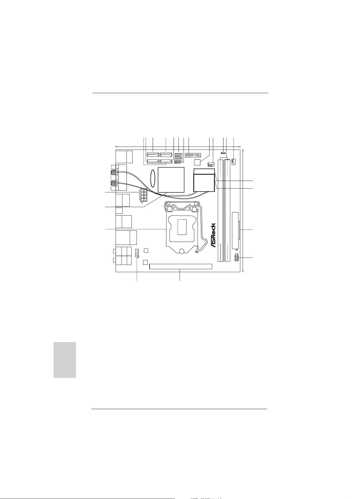
Motherboard Layout
English
3
2
1
17.0cm (6.7in)
USB 3.0
T:USBA1
B: USBA2
Mouse
Keyboard/
PS2
SATA3_0
SATA3_1
DVI1
CMOS
Battery
22
HDMI1
21
20
Clr
CMOS
ESATA1
USB 3.0
T: U SB 1
B: USB2
Bottom:
Optical
SPDIF
Bottom:
MIC IN
USB2.0
T:USB0
B:USB1
REAR SPK
FRONT
DP1
Center:
Center:
ATX12V1
Top:
RJ-45
Top:
CTR BASS
HD_AUDIO1
LAN
PHY
Top:
LINE IN
1
AUDIO
CODEC
19
1 SATA2 Connector (SATA_3, Black)
2 SATA3 Connector (SATA3_1, Gray)
3 SATA3 Connector (SATA3_0, Gray)
4 SATA2 Connector (SATA_2, Black)
5 USB 2.0 Header (USB2_3, Black)
6 USB 2.0 Header (USB4_5, Black)
7 Consumer Infrared Module Header
(CIR1, Gray)
8 USB 3.0 Header (USB3_3_4, Black)
9 SPI Flash Memory (64Mb)
10 CPU Fan Connector (CPU_FAN1)
11 Clear CMOS Jumper (CLRCMOS1)
12 2 x 240-pin DDR3 DIMM Slots
(DDR3_A1, DDR3_B1, Black)
4
SATA_2
SATA_3
Intel
Z77
RoHS
X
6
8
5
7
Front USB3.0
USB4_5
1
USB2_3
USB3_3_4
1
1
CIR1
64Mb
BIOS
9
CPU_FAN1
10
1
11
CLRCMOS1
13
12
CHA_FAN1
MINI_PCIE1
WiFi-802.11n
Module
ATXPWR1
DDR3_B1 (64bit, 240-pin module)
DDR3_A1 (64bit, 240-pin module)
Fast RAM
PCIE1
18
Z77E-ITX
PCI Express3.0
PLEDPWRBTN
PANEL1
13 Chassis Fan Connector (CHA_FAN1)
14 mini-PCI Express Slot (MINI_PCIE1)
15 WiFi-802.11n Module
16 ATX Power Connector (ATXPWR1)
17 System Panel Header (PANEL1, Black)
18 PCI Express 3.0 x16 Slot (PCIE1, Black)
19 Front Panel Audio Header
(HD_AUDIO1, Black)
20 1155-Pin CPU Socket
21 Intel Z77 Chipset
22 ATX 12V Power Connector (ATX12V1)
DDR3 2800+
HDLED RESET
1
14
15
17.0cm (6.7in)
16
17
2
ASRock Z77E-ITX Motherboard
Page 3
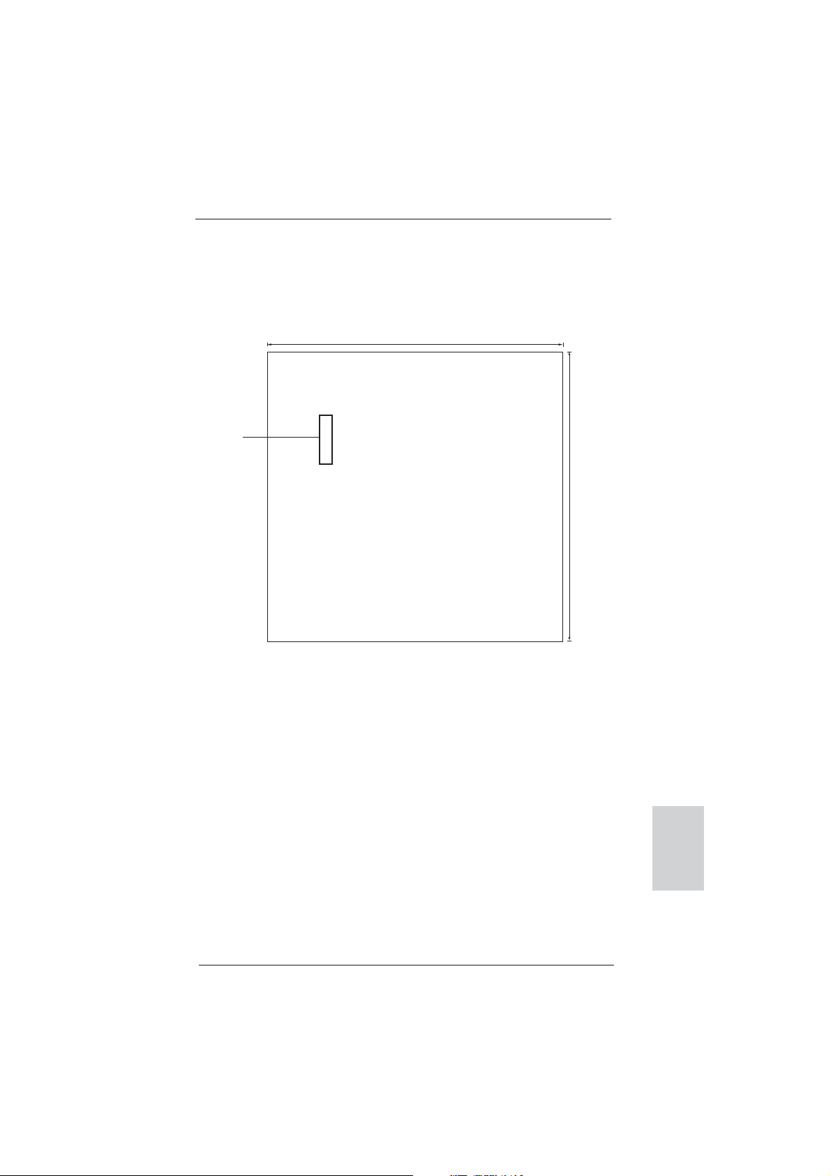
17.0cm (6.7in)
23
23 mSATA Connector (Black)
mSATA
17.0cm (6.7in)
ASRock Z77E-ITX Motherboard
English
3
Page 4
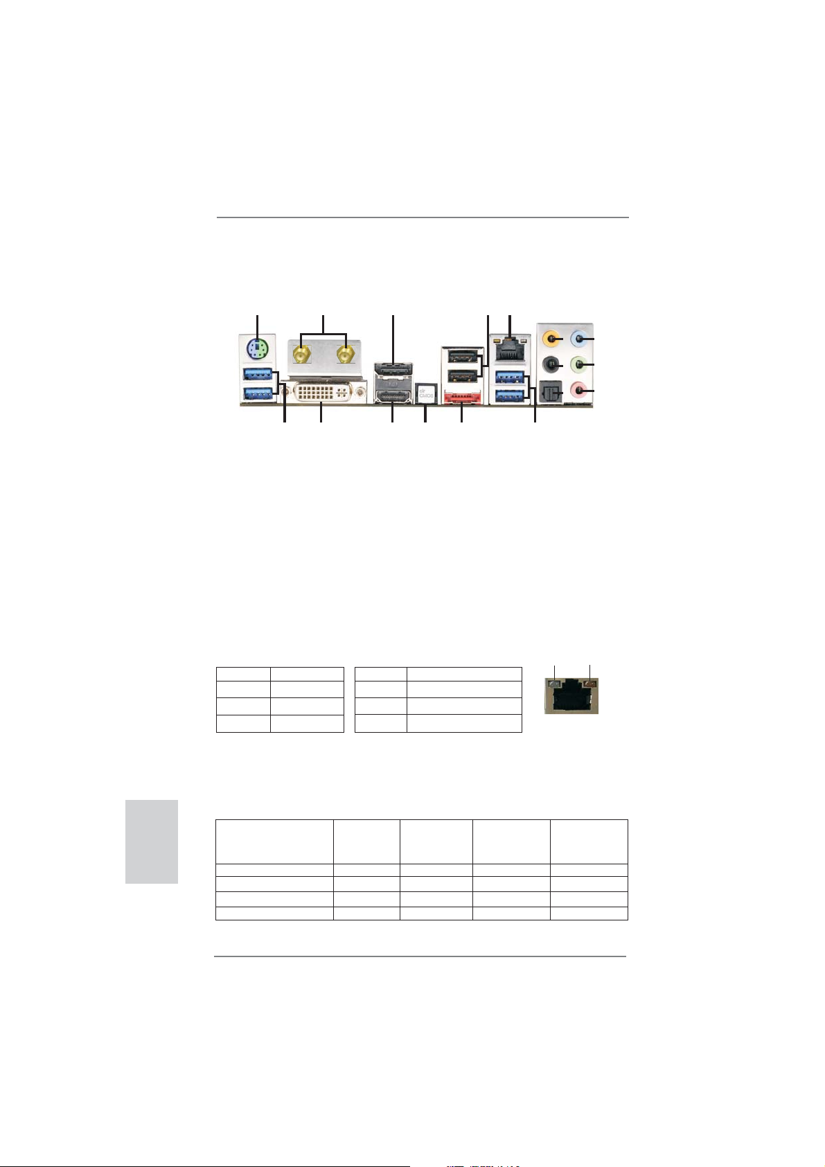
I/O Panel
1
2
17
1 PS/2 Keyboard/Mouse Port (Purple/Green)
2 Antenna Ports
3 DisplayPort (DP1)
4 USB 2.0 Ports (USB01)
* 5 LAN RJ-45 Port
6 Central / Bass (Orange)
7 Rear Speaker (Black)
8 Optical SPDIF Out Port
9 Line In (Light Blue)
* There are two LED next to the LAN port. Please refer to the table below for the LAN port LED
indications.
Activity/Link LED SPEED LED
Status Description Status Description
LAN Port LED Indications
3
13
141516
** 10 Front Speaker (Lime)
11 Microphone (Pink)
12 USB 3.0 Ports (USB3_12)
13 eSATA2 Connector (ESATA1)
14 Clear CMOS Switch (CLRCBTN)
15 HDMI Port (HDMI1)
16 DVI-I Port (DVI1)
17 USB 3.0 Ports (USB3_A1A2)
5
4
6
9
10
7
11
8
12
ACT/LINK
LED
SPEED
LED
Off No Link Off 10Mbps connection
Blinking Data Activity Orange 100Mbps connection
On Link Green 1Gbps connection
LAN Port
English
If you use 2-channel speaker, please connect the speaker’s plug into “Front Speaker Jack”.
**
See the table below for connection details in accordance with the type of speaker you use.
TABLE for Audio Output Connection
Audio Output Channels Front Speaker Rear Speaker Central / Bass Line in
(No. 10) (No. 7) (No. 6) (No. 9)
2 V -- -- -4 V V -- -6 V V V -8 V V V V
4
ASRock Z77E-ITX Motherboard
Page 5

To enable Multi-Streaming function, you need to connect a front panel audio cable to the front
panel audio header. After restarting your computer, you will fi nd “Mixer” tool on your system.
Please select “Mixer ToolBox” , click “Enable playback multi-streaming”, and click
“ok”. Choose “2CH”, “4CH”, “6CH”, or “8CH” and then you are allowed to select “Realtek HDA
Primary output” to use Rear Speaker, Central/Bass, and Front Speaker, or select “Realtek
HDA Audio 2nd output” to use front panel audio.
ASRock Z77E-ITX Motherboard
English
5
Page 6
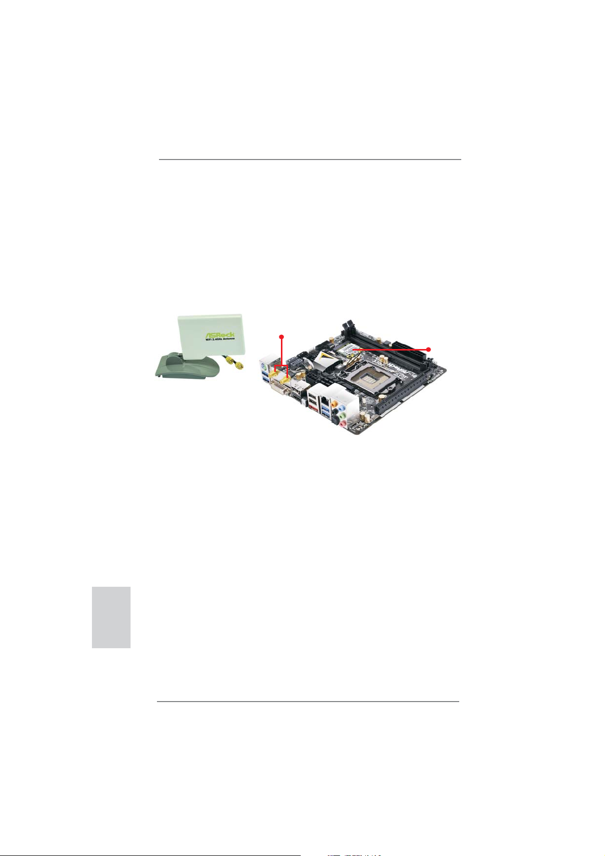
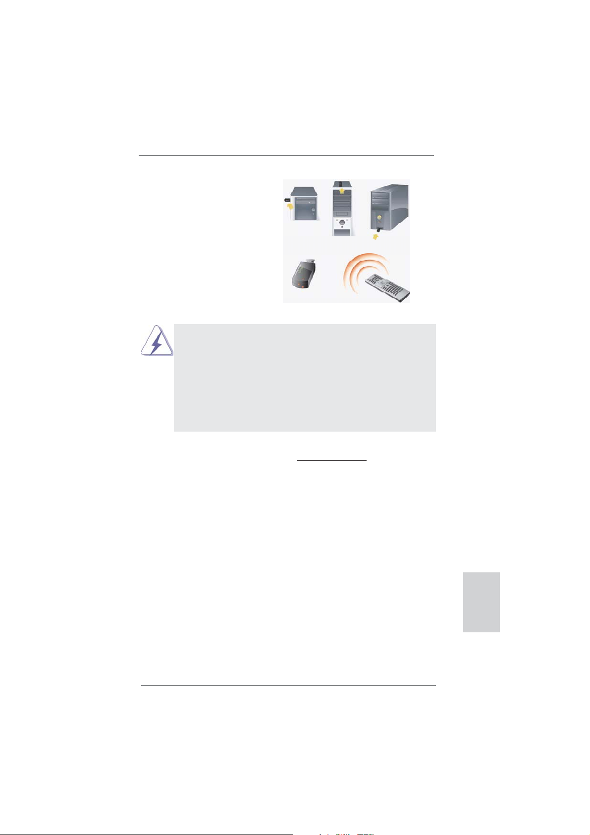
WiFi-802.11n Module and ASRock WiFi
2.4GHz Antenna
WiFi-802.11n module is an easy-to-use wireless local area network (WLAN) adapter
to support WiFi function. With WiFi-802.11n module, you can easily create a
wireless environment and enjoy the convenience of wireless network
connectivity. Therefore, from anywhere within the signal range, you will be able to
play LAN games, connect to the internet, access and share printers, and make
Internet phone calls easily.
Antenna Ports
WiFi-802.11n Module
ASRock WiFi 2.4GHz Antenna
WiFi-802.11n module supports Station mode. You can use the wireless function to
connect the access point (AP), or connect with other stations in the wireless range
instead. There are two choices provided in station mode: Infrastructure mode
and Ad-hoc mode. Please read below introduction for the differences of these two
modes.
English
Infrastructure Mode
If you have a present access point (AP) in your wireless network environment for
this station to join, you can set up WiFi-802.11n module in Infrastructure mode. In
this mode, WiFi-802.11n module acts as a wireless adapter. In other words, it is
centered on an AP that provides Internet access and LAN communication for the
wireless stations, such as PC, notebook and other devices.
Ad-hoc Mode
If you don’t have a present access point in your wireless network environment, you
can set up WiFi-802.11n module in Ad-hoc mode. The wireless network brings
together workstations, PC, notebook and other devices for wireless communication.
* The transmission speed may vary according to the environment.
6
ASRock Z77E-ITX Motherboard
Page 7
1. Introduction
Thank you for purchasing ASRock Z77E-ITX motherboard, a reliable motherboard
produced under ASRock’s consistently stringent quality control. It delivers excellent
performance with robust design conforming to ASRock’s commitment to quality and
endurance.
This Quick Installation Guide contains introduction of the motherboard and step-bystep installation guide. More detailed information of the motherboard can be found
in the user manual presented in the Support CD.
Because the motherboard specifi cations and the BIOS software might be
updated, the content of this manual will be subject to change without notice. In case any modifi cations of this manual occur, the updated version
will be available on ASRock website without further notice. You may fi nd
le
1.1 Package Contents
ASRock Z77E-ITX Motherboard
(Mini-ITX Form Factor: 6.7-in x 6.7-in, 17.0 cm x 17.0 cm)
ASRock Z77E-ITX Quick Installation Guide
ASRock Z77E-ITX Support CD
2 x Serial ATA (SATA) Data Cables (Optional)
1 x ASRock WiFi 2.4GHz Antenna (Optional)
1 x DVI-to-D-Sub Converter (Optional)
1 x I/O Panel Shield
the latest VGA cards and CPU support lists on ASRock website as well.
ASRock website http://www.asrock.com
If you require technical support related to this motherboard, please visit
our website for specifi c information about the model you are using.
www.asrock.com/support/index.asp
ASRock Reminds You...
To get better performance in Windows® 7 / 7 64-bit / Vista
bit, it is recommended to set the BIOS option in Storage Confi guration to
AHCI mode. For the BIOS setup, please refer to the “User Manual” in our
support CD for details.
TM
/ VistaTM 64-
ASRock Z77E-ITX Motherboard
English
7
Page 8
English
1.2 Specifications
Platform - Mini-ITX Form Factor: 6.7-in x 6.7-in, 17.0 cm x 17.0 cm
- Premium Gold Capacitor design (100% Japan-made
high-quality Conductive Polymer Capacitors)
CPU - Supports 3
LGA1155 Package
- Digi Power Design
- 6 + 2 Power Phase Design
- Supports Intel® Turbo Boost 2.0 Technology
- Supports Intel
- Supports Hyper-Threading Technology (see CAUTION 1)
- Supports Intel® Rapid Start Technology and Smart Connect
Technology with Intel
Chipset - Intel® Z77
Memory - Dual Channel DDR3 Memory Technology (see CAUTION 2)
- 2 x DDR3 DIMM slots
- Supports DDR3 2800+(OC)/2400(OC)/2133(OC)/1866(OC)/
1600/1333/1066 non-ECC, un-buffered memory
- Max. capacity of system memory: 16GB (see CAUTION 3)
- Supports Intel
Expansion Slot - 1 x PCI Express 3.0 x16 slot (PCIE1: x16 mode)
(see CAUTION 4)
* PCIE 3.0 is only supported with Intel
Intel® Sandy Bridge CPU, it only supports PCIE 2.0.
- 1 x mini-PCI Express slot: For WiFi module
Graphics * Intel
be supported only with processors which are GPU
integrated.
- Supports Intel® HD Graphics Built-in Visuals: Intel® Quick
Sync Video 2.0, Intel
Technology, Intel® InsiderTM, Intel® HD Graphics 2500/4000
- Pixel Shader 5.0, DirectX 11 with Intel® Ivy Bridge CPU.
Pixel Shader 4.1, DirectX 10.1 with Intel® Sandy Bridge
CPU.
- Max. shared memory 1760MB (see CAUTION 5)
- Multi VGA Output options: DVI, HDMI, DisplayPort and
D-Sub with the bundled DVI-to-D-Sub Converter
(see CAUTION 6)
- Supports HDMI 1.4a Technology with max. resolution up to
1920x1200 @ 60Hz
rd
and 2nd Generation Intel® CoreTM i7 / i5 / i3 in
®
K-Series unlocked CPU
®
Ivy Bridge CPU
®
Extreme Memory Profi le (XMP)1.3/1.2
®
Ivy Bridge CPU. With
®
HD Graphics Built-in Visuals and the VGA outputs can
®
InTruTM 3D, Intel® Clear Video HD
8
ASRock Z77E-ITX Motherboard
Page 9
- Supports DVI with max. resolution up to 1920x1200 @ 60Hz
- Supports DisplayPort with max. resolution up to 2560x1600
@ 60Hz
- Supports D-Sub with max. resolution up to 2048x1536 @
75Hz
- Supports Auto Lip Sync, Deep Color (12bpc), xvYCC and
HBR (High Bit Rate Audio) with HDMI (Compliant HDMI
monitor is required) (see CAUTION 7)
- Supports HDCP function with DVI, HDMI and DisplayPort
ports
- Supports Full HD 1080p Blu-ray (BD) / HD-DVD playback
with DVI, HDMI and DisplayPort ports
Audio - 7.1 CH HD Audio with Content Protection
(Realtek ALC898 Audio Codec)
- Premium Blu-ray audio support
- Supports THX TruStudio
TM
LAN - PCIE x1 Gigabit LAN 10/100/1000 Mb/s
- Broadcom BCM57781
- Supports Wake-On-LAN
- Supports Energy Effi cient Ethernet 802.3az
- Supports PXE
Wireless LAN WiFi-802.11n module
- 300Mbps IEEE 802.11n / 54Mbps IEEE 802.11g /
11Mbps IEEE 802.11b
- Supports Station mode (Infrastructure mode and Ad-hoc
mode)
Rear Panel I/O I/O Panel
- 2 x Antenna Ports
- 1 x PS/2 Mouse/Keyboard Port
- 1 x DVI-I Port
- 1 x HDMI Port
- 1 x DisplayPort
- 1 x Optical SPDIF Out Port
- 2 x Ready-to-Use USB 2.0 Ports
- 1 x eSATA2 Connector
- 4 x Ready-to-Use USB 3.0 Ports
- 1 x RJ-45 LAN Port with LED (ACT/LINK LED and SPEED
LED)
- 1 x Clear CMOS Switch with LED
- HD Audio Jack: Rear Speaker/Central/Bass/Line in/Front
Speaker/Microphone (see CAUTION 8)
English
ASRock Z77E-ITX Motherboard
9
Page 10
English
SATA 3 - 2 x SATA3 6.0 Gb/s connectors, support RAID (RAID 0,
RAID 1, RAID 5, RAID 10, Intel Rapid Storage and Intel
Smart Response Technology), NCQ, AHCI and Hot Plug
functions
®
USB3.0 - 2 x Rear USB 3.0 ports by Intel
Z77, support USB 1.0/2.0/3.0
up to 5Gb/s
- 2 x Rear USB 3.0 ports by ASMedia ASM1042, support USB
1.0/2.0/3.0 up to 5Gb/s
- 1 x Front USB 3.0 header (supports 2 USB 3.0 ports) by
Intel
®
Z77, supports USB 1.0/2.0/3.0 up to 5Gb/s
Connector - 2 x SATA2 3.0 Gb/s connectors, support RAID (RAID 0,
RAID 1, RAID 5, RAID 10, Intel Rapid Storage and Intel
Smart Response Technology), NCQ, AHCI and Hot Plug
functions
- 1 x mSATA 3.0 Gb/s connector (Solid-State Drive
connector), supports RAID (RAID 0, RAID 1, RAID 5, RAID
10, Intel Rapid Storage and Intel Smart Response
Technology), NCQ, AHCI functions and Full-size mini-PCI
Express modules
- 2 x SATA3 6.0Gb/s connectors
- 1 x CIR header
- CPU/Chassis FAN connector
- 24 pin ATX power connector
- 8 pin 12V power connector
- Front panel audio connector
- 2 x USB 2.0 headers (support 4 USB 2.0 ports)
- 1 x USB 3.0 header (supports 2 USB 3.0 ports)
BIOS Feature - 64Mb AMI UEFI Legal BIOS with GUI support
- Supports “Plug and Play”
- ACPI 1.1 Compliance Wake Up Events
- Supports jumperfree
- SMBIOS 2.3.1 Support
- CPU Core, IGPU, DRAM, VCCSA Voltage Multi-adjustment
Support CD - Drivers, Utilities, AntiVirus Software (Trial Version),
CyberLink MediaEspresso 6.5 Trial, ASRock MAGIX
Multimedia Suite - OEM
Unique Feature - ASRock Extreme Tuning Utility (AXTU) (see CAUTION 9)
- ASRock Instant Boot
- ASRock Instant Flash (see CAUTION 10)
- ASRock APP Charger (see CAUTION 11)
- ASRock SmartView (see CAUTION 12)
10
ASRock Z77E-ITX Motherboard
Page 11
- ASRock XFast USB (see CAUTION 13)
- ASRock XFast LAN (see CAUTION 14)
- ASRock XFast RAM (see CAUTION 15)
- ASRock Crashless BIOS (see CAUTION 16)
- ASRock OMG (Online Management Guard)
(see CAUTION 17)
- ASRock Internet Flash (see CAUTION 18)
- Lucid Virtu Universal MVP (see CAUTION 19)
* Lucid Virtu Universal MVP can be supported only with
processors which are GPU integrated.
- Hybrid Booster:
- CPU Frequency Stepless Control (see CAUTION 20)
- ASRock U-COP (see CAUTION 21)
- Boot Failure Guard (B.F.G.)
- Good Night LED
Hardware - CPU Temperature Sensing
Monitor - Chassis Temperature Sensing
- CPU Fan Tachometer
- Chassis Fan Tachometer
- CPU/Chassis Quiet Fan (Allows Chassis Fan Speed Auto Adjust by CPU Temperature)
- CPU/Chassis Fan Multi-Speed Control
- Voltage Monitoring: +12V, +5V, +3.3V, CPU Vcore
OS - Microsoft
®
Windows® 7 / 7 64-bit / VistaTM / VistaTM 64-bit /
XP / XP 64-bit compliant (see CAUTION 22)
Certifi cations - FCC, CE, WHQL
- ErP/EuP Ready (ErP/EuP ready power supply is required)
(see CAUTION 23)
* For detailed product information, please visit our website: http://www.asrock.com
WARNING
Please realize that there is a certain risk involved with overclocking, including
adjusting the setting in the BIOS, applying Untied Overclocking Technology, or using
third-party overclocking tools. Overclocking may affect your system’s stability, or
even cause damage to the components and devices of your system. It should be
done at your own risk and expense. We are not responsible for possible damage
caused by overclocking.
ASRock Z77E-ITX Motherboard
English
11
Page 12

English
CAUTION!
1. About the settings of “Hyper Threading Technology”, please check page
47 of the “User Manual” in the support CD.
2. This motherboard supports Dual Channel Memory Technology. Before
you implement Dual Channel Memory Technology, make sure to read the
installation guide of memory modules on page 19 for proper installation.
3. Due to the operating system limitation, the actual memory size may be
less than 4GB for the reservation for system usage under Windows
TM
Vista
/ XP. For Windows® OS with 64-bit CPU, there is no such limita-
tion. You can use ASRock XFast RAM to utilize the memory that Win-
dows® cannot use.
4. Only PCIE1 slot supports Gen 3 speed. To run the PCI Express in Gen
3 speed, please install an Ivy Bridge CPU. If you install a Sandy Bridge
CPU, the PCI Express will run only at PCI Express Gen 2 speed.
5. The maximum shared memory size is defi ned by the chipset vendor and
is subject to change. Please check Intel
®
website for the latest informa-
tion.
6. You can choose to use two of the three monitors only. DVI, HDMI and
DisplayPort monitors cannot be enabled at the same time. Besides, with
the DVI-to-HDMI adapter, the DVI port can support the same features as
HDMI port.
7. xvYCC and Deep Color are only supported under Windows
7. Deep Color mode will be enabled only if the display supports 12bpc
in EDID. HBR is supported under Windows® 7 64-bit / 7 / VistaTM 64-bit /
TM
Vista
.
8. For microphone input, this motherboard supports both stereo and mono
modes. For audio output, this motherboard supports 2-channel, 4-channel, 6-channel, and 8-channel modes. Please check the table on page 4
for proper connection.
9. ASRock Extreme Tuning Utility (AXTU) is an all-in-one tool to ne-tune different system functions in a user-friendly interface, which includes Hardware Monitor, Fan Control, Overclocking, OC DNA and IES. In Hardware
Monitor, it shows the major readings of your system. In Fan Control, it
shows the fan speed and temperature for you to adjust. In Overclocking,
you are allowed to overclock CPU frequency for optimal system performance. In OC DNA, you can save your OC settings as a profi le and
share it with your friends. Your friends then can load the OC profi le to
their own system to get the same OC settings. In IES (Intelligent Energy
Saver), the voltage regulator can reduce the number of output phases to
improve effi ciency when the CPU cores are idle without sacrifi cing
computing performance. Please visit our website for the operation proce-
dures of ASRock Extreme Tuning Utility (AXTU).
ASRock website: http://www.asrock.com
10. ASRock Instant Flash is a BIOS fl ash utility embedded in Flash ROM.
This convenient BIOS update tool allows you to update system BIOS
®
®
7 64-bit /
7 /
12
ASRock Z77E-ITX Motherboard
Page 13

without entering operating systems fi rst like MS-DOS or Windows®. With
this utility, you can press the <F6> key during the POST or the <F2>
key to enter into the BIOS setup menu to access ASRock Instant Flash.
Just launch this tool and save the new BIOS fi le to your USB fl ash drive,
fl oppy disk or hard drive, then you can update your BIOS only in a few
clicks without preparing an additional fl oppy diskette or other complicated
fl ash utility. Please be noted that the USB fl ash drive or hard drive must
use FAT32/16/12 fi le system.
11. If you desire a faster, less restricted way of charging your Apple devices,
such as iPhone/iPad/iPod Touch, ASRock has prepared a wonderful solution for you - ASRock APP Charger. Simply install the APP Charger
driver, it makes your iPhone charge much quickly from your computer
and up to 40% faster than before. ASRock APP Charger allows you to
quickly charge many Apple devices simultaneously and even supports
continuous charging when your PC enters into Standby mode (S1), Sus-
pend to RAM (S3), hibernation mode (S4) or power off (S5). With APP
Charger driver installed, you can easily enjoy the marvelous charging
experience.
ASRock website: http://www.asrock.com/Feature/AppCharger/index.asp
12. ASRock SmartView, a new function for internet browsers, is the smart
start page for IE that combines your most visited web sites, your history,
your Facebook friends and your real-time newsfeed into an enhanced
view for a more personal Internet experience. ASRock motherboards are
exclusively equipped with the ASRock SmartView utility that helps you
keep in touch with friends on-the-go. To use ASRock SmartView feature,
please make sure your OS version is Windows
VistaTM 64 bit, and your browser version is IE8.
ASRock website: http://www.asrock.com/Feature/SmartView/index.asp
13. ASRock XFast USB can boost USB storage device performance. The
performance may depend on the properties of the device.
14. ASRock XFast LAN provides a faster internet access, which includes
the benefi ts listed below. LAN Application Prioritization: You can confi g-
ure your application’s priority ideally and/or add new programs. Lower
Latency in Game: After setting online game’s priority higher, it can lower
the latency in games. Traffi c Shaping: You can watch Youtube HD videos
and download simultaneously. Real-Time Analysis of Your Data: With
the status window, you can easily recognize which data streams you are
transferring currently.
15. ASRock XFast RAM is a new function that is included into ASRock Extreme Tuning Utility (AXTU). It fully utilizes the memory space that cannot
be used under Windows
the loading time of previously visited websites, making web surfi ng faster
than ever. And it also boosts the speed of Adobe Photoshop 5 times
faster. Another advantage of ASRock XFast RAM is that it reduces the
frequency of accessing your SSDs or HDDs in order to extend their lifes-
pan.
®
OS 32-bit CPU. ASRock XFast RAM shortens
®
7 / 7 64 bit / VistaTM /
English
ASRock Z77E-ITX Motherboard
13
Page 14

English
16. ASRock Crashless BIOS allows users to update their BIOS without fear
of failing. If power loss occurs during the BIOS update process, ASRock
Crashless BIOS will automatically fi nish the BIOS update procedure after
regaining power. Please note that BIOS fi les need to be placed in the root
directory of your USB disk. Only USB2.0 ports support this feature.
17. Administrators are able to establish an internet curfew or restrict internet
access at specifi ed times via OMG. You may choose from [Everyday], [Day
of the week] or [Weekdays and weekends], then schedule the starting
and ending hours of internet access granted to other users. In order to
prevent users from bypassing OMG, guest accounts without permission
to modify the system time are required.
18. ASRock Internet Flash searches for available UEFI firmware updates
from our servers. In other words, the system can auto-detect the latest
UEFI from our servers and fl ash them without entering Windows
Please note that you must be running on a DHCP confi gured computer in
order to enable this function.
19. VIRTU Universal MVP includes the base features of Virtu Universal
technology, which virtualizes integrated GPU and discrete GPU for best
of breed functionality. It also features Virtual Vsync™ for no-compromise
visual quality. With the added benefits of HyperFormance technology,
VIRTU Universal MVP improves game performance by intelligently reducing redundant rendering tasks in the fl ow between the CPU, GPU and the
display.
20. Although this motherboard offers stepless control, it is not recommended
to perform over-clocking. Frequencies other than the recommended CPU
bus frequencies may cause instability of the system or damage the CPU.
21. While CPU overheat is detected, the system will automatically shutdown.
Before you resume the system, please check if the CPU fan on the motherboard functions properly and unplug the power cord, then plug it back
again. To improve heat dissipation, remember to spray thermal grease
between the CPU and the heatsink when you install the PC system.
22. ASRock XFast RAM is not supported by Microsoft® Windows® XP / XP
64-bit. Intel® Smart Connect Technology and Intel® USB 3.0 ports are not
supported by Microsoft® Windows® VistaTM / VistaTM 64-bit / XP / XP 64-
bit
.
23. EuP stands for Energy Using Product, w
European Union to define the power consumption for the completed
system. According to EuP, the total AC power of the completed system
should be under 1.00W in off mode condition. To meet EuP standards,
an EuP ready motherboard and an EuP ready power supply are required.
According to Intel’s suggestion, the EuP ready power supply must meet
the standard of 5v, and the standby power effi ciency should be higher
than 50% under 100 mA current consumption. For EuP ready power supply selection, we recommend you to check with the power supply manufacturer for more details.
as a provision regulated by the
®
OS.
14
ASRock Z77E-ITX Motherboard
Page 15
2. Installation
This is a Mini-ITX form factor (6.7” x 6.7”, 17.0 x 17.0 cm) motherboard. Before you
install the motherboard, study the confi guration of your chassis to ensure that the
motherboard fi ts into it.
motherboard. Failure to do so may cause physical injuries to you and
damages to motherboard components.
Make sure to unplug the power cord before installing or removing the
2.1 Screw Holes
Place screws into the holes indicated by circles to secure the motherboard to the
chassis.
Do not over-tighten the screws! Doing so may damage the motherboard.
2.2 Pre-installation Precautions
Take note of the following precautions before you install motherboard components
or change any motherboard settings.
1. Unplug the power cord from the wall socket before touching any
components.
2. To avoid damaging the motherboard’s components due to static
electricity, NEVER place your motherboard directly on the carpet
or the like. Also remember to use a grounded wrist strap or touch a
safety grounded object before you handle the components.
3. Hold components by the edges and do not touch the ICs.
4. Whenever you uninstall any component, place it on a grounded antistatic pad or in the bag that comes with the component.
5. When placing screws into the screw holes to secure the motherboard to the chassis, please do not over-tighten the screws! Doing
so may damage the motherboard.
Before you install or remove any component, ensure that the power is
switched off or the power cord is detached from the power supply. Failure to do
so may cause severe damage to the motherboard, peripherals, and/or
components.
ASRock Z77E-ITX Motherboard
English
15
Page 16
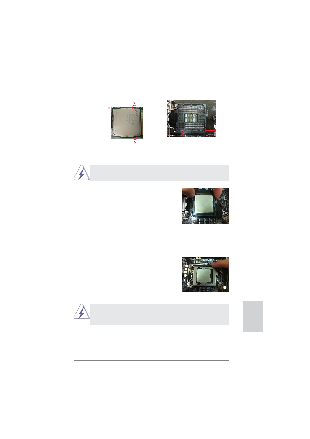
2.3 CPU Installation
In order to provide the LGA 1155 CPU sockets more protection and make the installation process easier, ASRock has added
a new protection cover on top of the load
plate to replace the former PnP caps that
were under the load plate. For the installation of Intel
protection cover, please follow the steps
below.
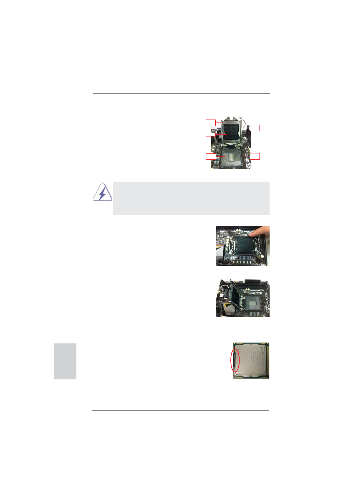
Step 1. Open the socket:
®
1155-Pin CPUs with the new
Before you insert the 1155-Pin CPU into the socket, please check if the
CPU surface is unclean or if there are any bent pins in the socket. Do
not force to insert the CPU into the socket if above situation is found.
Otherwise, the CPU will be seriously damaged.
Step 1-1. Disengage the lever by pressing it
down and sliding it out of the hook.
You do not have to remove the protection cover.
Step 1-2. Keep the lever positioned at about
135 degrees in order to flip up the
load plate.
Load
Plate
Cover
Contact
Array
1155-Pin Socket Overview
Load
Lever
Socket
Body
English
Step 2. Insert the 1155-Pin CPU:
Step 2-1. Hold the CPU by the edge which is
marked with a black line.
Step 2-2. Orient the CPU with the IHS (Inte-
grated Heat Sink) up. Locate Pin1
and the two orientation key notches.
16
black line
ASRock Z77E-ITX Motherboard
Page 17
orientation key notch
Pin1
alignment key
Pin1
orientation key notch
1155-Pin CPU
For proper installation, please ensure to match the two orientation
key notches of the CPU with the two alignment keys of the socket.
Step 2-3. Carefully place the CPU into the
socket.
Step 2-4. Verify that the CPU is within the sock-
et and properly mated to the orient
keys.
Step 3. Close the socket:
Step 3-1. Flip the load plate onto the IHS.
Step 3-2. Press down the load lever, and se-
cure it with the load plate tab under
the retention tab. The protection
cover will automatically come off by
itself.
alignment key
1155-Pin Socket
Please save and replace the cover if the processor is removed. The
cover must be placed if you wish to return the motherboard for after
service.
ASRock Z77E-ITX Motherboard
English
17
Page 18

2.4 Installation of CPU Fan and Heatsink
This motherboard is equipped with 1155-Pin socket that supports Intel 1155-Pin
CPUs. Please adopt the type of heatsink and cooling fan compliant with Intel 1155Pin CPU to dissipate heat. Before you install the heatsink, you need to spray thermal interface material between the CPU and the heatsink to improve heat dissipation. Ensure that the CPU and the heatsink are securely fastened and in good contact with each other. Then connect the CPU fan to the CPU_FAN connector (CPU_
FAN1, see page 2, No. 10).
For proper installation, please kindly refer to the instruction manuals of your
CPU fan and heatsink.
Below is an example to illustrate the installation of the heatsink for 1155-Pin CPUs.
Step 1. Apply thermal interface material onto the cen-
ter of the IHS on the socket’s surface.
Apply Thermal
Interface Material
English
Step 2. Place the heatsink onto the socket. Ensure
that the fan cables are oriented on side closest
Fan cableson side
closest toMB header
to the CPU fan connector on the motherboard
(CPU_FAN1, see page 2, No. 10).
Step 3. Align fasteners with the motherboard through-
Fastener slots
pointing straightout
holes.
Step 4. Rotate the fastener clockwise, then press
down on fastener caps with thumb to install
and lock. Repeat with remaining fasteners.
If you press down the fasteners without rotating them clockwise, the
heatsink cannot be secured on the motherboard.
Press Down
(4 Places)
Step 5. Connect fan header with the CPU fan connector on the motherboard.
Step 6. Secure redundant cable with tie-wrap to ensure the cable does not
interfere with fan operation or contact other components.
18
ASRock Z77E-ITX Motherboard
Page 19
2.5 Installation of Memory Modules (DIMM)
This motherboard provides two 240-pin DDR3 (Double Data Rate 3) DIMM slots,
and supports Dual Channel Memory Technology. For dual channel configuration,
you always need to install two identical (the same brand, speed, size and chiptype) memory modules in the DDR3 DIMM slots to activate Dual Channel Memory
Technology. Otherwise, it will operate at single channel mode.
1. It is not allowed to install a DDR or DDR2 memory module into
DDR3 slot;otherwise, this motherboard and DIMM may be
damaged.
2. If you install only one memory module or two non-identical
memory modules, it is unable to activate the Dual Channel
Memory Technology.
3. Some DDR3 1GB double-sided DIMMs with 16 chips may not
work on this motherboard. It is not recommended to install them
on this motherboard.
Installing a DIMM
Please make sure to disconnect power supply before adding or
removing DIMMs or the system components.
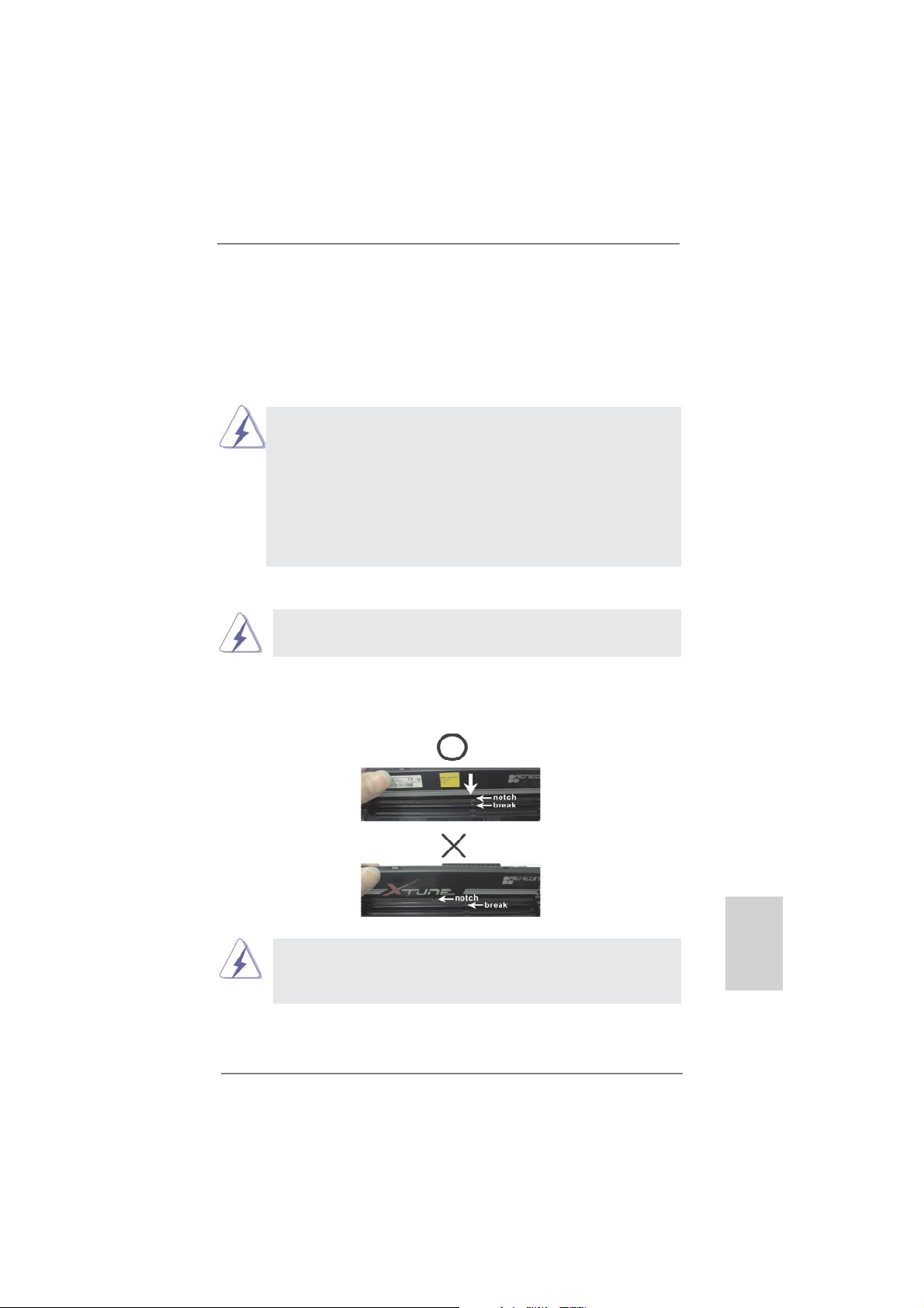
Step 1. Unlock a DIMM slot by pressing the retaining clips outward.
Step 2. Align a DIMM on the slot such that the notch on the DIMM matches the
break on the slot.
The DIMM only fi ts in one correct orientation. It will cause permanent
damage to the motherboard and the DIMM if you force the DIMM into
the slot at incorrect orientation.
Step 3. Firmly insert the DIMM into the slot until the retaining clips at both ends
fully snap back in place and the DIMM is properly seated.
ASRock Z77E-ITX Motherboard
English
19
Page 20
2.6 Expansion Slots (PCI Express Slots)
There is 1 PCI Express slot and 1 mini-PCI Express slot on this motherboard.
PCIE slots: PCIE1 (PCIE 3.0 x16 slot) is used for PCI Express x16 lane width
graphics cards.
MINI_PCIE1 (mini-PCIE slot) is used for WiFi module.
Only PCIE1 slot supports Gen 3 speed. To run the PCI Express in Gen
3 speed, please install an Ivy Bridge CPU. If you install a Sandy Bridge
CPU, the PCI Express will run only at PCI Express Gen 2 speed.
Installing an expansion card
Step 1. Before installing an expansion card, please make sure that the power
supply is switched off or the power cord is unplugged. Please read the
documentation of the expansion card and make necessary hardware
settings for the card before you start the installation.
Step 2. Remove the system unit cover (if your motherboard is already installed
in a chassis).
Step 3. Remove the bracket facing the slot that you intend to use. Keep the
screws for later use.
Step 4. Align the card connector with the slot and press fi rmly until the card is
completely seated on the slot.
Step 5. Fasten the card to the chassis with screws.
Step 6. Replace the system cover.
English
20
ASRock Z77E-ITX Motherboard
Page 21
2.7 Dual Monitor and Surround Display Features
Dual Monitor Feature
This motherboard supports dual monitor feature. With the internal VGA output support (DVI, HDMI and DisplayPort), you can easily enjoy the benefi ts of dual monitor
feature without installing any add-on VGA cards to this motherboard. This motherboard also provides independent display controllers for DVI, HDMI and DisplayPort
to support dual VGA output so that DVI, HDMI and DisplayPort can drive same or
different display contents.
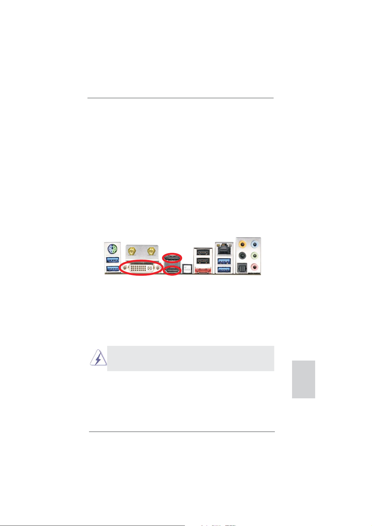
To enable dual monitor feature, please follow the steps below:
1. Connect a DVI monitor cable to the DVI port on the I/O panel, connect a
HDMI monitor cable to the HDMI port on the I/O panel and connect a DisplayPort
monitor cable to the DisplayPort on the I/O panel.
DisplayPort
HDMI portDVI-I port
2. If you have already installed the onboard VGA driver from our support CD to your
system, you can freely enjoy the benefi ts of dual monitor function after your
system boots. If you haven’t installed the onboard VGA driver yet, please install
the onboard VGA driver from our support CD to your system and restart your
computer.
DVI, HDMI and DisplyPort monitors cannot be enabled at the same time.
You can only choose the combination: DVI + HDMI, DVI + DisplayPort, or
HDMI + DisplayPort.
ASRock Z77E-ITX Motherboard
English
21
Page 22

Surround Display Feature
This motherboard supports surround display upgrade. With the internal VGA output
support (DVI, HDMI and DisplayPort) and external add-on PCI Express VGA cards,
you can easily enjoy the benefi ts of surround display feature.
Please refer to the following steps to set up a surround display environment:
1. Install the PCI Express VGA cards on PCIE1 slot. Please refer to page 20 for
proper expansion card installation procedures.
2. Connect a DVI monitor cable to the DVI port on the I/O panel, connect a
HDMI monitor cable to the HDMI port on the I/O panel and connect a DisplayPort
monitor cable to the DisplayPort port on the I/O panel. Then connect other
monitor cables to the corresponding connectors of the add-on PCI Express VGA
cards on PCIE1 slot.
3. Boot your system. Press <F2> or <Del> to enter UEFI setup. Enter “Share
Memory” option to adjust the memory capability to [32MB], [64MB], [128MB],
[256MB] or [512MB] to enable the function of D-sub. Please make sure that the
value you select is less than the total capability of the system memory. If you do
not adjust the UEFI setup, the default value of “Share Memory”, [Auto], will
disable D-Sub function when an add-on VGA card is inserted to this motherboard.
4. Install the onboard VGA driver and the add-on PCI Express VGA card driver to
your system. If you have installed the drivers already, there is no need to install
them again.
5. Set up a multi-monitor display.
English
For Windows
®
XP / XP 64-bit OS:
Right click on desktop, choose “Properties”, and select the “Settings” tab
so that you can adjust the parameters of the multi-monitors according to
the steps below.
A. Click the “Identify” button to display a large number on each monitor.
B. Right-click the display icon in the Display Properties dialog that you
wish to be your primary monitor, and then select “Primary”. When
you use multiple monitors with your card, one monitor will always be
Primary, and all additional monitors will be designated as Secondary.
C. Select the display icon identifi ed by the number 2.
D. Click “Extend my Windows desktop onto this monitor”.
E. Right-click the display icon and select “Attached”, if necessary.
F. Set the appropriate “Screen Resolution” and “Color Quality” for the
second monitor. Click “Apply” or “OK” to apply these new values.
G. Repeat steps C through E for the display icon identifi ed by the
numbers three to four.
22
ASRock Z77E-ITX Motherboard
Page 23

For Windows® 7 / 7 64-bit OS:
Right click the desktop, choose “Personalize”, and select the “Display
Settings” tab so that you can adjust the parameters of the multi-monitors
according to the steps below.
A. Click the number ”2” icon.
B. Click the items “This is my main monitor” and “Extend the desktop onto
this monitor”.
C. Click “OK” to save your change.
D. Repeat steps A through C for the display icons identifi ed by the number
three to four.
6. Use Surround Display. Click and drag the display icons to positions representing
the physical setup of your monitors that you would like to use. The placement of
display icons determines how you move items from one monitor to another.
HDCP Function
HDCP function is supported on this motherboard. To use HDCP
function with this motherboard, you need to adopt a monitor
that supports HDCP function as well. Therefore, you can enjoy
the superior display quality with high-defi nition HDCP
encryption contents. Please refer to the instructions below for
more details about HDCP function.
What is HDCP?
HDCP stands for High-Bandwidth Digital Content Protection, a
specifi cation developed by Intel
®
for protecting digital
entertainment content that uses the DVI interface. HDCP is a
copy protection scheme to eliminate the possibility of
intercepting digital data midstream between the video source,
or transmitter - such as a computer, DVD player or set-top box -
and the digital display, or receiver - such as a monitor, television
or projector. In other words, HDCP specifi cation is designed to
protect the integrity of content as it is being transmitted.
Products compatible with the HDCP scheme such as DVD
players, satellite and cable HDTV set-top-boxes, as well as few
entertainment PCs requires a secure connection to a compliant
display. Due to the increase in manufacturers employing HDCP
in their equipment, it is highly recommended that the HDTV or
LCD monitor you purchase is compatible.
ASRock Z77E-ITX Motherboard
English
23
Page 24
2.8 ASRock Smart Remote Installation Guide
ASRock Smart Remote is only used for ASRock motherboard with CIR header.
Please refer to below procedures for the quick installation and usage of ASRock
Smart Remote.
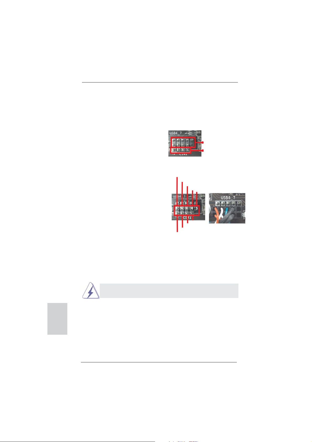
Step1. Find the CIR header located next
to the USB 2.0 header on ASRock
motherboard.
USB 2.0 header (9-pin, black)
CIR header (4-pin, gray)
English
Step2. Connect the front USB cable to the
USB 2.0 header (as below, pin 1-5)
and the CIR header. Please make
USB_PWR
P-
P+
GND
DUMMY
sure the wire assignments and the
pin assignments are matched
correctly.
GND
IRTX
IRRX
ATX+5VSB
Step3. Install Multi-Angle CIR Receiver to the front USB port.
Step4. Boot up your system. Press <F2> or <Del> to enter BIOS Setup Utility.
Make sure the option "CIR Controller" is setting at [Enabled].
(Advanced -> Super IO Confi guration -> CIR Controller -> [Enabled])
If you cannot fi nd this option, please shut down your system and install
Multi-Angle CIR Receiver to the other front USB port then try again.
Step5. Enter Windows. Execute ASRock support CD and install CIR Driver. (It is
listed at the bottom of driver list.)
24
ASRock Z77E-ITX Motherboard
Page 25
3 CIR sensors in different angles
1. Only one of the front USB port can support CIR function. When
the CIR function is enabled, the other port will remain USB
function.
2. Multi-Angle CIR Receiver
not use the rear USB bracket to connect it on the rear panel.
Multi-Angle CIR Receiver can receive the multi-direction infrared
signals (top, down and front), which is compatible with most of
the chassis on the market.
3. The Multi-Angle CIR Receiver does not support Hot-Plug
function. Please install it before you boot the system.
* ASRock Smart Remote is only supported by some of ASRock motherboards. Please refer to
ASRock website for the motherboard support list: http://www.asrock.com
is used for front USB only. Please do
ASRock Z77E-ITX Motherboard
English
25
Page 26
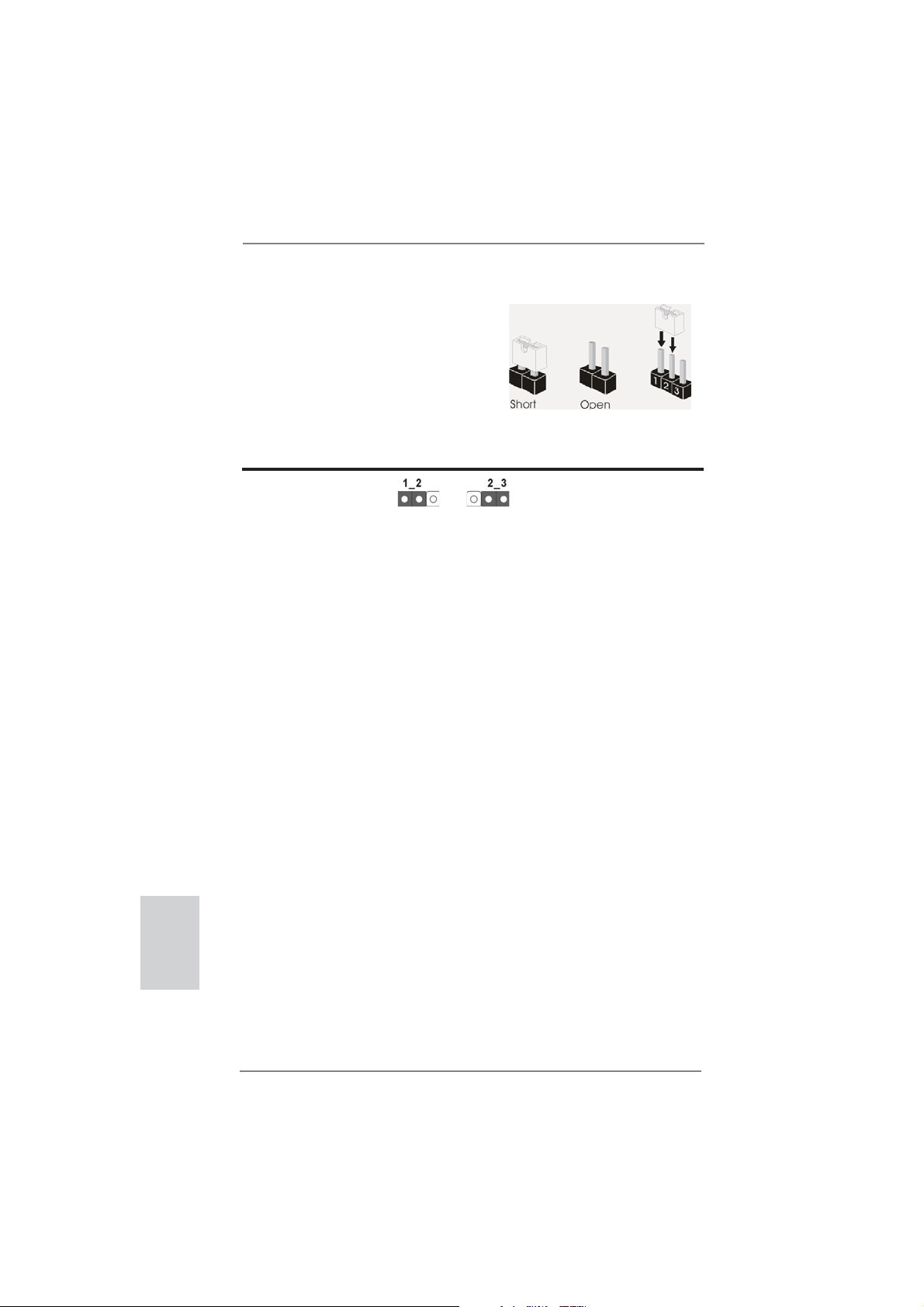
2.9 Jumpers Setup
The illustration shows how jumpers are
setup. When the jumper cap is placed on
pins, the jumper is “Short”. If no jumper cap
is placed on pins, the jumper is “Open”. The
illustration shows a 3-pin jumper whose
pin1 and pin2 are “Short” when jumper cap
is placed on these 2 pins.
Jumper Setting Description
Clear CMOS Jumper
(CLRCMOS1)
(see p.2, No. 11)
Note: CLRCMOS1 allows you to clear the data in CMOS. To clear and reset the
system parameters to default setup, please turn off the computer and unplug
the power cord from the power supply. After waiting for 15 seconds, use a
jumper cap to short pin2 and pin3 on CLRCMOS1 for 5 seconds. However,
please do not clear the CMOS right after you update the BIOS. If you need
to clear the CMOS when you just fi nish updating the BIOS, you must boot
up the system fi rst, and then shut it down before you do the clear-CMOS ac-
tion. Please be noted that the password, date, time, user default profi le, 1394
GUID and MAC address will be cleared only if the CMOS battery is removed.
Clear CMOSDefault
English
26
ASRock Z77E-ITX Motherboard
Page 27
2.10 Onboard Headers and Connectors
Onboard headers and connectors are NOT jumpers. Do NOT place
jumper caps over these headers and connectors. Placing jumper caps
over the headers and connectors will cause permanent damage of the
motherboard!
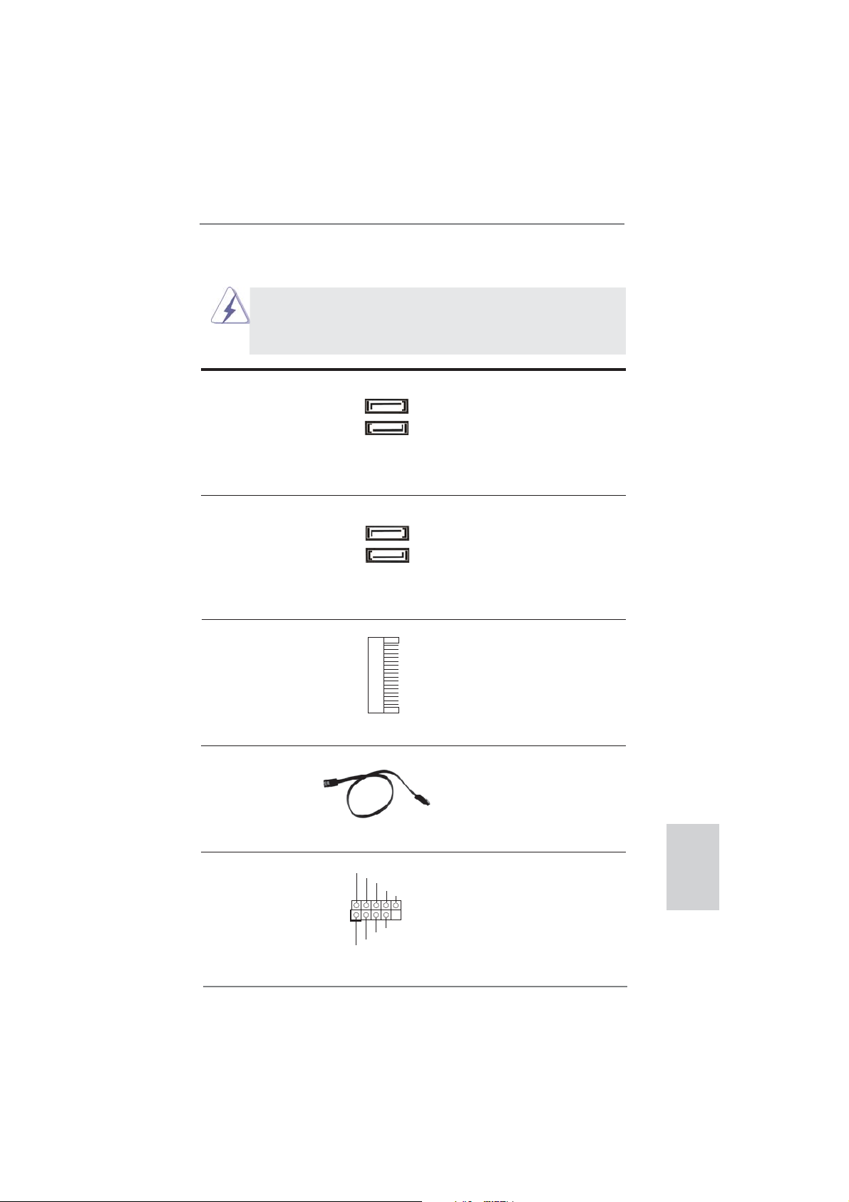
Serial ATA2 Connectors These two Serial ATA2 (SATA2)
(SATA_2: see p.2, No. 4)
(SATA_3: see p.2, No. 1)
connectors support SATA data
cables for internal storage
devices. The current SATA2
interface allows up to 3.0 Gb/s
SATA_2
SATA_3
data transfer rate.
Serial ATA3 Connectors These two Serial ATA3 (SATA3)
(SATA3_0: see p.2, No. 3)
(SATA3_1: see p.2, No. 2)
connectors support SATA data
cables for internal storage
devices. The current SATA3
interface allows up to 6.0 Gb/s
SATA3_0
SATA3_1
data transfer rate.
mSATA Connector This mSATA connector can be
(see p.3, No. 23)
used to connect a Solid-State
Drive (SSD) for an internal
storage device. The current
mSATA interface allows up to
3.0 Gb/s data transfer rate.
Serial ATA (SATA) Either end of the SATA data
Data Cable cable can be connected to the
(Optional)
SATA / SATA2 / SATA3 hard
disk or the SATA2 / SATA3
connector on this motherboard.
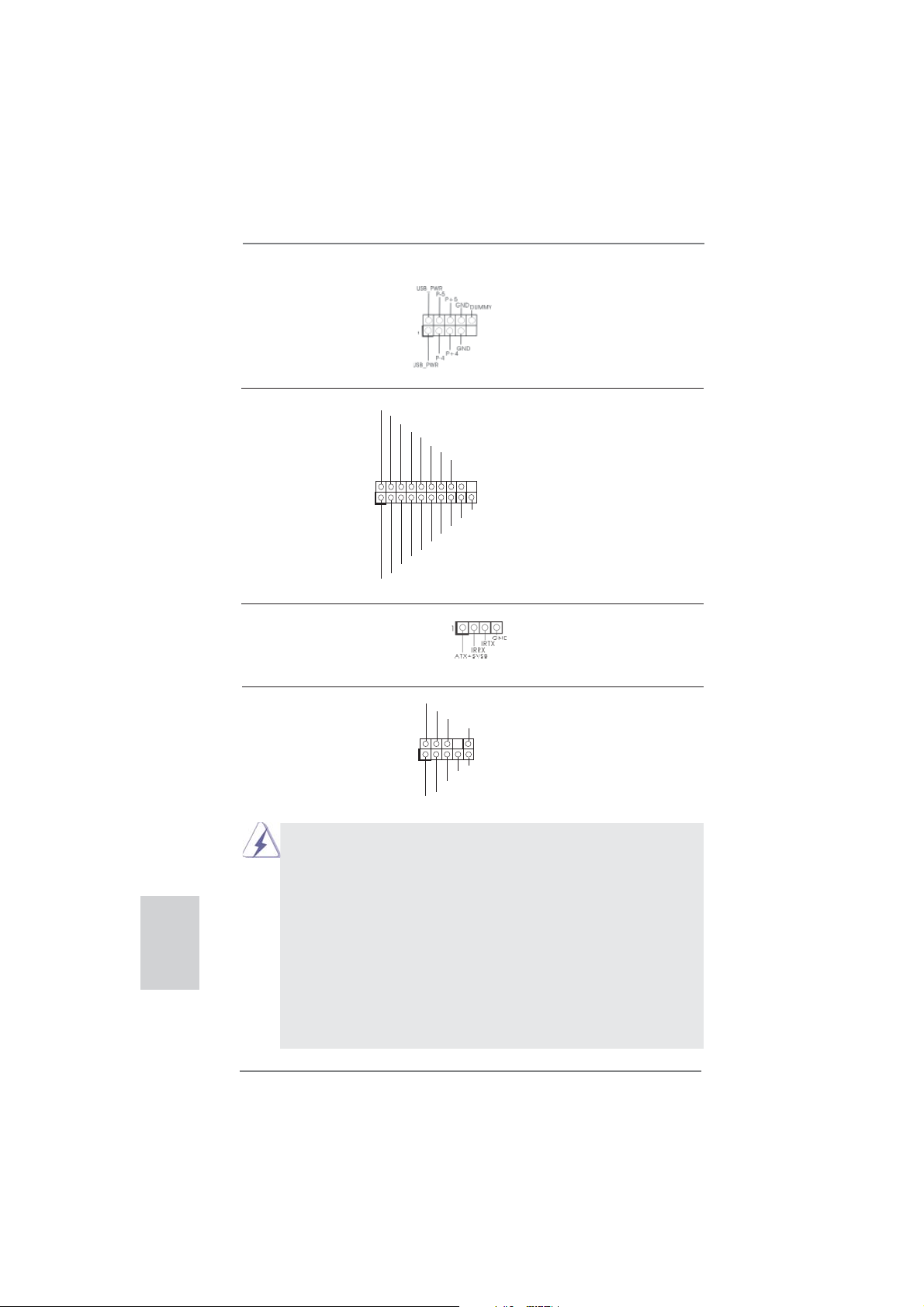
USB 2.0 Headers Besides two default USB 2.0
(9-pin USB2_3)
(see p.2, No. 5)
ports on the I/O panel, there are
two USB 2.0 headers on this
motherboard. Each USB 2.0
header can support two USB 2.0
ports.
1
USB_PWR
P-3
P-2
USB_PWR
P+3
P+2
GND
GND
DUMMY
ASRock Z77E-ITX Motherboard
English
27
Page 28
(9-pin USB4_5)
(see p.2, No. 6)
English
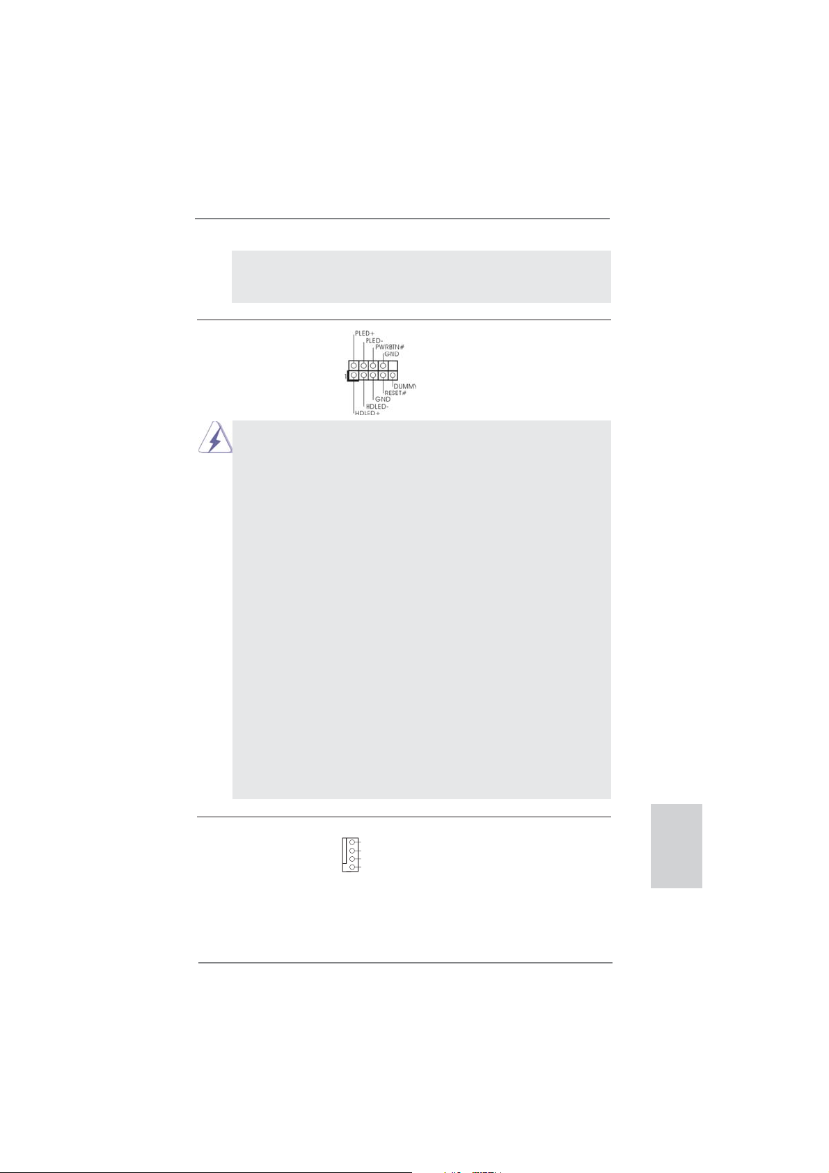
USB 3.0 Header Besides four default USB 3.0
(19-pin USB3_3_4)
(see p.2, No. 8)
ports on the I/O panel, there is
one USB 3.0 header on this
motherboard. This USB 3.0
IntA_P0_D+
IntA_P0_D-
GND
IntA_P0_SSTX+
IntA_P0_SSTX-
GND
IntA_P0_SSRX+
IntA_P0_SSRX-
Vbus
header can support two USB 3.0
ports.
1
GND
IntA_P1_D-
IntA_P1_D+
IntA_P1_SSRX+
GND
IntA_P1_SSTX-
IntA_P1_SSTX+
Vbus
IntA_P1_SSRX-
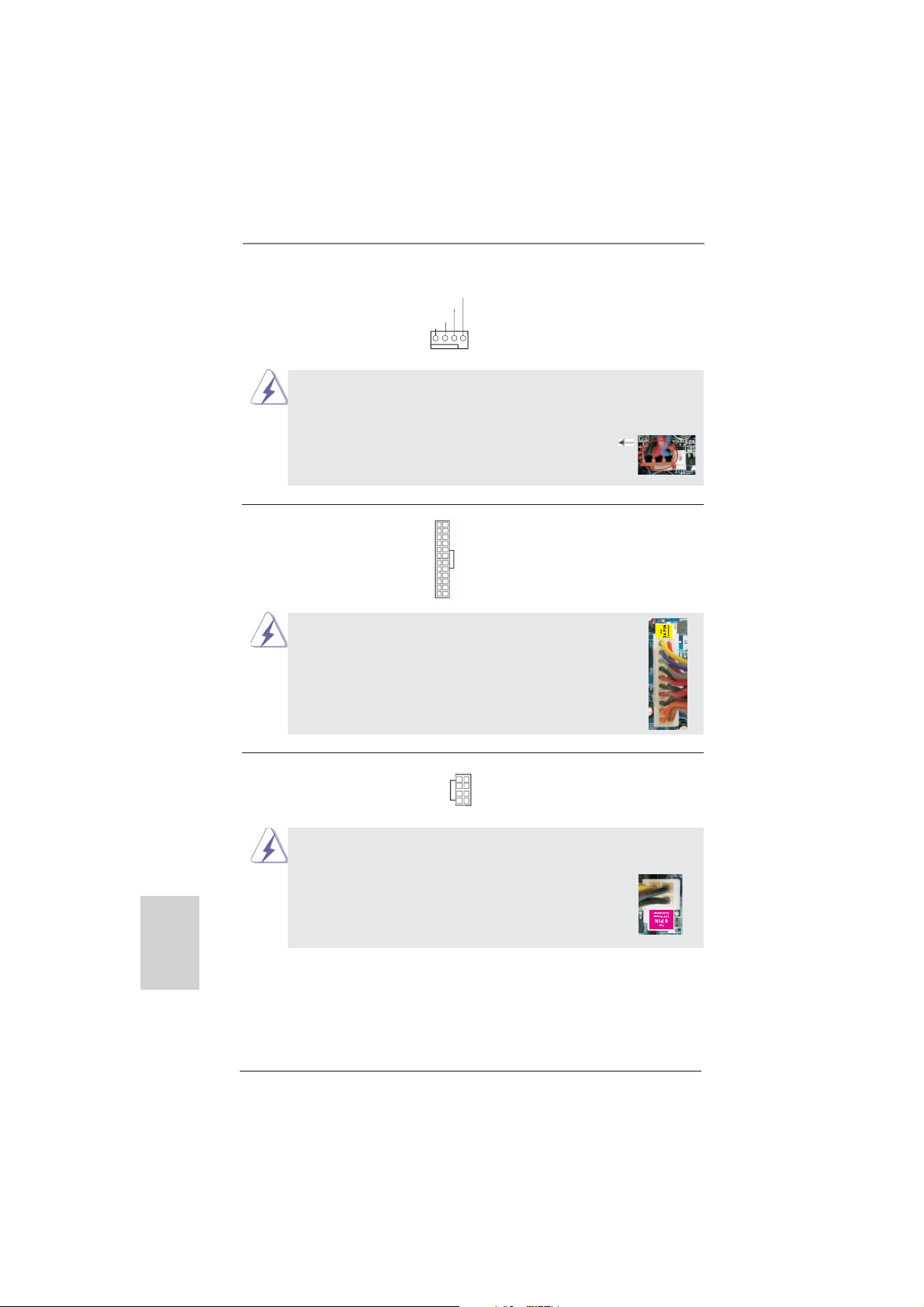
Consumer Infrared Module Header This header can be used to
(4-pin CIR1)
(see p.2 No. 7)
Front Panel Audio Header This is an interface for front
(9-pin HD_AUDIO1)
(see p.2, No. 19)
control of audio devices.
connect the remote
controller receiver.
GND
PRESENCE#
panel audio cable that allows
MIC_RET
OUT_RET
convenient connection and
1
1. High Defi nition Audio supports Jack Sensing, but the panel wire on the
chassis must support HDA to function correctly. Please follow the
instruction in our manual and chassis manual to install your system.
2. If you use AC’97 audio panel, please install it to the front panel audio
header as below:
A. Connect Mic_IN (MIC) to MIC2_L.
B. Connect Audio_R (RIN) to OUT2_R and Audio_L (LIN) to OUT2_L.
C. Connect Ground (GND) to Ground (GND).
D. MIC_RET and OUT_RET are for HD audio panel only. You don’t need
to connect them for AC’97 audio panel.
E. To activate the front mic.
For Windows
®
XP / XP 64-bit OS:
Select “Mixer”. Select “Recorder”. Then click “FrontMic”.
MIC2_R
MIC2_L
J_SENSE
OUT2_R
OUT2_L
28
ASRock Z77E-ITX Motherboard
Page 29
For Windows® 7 / 7 64-bit / VistaTM / VistaTM 64-bit OS:
Go to the “FrontMic” Tab in the Realtek Control panel. Adjust
“Recording Volume”.
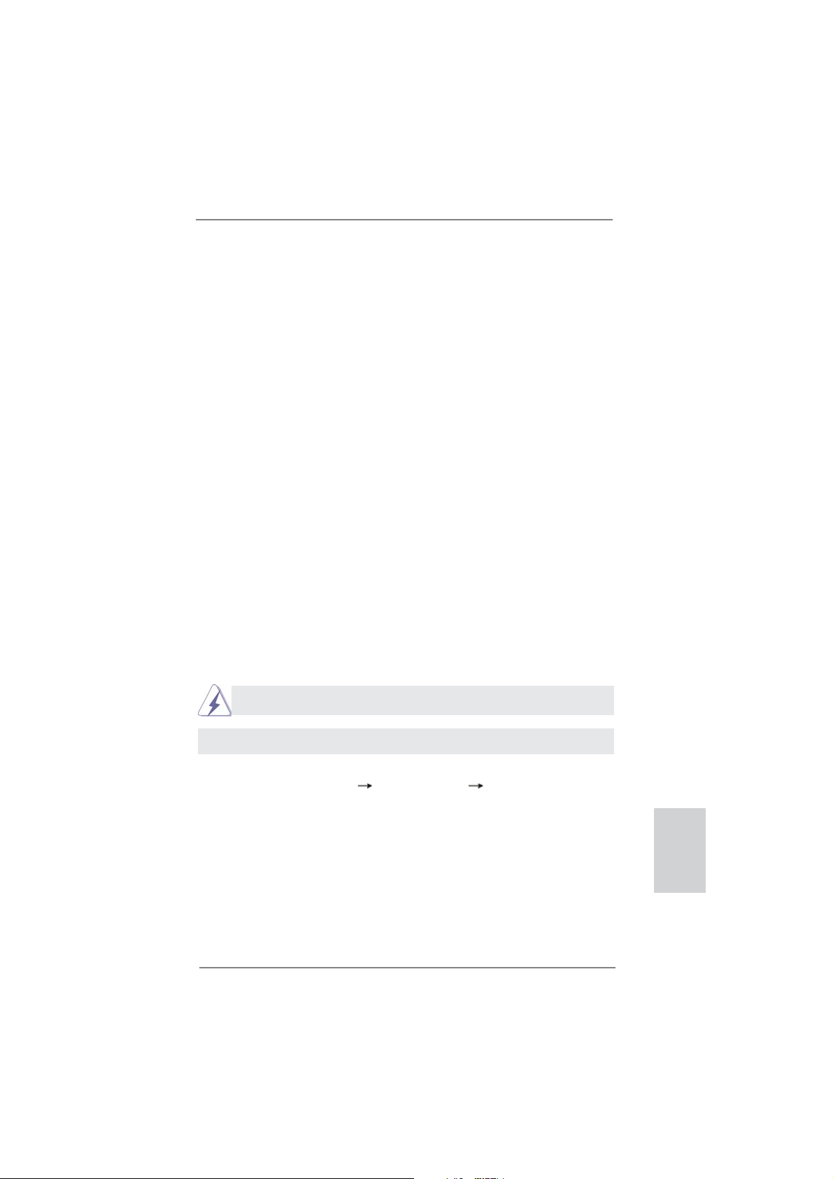
System Panel Header This header accommodates
(9-pin PANEL1)
(see p.2, No. 17)
several system front panel
functions.
Connect the power switch, reset switch and system status indicator on the
chassis to this header according to the pin assignments below. Note the
positive and negative pins before connecting the cables.
PWRBTN (Power Switch):
Connect to the power switch on the chassis front panel. You may confi gure
the way to turn off your system using the power switch.
RESET (Reset Switch):
Connect to the reset switch on the chassis front panel. Press the reset
switch to restart the computer if the computer freezes and fails to perform a
normal restart.
PLED (System Power LED):
Connect to the power status indicator on the chassis front panel. The LED
is on when the system is operating. The LED keeps blinking when the system is in S1/S3 sleep state. The LED is off when the system is in S4 sleep
state or powered off (S5).
HDLED (Hard Drive Activity LED):
Connect to the hard drive activity LED on the chassis front panel. The LED
is on when the hard drive is reading or writing data.
The front panel design may differ by chassis. A front panel module mainly
consists of power switch, reset switch, power LED, hard drive activity LED,
speaker and etc. When connecting your chassis front panel module to this
header, make sure the wire assignments and the pin assign-ments are
matched correctly.
Chassis Fan Connector Please connect the chassis fan
(4-pin CHA_FAN1)
(see p.2, No. 13)
cable to the connector and
match the black wire to the
GND
+12V
CHA_FAN_SPEED
FAN_SPEED_CONTROL
ground pin.
29
ASRock Z77E-ITX Motherboard
English
Page 30
CPU Fan Connectors Please connect the CPU fan
(4-pin CPU_FAN1)
(see p.2, No. 10)
cable to the connector and
match the black wire to the
ground pin.
FAN_SPEED_CONTROL
CPU_FAN_SPEED
+12V
GND
1 2 3 4
Though this motherboard provides 4-Pin CPU fan (Quiet Fan) support, the 3-Pin
CPU fan still can work successfully even without the fan speed control function.
If you plan to connect the 3-Pin CPU fan to the CPU fan connector on this
motherboard, please connect it to Pin 1-3.
Pin 1-3 Connected
3-Pin Fan Installation
English
ATX Power Connector Please connect an ATX power
(24-pin ATXPWR1)
(see p.2, No. 16)
supply to this connector.
Though this motherboard provides 24-pin ATX power connector,
12 124
13
12
it can still work if you adopt a traditional 20-pin ATX power supply.
To use the 20-pin ATX power supply, please plug your
power supply along with Pin 1 and Pin 13.
20-Pin ATX Power Supply Installation
ATX 12V Power Connector Please connect an ATX 12V
(8-pin ATX12V1)
(see p.2, No. 22)
power supply to this connector.
5 1
8 4
1
Though this motherboard provides 8-pin ATX 12V power connector, it can still work
if you adopt a traditional 4-pin ATX 12V power supply. To use the 4-pin ATX power
supply, please plug your power supply along with Pin 1 and Pin 5.
4-Pin ATX 12V Power Supply Installation
5 1
8 4
24
13
30
ASRock Z77E-ITX Motherboard
Page 31
2.11 Driver Installation Guide
To install the drivers to your system, please insert the support CD to your optical
drive fi rst. Then, the drivers compatible to your system can be auto-detected and
listed on the support CD driver page. Please follow the order from up to bottom side
to install those required drivers. Therefore, the drivers you install can work properly.
2.12 Installing Windows® 7 / 7 64-bit With RAID Functions
If you want to install Windows® 7 / 7 64-bit on your SATA / SATA2 / SATA3 HDDs
with RAID functions, please refer to the document at the following path in the
Support CD for detailed procedures:
..\ RAID Installation Guide
2.13 Installing Windows® 7 / 7 64-bit / Vista
TM
/ Vista
TM
64-bit / XP /
XP 64-bit Without RAID Functions
If you want to install Windows® 7 / 7 64-bit / VistaTM / VistaTM 64-bit / XP / XP 64bit OS on your SATA / SATA2 / SATA3 HDDs without RAID functions, please follow
below procedures according to the OS you install.
2.13.1 Installing Windows® XP / XP 64-bit Without RAID Functions
If you want to install Windows® XP / XP 64-bit OS on your SATA / SATA2 / SATA3
HDDs without RAID functions, please follow below steps.
AHCI mode is not supported under Windows® XP / XP 64-bit.
Using SATA / SATA2 / SATA3 HDDs without NCQ function
STEP 1: Set Up UEFI.
A. Enter UEFI SETUP UTILITY Advanced screen Storage Confi guration.
B. Set the option “SATA Mode Selection” to [IDE].
STEP 2: Install Windows® XP / XP 64-bit OS on your system.
English
ASRock Z77E-ITX Motherboard
31
Page 32

2.13.2 Installing Windows® 7 / 7 64-bit / Vista
TM
/ Vista
TM
64-bit
Without RAID Functions
If you want to install Windows® 7 / 7 64-bit / VistaTM / VistaTM 64-bit OS on your SATA
/ SATA2 / SATA3 HDDs without RAID functions, please follow below steps.
Using SATA / SATA2 / SATA3 HDDs without NCQ function
STEP 1: Set Up UEFI.
A. Enter UEFI SETUP UTILITY Advanced screen Storage Confi guration.
B. Set the option “SATA Mode Selection” to [IDE].
STEP 2: Install Windows
system.
Using SATA / SATA2 / SATA3 HDDs with NCQ function
STEP 1: Set Up UEFI.
A. Enter UEFI SETUP UTILITY Advanced screen Storage Confi guration.
B. Set the option “SATA Mode Selection” to [AHCI].
STEP 2: Install Windows
system.
®
7 / 7 64-bit / VistaTM / VistaTM 64-bit OS on your
®
7 / 7 64-bit / VistaTM / VistaTM 64-bit OS on your
English
32
ASRock Z77E-ITX Motherboard
Page 33

3. BIOS Information
The Flash Memory on the motherboard stores BIOS Setup Utility. When you start up
the computer, please press <F2> or <Del> during the Power-On-Self-Test (POST)
to enter BIOS Setup utility; otherwise, POST continues with its test routines. If you
wish to enter BIOS Setup after POST, please restart the system by pressing <Ctl>
+ <Alt> + <Delete>, or pressing the reset button on the system chassis. The BIOS
Setup program is designed to be user-friendly. It is a menu-driven program, which
allows you to scroll through its various sub-menus and to select among the predetermined choices. For the detailed information about BIOS Setup, please refer to the
User Manual (PDF fi le) contained in the Support CD.
4. Software Support CD information
®
This motherboard supports various Microsoft
64-bit / VistaTM / Vista
motherboard contains necessary drivers and useful utilities that will enhance motherboard features. To begin using the Support CD, insert the CD into your CD-ROM
drive. It will display the Main Menu automatically if “AUTORUN” is enabled in your
computer. If the Main Menu does not appear automatically, locate and double-click
on the fi le “ASSETUP.EXE” from the BIN folder in the Support CD to display the
menus.
TM
64-bit / XP / XP 64-bit. The Support CD that came with the
Windows® operating systems: 7 / 7
ASRock Z77E-ITX Motherboard
English
33
Page 34

1. Einführung
Wir danken Ihnen für den Kauf des ASRock Z77E-ITX Motherboard, ein zuverlässiges Produkt, welches unter den ständigen, strengen Qualitätskontrollen von ASRock
gefertigt wurde. Es bietet Ihnen exzellente Leistung und robustes Design, gemäß
der Verpflichtung von ASRock zu Qualität und Halbarkeit. Diese Schnellinstallationsanleitung führt in das Motherboard und die schrittweise Installation ein. Details
über das Motherboard fi nden Sie in der Bedienungsanleitung auf der Support-CD.
Da sich Motherboard-Spezifi kationen und BIOS-Software verändern können,
kann der Inhalt dieses Handbuches ebenfalls jederzeit geändert werden. Für
den Fall, dass sich Änderungen an diesem Handbuch ergeben, wird eine neue
Version auf der ASRock-Website, ohne weitere Ankündigung, verfügbar sein.
Die neuesten Grafi kkarten und unterstützten CPUs sind auch auf der ASRock-
Website aufgelistet.
ASRock-Website: http://www.asrock.com
Wenn Sie technische Unterstützung zu Ihrem Motherboard oder spezifi sche
Informationen zu Ihrem Modell benötigen, besuchen Sie bitte unsere Webseite:
www.asrock.com/support/index.asp
1.1 Kartoninhalt
ASRock Z77E-ITX Motherboard
(Mini-ITX-Formfaktor: 17.0 cm x 17.0 cm; 6.7 Zoll x 6.7 Zoll)
ASRock Z77E-ITX Schnellinstallationsanleitung
ASRock Z77E-ITX Support-CD
Zwei Serial ATA (SATA) -Datenkabel (optional)
Ein ASRock 2,4 GHz-Wi-Fi-Antenne (optional)
Ein DVI-zu-D-Sub-Umwandler (optional)
Ein I/O Shield
Deutsch
34
ASRock erinnert...
Zur besseren Leistung unter Windows® 7 / 7, 64 Bit / Vista
64 Bit empfehlen wir, die Speicherkonfi guration im BIOS auf den AHCI-
Modus einzustellen. Hinweise zu den BIOS-Einstellungen fi nden Sie in
der Bedienungsanleitung auf der mitgelieferten CD.
TM
/ VistaTM
ASRock Z77E-ITX Motherboard
Page 35

1.2 Spezifikationen
Plattform - Mini-ITX-Formfaktor: 17.0 cm x 17.0 cm; 6.7 Zoll x 6.7 Zoll
- Hochwertiges Gold-Kondensatordesign (100 % hochwertige
japanische Fertigung leitfähiger Polymerkondensatoren)
CPU - Unterstützt Intel
und 2ten Generation im LGA1155-Package
- Digi Power-Design
- 6 + 2-Stromphasendesign
- Unterstützt Intel
- Unterstützt freigegebene CPU der K-Serie
- Unterstützt Hyper-Threading-Technologie
(siehe VORSICHT 1)
- Unterstützt Intel® Rapid Start Technology und Smart
Connect Technology mit Intel
Chipsatz - Intel® Z77
Speicher - Dual-Kanal DDR3 Speichertechnologie (siehe VORSICHT 2)
- 2 x Steckplätze für DDR3
- Unterstützt DDR3 2800+(OC)/2400(OC)/2133(OC)/1866
(OC)/1600/1333/1066 non-ECC, ungepufferter Speicher
- Max. Kapazität des Systemspeichers: 16GB
(siehe VORSICHT 3)
- Unterstützt Intel
Erweiterungs- - 1 x PCI Express 3.0 x16-Steckplätze (PCIE1: x16-Modus)
steckplätze (siehe VORSICHT 4)
* PCIE 3.0 wird nur mit Intel
unterstützt. Mit Intel® Sandy Bridge-Prozessor wird nur
PCIE 2.0 unterstützt.
- 1 x mini-PCI-Express-Steckplatz: Für Wi-Fi-Modul
Onboard-VGA * Integrierte Intel
Ausgänge können nur durch GPU-integrierte Prozessoren
unterstützt werden.
- Unterstützt hochaufl ösende integrierte Intel®-Grafi klösungen:
Intel® Quick-Sync-Video 2.0, Intel® InTruTM 3D, Intel® Clear Video-Technik (HD), Intel® InsiderTM, Intel® HD Graphics
2500/4000
- Pixel Shader 5.0, DirectX 11 mit Intel
Pixel Shader 4.1, DirectX 10.1 mit Intel® Sandy Bridge Prozessor
- Maximal gemeinsam genutzter Speicher 1760MB
(siehe VORSICHT 5)
®
CoreTM i7- / i5- / i3-Prozessoren der 3ten
®
Turbo Boost 2.0-Technologie
®
Ivy Bridge-Prozessor
®
Extreme Memory Profi le (XMP)1.3/1.2
®
Ivy Bridge-Prozessor
®
HD-Grafi kdarstellungen und die VGA-
®
Ivy Bridge-Prozessor,
Deutsch
ASRock Z77E-ITX Motherboard
35
Page 36

Deutsch
36
- Multi VGA-Ausgangsoptionen: DVI, HDMI, DisplayPort
sowie D-Sub mit DVI-zu-D-Sub-Konverter
(siehe VORSICHT 6)
- Unterstützt HDMI 1.4a mit einer maximalen Aufl ösung von
1920 x 1200 bei 60 Hz
- Unterstützt DVI mit einer maximalen Aufl ösung von 1920 x
1200 bei 60 Hz
- Unterstützt DisplayPort mit einer maximalen Aufl ösung von
2560 x 1600 bei 60 Hz
- Unterstützt D-Sub mit einer maximalen Aufl ösung von
2048 x 1536 bei 75 Hz
- Unterstützt Auto Lip Sync, Deep Color (12bpc), xvYCC und
HBR (High Bit Rate-Audio) mit HDMI (kompatibler HDMI Bildschirm erforderlich) (siehe VORSICHT 7)
- Unterstützt HDCP-Funktion mit DVI-, HDMI- und
DisplayPort-Ports
- Unterstutzt 1080p Blu-ray (BD) / HD-DVD-Wiedergabe mit
DVI-, HDMI- und DisplayPort-Ports
Audio - 7.1
CH HD Audio mit dem Inhalt Schutz
(Realtek ALC898 Audio Codec)
- Premium Blu-ray-Audio-Unterstützung
- Unterstützt THX TruStudio
TM
LAN - PCIE x1 Gigabit LAN 10/100/1000 Mb/s
- Broadcom BCM57781
- Unterstützt Wake-On-LAN
- Unterstützt energieeffi zientes Ethernet 802.3az
- Unterstützt PXE
Wireless LAN 802.11n-Wi-Fi-Modul
- 300 MBit/s – IEEE 802.11n / 54 MBit/s – IEEE 802.11g /
11 MBit/s – IEEE 802.11b
- Unterstützt Stationsmodus (Infrastruktur- und Ad-hoc Modus)
E/A-Anschlüsse I/O Panel
an der Rückseite - 2 x Antennenports
- 1 x PS/2-Tastaturanschluss/Mausanschluss
- 1 x DVI-I port
- 1 x HDMI port
- 1 x DisplayPort
- 1 x optischer SPDIF-Ausgang
- 2 x Standard-USB 2.0-Anschlüsse
- 1 x eSATA2-Anschluss
- 4 x Standard-USB 3.0-Anschlüsse
ASRock Z77E-ITX Motherboard
Page 37

- 1 x RJ-45 LAN Port mit LED (ACT/LINK LED und SPEED
LED)
- 1 x CMOS löschen-Schalter mit LED
- HD Audiobuchse: Lautsprecher hinten / Mitte / Bass /
Audioeingang / Lautsprecher vorne / Mikrofon
(siehe VORSICHT 8)
SATA3 - 2 x SATA 3-Anschlüsse (6,0 Gb/s); unterstützt RAID- (RAID 0,
RAID 1, RAID 5, RAID 10, Intel Rapid Storage und Intel
Smart Response-Technologie), NCQ-, AHCI-und Hot Plug
Funktionen
USB3.0 - 2 x USB 3.0-Ports an der Rückseite durch Intel
®
Z77,
unterstützt USB 1.0/2.0/3.0 mit bis zu 5 Gb/s
- 2 x USB 3.0-Ports an der Rückseite durch ASMedia
ASM1042, unterstützt USB 1.0/2.0/3.0 mit bis zu 5 Gb/s
- 1 x USB 3.0-Header (unterstützt zwei USB 3.0-Ports) an
der Vorderseite durch Intel
®
Z77, unterstützt USB 1.0/2.0/3.0
mit bis zu 5 Gb/s
Anschlüsse - 2 x SATA2 3,0 GB/s-Anschlüsse, unterstützen RAID- (RAID
0, RAID 1, RAID 5, RAID 10, Intel Rapid Storage und Intel
Smart Response-Technologie), NCQ-, AHCI-und Hot Plug
Funktionen
- 1 x 3 GB/s-mSATA-Anschluss (Solid-State Drive-Anschluss),
unterstützt RAID (RAID 0, RAID 1, RAID 5, RAID 10, Intel
Rapid Storage und Intel Smart Response Technology),
NCQ-, AHCI-Funktionen und Full-size mini-PCI-Express Modul
- 2 x SATA3 6,0 GB/s-Anschlüsse
- 1 x
Consumer Infrared-Modul-Header
- CPU/Gehäuse lüfter-Anschluss
- 24-pin ATX-Netz-Header
- 8-pin anschluss für 12V-ATX-Netzteil
- Anschluss für Audio auf der Gehäusevorderseite
- 2 x USB 2.0-Anschlüsse (Unterstützung 4 zusätzlicher
USB 2.0-Anschlüsse)
- 1 x USB 3.0-Anschlüsse (Unterstützung 2 zusätzlicher
USB 3.0-Anschlüsse)
BIOS - 64Mb AMIs Legal BIOS UEFI mit GUI-Unterstützung
- Unterstützung für “Plug and Play”
- ACPI 1.1-Weckfunktionen
- JumperFree-Modus
- SMBIOS 2.3.1
- CPU Core, IGPU, DRAM, VCCSA Stromspannung
ASRock Z77E-ITX Motherboard
Deutsch
37
Page 38
Deutsch
Multianpassung
CD d’assistance - Treiber, Dienstprogramme, Antivirussoftware (Probeversion),
CyberLink MediaEspresso 6.5-Testversion, ASRock
MAGIX-Multimedia-Suite - OEM
Einzigartige - ASRock Extreme Tuning Utility (AXTU) (siehe VORSICHT 9)
Eigenschaft - ASRock Sofortstart
- ASRock Instant Flash (siehe VORSICHT 10)
- ASRock APP Charger (siehe VORSICHT 11)
- ASRock SmartView (siehe VORSICHT 12)
- ASRock XFast USB (siehe VORSICHT 13)
- ASRock XFast LAN (siehe VORSICHT 14)
- ASRock XFast RAM (siehe VORSICHT 15)
- ASRock Crashless BIOS (siehe VORSICHT 16)
- ASRock OMG (Online Management Guard)
(siehe VORSICHT 17)
- ASRock Internet Flash (siehe VORSICHT 18)
- Lucid Virtu Universal MVP (siehe VORSICHT 19)
* Lucid Virtu Universal MVP kann nur durch GPU-integrierte
Prozessoren unterstützt werden.
- Hybrid Booster:
- Schrittloser CPU-Frequenz-Kontrolle
(siehe VORSICHT 20)
- ASRock U-COP (siehe VORSICHT 21)
- Boot Failure Guard (B.F.G. – Systemstartfehlerschutz)
- Gute Nacht-LED
Hardware Monitor - Überwachung der CPU-Temperatur
- Motherboardtemperaturerkennung
- Drehzahlmessung für CPU lüfter
- Drehzahlmessung für Gehäuse lüfter
- Geräuscharmer CPU-/Gehäuselüfter (ermöglicht die au
tomatische Anpassung der Gehäuselüftergeschwindigkeit
durch CPU-Temperatur)
- Mehrstufi ge Geschwindigkeitssteuerung für CPU/Gehäuse
lüfter
- Spannungsüberwachung: +12V, +5V, +3.3V, Vcore
®
Betriebssysteme - Unterstützt Microsoft
Vista
TM
64-Bit / XP / XP 64-Bit (siehe VORSICHT 22)
Windows® 7 / 7 64-Bit / VistaTM /
Zertifi zierungen - FCC, CE, WHQL
- Gemäß Ökodesign-Richtlinie (ErP/EuP) (Stromversorgung
gemäß Ökodesign-Richtlinie (ErP/EuP) erforderlich)
(siehe VORSICHT 23)
38
ASRock Z77E-ITX Motherboard
Page 39

* Für die ausführliche Produktinformation, besuchen Sie bitte unsere Website:
http://www.asrock.com
WARNUNG
Beachten Sie bitte, dass Overclocking, einschließlich der Einstellung im BIOS,
Anwenden der Untied Overclocking-Technologie oder Verwenden von Overclocking Werkzeugen von Dritten, mit einem gewissen Risiko behaftet ist. Overclocking kann
sich nachteilig auf die Stabilität Ihres Systems auswirken oder sogar Komponenten
und Geräte Ihres Systems beschädigen. Es geschieht dann auf eigene Gefahr und
auf Ihre Kosten. Wir übernehmen keine Verantwortung für mögliche Schäden, die
aufgrund von Overclocking verursacht wurden.
VORSICHT!
1. Die Einstellung der “Hyper-Threading Technology”, fi nden Sie auf Seite
47 des auf der Support-CD enthaltenen Benutzerhandbuches beschrieben.
2. Dieses Motherboard unterstützt Dual-Kanal-Speichertechnologie. Vor
Implementierung der Dual-Kanal-Speichertechnologie müssen Sie die Installationsanleitung für die Speichermodule auf Seite 19 zwecks richtiger
Installation gelesen haben.
3. Durch Betriebssystem-Einschränkungen kann die tatsächliche Speichergröße weniger als 4 GB betragen, da unter Windows
etwas Speicher zur Nutzung durch das System reserviert wird. Unter
Windows® OS mit 64-Bit-CPU besteht diese Einschränkung nicht. Sie
können ASRock XFast RAM zur Nutzung des Speichers, den Windows
nicht verwenden kann, einsetzen.
4. Unterstützt nur der PCIE1-Steckplatz Geschwindigkeiten der 3ten Generation. Damit Sie PCI Express mit der Geschwindigkeit der 3ten Generation nutzen können, müssen Sie einen Ivy Bridge-Prozessor installieren.
Wenn Sie einen Sandy Bridge-Prozessor installieren, läuft PCI Express
nur bei der Geschwindigkeit der 2ten Generation.
5. Die Maximalspeichergröße ist von den Chipshändler defi niert und umge-
tauscht. Bitte überprüfen Sie Intel
®
website für die neuliche Information.
6. Sie können nur die Nutzung von zwei von drei Bildschirmen auswählen.
Die DVI-, HDMI- und DisplayPort-Bildschirme können nicht gleichzeitig
aktiviert werden. Zudem kann der DVI-Port mit DVI-zu-HDMI-Adapter
dieselben Funktionen wie der HDMI-Port unterstützen.
7. xvYCC und Deep Color werden nur unter Windows
stützt. Der Deep Color-Modus wird nur aktiviert, wenn der Bildschirm
12bpc in EDID unterstützt. HBR wird unter Windows
64 Bit / VistaTM unterstützt.
8. Der Mikrofoneingang dieses Motherboards unterstützt Stereo- und MonoModi. Der Audioausgang dieses Motherboards unterstützt 2-Kanal-,
4-Kanal-, 6-Kanal- und 8-Kanal-Modi. Stellen Sie die richtige Verbindung
anhand der Tabelle auf Seite 4 her.
®
7 / Vista™ / XP
®
7 64-Bit / 7 unter-
®
7 64 Bit / 7 / VistaTM
®
Deutsch
ASRock Z77E-ITX Motherboard
39
Page 40

Deutsch
9. ASRock Extreme Tuning Utility (AXTU) ist ein Alles-in-einem-
Werkzeug zur Feineinstellung verschiedener Systemfunktionen an
einer benutzerfreundlichen Schnittstelle; diese beinhaltet HardwareÜberwachung, Lüftersteuerung, Übertaktung, OC DNA und IES. Über die
Hardware-Überwachung können Sie die Hauptsystemdaten einsehen.
Die Lüftersteuerung zeigt Ihnen zur Anpassung Lüftergeschwindigkeit
und Temperatur an. Bei der Übertaktung können Sie die CPU-Frequenz
zur Erzielung optimaler Systemleistung übertakten. OC DNA ermöglicht
Ihnen die Speicherung Ihrer OC-Einstellungen als Profi l, welches Sie
mit Freunden teilen können. Ihre Freunde können das OC-Profi l dann
in ihrem System laden und so die gleichen OC-Einstellungen erzielen.
Per IES (Intelligent Energy Saver) kann der Spannungsregulator bei
Inaktivität der CPU-Kerne die Anzahl an Ausgangsphasen zur Steigerung
der Effi zienz reduzieren – ohne die Rechenleistung zu beeinträchtigen.
Hinweise zur Bedienung der ASRock Extreme Tuning Utility (AXTU)
fi nden Sie auf unserer Webseite.
ASRock-Webseite: http://www.asrock.com
10. ASRock Instant Flash ist ein im Flash-ROM eingebettetes BIOS-Flash-
Programm. Mithilfe dieses praktischen BIOS-Aktualisierungswerkzeugs
können Sie das System-BIOS aktualisieren, ohne dafür zuerst Betriebssysteme wie MS-DOS oder Windows® aufrufen zu müssen. Mit diesem
Programm bekommen Sie durch Drücken der <F6>-Taste während des
POST-Vorgangs oder durch Drücken der <F2>-Taste im BIOS-SetupMenü Zugang zu ASRock Instant Flash. Sie brauchen dieses Werkzeug
einfach nur zu starten und die neue BIOS-Datei auf Ihrem USB-Flash-
Laufwerk, Diskettenlaufwerk oder der Festplatte zu speichern, und schon
können Sie Ihr BIOS mit nur wenigen Klickvorgängen ohne Bereitstellung
einer zusätzlichen Diskette oder eines anderen komplizierten Flash-Pro-
gramms aktualisieren. Achten Sie darauf, dass das USB-Flash-Laufwerk
oder die Festplatte das Dateisystem FAT32/16/12 benutzen muss.
11. Wenn Sie nach einer schnelleren, weniger eingeschränkten Möglich-
keit zur Aufl adung Ihrer Apple-Geräte (z. B. iPhone/iPad/iPod touch)
suchen, bietet ASRock Ihnen eine wunderbare Lösung – den ASRock
APP Charger. Installieren Sie einfach den ASRock APP Charger-Treiber;
dadurch lädt sich Ihr iPhone wesentlich schneller über einen Computer-
auf – genaugenommen bis zu 40 % schneller als zuvor. Der ASRock APP
Charger ermöglicht Ihnen die schnelle Aufl adung mehrerer Apple-Geräte
gleichzeitig; der Ladevorgang wird sogar dann fortgesetzt, wenn der PC
den Ruhezustand (S1), Suspend to RAM-Modus (S3) oder Tiefschlafmo-
dus (S4) aufruft oder ausgeschaltet wird (S5). Nach der Installation des
APP Charger-Treibers können Sie im Handumdrehen das großartigste
Ladeerlebnis überhaupt genießen. ASRock-Webseite: http://www.asrock.
com/Feature/AppCharger/index.asp
40
ASRock Z77E-ITX Motherboard
Page 41

12. SmartView, eine neue Internetbrowserfunktion, ist eine intelligente IE-
Startseite, die meist besuchte Internetseiten, Ihren Browserverlauf,
Facebook-Freunde und Nachrichten in Echtzeit miteinander kombiniert:
In einer speziellen Ansicht, die das Internet noch angenehmer und aufregender macht. ASRock-Motherboards werden exklusiv mit der SmartView-Software geliefert, die auch dafür sorgt, dass Sie immer mit Ihren
Freunden in Verbindung bleiben. Die SmartView-Funktionen können Sie
mit den Windows®-Betriebssystemen 7 / 7, 64 Bit / VistaTM / VistaTM 64 Bit
und dem Internet Explorer ab Version 8 nutzen.
ASRock-Website: http://www.asrock.com/Feature/SmartView/index.asp
13. ASRocks XFast USB dient der Steigerung der Leistungsfähigkeit Ihrer
USB-Speichergeräte. Die Leistung kann je nach Eigenschaften des
Gerätes variieren.
14. ASRock XFast LAN bietet einen schnelleren Internetzugang mit den
nachfolgenden Vorteilen. LAN-Anwendungspriorisierung: Hiermit kon-
fi gurieren Sie auf ideale Weise Ihre Anwendungspriorität und/oder fügen
neue Programme hinzu. Niedrigere Latenzzeit bei Spielen: Nach Einstel
lung einer höheren Online-Gamepriorität kann hiermit die Latenzzeit bei
Spielen herabgesetzt werden. Datenverkehrsgestaltung: Sie können
Youtube-Videos in HD anzeigen und gleichzeitig Dateien herunterladen.
Echtzeitanalyse Ihrer Daten: Über das Statusfenster können Sie schnell
ermitteln, welche Datenströme zur Zeit übertragen werden.
15. ASRock XFast RAM ist eine neue Funktion, die beim ASRock Extreme
Tuning Utility (AXTU) integriert ist. Sie ermöglicht die vollständige Nut-
zung des Speicherplatzes, der unter Windows®-Betriebssystemen mit
32-Bit-CPU nicht verwendet werden kann. ASRock XFast RAM verkürzt
die Ladezeit zuvor besuchter Webseiten, was das Surfen im Internet
mehr denn je beschleunigt. Auch die Arbeit mit Adobe Photoshop erfolgt
fünfmal schneller. Ein weiterer Vorteil von ASRock XFast RAM liegt in der
Reduzierung der Häufi gkeit des Zugriffs auf SSDs bzw. HDDs zur Verlän
gerung deren Lebenszeit.
16. ASRock Crashless BIOS ermöglicht Benutzern die Aktualisierung ihres
BIOS, ohne dass diese Fehler fürchten müssen. Falls während der BIOSAktualisierung ein Stromausfall auftritt, setzt ASRock Crashless BIOS
die BIOS-Aktualisierung automatisch fort, sobald die Stromversorgung
wiederhergestellt ist. Bitte beachten Sie, dass alle BIOS-Dateien zuerst
im Stammverzeichnis Ihres USB-Datenträgers platziert werden müssen.
Diese Funktion wird nur von USB 2.0-Ports unterstützt.
17. Mit OMG können Administratoren den Internetzugriff zu bestimmten
Zeiten sperren oder einschränken. Sie können zwischen [Täglich],
[Wochentag] und [Wochentage und Wochenende] auswählen, dann
legen Sie die Anfangs- und Endzeiten fest, zu denen anderen Nutzern
der Internetzugang gewährt werden soll. Damit OMG nicht von Nutzern
umgangen werden kann, dürfen Gästekonten keine Rechte zur Änderung
der Systemzeit eingeräumt werden.
Deutsch
ASRock Z77E-ITX Motherboard
41
Page 42

Deutsch
18. Die Internet Flash sucht nach verfügbaren UEFI-Aktualisierungen auf un-
seren Servern. Mit anderen Worten: Das System erkennt aktuellste UEFIFirmware auf unseren Servern automatisch und aktualisiert die GeräteFirmware ohne Zutun von Windows. Bitte beachten Sie, dass diese
Funktion nur mit DHCP-konfi gurierten Computern möglich ist.
19. Virtu Universal MVP beinhaltet die Basisfunktionen der Virtu Universal-
Technologie, die integrierte GPU und separate GPU zur Erzielung optimaler Funktionalität virtualisiert. Verfügt zudem über Virtual VsyncTM für
kompromisslose visuelle Qualität. Dank der zusätzlichen Vorzüge der
HyperFormance-Technologie verbessert Virtu Universal MVP die Spielleistung durch intelligente Reduzierung redundanter Rendering-Aufgaben
im Fluss zwischen CPU, GPU und Anzeigegerät.
20. Durch die ASRock ein/aus-Wiedergabetechnologie können Sie großar-
tige Klangerlebnisse von portablen Audiogeräten, wie z. B. MP3-Playern
oder Mobiltelefonen, an Ihrem PC genießen – selbst wenn der PC ausgeschaltet ist (oder sich im ACPI S5-Modus befi ndet)! Dieses Motherboard
wird zudem mit einem kostenlosen Audiokabel (3,5 mm, Klinke) (optional)
geliefert, was eine IT-Umgebung von höchster Benutzerfreundlichkeit
gewährleistet.
21. Wird eine Überhitzung der CPU registriert, führt das System einen au-
tomatischen Shutdown durch. Bevor Sie das System neu starten, prüfen
Sie bitte, ob der CPU-Lüfter am Motherboard richtig funktioniert, und
stecken Sie bitte den Stromkabelstecker aus und dann wieder ein. Um
die Wärmeableitung zu verbessern, bitte nicht vergessen, etwas Wärmel-
eitpaste zwischen CPU und Kühlkörper zu sprühen.
22. ASRock XFast RAM wird von Microsoft® Windows® XP / XP 64 Bit nicht
unterstützt. Intel® Smart Connect-Technologie und Intel® USB 3.0-Ports
wird von Microsoft® Windows® VistaTM / VistaTM 64 Bit / XP / XP 64 Bit
nicht unterstützt.
23. EuP steht für Energy Using Product und kennzeichnet die Ökodesign-
Richtlinie, die von der Europäischen Gemeinschaft zur Festlegung des Energieverbrauchs von vollständigen Systemen in Kraft gesetzt wurde. Gemäß
dieser Ökodesign-Richtlinie (EuP) muss der gesamte Netzstromverbrauch
von vollständigen Systemen unter 1,00 Watt liegen, wenn sie ausgeschaltet
sind. Um dem EuP-Standard zu entsprechen, sind ein EuP-fähiges Motherboard und eine EuP-fähige Stromversorgung erforderlich. Gemäß einer
Empfehlung von Intel muss eine EuP-fähige Stromversorgung dem Standard
entsprechen, was bedeutet, dass bei einem Stromverbrauch von 100 mA
die 5-Volt-Standby-Energieeffi zienz höher als 50% sein sollte. Für die Wahl
einer EuP-fähigen Stromversorgung empfehlen wir Ihnen, weitere Details
beim Hersteller der Stromversorgung abzufragen.
42
ASRock Z77E-ITX Motherboard
Page 43
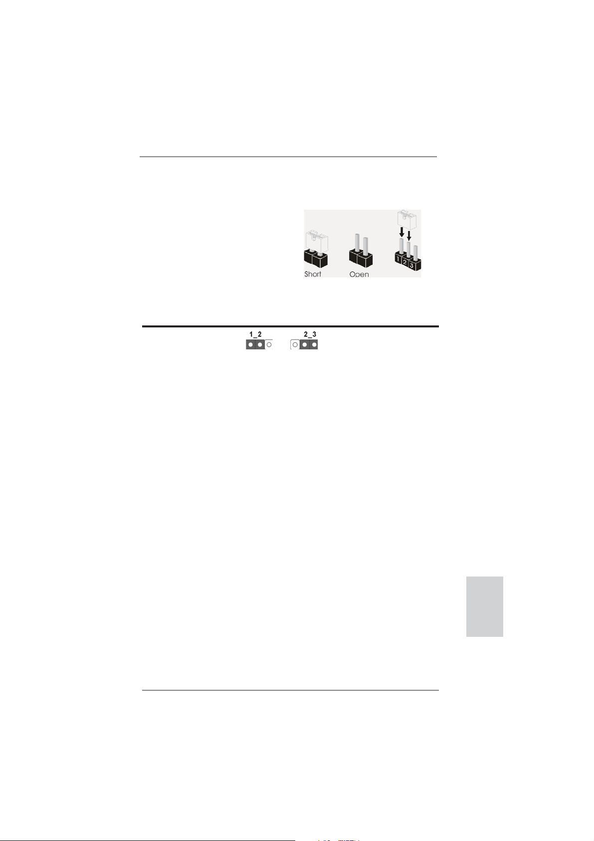
1.3 Einstellung der Jumper
Die Abbildung verdeutlicht, wie Jumper
gesetzt werden. Werden Pins durch
Jumperkappen verdeckt, ist der Jumper
“Gebrückt”. Werden keine Pins durch
Jumperkappen verdeckt, ist der Jumper
“Offen”. Die Abbildung zeigt einen 3-Pin
Jumper dessen Pin1 und Pin2 “Gebrückt” sind, bzw. es befi ndet sich eine
Jumper-Kappe auf diesen beiden Pins.
Jumper Einstellun Beschreibung
CMOS löschen
(CLRCMOS1, 3-Pin jumper)
(siehe S.2, No. 11)
Hinweis:
CLRCMOS1 ermöglicht Ihnen die Löschung der Daten im CMOS. Zum
Löschen und Zurücksetzen der Systemparameter auf die Standardeinrichtung
schalten Sie den Computer bitte aus und trennen das Netzkabel von der
Stromversorgung. Warten Sie 15 Sekunden, schließen Sie dann Pin2 und
Pin3 am CLRCMOS1 über einen Jumper fünf Sekunden lang kurz. Sie
sollten das CMOS allerdings nicht direkt nach der BIOS-Aktualisierung
löschen. Wenn Sie das CMOS nach Abschluss der BIOS-Aktualisierung
löschen müssen, fahren Sie zuerst das System hoch. Fahren Sie es dann
vor der CMOS-Löschung herunter. Bitte beachten Sie, dass Kennwort,
Datum, Uhrzeit, benutzerdefi niertes Profi l, 1394 GUID und MAC-Adresse
nur gelöscht werden, wenn die CMOS-Batterie entfernt wird.
DefaultEinstellung
CMOS
löschen
ASRock Z77E-ITX Motherboard
Deutsch
43
Page 44

1.4 Integrierte Header und Anschlüsse
Integrierte Header und Anschlüsse sind KEINE Jumper. Setzen Sie KEINE Jumperkappen auf diese Header und Anschlüsse. Wenn Sie Jumperkappen auf Header und Anschlüsse setzen, wird das Motherboard
unreparierbar beschädigt!
Deutsch
44
Seriell-ATA2-Anschlüsse Diese zwei Serial ATA2-
(SATA_2: siehe S.2 - No. 4)
(SATA_3: siehe S.2 - No. 1)
(SATA2-)Verbínder
unterstützten SATA-Datenkabel
für interne
Massenspeichergeräte. Die
SATA_2
SATA_3
aktuelle SATA2- Schnittstelle
ermöglicht eine
Datenübertragungsrate bis
3,0 Gb/s.
Seriell-ATA3-Anschlüsse Diese zwei Serial ATA3-
(SATA3_0: siehe S.2 - No. 3)
(SATA3_1: siehe S.2 - No. 2)
(SATA3-)Verbínder
unterstützten SATA-Datenkabel
SATA3_0
für interne
Massenspeichergeräte. Die
SATA3_1
aktuelle SATA3- Schnittstelle
ermöglicht eine
Datenübertragungsrate bis 6,0
Gb/s.
mSATA-Anschluss Dieser mSATA-Anschluss kann
(siehe S.3 - No. 23)
zum Anschließen einer Solid State Drive (SSD) als internes
Speichergerät genutzt werden.
Die aktuelle mSATA-Schnitt stelle erlaubt Datentransfer raten bis 3,0 Gb/s.
Serial ATA- (SATA-) SJedes Ende des SATA
Datenkabel Datenkabels kann an die SATA
(Option)
/ SATA2 / SATA3 Festplatte
oder das SATA2 / SATA3
Verbindungsstück auf dieser
Hauptplatine angeschlossen
werden.
ASRock Z77E-ITX Motherboard
Page 45

USB 2.0-Header Zusätzlich zu den zwei
(9-pol. USB2_3)
(siehe S.2 - No. 5)
üblichen USB 2.0-Ports an den
I/O-Anschlüssen befi nden sich
zwei USB 2.0- Anschlussleisten
am Motherboard. Pro USB 2.0 Anschlussleiste werden zwei
(9-pol. USB4_5)
USB 2.0-Ports unterstützt.
1
USB_PWR
P-3
P-2
USB_PWR
P+3
P+2
GND
GND
DUMMY
(siehe S.2 - No. 6)
USB 3.0-Header Neben vier Standard-USB
(19-pol. USB3_3_4)
(siehe S.2 - No. 8)
3.0-Ports am E/A-Panel
befi ndet sich ein USB 3.0-
Header an diesem
Motherboard. Dieser USB 3.0 Header kann zwei USB 3.0 Ports unterstützen.
IntA_P0_D+
IntA_P0_D-
1
IntA_P1_D+
GND
IntA_P0_SSTX+
IntA_P0_SSTX-
IntA_P1_SSTX+
GND
IntA_P1_D-
GND
IntA_P0_SSRX+
IntA_P0_SSRX-
Vbus
IntA_P1_SSRX-
IntA_P1_SSRX+
GND
IntA_P1_SSTX-
Vbus
Consumer Infrared-Modul-Header Dieser Header kann zum
(4-pin CIR1)
(siehe S.2 - No. 7)
Anschluss für Audio auf Dieses Interface zu einem
der Gehäusevorderseite Audio-Panel auf der Vorder
(9-Pin HD_AUDIO1)
(siehe S.2 - No. 19)
Anschlussmöglichkeit und
Kontrolle über Audio-Geräte.
1. High Defi nition Audio unterstützt Jack Sensing (automatische Erkennung falsch
angeschlossener Geräte), wobei jedoch die Bildschirmverdrahtung am Gehäuse
HDA unterstützen muss, um richtig zu funktionieren. Beachten Sie bei der
Installation im System die Anweisungen in unserem Handbuch und im
Gehäusehandbuch.
2. Wenn Sie die AC’97-Audioleiste verwenden, installieren Sie diese wie
nachstehend beschrieben an der Front-Audioanschlussleiste:
A. Schließen Sie Mic_IN (MIC) an MIC2_L an.
B. Schließen Sie Audio_R (RIN) an OUT2_R und Audio_L (LIN) an OUT2_L an.
Anschließen Remote-
Empfänger.
GND
PRESENCE#
MIC_RET
MIC2_R
MIC2_L
J_SENSE
OUT2_R
OUT_RET
OUT2_L
seite Ihres Gehäuses,
ermöglicht Ihnen eine bequeme
1
Deutsch
45
ASRock Z77E-ITX Motherboard
Page 46
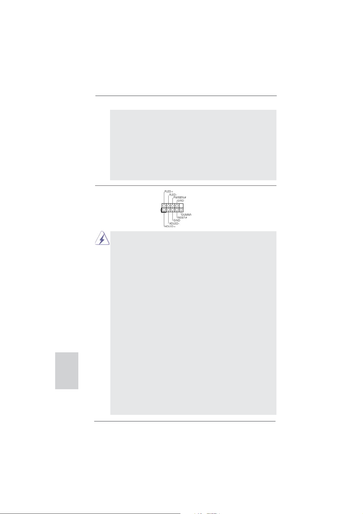
Deutsch
C. Schließen Sie Ground (GND) an Ground (GND) an.
D. MIC_RET und OUT_RET sind nur für den HD-Audioanschluss gedacht. Diese
Anschlüsse müssen nicht an die AC’97-Audioleiste angeschlossen werden.
E. So aktivieren Sie das Mikrofon an der Vorderseite.
Bei den Betriebssystemen Windows
Wählen Sie „Mixer“. Wählen Sie „Recorder“ (Rekorder). Klicken Sie dann auf
„FrontMic“ (Vorderes Mikrofon).
Bei den Betriebssystemen Windows
Wählen Sie im Realtek-Bedienfeld die „FrontMic“ (Vorderes Mikrofon) Registerkarte. Passen Sie die „Recording Volume“ (Aufnahmelautstärke) an.
®
XP / XP 64 Bit:
®
7 / 7 64 Bit / VistaTM / VistaTM 64 Bit:
System Panel-Header Dieser Header unterstützt
(9-pin PANEL1)
(siehe S.2 - No. 17)
Schließen Sie die Ein-/Austaste, die Reset-Taste und die
Systemstatusanzeige am Gehäuse an diesen Header an; befolgen Sie
dabei die nachstehenden Hinweise zur Pinbelegung. Beachten Sie die
positiven und negativen Pins, bevor Sie die Kabel anschließen.
PWRBTN (Ein-/Ausschalter):
RESET (Reset-Taste):
PLED (Systembetriebs-LED):
HDLED (Festplattenaktivitäts-LED):
mehrere Funktion der
Systemvorderseite.
Zum Anschließen des Ein-/Ausschalters an der Frontblende des Gehäu
ses. Sie können konfi gurieren, wie das System mit Hilfe des
Ein-/Ausschalters ausgeschaltet werden können soll.
Zum Anschließen der Reset-Taste an der Frontblende des Gehäuses.
Mit der Reset-Taste können Sie den Computer im Falle eines Absturzes
neu starten.
Zum Anschließen der Betriebsstatusanzeige an der Frontblende des
Gehäuses. Die LED leuchtet, wenn das System in Betrieb ist. Die LED
blinkt, wenn sich das System im Ruhezustand S1/S3 befi ndet. Die LED
schaltet sich aus, wenn sich das System in den Modi S4 befi ndet
oder ausgeschaltet ist (S5).
Zum Anschließen der Festplattenaktivitäts-LED an der Frontblende des
Gehäuses. Die LED leuchtet, wenn die Festplatte Daten liest oder
schreibt.
Das Design der Frontblende kann je nach Gehäuse variiere. Ein
Frontblendenmodul besteht hauptsächlich aus einer Ein-/Austaste, einer
Reset-Taste, einer Betriebs-LED, einer Festplattenaktivitäts-LED,
Lautsprechern, etc. Stellen Sie beim Anschließen des
46
ASRock Z77E-ITX Motherboard
Page 47
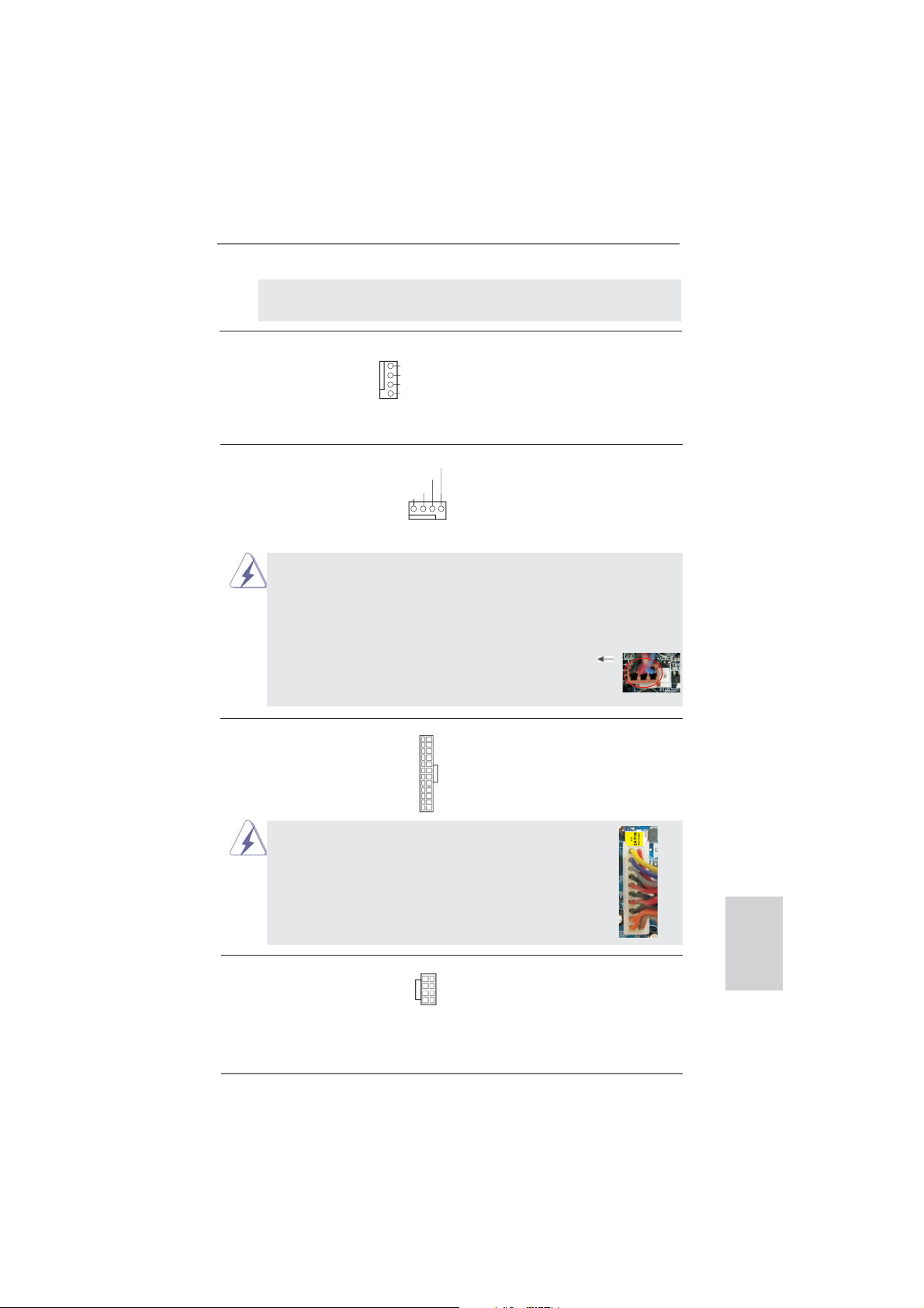
Frontblendenmoduls Ihres Gehäuses an diesem Header sicher, dass die
Kabel- und Pinbelegung korrekt übereinstimmen.
Gehäuse lüfteranschlüsse Verbinden Sie die Lüfterkabel
(4-pin CHA_FAN1)
(siehe S.2, No. 13)
den Schutzleiterstift
mit den Lüfteranschlüssen,
wobei der schwarze Draht an
GND
+12V
CHA_FAN_SPEED
FAN_SPEED_CONTROL
angeschlossenwird.
CPU-Lüfteranschluss Verbinden Sie das CPU -
(4-pin CPU_FAN1)
(siehe S.2 - No. 10)
Lüfterkabel mit diesem
Anschluss und passen Sie den
schwarzen Draht dem
Erdungsstift an.
FAN_SPEED_CONTROL
CPU_FAN_SPEED
+12V
GND
1 2 3 4
Obwohl dieses Motherboard einen vierpoligen CPU-Lüfteranschluss
(Quiet Fan) bietet, können auch CPU-Lüfter mit dreipoligem Anschluss
angeschlossen werden; auch ohne Geschwindigkeitsregulierung. Wenn
Sie einen dreipoligen CPU-Lüfter an den CPU-Lüferanschluss dieses
Motherboards anschließen möchten, verbinden Sie ihn bitte mit den
Pins 1 – 3.
Pins 1–3 anschließen
Lüfter mit dreipoligem Anschluss installieren
ATX-Netz-Header Verbinden Sie die ATX-
(24-pin ATXPWR1)
(siehe S.2 - No. 16)
Obwohl dieses Motherboard einen 24-pol. ATX-
Stromversorgung mit diesem
Header.
12 124
13
12
24
Stromanschluss bietet, kann es auch mit einem
modifi zierten traditionellen 20-pol. ATX-Netzteil
verwendet werden. Um ein 20-pol. ATX-Netzteil zu
verwenden, stecken Sie den Stecker mit Pin 1 und
Pin 13 ein.
Installation eines 20-pol. ATX-Netzteils
1
13
24
13
ATX 12V Anschluss Bitte schließen Sie an diesen
(8-pin ATX12V1)
(siehe S.2 - No. 22)
Anschluss die ATX 12V
Stromversorgung an.
5 1
8 4
ASRock Z77E-ITX Motherboard
Deutsch
47
Page 48

Obwohl diese Hauptplatine 8-Pin ATX 12V Stromanschluss zur Verfügung
stellt, kann sie noch arbeiten, wenn Sie einen traditionellen 4-Pin ATX 12V
Energieversorgung adoptieren. Um die 4-Pin ATX Energieversorgung zu
verwenden, stecken Sie bitte Ihre Energieversorgung zusammen mit dem
Pin 1 und Pin 5 ein.
5 1
Deutsch
Installation der 4-Pin ATX 12V Energieversorgung
8 4
2. BIOS-Information
Das Flash Memory dieses Motherboards speichert das Setup-Utility. Drücken Sie
<F2> oder <Del> während des POST (Power-On-Self-Test) um ins Setup zu gelangen, ansonsten werden die Testroutinen weiter abgearbeitet. Wenn Sie ins Setup
gelangen wollen, nachdem der POST durchgeführt wurde, müssen Sie das System
über die Tastenkombination <Ctrl> + <Alt> + <Delete> oder den Reset-Knopf auf
der Gehäusevorderseite, neu starten. Natürlich können Sie einen Neustart auch
durchführen, indem Sie das System kurz ab- und danach wieder anschalten.
Das Setup-Programm ist für eine bequeme Bedienung entwickelt worden. Es ist
ein menügesteuertes Programm, in dem Sie durch unterschiedliche Untermenüs
scrollen und die vorab festgelegten Optionen auswählen können. Für detaillierte
Informationen zum BIOS-Setup, siehe bitte das Benutzerhandbuch (PDF Datei) auf
der Support CD.
3. Software Support CD information
Dieses Motherboard unterstützt eine Reiche von Microsoft® Windows® Betriebssystemen: 7 / 7 64-Bit / Vista
beigefügte Support-CD enthält hilfreiche Software, Treiber und Hilfsprogramme, mit
denen Sie die Funktionen Ihres Motherboards verbessern können Legen Sie die
Support-CD zunächst in Ihr CD-ROM-Laufwerk ein. Der Willkommensbildschirm
mit den Installationsmenüs der CD wird automatisch aufgerufen, wenn Sie die
“Autorun”-Funktion Ihres Systems aktiviert haben.
Erscheint der Wilkommensbildschirm nicht, so “doppelklicken” Sie bitte auf das File
ASSETUP.EXE im BIN-Verzeichnis der Support-CD, um die Menüs aufzurufen.
Das Setup-Programm soll es Ihnen so leicht wie möglich machen. Es ist menügesteuert, d.h. Sie können in den verschiedenen Untermenüs Ihre Auswahl treffen und
die Programme werden dann automatisch installiert.
TM
/ Vista
TM
64-Bit / XP / XP 64-Bit. Die Ihrem Motherboard
48
ASRock Z77E-ITX Motherboard
Page 49

1. Introduction
Merci pour votre achat d’une carte mère ASRock Z77E-ITX, une carte mère très
fi able produite selon les critères de qualité rigoureux de ASRock. Elle offre des
performances excellentes et une conception robuste conformément à l’engagement
d’ASRock sur la qualité et la fi abilité au long terme.
Ce Guide d’installation rapide présente la carte mère et constitue un guide
d’installation pas à pas. Des informations plus détaillées concernant la carte
mère pourront être trouvées dans le manuel l’utilisateur qui se trouve sur le CD
d’assistance.
Les spécifi cations de la carte mère et le BIOS ayant pu être mis à jour, le
contenu de ce manuel est sujet à des changements sans notifi cation. Au
cas où n’importe qu’elle modifi cation intervenait sur ce manuel, la version
mise à jour serait disponible sur le site web ASRock sans nouvel avis.
Vous trouverez les listes de prise en charge des cartes VGA et CPU
également sur le site Web ASRock.
Site web ASRock, http://www.asrock.com
Si vous avez besoin de support technique en relation avec cette carte
mère, veuillez consulter notre site Web pour de plus amples informations
particulières au modèle que vous utilisez.
www.asrock.com/support/index.asp
1.1 Contenu du paquet
Carte mère ASRock Z77E-ITX
(Facteur de forme Mini-ITX: 6.7 pouces x 6.7 pouces, 17.0 cm x 17.0 cm)
Guide d’installation rapide ASRock Z77E-ITX
CD de soutien ASRock Z77E-ITX
Deux câbles de données de série ATA (SATA) (en option)
Un Antenne wi-fi 2,4 GHz ASRock (en option)
Un Convertisseur DVI vers D-Sub (en option)
Un I/O Panel Shield
ASRock vous rappelle...
Pour bénéfi cier des meilleures performances sous Windows® 7 / 7 64 bits
TM
/ Vista
/ VistaTM 64 bits, il est recommandé de paramétrer l'option BIOS
dans Confi guration de stockage en mode AHCI. Pour plus de détails sur
l'installation BIOS, référez-vous au "Mode d'emploi" sur votre CD de support.
ASRock Z77E-ITX Motherboard
Français
49
Page 50

Français
1.2 Spécifications
Format - Facteur de forme Mini-ITX:
6.7 pouces x 6.7 pouces, 17.0 cm x 17.0 cm
- Design de condensateur Premium Gold (condensateurs
polymère conducteur de qualité supérieure 100% fabriqués
au Japon)
CPU - Prend en charge les processeurs Intel
2ème et 3ème génération sur socket LGA1155
- Conception Digi Power
- 6 + 2 Power Phase conception
- Prend en charge la technologie Intel
- Prise en charge des unités centrales non verrouillées de
série K
- Prise en charge de la technologie Hyper-Threading
(voir ATTENTION 1)
- Prend en charge les technologies Intel
Connect avec processeur Intel
Chipsets - Intel® Z77
Mémoire - Compatible avec la Technologie de Mémoire à Canal
Double (voir ATTENTION 2)
- 2 x slots DIMM DDR3
- Supporter DDR3 2800+(OC)/2400(OC)/2133(OC)/1866(OC)
/1600/1333/1066 non-ECC, sans amortissement mémoire
- Capacité maxi de mémoire système: 16GB
(voir ATTENTION 3)
- Prend en charge le profi l de mémoire extrême Intel
1.3/1.2
Slot d’extension - 1 x slot PCI Express 3.0 x16 (PCIE1 : mode x16)
(voir ATTENTION 4)
* PCIE 3.0 n’est pris en charge qu’avec le processeur Intel
Ivy Bridge. Avec le processeur Intel® Sandy Bridge, seul
PCIE 2.0 est pris en charge.
- 1 x emplacement mini-PCI Express : pour module wi-fi
VGA sur carte * Intel® HD Graphics avec visuels intégrés (Built-in Visuals) et
les sorties VGA sont uniquement pris en charge par les
processeurs à GPU intégré.
- Supporte Intel
Sync Video 2.0, Intel
®
HD Graphics Built-in Visuals: Intel® Quick
®
InTruTM 3D, Intel® Clear Video HD
Technology, Intel® InsiderTM, Intel® HD Graphics 2500/4000
- Pixel Shader 5.0, DirectX 11 avec CPU Intel® Ivy Bridge,
®
CoreTM i7 / i5 / i3
®
Turbo Boost 2.0
®
®
Rapid Start et Smart
Ivy Bridge CPU
®
(XMP)
®
50
ASRock Z77E-ITX Motherboard
Page 51

Pixel Shader 4.1, DirectX 10.1 avec CPU Intel® Sandy
Bridge
- Mémoire partagée max 1760MB (voir ATTENTION 5)
- Multi options de sortie VGA: DVI, HDMI, DisplayPort et
D-Sub avec convertisseur DVI-vers-D-Sub
(voir ATTENTION 6)
- Prend en charge le HDMI 1.4a avec une résolution
maximale jusqu’à 1920x1200 @ 60Hz
- Prend en charge le DVI avec une résolution maximale
jusqu’à 1920x1200 @ 60Hz
- Prend en charge le DisplayPort avec une résolution
maximale jusqu’à 2560x1600 @ 60Hz
- Prend en charge le D-Sub avec une résolution maximale
jusqu’à 2048x1536 @ 75Hz
- Prend en charge Lip Sync, Deep Color (12bpc), xvYCC et
HBR (High Bit Rate Audio : Audio à haut débit binaire) avec
HDMI (Moniteur compatible HDMI requis)
(voir ATTENTION 7)
- Prise en charge de la fonction HDCP avec ports DVI, HDMI
et DisplayPort
- Supporter 1080p Blu-ray(BD)/ lecteur de HD-DVD avec
ports DVI, HDMI et DisplayPort
Audio - 7,1 CH HD Audio avec protection de contenu
(Realtek ALC898 Audio Codec)
- Prise en charge de l’audio Premium Blu-ray
- Prend en charge THX TruStudio
TM
LAN - PCIE x1 Gigabit LAN 10/100/1000 Mb/s
- Broadcom BCM57781
- Support du Wake-On-LAN
- Prend en charge la norme Energy Effi cient Ethernet
(Ethernet à effi cacité énergétique) 802.3az
- Supporte PXE
LAN sans fi l Module WiFi-802.11n
- 300Mbps IEEE 802.11n / 54Mbps IEEE 802.11g / 11Mbps
IEEE 802.11b
- Prend en charge le mode Station (mode Infrastructure et
mode Ad-hoc)
Panneau arrière I/O Panel
- 2 x ports d’antenne
- 1 x port clavier/souris PS/2
- 1 x port DVI-I
- 1 x port HDMI
ASRock Z77E-ITX Motherboard
Français
51
Page 52

Français
- 1 x DisplayPort
- 1 x Port de sortie optique SPDIF
- 2 x ports USB 2.0 par défaut
- 1 x Connecteur eSATA2
- 4 x ports USB 3.0 par défaut
- 1 x port LAN RJ-45 avec LED (ACT/LED CLIGNOTANTE et
LED VITESSE)
- 1 x interrupteur d’effacement du CMOS avec LED
- Prise HD Audio: Haut-parleur arrière / Central /Basses /
Entrée Ligne / Haut-parleur frontal / Microphone
(voir ATTENTION 8)
SATA 3 - 2 x connecteurs SATA3 6,0 Gb/s, prennent en charge les
fonctions RAID (RAID 0, RAID 1, RAID 5, RAID 10, Intel
Rapid Storage et Intel Smart Response), NCQ, AHCI et Hot
Plug
USB 3.0 - 2 x ports USB3.0 à l’arrière par Intel
®
Z77, prennent en
charge USB 1.0/2.0/3.0 jusqu’à 5 Gb/s
- 2 x ports USB3.0 à l’arrière par ASMedia ASM1042,
prennent en charge USB 1.0/2.0/3.0 jusqu’à 5 Gb/s
- 1 x barrette USB3.0 en façade (prend en charge 2 ports
USB 3.0) par Intel
®
Z77, prend en charge USB 1.0/2.0/3.0
jusqu’à 5 Gb/s
Connecteurs - 2 x connecteurs SATA2, prennent en charge un taux de
transfert de données pouvant aller jusqu’à 3.0Go/s,
supporte RAID (RAID 0, RAID 1, RAID 5, RAID 10, Intel
Rapid Storage et Intel Smart Response), NCQ, AHCI et
Hot Plug (Branchement à chaud)
- 1 x connecteur mSATA 3,0 Go/s (connecteur Solid-State
Drive), prise en charge RAID (RAID 0, RAID 1, RAID 5,
RAID 10, Intel Rapid Storage et Intel Smart Response
Technology), fonctions NCQ, AHCI et pleine dimension
module mini-PCI Express
- 2 x connecteurs SATA3, prennent en charge un taux de
transfert de données pouvant aller jusqu’à 6.0Go/s
- 1 x
Barrette pour module à infrarouges grand public
- Connecteur pour ventilateur de CPU/Châssis Ventilateur
- br. 24 connecteur d’alimentation ATX
- br. 8 connecteur d’alimentation 12V ATX
- Connecteur audio panneau avant
- 2 x En-tête USB 2.0 (prendre en charge 4 ports USB 2.0
supplémentaires)
- 1 x En-tête USB 3.0 (prendre en charge 2 ports USB 3.0
52
ASRock Z77E-ITX Motherboard
Page 53

supplémentaires)
BIOS - 64Mb AMI UEFI Legal BIOS avec support GUI
- Support du “Plug and Play”
- Compatible pour événements de réveil ACPI 1.1
- Gestion jumperless
- Support SMBIOS 2.3.1
- CPU Core, IGPU, DRAM, VCCSA Tension Multi-ajustement
CD d’assistance - Pilotes, utilitaires, logiciel anti-virus (version d’évaluation),
CyberLink MediaEspresso 6.5 Trial, Suite multimédia
ASRock MAGIX - OEM
Caractéristique - Utilitaire ASRock Extreme Tuning (AXTU)
unique (voir ATTENTION 9)
- ASRock l’Instant Boot
- ASRock Instant Flash (voir ATTENTION 10)
- Chargeur ASRock APP (voir ATTENTION 11)
- ASRock SmartView (voir ATTENTION 12)
- ASRock XFast USB (voir ATTENTION 13)
- ASRock XFast LAN (voir ATTENTION 14)
- ASRock XFast RAM (voir ATTENTION 15)
- ASRock Crashless BIOS (voir ATTENTION 16)
- ASRock OMG (Online Management Guard)
(voir ATTENTION 17)
- ASRock Internet Flash (voir ATTENTION 18)
- Lucid Virtu Universal MVP (voir ATTENTION 19)
* Lucid Virtu Universal MVP est uniquement pris en charge
par les processeurs à GPU intégré.
- L’accélérateur hybride:
- Contrôle direct de la fréquence CPU
(voir ATTENTION 20)
- ASRock U-COP (voir ATTENTION 21)
- Garde d’échec au démarrage (B.F.G.)
- DEL veilleuse
Surveillance - Détection de la température de l’UC
système - Mesure de température de la carte mère
- Tachéomètre ventilateur processeur ventilateur
- Tachéomètre ventilateur châssis ventilateur
- Ventilateur silencieux pour unité centrale/châssis (permet le
réglage automatique de la vitesse du ventilateur pour
châssis, selon la température de l’unité centrale)
- Commande de ventilateur CPU/Châssis à plusieurs
vitesses
- Monitoring de la tension: +12V, +5V, +3.3V, Vcore
ASRock Z77E-ITX Motherboard
Français
53
Page 54

Français
OS - Microsoft® Windows® 7 / 7 64-bit / VistaTM / Vista
TM
64-bit
/ XP / XP 64-bit (voir ATTENTION 22)
Certifi cations - FCC, CE, WHQL
- Prêt pour ErP/EuP (alimentation Prêt pour ErP/EuP requise)
(voir ATTENTION 23)
* Pour de plus amples informations sur les produits, s’il vous plaît visitez notre site web:
http://www.asrock.com
ATTENTION
Il est important que vous réalisiez qu’il y a un certain risque à effectuer
l’overclocking, y compris ajuster les réglages du BIOS, appliquer la technologie
Untied Overclocking, ou utiliser des outils de tiers pour l’overclocking. L’overclocking
peut affecter la stabilité de votre système, ou même causer des dommages aux
composants et dispositifs de votre système. Si vous le faites, c’est à vos frais et
vos propres risques. Nous ne sommes pas responsables des dommages possibles
causés par l’overclocking.
ATTENTION!
1. En ce qui concerne le paramétrage “Hyper-Threading Technology”,
veuillez consulter la page 47 du manuel de l’utilisateur sur le CD tech-
nique.
2. Cette carte mère supporte la Technologie de Mémoire à Canal Double.
Avant d’intégrer la Technologie de Mémoire à Canal Double, assurezvous de bien lire le guide d’installation des modules mémoire en page 19
pour réaliser une installation correcte.
3. Du fait des limites du système d’exploitation, la taille mémoire réelle
réservée au système pourra être inférieure à 4 Go sous Windows
VistaTM / XP. Avec Windows® OS avec CPU 64 bits, il n’y a pas ce genre
de limitation. Vous pouvez utiliser ASRock XFast RAM pour accéder à la
mémoire que Windows® ne peut pas utiliser.
4. PCIE1 prend en charge une vitesse pouvant atteindre Gen 3. Pour
pouvoir utiliser PCI Express en vitesse Gen 3, vous devez installer le
processeur Ivy Bridge. Si vous installez le processeur Sandy Bridge, PCI
Express ne fonctionnera qu’en vitesse PCI Express Gen 2.
5. La dimension maximum du memoire partage est defi nie par le vendeur
de jeu de puces et est sujet de changer. Veuillez verifi er la Intel
pour les informations recentes SVP.
6. Vous pouvez choisir de n’utiliser que deux moniteurs sur trois. Les moniteurs DVI, HDMI et DisplayPort ne peuvent pas être activés en même
temps. En outre, avec l’adaptateur DVI-HDMI, le port DVI peut prendre
en charge les mêmes fonctions que le port HDMI.
7. xvYCC et Deep Color ne sont pris en charge que sous Windows
bit / 7. Le mode Deep Color ne sera activé que si le moniteur prend en
charge 12bpc en EDID. HBR est pris en charge sous Windows
7 / VistaTM 64-bit / VistaTM.
®
®
website
®
7 64-
®
7 64-bit /
7 /
54
ASRock Z77E-ITX Motherboard
Page 55

8. Pour l’entrée microphone, cette carte mère supporte les deux modes
stéréo et mono. Pour la sortie audio, cette carte mère supporte les
modes 2-canaux, 4-canaux, 6-canaux et 8-canaux. Veuillez vous référer
au tableau en page 4 pour effectuer la bonne connexion.
9. ASRock Extreme Tuning Utility (AXTU) est un utilitaire tout-en-un qui
permet de régler précisément différentes fonctions du système, via une
interface facile à utiliser, incluant Moniteur de périphériques, Contrôle du
ventilateur, Overclocking, OC DNA et IES. Dans Moniteur de
périphériques, il affi che les valeurs principales de votre système.
Dans Contrôle du ventilateur, il affi che la vitesse du ventilateur et la
température, que vous pouvez ajuster. Dans Overclocking, vous pouvez
overclocker la fréquence du CPU pour améliorer les performances du
système. Dans OC DNA, vous pouvez enregistrer vos réglages OC dans
un profi l et les partager avec vos amis. Vos amis pourront alors installer
le profi l OC sur leur système pour utiliser les mêmes réglages OC.
Dans IES (Intelligent Energy Saver – Fonction intelligente d’économie
d’énergie), le contrôleur de la tension peut réduire le nombre de phases
de sortie pour améliorer le fonctionnement lorsque les cores du CPU ne
sont pas utilisées, sans diminuer les performances de l’ordinateur.
Veuillez visiter notre site Web pour plus d’informations sur l’utilisation des
fonctions de l’utilitaire ASRock Extreme Tuning Utility (AXTU).
Site Web de ASRock : http://www.asrock.com
10. O ASRock Instant Flash é um utilitário de fl ash do BIOS incorporado
na memória Flash ROM. Esta prática ferramenta de actualização do
BIOS permite-lhe actualizar o BIOS do sistema sem necessitar de entrar
nos sistemas operativos, como o MS-DOS ou o Windows
utilitário, poderá premir a tecla <F6> durante o teste de arranque POST
ou premir a tecla <F2> para exibir o menu de confi guração do BIOS para
aceder ao ASRock Instant Flash. Execute esta ferramenta para guardar
o novo fi cheiro de BIOS numa unidade fl ash USB, numa disquete ou
num disco rígido, em seguida, poderá actualizar o BIOS com apenas
alguns cliques sem ter de utilizar outra disquete ou outro complicado
utilitário de fl ash. Note que a unidade fl ash USB ou a unidade de disco
rígido devem utilizar o sistema de fi cheiros FAT32/16/12.
11. Si vous désirez un moyen plus rapide et moins contraignant de recharger
vos appareils Apple tels que iPhone/iPad/iPod Touch, ASRock a préparé
pour vous la solution idéale - le chargeur ASRock APP. Il suffi t d’installer
le pilote du chargeur APP, et vous pourrez recharger rapidement votre
iPhone à partir de votre ordinateur, jusqu’à 40% plus vite qu’avant. Le
chargeur ASRock APP vous permet de charger rapidement et simultanément plusieurs appareils Apple, et le chargement continu est même
pris en charge lorsque le PC passe en mode Veille (S1), Suspension à
la RAM (S3), hibernation (S4) ou hors tension (S5). Lorsque le pilote du
chargeur APP est installé, vous découvrez un mode de mise en charge
tout à fait inédit.
Site web ASRock : http://www.asrock.com/Feature/AppCharger/index.asp
®
. Com este
Français
ASRock Z77E-ITX Motherboard
55
Page 56

Français
12. SmartView, une nouvelle fonction du navigateur Internet, est une page
de démarrage intelligente de IE, comportant à la fois vos sites Internet
les plus visités, votre historique, vos amis Facebook et l’actualité en
temps réel, le tout sur une vue optimisée pour une expérience de l’Internet
encore plus personnelle. Les cartes mères ASRock sont équipées en
exclusivité de l’utilitaire SmartView, ce qui vous permet de garder le
contact avec vos amis itinérants. Pour utiliser la fonction SmartView,
veuillez vous assurez que votre version de système d’exploitation est
®
Windows
navigateur IE8. Site Internet ASRock : http://www.asrock.com/Feature/
SmartView/index.asp
13. ASRock XFast USB permet d’améliorer les performances de votre péri-
phérique de stockage USB. Les performances réelles dépendent des
propriétés du périphérique.
14. ASRock XFast LAN fournit un accès Internet plus rapide, avec les avan-
tages suivants. Priorisation d’application LAN : Vous pouvez confi gurer
votre priorité d’application idéalement et/ou ajouter des nouveaux programmes. Latence plus basse dans les jeux : Après avoir réglé la priorité
de jeux en ligne plus haute, cela peut réduire la latence dans les jeux
Forme du trafi c : Vous pouvez regarder des vidéos HD YouTube et té-
lécharger simultanément des fi chiers. Analyse en temps réel de vos don-
nées : Avec la fenêtre d’état, vous pouvez facilement reconnaître les fl ux
de données que vous êtes en train de transférer.
15. ASRock XFast RAM est une nouvelle fonction intégrée à l’utilitaire
ASRock Extreme Tuning Utility (AXTU). Il utilise à sa pleine capacité
l’espace mémoire que les processeurs du système d’exploitation Windows OS 32-bit ne peuvent pas utiliser. ASRock XFast RAM diminue
le temps de chargement des sites Internet précédemment visités, rendant la navigation sur le web plus rapide que jamais. Il rend également
l’utilisation de Adobe Photoshop 5 fois plus rapide. Un autre avantage
indéniable de ASRock XFast RAM est qu’il réduit la fréquence d’accès à
vos SSD ou HDD afi n d’accroitre leur durée de vie utile.
16. ASRock Crashless BIOS permet aux utilisateurs de mettre à jour leur
BIOS sans qu’ils aient à craindre un plantage ou une défaillance. Si
l’alimentation venait à être coupée durant la mise à jour du BIOS, ASRock Crashless BIOS terminera automatiquement la mise à jour du BIOS
une fois le courant rétabli. Veuillez noter que les fi chiers BIOS doivent
être placés dans le répertoire racine de votre disque USB. Seuls les
ports USB2.0 sont compatibles avec cette fonction.
17. Grâce à OMG, les administrateurs ont la possibilité de créer un couvre-
feu Internet ou de limiter l’accès à Internet à des périodes spécifi ques.
Choisissez entre les options [Quotidien], [Jour de la semaine] ou [Jours
de la semaine et week-ends], puis programmez l’heure de début et de
fi n de l’accès Internet accordé à d’autres utilisateurs. Afi n d’éviter tout
contournement du système OMG par les utilisateurs, des comptes invité
sans autorisation d’accès à la modifi cation de l’heure système sont req-
uis.
7 / 7 64 bits / VistaTM / VistaTM 64 bits, et que vous utilisez le
56
ASRock Z77E-ITX Motherboard
Page 57

18. La fonction Internet Flash recherche les mises à jour disponibles pour le
microprogramme UEFI sur nos serveurs. En d’autres termes, le système
est capable de détecter automatiquement la mise à jour UEFI la plus
récente sur nos serveurs et la transmet sans avoir à accéder au système
d’exploitation Windows. Veuillez noter que le service DHCP doit être activé sur votre ordinateur pour pouvoir utiliser cette fonction.
19. VIRTU Universal MVP intègre toutes les fonctionnalités de base de la
technologie Virtu Universal, qui virtualise GPU intégrée et GPU discrète
pour des fonctionnalités optimales. Il est également doté de la fonction
Virtual Vsync
TM
pour une qualité visuelle sans compromis. Ajoutez à cela
les avantages de la technologie HyperFormance, et VIRTU Universal
MVP vous permettra d’obtenir des performances de jeu inégalées en
réduisant intelligemment les tâches redondantes du rendu lors du fl ux
entre le CPU, le GPU de la carte graphique et l’écran.
20. Même si cette carte mère offre un contrôle sans souci, il n’est pas recommandé d’y appliquer un over clocking. Des fréquences de bus CPU
autres que celles recommandées risquent de rendre le système instable
ou d’endommager le CPU et la carte mère.
21. Lorsqu’une surchauffe du CPU est détectée, le système s’arrête automatiquement. Avant de redémarrer le système, veuillez vérifi er que le ven-
tilateur d’UC sur la carte mère fonctionne correctement et débranchez le
cordon d’alimentation, puis rebranchez-le. Pour améliorer la dissipation
de la chaleur, n’oubliez pas de mettre de la pâte thermique entre le CPU
le dissipateur lors de l’installation du PC.
22. ASRock XFast RAM n’est pas pris en charge par Microsoft
XP / XP 64-bit. Les technologie Intel® Smart Connect et ports Intel® USB
3.0 n’est pas pris en charge par Microsoft
®
Windows® VistaTM / VistaTM 64-
®
Windows®
bit / XP / XP 64-bit.
23. EuP, qui signifi e Energy Using Product (Produit Utilisant de l’Energie),
est une disposition établie par l’Union Européenne pour défi nir la con-
sommation de courant pour le système entier. Conformément à la norme
EuP, le courant CA total du système entier doit être inférieur à 1 W en
mode d’arrêt. Pour être conforme à la norme EuP, une carte mère EuP
et une alimentation EuP sont requises. Selon les suggestions d’Intel’,
l’alimentation électrique EuP doit correspondre à la norme, qui est que
l’effi cacité électrique de 5v en mode de veille doit être supérieure à 50%
pour 100 mA de consommation de courant. Pour choisir une alimentation
électrique conforme à la norme EuP, nous vous recommandons de consulter votre fournisseur de courant pour plus de détails.
ASRock Z77E-ITX Motherboard
Français
57
Page 58
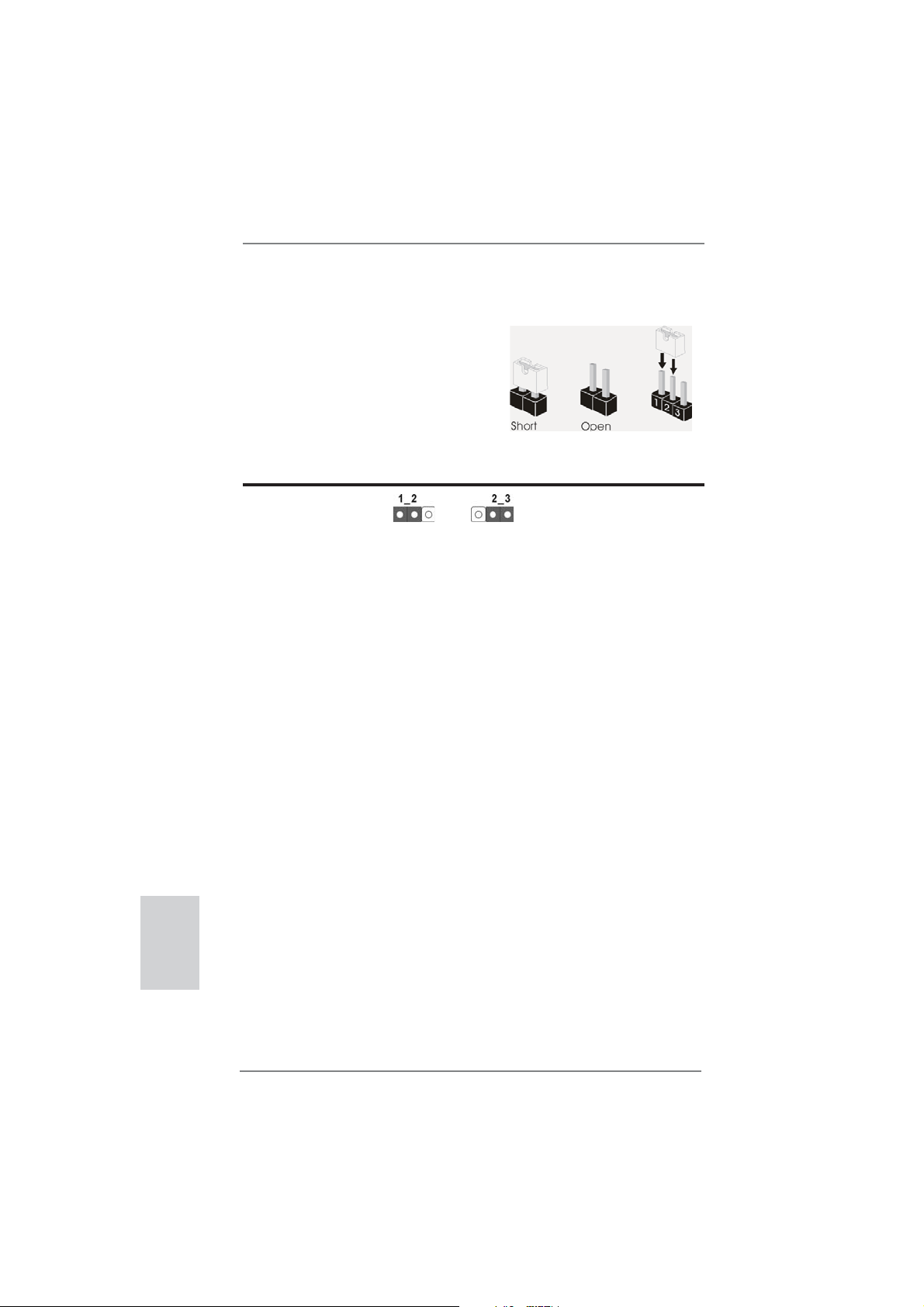
1.3 Réglage des cavaliers
L’illustration explique le réglage des cavaliers. Quand un capuchon est placé sur les
broches, le cavalier est « FERME ». Si aucun capuchon ne relie les broches,le cavalier est « OUVERT ». L’illustration montre un
cavalier à 3 broches dont les broches 1 et 2
sont « FERMEES » quand le capuchon est
placé sur ces 2 broches.
Le cavalier Description
Effacer la CMOS
(CLRCMOS1)
(voir p.2 fi g. 11)
Remarque :
Paramètres
par défaut
CLRCMOS1 vous permet d’effacer les données du CMOS. Pour effacer
et réinitialiser les paramètres du système à la confi guration originale,
veuillez éteindre l’ordinateur et débrancher le cordon d’alimentation de
la prise de courant. Après 15 secondes, utilisez un couvercle de jumper
pour court-circuiter les broches pin2 et pin3 de CLRCMOS1 pendant
secondes. Veuillez cependant ne pas effacer le CMOS immédiatement
a
près avoir mis à jour le BIOS. Si vous avez besoin d’effacer le CMOS
après avoir mis à jour le BIOS, vous devez allumer en premier le
système, puis l’éteindre avant de continuer avec l’opération d’effacement
du CMOS. Veuillez noter que le mot de passe, la date, l’heure, le profi l
par défaut de l’utilisateur, 1394 GUID et l’adresse MAC seront effacés
seulement si la batterie du CMOS est enlevée.
Effacer la
CMOS
5
Français
58
ASRock Z77E-ITX Motherboard
Page 59

1.4 En-têtes et Connecteurs sur Carte
Les en-têtes et connecteurs sur carte NE SONT PAS des cavaliers.
NE PAS placer les capuchons de cavalier sur ces en-têtes et connecteurs. Le fait de placer les capuchons de cavalier sur les en-têtes
et connecteurs causera à la carte mère des dommages irréversibles!
Connecteurs Série ATA2 Ces deux connecteurs Série
(SATA_2: voir p.2 No. 4)
(SATA_3: voir p.2 No. 1)
ATA2 (SATA2) prennent en
charge les câbles SATA pour
les périphériques de stockage
internes. L’interface SATA2
SATA_2
SATA_3
actuelle permet des taux
transferts de données pouvant
aller jusqu’à 3,0 Gb/s.
Connecteurs Série ATA3 Ces deux connecteurs Série
(SATA3_0: voir p.2 No. 3)
(SATA3_1: voir p.2 No. 2)
ATA3 (SATA3) prennent en
charge les câbles SATA pour
les périphériques de stockage
internes. L’interface SATA3
SATA3_0
SATA3_1
actuelle permet des taux
transferts de données pouvant
aller jusqu’à 6,0 Gb/s.
Connecteur mSATA Ce connecteur mSATA peut
(voir p.3 No. 23)
servir à connecter un Solid State Drive (SSD) pour un
dispositif de stockage externe.
L’interface mSATA actuelle
permet des débits de transfert
de données jusqu’à 3,0 Gb/s.
Câble de données Toute cote du cable de data
Série ATA (SATA) SATA peut etre connecte au
(en option)
disque dur SATA / SATA2 /
SATA3 ou au connecteur SATA2
/ SATA3 sur la carte
Français
mere.
59
ASRock Z77E-ITX Motherboard
Page 60
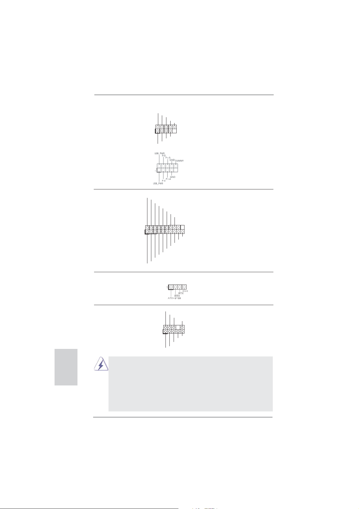
En-tête USB 2.0 A côté des deux ports USB 2.0
(USB2_3 br. 9)
(voir p.2 No. 5)
par défaut sur le panneau E/S,
il y a deux embases USB 2.0
sur cette carte mère. Chaque
embase USB 2.0 peut prendre
en charge 2 ports USB 2.0.
1
USB_PWR
P-3
P-2
USB_PWR
P+3
P+2
GND
GND
DUMMY
(USB64_5 br. 9)
(voir p.2 No. 6)
Français
En-tête USB 3.0 En plus des quatre ports USB
(USB3_3_4 br. 19)
(voir p.2 No. 8)
3.0 par défaut sur le panneau
E/S, il y a une barrette USB 3.0
sur la carte mère. Cette barrette
IntA_P0_D+
IntA_P0_D-
GND
IntA_P0_SSTX+
IntA_P0_SSTX-
GND
IntA_P0_SSRX+
IntA_P0_SSRX-
Vbus
USB 3.0 peut prendre en
charge deux ports USB 3.0.
1
GND
IntA_P1_D-
IntA_P1_D+
IntA_P1_SSRX+
GND
IntA_P1_SSTX-
IntA_P1_SSTX+
Vbus
IntA_P1_SSRX-
Barrette pour module à infrarouges grand public Cette barrette peut être utilisée
(CIR1 br.4)
(voir p.2 No. 7)
Connecteur audio panneau C’est une interface pour un
(HD_AUDIO1 br. 9)
(voir p.2 No. 19)
contrôle commodes de
périphériques audio.
1. L’audio à haute défi nition (HDA) prend en charge la détection de fi che, mais le fi l
de panneau sur le châssis doit prendre en charge le HDA pour fonctionner
correctement. Veuillez suivre les instructions dans notre manuel et le manuel de
châssis afi n installer votre système.
2. Si vous utilisez le panneau audio AC’97, installez-le sur l’adaptateur audio
du panneau avant conformément à la procédure ci-dessous:
A. Connectez Mic_IN (MIC) à MIC2_L.
B. Connectez Audio_R (RIN) à OUT2_R et Audio_L (LIN) à OUT2_L.
pour connecter des récepteur.
GND
GND
PRESENCE#
PRESENCE#
MIC_RET
1
1
MIC2_R
MIC2_R
MIC2_L
MIC2_L
MIC_RET
J_SENSE
J_SENSE
OUT2_R
OUT2_R
OUT_RET
OUT_RET
OUT2_L
OUT2_L
câble avant audio en façade qui
permet le branchement et le
60
ASRock Z77E-ITX Motherboard
Page 61
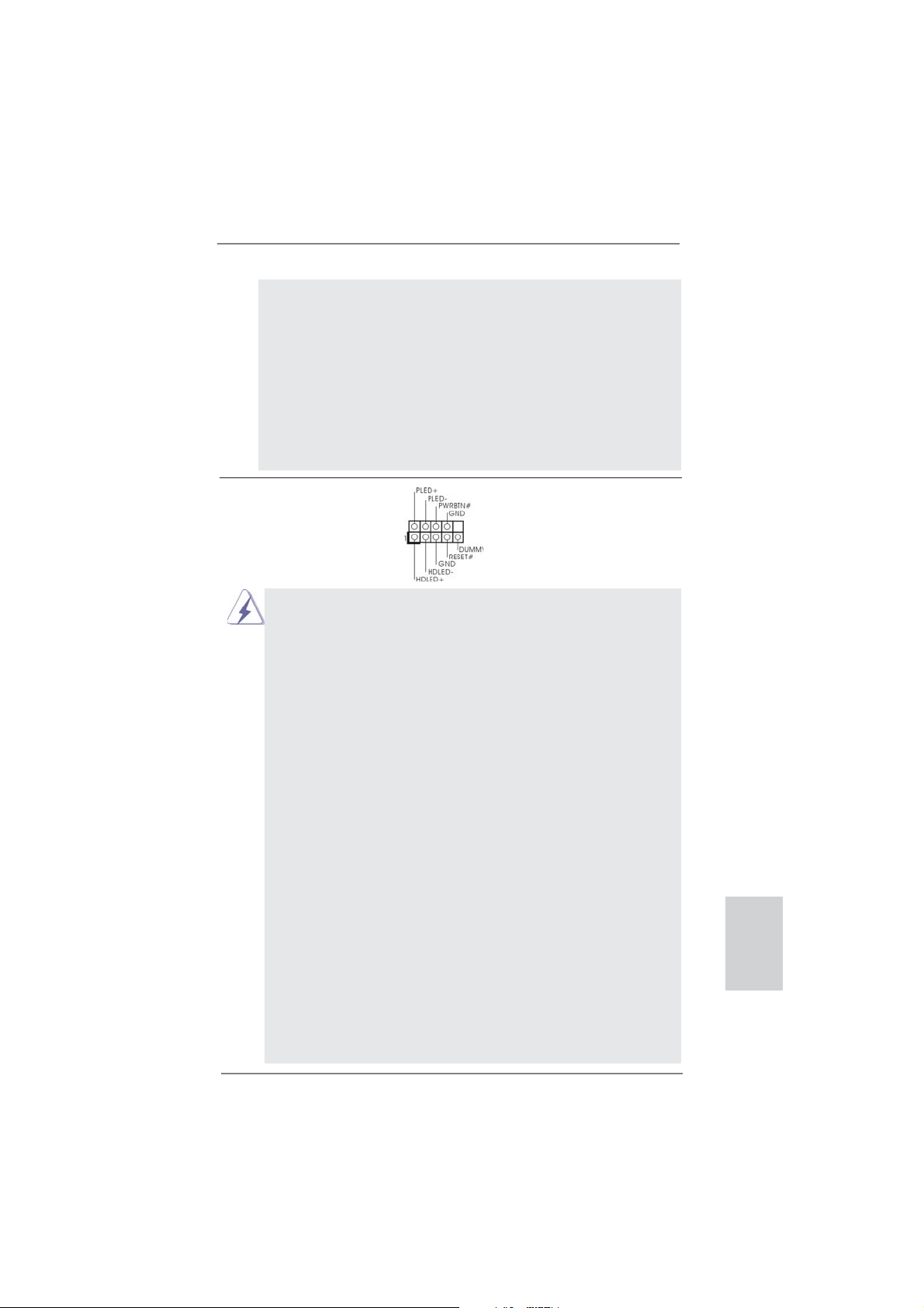
C. Connectez Ground (GND) à Ground (GND).
D. MIC_RET et OUT_RET sont réservés au panneau audio HD. Vous
n’avez pas besoin de les connecter pour le panneau audio AC’97.
E. Pour activer le micro avant.
Pour les systèmes d’exploitation Windows
Sélectionnez “Mixer”. Sélectionnez “Recorder” (Enregistreur). Puis
cliquez sur “FrontMic” (Micro avant).
Pour les systèmes d’exploitation Windows® 7 / 7 64 bits / VistaTM /
Vista
Allez sur l’onglet “FrontMic” (Micro avant) sur le Panneau de contrôle
Realtek. Ajustez “Recording Volume” (Volume d’enregistrement).
TM
64 bits :
®
XP / XP 64 bits :
En-tête du panneau système Cet en-tête permet d’utiliser
(PANEL1 br. 9)
(voir p.2 No. 17)
Connectez l’interrupteur d’alimentation, l’interrupteur de réinitialisation et
l’indicateur d’état du système du châssis sur cette barrette en respectant
l’affectation des broches décrite ci-dessous. Faites attention aux broches
positives et négatives avant de connecter les câbles.
PWRBTN (Interrupteur d’alimentation):
RESET (Interrupteur de réinitialisation):
PLED (DEL alimentation système):
HDLED (DEL activité du disque dur):
Le design du panneau avant peut varier en fonction du châssis. Un
module de panneau avant consiste principalement en : interrupteur
d’alimentation, interrupteur de réinitialisation, voyant DEL d’alimentation,
voyant DEL d’activité du disque dur, haut-parleur, etc. Lorsque vous
connectez le panneau avant de votre châssis sur cette barrette, vérifi ez
bien à faire correspondre les fi ls et les broches.
plusieurs fonctions du panneau
système frontal.
Connectez ici le connecteur d’alimentation sur le panneau avant du
châssis. Vous pouvez confi gurer la façon de mettre votre système hors
tension avec l’interrupteur d’alimentation.
Connectez ici le connecteur de réinitialisation sur le panneau avant du
châssis. Appuyez sur l’interrupteur de réinitialisation pour redémarrer
l’ordinateur s’il se bloque ou s’il n’arrive pas à redémarrer normalement.
Connectez ici l’indicateur d’état de l’alimentation sur le panneau avant du
châssis. Ce voyant DEL est allumé lorsque le système est en marche.
Le voyant DEL clignote lorsque le système est en mode veille S1/S3. Le
voyant DEL est éteint lorsque le système est en mode veille S4 ou
lorsqu’il est éteint (S5).
Connectez ici le voyant DEL d’activité du disque dur sur le panneau
avant du châssis. Ce voyant DEL est allumé lorsque le disque dur est en
train de lire ou d’écrire des données.
ASRock Z77E-ITX Motherboard
Français
61
Page 62

Connecteur pour châssis ventilateur Branchez les câbles du
(CHA_FAN1 br. 4)
(voir p.2 No. 13)
correspondre le fi l noir à la
ventilateur aux connecteurs
pour ventilateur et faites
GND
+12V
CHA_FAN_SPEED
FAN_SPEED_CONTROL
broche de terre.
Connecteur du ventilateur Veuillez connecter le câble de
de l’UC ventilateur d’UC sur ce
(CPU_FAN1 br. 4)
(voir p.2 No. 10)
connecteur et brancher le fi l
noir sur la broche de terre.
FAN_SPEED_CONTROL
CPU_FAN_SPEED
+12V
GND
1 2 3 4
Bien que cette carte mère offre un support de (Ventilateur silencieux
ventilateur de CPU à 4 broches , le ventilateur de CPU à 3 broches peut
bien fonctionner même sans la fonction de commande de vitesse du
ventilateur. Si vous prévoyez de connecter le ventilateur de CPU à 3
broches au connecteur du ventilateur de CPU sur cette carte mère,
veuillez le connecter aux broches 1-3.
Installation de ventilateur à 3 broches
Broches 1-3 connectées
En-tête d’alimentation ATX Veuillez connecter l’unité
(ATXPWR1 br. 24)
(voir p.2 No. 16)
Bien que cette carte mère fournisse un connecteur de
d’alimentation ATX sur cet en-
tête.
12 124
13
12
24
courant ATX 24 broches, elle peut encore fonctionner
si vous adopter une alimentation traditionnelle ATX 20
broches. Pour utiliser une alimentation ATX 20 broches,
branchez à l’alimentation électrique ainsi qu’aux
broches 1 et 13.
20-Installation de l’alimentation électrique ATX
1
13
Français
Connecteur ATX 12V Veuillez connecter une unité
(ATX12V1 br.8)
(voir p.2 No. 22)
d’alimentation électrique ATX
12V sur ce connecteur.
5 1
8 4
Bien que cette carte mère possède 8 broches connecteur d’alimentation
ATX 12V, il peut toujours travailler si vous adoptez une approche
traditionnelle à 4 broches ATX 12V alimentation.
Pour utiliser l’alimentation des 4 broches ATX,
branchez votre alimentation avec la broche 1 et
la broche 5.
4-Installation d’alimentation à 4 broches ATX 12V
62
ASRock Z77E-ITX Motherboard
5 1
8 4
Page 63

2. Informations sur le BIOS
La puce Flash Memory sur la carte mère stocke le Setup du BIOS. Lorsque vous
démarrez l’ordinateur, veuillez presser <F2> ou <Del> pendant le POST (Power-OnSelf-Test) pour entrer dans le BIOS; sinon, le POST continue ses tests de routine. Si
vous désirez entrer dans le BIOS après le POST, veuillez redémarrer le système en
pressant <Ctl> + <Alt> + <Suppr>, ou en pressant le bouton de reset sur le boîtier
du système. Vous pouvez également redémarrer en éteignant le système et en le
rallumant. L’utilitaire d’installation du BIOS est conçu pour être convivial. C’est un
programme piloté par menu, qui vous permet de faire défi ler par ses divers sous-
menus et de choisir parmi les choix prédéterminés. Pour des informations détaillées
sur le BIOS, veuillez consulter le Guide de l’utilisateur (fi chier PDF) dans le CD
technique.
3. Informations sur le CD de support
Cette carte mère supporte divers systèmes d’exploitation Microsoft® Windows®: 7
/ 7 64 bits / Vista
cette carte mère contient les pilotes et les utilitaires nécessaires pour améliorer les
fonctions de la carte mère. Pour utiliser le CD technique, insérez-le dans le lecteur
de CD-ROM. Le Menu principal s’affi che automatiquement si “AUTORUN” est activé
dans votre ordinateur. Si le Menu principal n’apparaît pas automatiquement, localisez dans le CD technique le fi chier “ASSETUP.EXE” dans le dossier BIN et double-
cliquez dessus pour affi cher les menus.
TM
/ Vista
TM
64 bits / XP / XP 64 bits. Le CD technique livré avec
ASRock Z77E-ITX Motherboard
Français
63
Page 64

1. Introduzione
Grazie per aver scelto una scheda madre ASRock Z77E-ITX, una scheda madre
affi dabile prodotta secondo i severi criteri di qualità ASRock. Le prestazioni
eccellenti e il design robusto si conformano all’impegno di ASRock nella ricerca
della qualità e della resistenza.
Questa Guida Rapida all’Installazione contiene l’introduzione alla motherboard e la
guida passo-passo all’installazione. Informazioni più dettagliate sulla motherboard si
possono trovare nel manuale per l’utente presente nel CD di supporto.
Le specifi che della scheda madre e il software del BIOS possono essere
aggiornati, pertanto il contenuto di questo manuale può subire
variazioni senza preavviso. Nel caso in cui questo manuale sia
modifi cato, la versione aggiornata sarà disponibile sul sito di ASRock
senza altro avviso. Sul sito ASRock si possono anche trovare le più
recenti schede VGA e gli elenchi di CPU supportate.
ASRock website http://www.asrock.com
Se si necessita dell’assistenza tecnica per questa scheda madre, visitare
il nostro sito per informazioni specifi che sul modello che si sta usando.
www.asrock.com/support/index.asp
1.1 Contenuto della confezione
Scheda madre ASRock Z77E-ITX
(Mini-ITX Form Factor: 6.7-in x 6.7-in, 17.0 cm x 17.0 cm)
Guida di installazione rapida ASRock Z77E-ITX
CD di supporto ASRock Z77E-ITX
Due cavi dati Serial ATA (SATA) (opzionali)
Un Antenna WiFi 2,4GHz ASRock (opzionali)
Un Convertitore DVI a D-Sub (opzionali)
Un I/O Shield
Italiano
64
ASRock vi ricorda...
Per ottenere migliori prestazioni in Windows® 7 / 7 64-bit / Vista
64-bit, si consiglia di impostare l'opzione BIOS in Storage Confi guration
(Confi gurazione di archiviazione) sulla modalità AHCI. Per l'impostazione
BIOS, fare riferimento a “User Manual” (Manuale dell'utente) nel CD di
supporto per dettagli.
TM
/ VistaTM
ASRock Z77E-ITX Motherboard
Page 65
1.2 Specifiche
Piattaforma - Mini-ITX Form Factor: 6.7-in x 6.7-in, 17.0 cm x 17.0 cm
- Design Premium Gold Capacitor (condensatori a polimeri
conduttivi di altissima qualità 100% made in Japan)
Processore - Supporta Intel
pacchetto LGA1155
- Design Digi Power
- Struttura di fase con alimentazione 6 + 2
- Supporto della tecnologia Intel
- Supporta CPU unlocked serie K
- Supporto tecnologia Hyper Threading (vedi ATTENZIONE 1)
- Supporta tecnologia Intel® Rapid Start Technology e Smart
Connect Technology con CPU Intel® Ivy Bridge
Chipset - Intel
®
Z77
Memoria - Supporto tecnologia Dual Channel Memory
(vedi ATTENZIONE 2)
- 2 x slots DDR3 DIMM
- Supporto DDR3 2800+(OC)/2400(OC)/2133(OC)/1866(OC)/
1600/1333/1066 non-ECC, momoria senza buffer
- Capacità massima della memoria di sistema: 16GB
(vedi ATTENZIONE 3)
- Supporto di Intel
Slot di - 1 x Alloggio PCI Express 3.0 x16 (PCIE1 : modalità x16)
espansione (vedi ATTENZIONE 4)
* PCIE 3.0 è supportato soltanto con la CPU Intel
Con la CPU Intel® Sandy Bridge, supporta solamente PCIE
2.0.
- 1 x alloggio mini-PCI Express: per modulo WiFi
VGA su scheda * Le uscite Intel® HD Graphics Built-in Visuals e VGA possono
essere supportate solo con processori dotati di GPU
integrata.
- Supporta Intel
Video 2.0, Intel® InTruTM 3D, Intel® Clear Video HD Technology,
Intel
®
InsiderTM, Intel® HD Graphics 2500/4000
- Pixel Shader 5.0, DirectX 11 con CPU Intel® Ivy Bridge, Pixel
Shader 4.1, DirectX 10.1 con CPU Intel® Sandy Bridge
- Memoria massima condivisa 1760MB (vedi ATTENZIONE 5)
- Multi opzioni d’output VGA: DVI, HDMI, DisplayPort e D-Sub
con convertitore DVI-to-D-Sub (vedi ATTENZIONE 6)
- Supporta HDMI 1.4a con risoluzione massima fi no a
1920x1200 @ 60Hz
ASRock Z77E-ITX Motherboard
®
CoreTM i7 / i5 / i3 di 3a e 2a generazione in un
®
Turbo Boost 2.0
®
XMP (Extreme Memory Profi le)1.3/1.2
®
Ivy Bridge.
®
HD Graphics Built-in Visuals: Intel® Quick Sync
Italiano
65
Page 66

Italiano
- Supporta DVI con risoluzione massima fi no a 1920x1200 @
60Hz
- Supporta DisplayPort con risoluzione massima fi no a
2560x1600 @ 60Hz
- Supporta D-Sub con risoluzione massima fi no a 2048x1536 @
75Hz
- Supporto delle funzioni Auto Lip Sync, Deep Color (12bpc),
xvYCC e HBR (High Bit Rate Audio) con HDMI (è necessario
un monitor compatibile HDMI) (vedi ATTENZIONE 7)
- Supporto della funzione HDCP con le porte DVI, HDMI e
DisplayPort
- Supporto 1080p Blu-ray (BD) / HD-DVD riproduzione con le
porte DVI, HDMI e DisplayPort
Audio - 7.1 CH HD Audio con protezioni contenuti
(Realtek ALC898 Audio Codec)
- Supporto audio Blu-ray Premium
- Supporto THX TruStudio
TM
LAN - PCIE x1 Gigabit LAN 10/100/1000 Mb/s
- Broadcom BCM57781
- Supporta Wake-On-LAN
- Supporto di Energy Effi cient Ethernet 802.3az
- Supporta PXE
Wireless LAN Modulo WiFi-802.11n
- 300Mbps IEEE 802.11n / 54Mbps IEEE 802.11g / 11Mbps
IEEE 802.11b
- Supporta la modalità Stazione (infrastruttura e Ad-Hoc)
Pannello I/O Panel
posteriore I/O - 2 x porte antenna
- 1 x porta PS/2 per tastiera/mouse
- 1 x Porta DVI-I
- 1 x Porta HDMI
- 1 x DisplayPort
- 1 x Porta ottica SPDIF Out
- 2 x porte USB 2.0 già integrate
- 1 x Connettore eSATA2
- 4 x porte USB 3.0 già integrate
- 1 x porte LAN RJ-45 con LED (LED azione/collegamento e
LED velocità)
- 1 x interruttore di pulizia CMOS con LED
- Connettore HD Audio: cassa posteriore / cassa centrale /
bassi / ingresso linea / cassa frontale / microfono
(vedi ATTENZIONE 8)
66
ASRock Z77E-ITX Motherboard
Page 67

SATA 3 - 2 x Connettori SATA3 6,0Gb/s, supporto RAID (RAID 0,
RAID 1, RAID 5, RAID 10, Intel Rapid Storage e tecnologia
Intel Smart Response) e delle funzioni NCQ, AHCI e Hot Plug
USB 3.0 - 2 x porte USB 3.0 posteriori amministrate dal controller
Intel
®
Z77, supporto di USB 1.0/2.0/3.0 fi no a 5Gb/s
- 2 x porte USB 3.0 posteriori amministrate dal controller
ASMedia ASM1042, supporto di USB 1.0/2.0/3.0 fi no a 5Gb/s
- 1 x header USB 3.0 frontale (supporta 2 porte USB 3.0)
amministrato dal controller Intel
®
Z77, supporto di
USB 1.0/2.0/3.0 fi no a 5Gb/s
Connettori - 2 x connettori SATA2 3.0Go/s, sopporta RAID (RAID 0, RAID 1,
RAID 5, RAID 10, Intel Rapid Storage e tecnologia Intel Smart
Response) e delle funzioni NCQ, AHCI e Hot Plug
- 1 x Connettore mSATA 3,0 Go/s (connettore unità SSD), con
supporto funzioni RAID (tecnologia RAID 0, RAID 1, RAID 5,
RAID 10, Intel Rapid Storage e Intel Smart Response), NCQ,
AHCI e Full-size modulo mini-PCI Express
- 2 x connettori SATA3 6.0Go/s
- 1 x
Connettore modulo infrarosso consumer
- Connettore CPU/Chassis Alimentazione ventola
- 24-pin collettore alimentazione ATX
- 8-pin connettore ATX 12V
- Connettore audio sul pannello frontale
- 2 x Collettore USB 2.0 (supporta 4 porte USB 2.0)
- 1 x Collettore USB 3.0 (supporta 2 porte USB 3.0)
BIOS - 64Mb AMI UEFI Legal BIOS con interfaccia di supporto
- Supporta “Plug and Play”
- Compatibile con ACPI 1.1 wake up events
- Supporta jumperfree
- Supporta SMBIOS 2.3.1
- Regolazione multi-voltaggio CPU Core, IGPU, DRAM, VCCSA
CD di - Driver, Utilità, Software AntiVirus (versione di prova),
supporto CyberLink MediaEspresso 6.5 Trial, Suite multimediale
ASRock MAGIX - OEM
Caratteristica - ASRock Extreme Tuning Utility (AXTU) (vedi ATTENZIONE 9)
speciale - ASRock Instant Boot
- ASRock Instant Flash (vedi ATTENZIONE 10)
- Caricatore ASRock APP Charger (vedi ATTENZIONE 11)
- ASrock SmartView (vedi ATTENZIONE 12)
- ASRock XFast USB (vedi ATTENZIONE 13)
- ASRock XFast LAN (vedi ATTENZIONE 14)
- ASRock XFast RAM (vedi ATTENZIONE 15)
ASRock Z77E-ITX Motherboard
Italiano
67
Page 68

- ASRock Crashless BIOS (vedi ATTENZIONE 16)
- ASRock OMG (Online Management Guard)
(vedi ATTENZIONE 17)
- ASRock Internet Flash (vedi ATTENZIONE 18)
- Lucid Virtu Universal MVP (vedi ATTENZIONE 19)
* Lucid Virtu Universal MVP può essere supportato solo con
processori dotati di GPU integrata.
- Booster ibrido:
- Stepless control per frequenza del processore
(vedi ATTENZIONE 20)
- ASRock U-COP (vedi ATTENZIONE 21)
- Boot Failure Guard (B.F.G.)
- LED notturno
Monitoraggio - Sensore per la temperatura del processore
Hardware - Sensore temperatura scheda madre
- Indicatore di velocità per la ventola del CPU Alimentazione
- Indicatore di velocità per la ventola del Chassis Alimentazione
- Ventola CPU/Chassis silenziosa (permette la regolazione
automatica della ventola dello chassis in base alla temperatura
della CPU)
- Ventola CPU/chassis con controllo di varie velocità
- Voltaggio: +12V, +5V, +3.3V, Vcore
Compatibilità - Microsoft
®
Windows® 7 / 7 64 bit / VistaTM / Vista
TM
64 bit / XP /
SO XP 64 bit (vedi ATTENZIONE 22)
Certifi cazioni - FCC, CE, WHQL
- Predisposto ErP/EuP (è necessaria l’alimentazione
predisposta per il sistema ErP/EuP) (vedi ATTENZIONE 23)
* Per ulteriori informazioni, prego visitare il nostro sito internet: http://www.asrock.com
Italiano
AVVISO
Si prega di prendere atto che la procedura di overclocking implica dei rischi, come
anche la regolazione delle impostazioni del BIOS, l’applicazione della tecnologia
Untied Overclocking Technology, oppure l’uso di strumenti di overclocking forniti da
terzi. L’overclocking può infl uenzare la stabilità del sistema, ed anche provocare
danni ai componenti ed alle periferiche del sistema. La procedura è eseguita a pro
prio rischio ed a proprie spese. Noi non possiamo essere ritenuti responsabili per
possibili danni provocati dall’overclocking.
68
ASRock Z77E-ITX Motherboard
Page 69

ATTENZIONE!
1. Per il settaggio della “Tecnologia Hyper-Threading”, per favore controllare
pagina 47 del Manuale dell’utente all’interno del CD di supporto.
2. Questa scheda madre supporta la tecnologia Dual Channel Memory. Prima
di implementare la tecnologia Dual Channel Memory, assicurarsi di leggere
la guida all’installazione dei moduli di memoria, a pagina 19, per seguire
un’installazione appropriata.
3. A causa delle limitazioni del sistema operativo, le dimensioni effettive della
memoria possono essere inferiori a 4GB per l’accantonamento riservato
all’uso del sistema sotto Windows® 7 / VistaTM / XP. Per Windows® OS con
CPU 64-bit, non c’è tale limitazione. Si può usare ASRock XFast RAM per
fare uso della memoria che Windows® non può utilizzare.
4. Solo lo slot PCIE1 supporta velocità fi no a Gen 3. Per utilizzare PCI Ex-
press a velocità Gen 3, bisogna
la la CPU Sandy Bridge, PCI Express opererà soltanto a velocità Gen 2
PCI Express.
5. La dimensione massima della memoria condivisa viene stabilita dal venditore del chipset ed e‘ soggetta a modifi cazioni. Prego fare riferimento al
sito internet Intel® per le ultime informazioni.
6. Si può solo scegliere di usare due dei tre monitor. I monitor DVI, HDMI e
DisplayPort non possono essere abilitati contemporaneamente. Inoltre,
usando l’adattatore DVI a HDMI la porta DVI può supportare le stesse
funzioni della porta HDMI.
7. Le funzioni xvYCC e Deep Color sono supportate solo sotto Windows
7 64-bit / 7. La modalità Deep Color sarà abilitata solo se lo schermo
supporta la funzione 12bpc in EDID. La funzione HBR è supportata sotto
®
Windows
8. Questa scheda madre supporta l’ingresso stereo e mono per il microfono.
Questa scheda madre supporta le modalità 2 canali, 4 canali, 6 canali e
8 canali per l’uscita audio. Controllare la tavola a pagina 4 per eseguire il
collegamento appropriato.
9.
L’utilità AXTU (ASRock Extreme Tuning Utility) è uno strumento tutto
in uno per regolare varie funzioni del sistema in un’interfaccia facile da
usare che include monitoraggio hardware, controllo ventola, overclocking,
OC DNA ed IES. Hardware Monitor (Monitoraggio hardware) mostra le
letture principali del sistema. Fan Control (Controllo ventola) mostra la
velocità e la temperatura che possono essere regolate. Overclocking
permette di eseguire l’overclocking della frequenza della CPU per
ottenere le prestazioni ottimali del sistema. OC DNA permette di salvare
le impostazioni OC come un profi lo da condividere con gli amici! Gli amici
possono scaricare il profi lo OC sul loro sistema operativo per ottenere le
stesse impostazioni OC Il regolatore di tensione di IES (Intelligent Energy
Saver) può ridurre il numero di fasi d’uscita per migliorare l’effi cienza
quando i core CPU sono inattivi senza sacrifi care le prestazioni di
7 64-bit / 7 / VistaTM 64-bit / VistaTM.
installare la CPU Ivy Bridge. Se si instal-
®
Italiano
ASRock Z77E-ITX Motherboard
69
Page 70

Italiano
computazione. Vistare il nostro per informazioni sulle procedure operative
dell’utilità AXTU (ASRock Extreme Tuning Utility).
Sito ASRock: http://www.asrock.com
10. ASRock Instant Flash è una utilità Flash BIOS integrata nella Flash
ROM. Questo comodo strumento d’aggiornamento del BIOS permette
di aggiornare il sistema BIOS senza accedere a sistemi operativi come
MS-DOS or Windows
durante il POST, oppure il tasto <F2> nel menu BIOS per accedere ad
ASRock Instant Flash. Avviare questo strumento e salvare il nuovo fi le
BIOS nell’unità Flash USB, dischetto (disco fl oppy) o disco rigido; poi si
può aggiornare il BIOS con pochi clic, senza preparare altri dischetti (dischi
fl oppy) o altre complicate utilità Flash. Si prega di notare che l’unità Flash
USB o il disco rigido devono usare il File System FAT32/16/12.
11. Se vuoi un modo rapido e indipendente per caricare i dispositivi Apple,
come iPhone/iPad/iPod Touch, ASRock ha preparato una soluzione meravigliosa: ASRock APP Charger. Basta installare il driver APP Charger per
caricare l’iPhone più rapidamente rispetto al computer, con una velocità
maggiore del 40%. ASRock APP Charger permette di caricare
simultaneamente molti dispositivi Apple in modo rapido e supporta anche il
caricamento continuato quando il PC accede alla modalità di Standby (S1),
Sospensione su RAM (S3), Ibernazione (S4) o Spegnimento (S5). Una
volta installato il driver APP Charger si otterranno prodigi e comodità mai
avuti prima.
Sito ASRock: http://www.asrock.com/Feature/AppCharger/index.asp
12.
SmartView, una nuova funzione di browser Internet, è la pagina iniziale
intelligente di IE che unisce i siti web più visitati, la cronologia, gli amici di
Facebook e il newsfeed in tempo reale in una visione migliorata per una
esperienza Internet più personale. Le schede madri ASRock sono dotate
in modo esclusivo dell’utility SmartView, che consente di mantenersi
sempre in contatto con gli amici. Per utilizzare la funzione SmartView, assicurarsi che la versione del sistema operativo sia Windows
/ VistaTM / VistaTM 64 bit e che la versione del browser sia IE8. Sito web
ASRock: http://www.asrock.com/Feature/SmartView/index.asp
13. ASRock XFast USB può accelerare le prestazioni del dispositivo d’archiviazione USB. Le prestazioni dipendono dalle proprietà del dispositivo.
14. ASRock XFast LAN offre un accesso a Internet più veloce, che comprende i seguenti benefi ci. Priorità alle applicazioni LAN: è possibile confi gu-
rare la priorità assegnata alle applicazioni in modo ideale e/o aggiungere
nuovi programmi. Minore latenza nei giochi: dopo avere impostato la
priorità dei giochi su un livello più alto, la latenza dei giochi può essere
minore. Confi gurazione del traffi co: è possibile seguire video HD su
Youtube e scaricare fi le contemporaneamente. Analisi in tempo reale dei
dati: grazie alla fi nestra di stato, è possibile riconoscere con facilità quali
dati si stanno trasferendo in streaming.
®
. Con questa utilità, si può premere il tasto <F6>
®
7 / 7 64 bit
70
ASRock Z77E-ITX Motherboard
Page 71

15. ASRock XFast RAM è una nuova funzione inclusa in AXTU (ASRock
Extreme Tuning Utility)
essere utilizzato da CPU Windows® 32-bit. ASRock XFast RAM accorcia
i tempi di caricamento dei siti visitati in precedenza, rendendo la navigazione più veloce che mai. Inoltre accelera di 5 volte la velocità di Adobe
Photoshop. Un altro vantaggio di ASRock XFast RAM è che riduce la
frequenza d’accesso alle unità SSD o HDD per allungare la loro durata.
16. ASRock Crashless BIOS permette agli utenti di aggiornare il BIOS senza
paura di commettere errori. Se si verifi ca un blackout durante la proce-
dura di aggiornamento del BIOS, ASRock Crashless BIOS terminerà
automaticamente la procedura di aggiornamento del BIOS quando è
ripristinata la corrente. Notare che i fi le del BIOS devono essere collocati
nella directory principale del disco USB. Questa funzione è supportata
solo dalle porte USB2.0.
17. Con OMG, gli amministratori sono in grado di stabilire un coprifuoco
Internet, oppure di limitare l’accesso ad Internet in determinati orari. Si
può scegliere tra [Ogni giorno], [Feriali] o [Feriali e festivi], e poi pianifi care l’ora d’inizio e di fi ne che defi nisco l’intervallo durante il quale ad
altri utenti è garantito l’accesso ad Internet. Per impedire agli utenti di
bypassare l’OMG, sono necessari account ospite senza autorizzazione a
modifi care l’ora del sistema.
18. Internet Flash ricerca aggiornamenti fi rmware UEFI disponibili dai nostri
server. In altre parole, il sistema è in grado di rilevare automaticamente i
più recenti UEFI dai nostri server e li aggiorna senza accedere al sistema
operativo Windows. È necessario eseguire un computer configurato
DHCP per attivare questa funzione.
19. VIRTU Universal MVP include le funzioni base della tecnologia Virtu
Universal, che virtualizza GPU integrata e GPU discreta per funzionalità
ottimali. È inoltre dotato di Virtual Vsync
Con i vantaggi supplementari della tecnologia HyperFormance, VIRTU
Universal MVP migliora le prestazioni nei giochi riducendo in modo intelligente le ridondanti attività di rendering nel fl usso tra CPU, GPU e display.
20. Anche se questa motherboard offre il controllo stepless, non si consiglia
di effettuare l’overclocking. Frequenze del bus del processore diverse da
quelle raccomandate possono causare instabilità al sistema o danni al
processore e alla scheda madre.
21. Se il processore si surriscalda, il sistema si chiude automaticamente. Prima di riavviare il sistema, assicurarsi che la ventolina CPU della scheda
madre funzioni correttamente; scollegare e ricollegare il cavo d’alimentazione. Per migliorare la dissipazione del calore, ricordare di applicare
l’apposita pasta siliconica tra il processore e il dissipatore quando si
installa il sistema.
22. ASRock XFast RAM non è supportato da Microsoft® Windows® XP / XP
64-bit. Tecnologia Intel® Smart Connect e porte Intel® USB 3.0 non è sup-
portato da Microsoft
. Utilizza completamente lo spazio che non può
TM
per una qualità visiva perfetta.
®
Windows® VistaTM / VistaTM 64-bit / XP / XP 64-bit.
Italiano
ASRock Z77E-ITX Motherboard
71
Page 72

23. EuP, che sta per Energy Using Product (Prodotto che consuma energia) ,
era una normativa emanata dall’Unione Europea che defi niva il consumo
energetico del sistema completo. In base all’EuP, l’alimentazione totale
del sistema completo deve essere inferiore a 1,00 W quando è spento.
Per soddisfare la norma EuP sono necessari un alimentatore e una scheda elettrica predisposti EuP. In base ai suggerimenti Intel l’alimentatore
predisposto EuP deve soddisfare lo standard secondo cui l’effi cienza
energetica in standby di 5 v è più alta del 50% con un consumo di corrente di 100 mA. Per la scelta di un’alimentatore predisposto EuP consigliamo di verifi care ulteriori dettagli con il produttore.
Italiano
72
ASRock Z77E-ITX Motherboard
Page 73

1.3 Setup dei Jumpers
L’illustrazione mostra come sono settati i jumper. Quando il ponticello è posizionato sui pin,
il jumper è “CORTOCIRCUITATO”. Se sui pin
non ci sono ponticelli, il jumper è “APERTO”.
L’illustrazione mostra un jumper a 3 pin in cui il
pin1 e il pin2 sono “CORTOCIRCUITATI” quando il ponticello è posizionato su questi pin.
Jumper Settaggio del Jumper
Resettare la CMOS
(CLRCMOS1)
(vedi p.2 Nr. 11)
Nota:
CLRCMOS1 permette si azzerare i dati nella CMOS. Per cancellare e ripristinare
i
parametri del sistema sulla confi gurazione iniziale, spegnere il computer e
Impostazione
predefi nita
scollegare il cavo d’alimentazione dalla presa di corrente. Attendere 15 secondi,
poi usare un cappuccio jumper per cortocircuitare il pin 2 ed il pin 3 su
CLRCMOS1 per 5 secondi. Tuttavia, si consiglia di non cancellare la CMOS
subito dopo avere aggiornato il BIOS. Se si deve azzerare la CMOS quando si
è completato l’aggiornamento del BIOS, è necessario per prima cosa avviare
il sistema e poi spegnerlo prima di eseguire l’azzeramento della CMOS. Notare che password, data, ore, profi lo utente predefi nito, 1394 GUID e indirizzo
MAC saranno cancellati solo se è rimossa la batteria della CMOS.
Azzeramen-
to CMOS
ASRock Z77E-ITX Motherboard
Italiano
73
Page 74
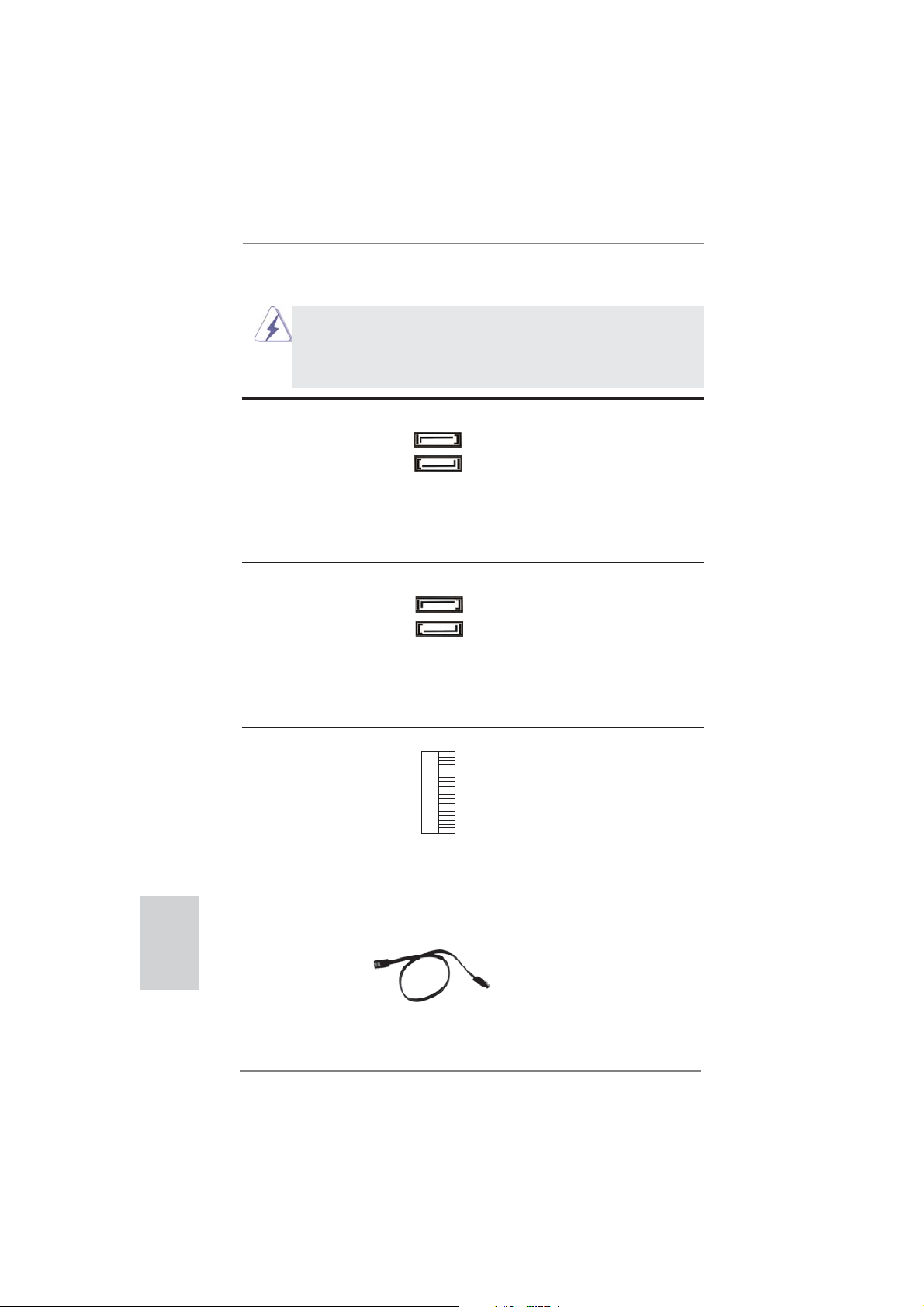
1.4 Collettori e Connettori su Scheda
I collettori ed i connettori su scheda NON sono dei jumper. NON installare cappucci per jumper su questi collettori e connettori. L’installazione
di cappucci per jumper su questi collettori e connettori provocherà
danni permanenti alla scheda madre!
Italiano
Connettori Serial ATA2 Questi due connettori Serial
(SATA_2: vedi p.2 Nr. 4)
(SATA_3: vedi p.2 Nr. 1)
ATA2 (SATA2) supportano cavi
dati SATA per dispositivi di
immagazzinamento interni.
L’interfaccia SATA2 attuale
SATA_2
SATA_3
permette velocità di
trasferimento dati fi no a 3.0
Gb/s.
Serial ATA3 Connectors Questi due connettori Serial
(SATA3_0: vedi p.2 Nr. 3)
(SATA3_1: vedi p.2 Nr. 2)
ATA3 (SATA3) supportano cavi
dati SATA per dispositivi di
immagazzinamento interni.
L’interfaccia SATA3 attuale
SATA3_0
SATA3_1
permette velocità di
trasferimento dati fi no a 6.0
Gb/s.
Connettore mSATA Questo connettore mSATA può
(vedi p.3 Nr. 23)
essere utilizzato per connettere
una unità SSD (Solid State
Drive) per una periferica di
archiviazione interna.
L’interfaccia attuale mSATA
consente una gamma di
trasferimento dati massima di
3,0 Gb/s.
Cavi dati Serial ATA (SATA) Una o altra estremità del cavo
(Opzionale)
di dati SATA può essere
collegata al disco rigido SATA /
SATA2 / SATA3 o al connettore
di SATA2 / SATA3 su questa
cartolina base.
74
ASRock Z77E-ITX Motherboard
Page 75
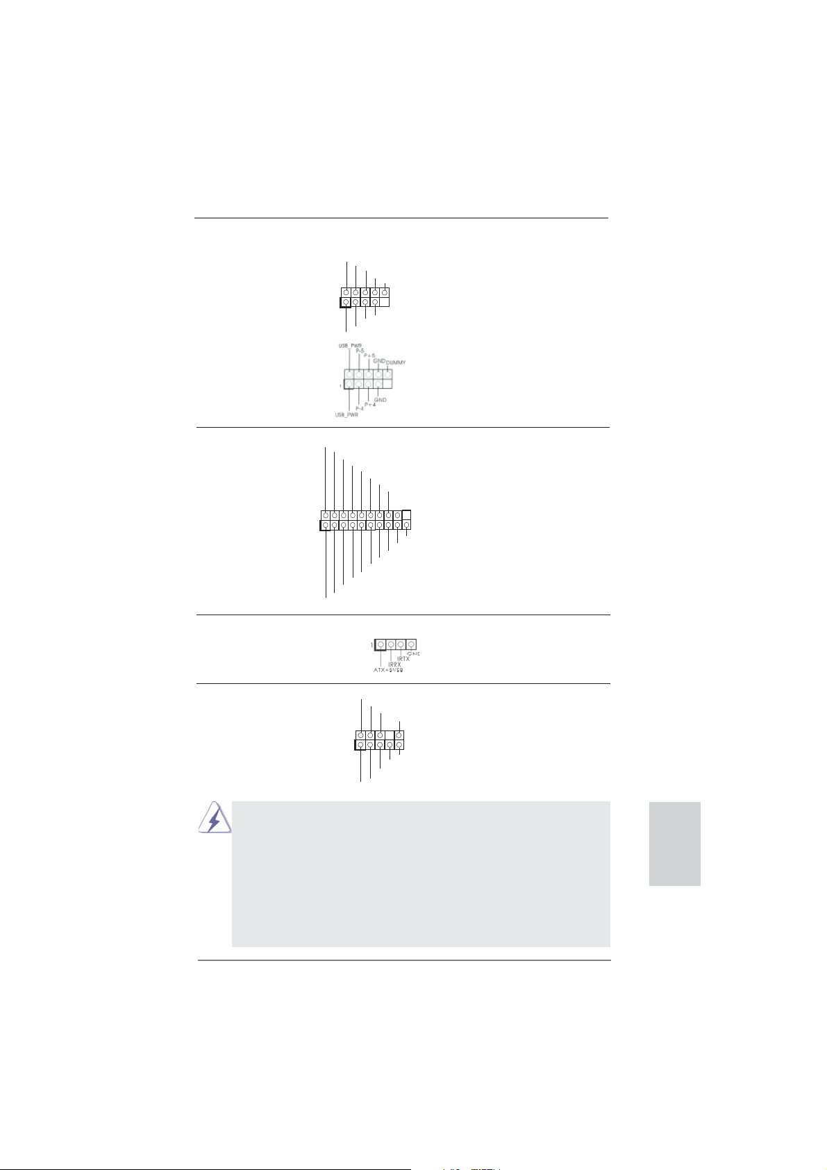
Collettore USB 2.0 Oltre alle due porte USB 2.0
(9-pin USB2_3)
(vedi p.2 Nr. 5)
predefi nite nel pannello I/O, la
scheda madre dispone di due
intestazioni USB 2.0. Ciascuna
intestazione USB 2.0 supporta
due porte USB 2.0.
1
USB_PWR
P-3
P-2
USB_PWR
P+3
P+2
GND
GND
DUMMY
(9-pin USB4_5)
(vedi p.2 Nr. 6)
Collettore USB 3.0 Oltre alle quattro porte USB 3.0
(19-pin USB3_3_4)
(vedi p.2 Nr. 8)
standard del pannello I/O,
questa scheda madre è dotata
di un header USB 3.0 che
IntA_P0_D+
IntA_P0_D-
GND
IntA_P0_SSTX+
IntA_P0_SSTX-
GND
IntA_P0_SSRX+
IntA_P0_SSRX-
Vbus
supporta due porte USB 3.0.
1
Vbus
IntA_P1_SSRX-
IntA_P1_SSRX+
GND
IntA_P1_SSTX-
IntA_P1_SSTX+
GND
IntA_P1_D-
IntA_P1_D+
Connettore modulo infrarosso consumer Questo connettore può essere
(4-pin CIR1)
(vedi p.2 Nr. 7)
Connettore audio sul È un’interfaccia per il cavo del
pannello frontale pannello audio. Che consente
(9-pin HD_AUDIO1)
(vedi p.2 Nr. 19)
1. La caratteristica HDA (High Defi nition Audio) supporta il rilevamento dei
connettori, però il pannello dei cavi sul telaio deve supportare la funzione HDA
(High Defi nition Audio) per far sì che questa operi in modo corretto. Attenersi alle
istruzioni del nostro manuale e del manuale del telaio per installare il sistema.
2. Se si utilizza un pannello audio AC’97, installarlo nell’intestazione audio del
pannello anteriore, come indicato di seguito:
utilizzato per collegare
ricevitore remoto.
GND
PRESENCE#
MIC_RET
OUT_RET
connessione facile e controllo
dei dispositivi audio.
A. Collegare Mic_IN (MIC) a MIC2_L.
B. Collegare Audio_R (RIN) a OUT2_R e Audio_L (LIN) ad OUT2_L.
C. Collegare Ground (GND) a Ground (GND).
1
MIC2_R
MIC2_L
J_SENSE
OUT2_R
OUT2_L
Italiano
ASRock Z77E-ITX Motherboard
75
Page 76

Italiano
D. MIC_RET e OUT_RET sono solo per il pannello audio HD. Non è
necessario collegarli per il pannello audio AC’97.
E. Per attivare il microfono frontale.
Sistema operativo Windows® XP / XP 64-bit:
Selezionare “Mixer”. Selezionare “Recorder” (Registratore). Poi, fare
clic su “FrontMic” (Microfono frontale).
Sistema operativo Windows® 7 / 7 64-bit / VistaTM / VistaTM 64-bit:
Andare alla scheda “FrontMic” (Microfono frontale) del pannello di
controllo Realtek. Regolare la voce “Recording Volume” (Volume
registrazione).
Collettore pannello di sistema Questo collettore accomoda
(9-pin PANEL1)
(vedi p.2 Nr. 17)
Collegare l’interruttore d’alimentazione, l’interruttore di ripristino,
l’indicatore di stato del sistema del pannello frontale del telaio a questo
header in base all’assegnazione dei pin defi nita di seguito. Determinare i
pin positivi e negativi prima di collegare i cavi.
PWRBTN (interruttore d’alimentazione):
RESET (interruttore di ripristino):
PLED (LED alimentazione del sistema):
HDLED (LED attività disco rigido):
diverse funzioni di sistema
pannello frontale.
Va collegato all’interruttore d’alimentazione del pannello frontale del
telaio. Usando l’interruttore d’alimentazione si può confi gurare il modo in
cui si spegne il sistema.
Va collegato all’interruttore di ripristino del pannello frontale del telaio.
Premere l’interruttore di ripristino per riavviare il sistema se il computer si
blocca e non riesce ad eseguire un normale riavvio.
Va collegato all’indicatore di stato d’alimentazione del pannello frontale
del telaio. Il LED è acceso quando il sistema è operativo. Il LED continua
a lampeggiare quando il sistema è in stato di standby S1/S3. Il LED è
spento quando il sistema è in stato di sospensione /ibernazione S4
oppure spento (S5).
Va collegato al LED attività disco rigido del pannello frontale del telaio. Il
LED è acceso quando disco rigido legge e scrive i dati.
Il design del pannello frontale può variare in base ai telai. Il modulo di un
pannello frontale può consistere di: interruttore d’alimentazione,
interruttore di ripristino, LED d’alimentazione, LED attività disco rigido,
casse, eccetera. Quando si collega il modulo del pannello frontale a
questo header, assicurarsi che l’assegnazione dei fi li e dei pin sia fatta
corrispondere in modo appropriato.
76
ASRock Z77E-ITX Motherboard
Page 77
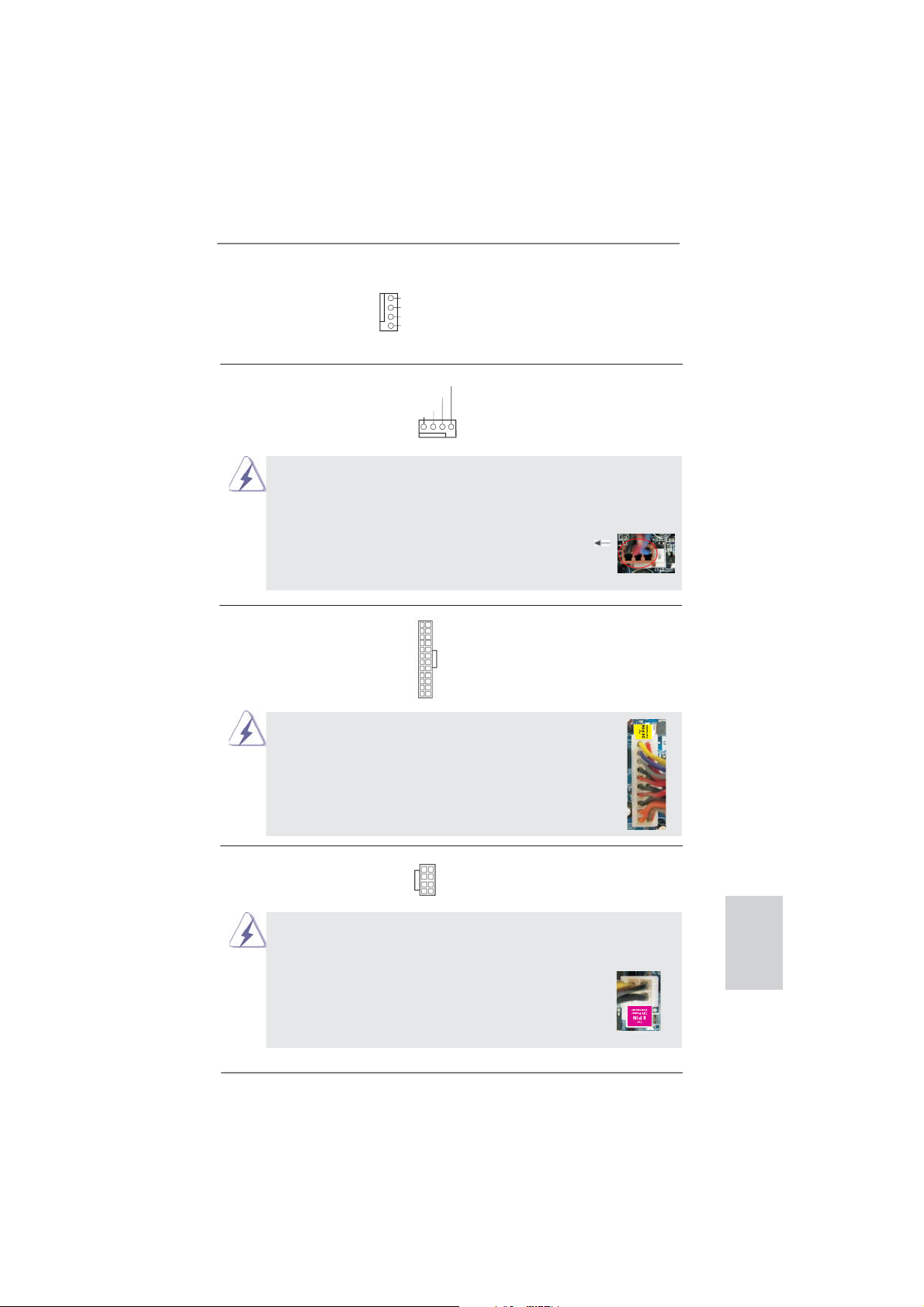
Collettori Chassis ventola Collegare i cavi della ventola ai
(4-pin CHA_FAN1)
(vedi p.2 Nr. 13)
corrispondenti connettori
facendo combaciare il cavo
GND
+12V
CHA_FAN_SPEED
FAN_SPEED_CONTROL
nero col pin di terra.
Connettore ventolina CPU Collegare il cavo della ventolina
(4-pin CPU_FAN1)
(vedi p.2 Nr. 10)
CPU a questo connettore e far
combaciare il fi lo nero al pin
terra.
FAN_SPEED_CONTROL
CPU_FAN_SPEED
+12V
GND
1 2 3 4
Sebbene la presente scheda madre disponga di un supporto per ventola CPU a 4
piedini (ventola silenziosa), la ventola CPU a 3 piedini è in grado di funzionare
anche senza la funzione di controllo della velocità della ventola. Se si intende
collegare la ventola CPU a 3 piedini al connettore della ventola CPU su questa
scheda madre, collegarla ai piedini 1-3.
Piedini 1-3 collegati
Installazione della ventola a 3 piedini
Connettore alimentazione ATX Collegare la sorgente
(24-pin ATXPWR1)
(vedi p.2 Nr. 16)
Con questa scheda madre, c’è in dotazione un
d’alimentazione ATX a questo
connettore.
12 124
13
12
24
connettore elettrico ATX a 24 pin, ma può funzionare lo
stesso se si adotta un alimentatore ATX a 20 pin. Per
usare l’alimentatore ATX a 20 pin, collegare l’alimentatore
con il Pin 1 e il Pin 13.
Installazione dell’alimentatore ATX a 20 pin
1
13
Connettore ATX 12 V Collegare un alimentatore ATX
(8-pin ATX12V1)
(vedi p.2 Nr. 22)
12 V a questo connettore.
5 1
8 4
Sebbene questa schedamadre fornisca un connettore elettrico 8-pin ATX 12V,
l‘unita‘ puo‘ ancora essere funzionante se viene utilizzata una fornitura elettrica
tradizionale a 4-pin ATX 12V. Per usare tale fornitura elettrica 4-pin ATX 12V,
prego collegare la presa elettrica al Pin 1 e Pin 5.
Installazione elettrica 4-Pin ATX 12V
5 1
8 4
ASRock Z77E-ITX Motherboard
Italiano
77
Page 78

2. Informazioni sul BIOS
La Flash Memory sulla scheda madre contiene le Setup Utility. Quando si avvia il
computer, premi <F2> o <Del> durante il Power-On-Self-Test (POST) della Setup
utility del BIOS; altrimenti, POST continua con i suoi test di routine. Per entrare il
BIOS Setup dopo il POST, riavvia il sistema premendo <Ctl> + <Alt> + <Delete>, o
premi il tasto di reset sullo chassis del sistema. Per informazioni più dettagliate circa
il Setup del BIOS, fare riferimento al Manuale dell’Utente (PDF fi le) contenuto nel cd
di supporto.
3. Software di supporto e informazioni su CD
Questa scheda madre supporta vari sistemi operativi Microsoft® Windows®: 7 /
7 64-bit / VistaTM / Vista
scheda madre contiene i driver e utilità necessari a potenziare le caratteristiche
della scheda.
Inserire il CD di supporto nel lettore CD-ROM. Se la funzione “AUTORUN” è attivata
nel computer, apparirà automaticamente il Menù principale. Se il Menù principale
non appare automaticamente, posizionarsi sul fi le “ASSETUP.EXE” nel CESTINO
del CD di supporto e cliccare due volte per visualizzare i menù.
TM
64-bit / XP / XP 64-bit. Il CD di supporto a corredo della
Italiano
78
ASRock Z77E-ITX Motherboard
Page 79

1. Introducción
Gracias por su compra de ASRock Z77E-ITX placa madre, una placa de confi anza
producida bajo el control de calidad estricto y persistente. La placa madre provee
realización excelente con un diseño robusto conforme al compromiso de calidad y
resistencia de ASRock.
Esta Guía rápida de instalación contiene una introducción a la placa base y una
guía de instalación paso a paso. Puede encontrar una información más detallada
sobre la placa base en el manual de usuario incluido en el CD de soporte.
Porque las especifi caciones de la placa madre y el software de BIOS
podrían ser actualizados, el contenido de este manual puede ser cambiado
sin aviso. En caso de cualquier modifi cación de este manual, la versión
actualizada estará disponible en el website de ASRock sin previo aviso.
También encontrará las listas de las últimas tarjetas VGA y CPU soportadas
en la página web de ASRock.
Website de ASRock http://www.asrock.com
Si necesita asistencia técnica en relación con esta placa base, visite nuestra
página web con el número de modelo específi co de su placa.
www.asrock.com/support/index.asp
1.1 Contenido de la caja
Placa base ASRock Z77E-ITX
(Factor forma Mini-ITX: 17,0 cm x 17,0 cm, 6,7” x 6,7”)
Guía de instalación rápida de ASRock Z77E-ITX
CD de soporte de ASRock Z77E-ITX
Dos cables de datos Serial ATA (SATA) (Opcional)
Una Antena WiFi de 2,4 GHz de ASRock (Opcional)
Un conversor DVI-D-Sub (Opcional)
Una protección I/O
ASRock le recuerda...
Para mejorar el rendimiento en Windows® 7 / 7 64 bits / Vista
64 bits, es recomendable establecer la opción del BIOS de la confi gura-
ción de almacenamiento en el modo AHCI. Para obtener detalles sobre
la confi guración del BIOS, consulte el “Manual del usuario” que se en-
cuentra en nuestro CD de soporte.
TM
/ VistaTM
ASRock Z77E-ITX Motherboard
Español
79
Page 80

Español
1.2 Especificación
Plataforma - Factor forma Mini-ITX: 17,0 cm x 17,0 cm, 6,7” x 6,7”
- Diseño de condensadores de oro de calidad superior
(condensadores de polímero conductor de alta calidad de
fabricación 100% japonesa)
Procesador - Admite procesadores Intel
generación en el paquete LGA1155
- Diseño de alimentación digital
- Diseño de fases de potencia 6 + 2
- Admite la tecnología Intel
- Admite procesador desbloqueado de la serie K
- Admite tecnología Hyper Threading (ver ATENCIÓN 1)
- Admite las tecnologías Intel
con la CPU Intel® Ivy Bridge
Chipset - Intel® Z77
Memoria - Soporte de Tecnología de Memoria de Doble Canal
(ver ATENCIÓN 2)
- 2 x DDR3 DIMM slots
- Apoya DDR3 2800+(OC)/2400(OC)/2133(OC)/1866(OC)/
1600/1333/1066 non-ECC, memoria de un-buffered
- Máxima capacidad de la memoria del sistema: 16GB
(vea ATENCIÓN 3)
- Compatible con Intel
Ranuras de - 1 x ranura PCI Express 3.0 x16 (PCIE1: modo x16)
Expansión (vea ATENCIÓN 4)
* PCIE 3.0 solamente se admite con una CPU Intel
Bridge. Con una CPU Intel® Sandy Bridge, solamente
admite PCIE 2.0.
- 1 x Ranura de mini-PCI Express: para el módulo WiFi
VGA OnBoard * Los efectos visuales incorporados con gráfi cos de alta
defi nición Intel® y las salidas VGA sólo se soportan con
procesadores con GPU integrada.
- Admite Intel
®
HD Graphics Built-in Visuals: Intel® Quick Sync
Video 2.0, Intel® InTruTM 3D, Intel® Clear Video HD
Technology, Intel
®
InsiderTM, Intel® HD Graphics 2500/4000
- Pixel Shader 5.0, DirectX 11 con CPU Intel® Ivy Bridge, Pixel
Shader 4.1, DirectX 10.1 con CPU Intel® Sandy Bridge
- 1760MB de Memoria máxima compartida (vea ATENCIÓN 5)
- Multi opciones de salida VGA: DVI, HDMI, DisplayPort y
D-Sub con convertidor DVI a D-Sub (vea ATENCIÓN 6)
®
CoreTM i7 / i5 / i3 de la 3ª y 2ª
®
Turbo Boost 2.0 Technology
®
Rapid Start y Smart Connect
®
Extreme Memory Profi le (XMP)1.3/1.2
®
Ivy
80
ASRock Z77E-ITX Motherboard
Page 81

- Admite HDMI 1.4a con una resolución máxima de 1920x1200
a 60 Hz
- Admite DVI con una resolución máxima de 1920x1200 a 60
Hz
- Admite DisplayPort con una resolución máxima de
2560x1600 a 60 Hz
- Admite D-Sub con una resolución máxima de 2048x1536 a
75 Hz
- Admite Sincronización automática entre audio y vídeo, Deep
Color (12 bpc), xvYCC y HBR (audio de alta tasa de bits) con
HDMI (se necesita un monitor compatible con HDMI)
(ver ATENCIÓN 7)
- Admite la función HDCP con puertos DVI, HDMI y
DisplayPort
- Apoya la reproducción de Blu-rayo de 1080p (BD) / HD-DVD
con puertos DVI, HDMI y DisplayPort
Audio - 7.1 CH HD Audio con Protección de Contenido
(Realtek ALC898 Audio Codec)
- Compatible con audio Blu-ray de alta calidad
- Compatible con THX TruStudio
TM
LAN - PCIE x1 Gigabit LAN 10/100/1000 Mb/s
- Broadcom BCM57781
- Soporta Wake-On-LAN
- Compatible con Ethernet 802.3az de bajo consumo
energético
- Compatible con PXE
LAN inalámbrica Módulo WiFi-802.11n
- 300 Mbps IEEE 802.11n / 54 Mbps IEEE 802.11g / 11 Mbps
IEEE 802.11b
- Admite el modo de estación (modo Infraestructura y mod
Ad-hoc)
Entrada/Salida de I/O Panel
Panel Trasero - 2 x Puertos de antena
- 1 x puerto de teclado/ratón PS/2
- 1 x puerto DVI-I
- 1 x puerto HDMI
- 1 x DisplayPort
- 1 x puerto de salida óptica SPDIF
- 2 x puertos USB 2.0 predeterminados
- 1 x Conector eSATA2
- 4 x puertos USB 3.0 predeterminados
- 1 x Puerto LAN RJ-45 con LED (LED de ACCIÓN/ENLACE y
ASRock Z77E-ITX Motherboard
Español
81
Page 82

Español
82
LED de VELOCIDAD)
- 1 x conmutador de borrado de memoria CMOS con
indicador LED
- Conexión de audio: Altavoz trasero / Central / Bajos /
Entrada de línea / Altavoz frontal / Micrófono
(ver ATENCIÓN 8)
SATA 3 - 2 x conectores SATA3 de 6,0 Gb/s con funciones RAID
(RAID 0, RAID 1, RAID 5, RAID 10, Intel Rapid Storage y
tecnología Intel Smart Response), NCQ, AHCI y de Hot Plug
(conexión en caliente)
USB 3.0 - 2 x puertos USB 3.0 traseros de Intel® Z77, compatible con
USB 1.0/2.0/3.0 de hasta 5 GB/s
- 2 x puertos USB 3.0 traseros de ASMedia ASM1042
compatible con USB 1.0/2.0/3.0 de hasta 5 GB/s
- 1 x cabecera USB 3.0 delantera (compatible con 2 puertos
USB 3.0) de Intel
®
Z77, compatible con USB 1.0/2.0/3.0 de
hasta 5 GB/s
Conectores - 2 x conexiones SATA2, admiten una velocidad de
transferencia de datos de hasta 3,0Gb/s, soporta RAID (RAID
0, RAID 1, RAID 5, RAID 10, Intel Rapid Storage y tecnología
Intel Smart Response), NCQ, AHCI y de Hot Plug (conexión
en caliente)
- 1 x conector mSATA 3.0 Gb/s (conector de unidad de estado
sólido), soporta RAID (RAID 0, RAID 1, RAID 5, RAID 10,
Tecnología almacenamiento rápido de Intel y Tecnología de
respuesta rápida de Intel), NCQ, funciones AHCI y de
tamaño completo de mini-PCI Express módulos
- 2 x conexiones SATA3, admiten una velocidad de
transferencia de datos de hasta 6,0Gb/s
- 1 x
Base de conexiones del módulo de infrarrojos para el
consumidor
- Conector de ventilador de CPU / chasis
- 24-pin cabezal de alimentación ATX
- 8-pin conector de ATX 12V power
- Conector de audio de panel frontal
- 2 x Cabezal USB 2.0 (admite 4 puertos USB 2.0 adicionales)
- 1 x Cabezal USB 3.0 (admite 2 puertos USB 3.0 adicionales)
BIOS - 64Mb AMI BIOS legal UEFI AMI compatible con GUI
- Soporta “Plug and Play”
- ACPI 1.1 compliance wake up events
- Soporta “jumper free”
- Soporta SMBIOS 2.3.1
ASRock Z77E-ITX Motherboard
Page 83

- Múltiple ajuste de CPU Core, IGPU, DRAM, VCCSA Voltage
CD de soport - Controladores, utilidades, software de antivirus (versión de
prueba), Prueba de CyberLink MediaEspresso 6.5, Conjunto
multimedia ASRock MAGIX - OEM
Característica - ASRock Extreme Tuning Utility (AXTU) (vea ATENCIÓN 9)
Única - ASRock Instant Boot
- ASRock Instant Flash (vea ATENCIÓN 10)
- ASRock APP Charger (vea ATENCIÓN 11)
- ASRock SmartView (vea ATENCIÓN 12)
- ASRock XFast USB (vea ATENCIÓN 13)
- ASRock XFast LAN (vea ATENCIÓN 14)
- ASRock XFast RAM (vea ATENCIÓN 15)
- ASRock Crashless BIOS (vea ATENCIÓN 16)
- ASRock OMG (Online Management Guard)
(vea ATENCIÓN 17)
- ASRock Internet Flash (vea ATENCIÓN 18)
- Lucid Virtu Universal MVP (vea ATENCIÓN 19)
* Lucid Virtu Universal MVP sólo se soporta con
procesadores con GPU integrada.
- Amplifi cador Híbrido:
- Stepless control de frecuencia de CPU
(vea ATENCIÓN 20)
- ASRock U-COP (vea ATENCIÓN 21)
- Protección de Falla de Inicio (B.F.G..)
- Indicador LED nocturno
Monitor - Sensibilidad a la temperatura del procesador
Hardware - Sensibilidad a la temperatura de la placa madre
- Taquímetros de los ventiladores del procesador y del CPU
- Taquímetros de los ventiladores del procesador y del chasis
- Ventilador silencioso del procesador y el chasis (ajuste
automático de la velocidad del ventilador del chasis en
función de la temperatura del procesador)
- Control de ajuste de la velocidad del ventilador de la CPU /
chasis
- Monitor de Voltaje: +12V, +5V, +3.3V, Vcore
OS - En conformidad con Microsoft
®
Windows® 7 / 7 64 bits /
VistaTM / VistaTM 64 bits / XP / XP 64 bits (vea ATENCIÓN 22)
Certifi caciones - FCC, CE, WHQL
- Cumple con la directiva ErP/EuP (se requiere una fuente de
alimentación que cumpla con la directiva ErP/EuP)
(vea ATENCIÓN 23)
Español
ASRock Z77E-ITX Motherboard
83
Page 84

Español
* Para más información sobre los productos, por favor visite nuestro sitio web:
http://www.asrock.com
ADVERTENCIA
Tenga en cuenta que hay un cierto riesgo implícito en las operaciones de aumento
de la velocidad del reloj, incluido el ajuste del BIOS, aplicando la tecnología de
aumento de velocidad liberada o utilizando las herramientas de aumento de
velocidad de otros fabricantes. El aumento de la velocidad puede afectar a la
estabilidad del sistema e, incluso, dañar los componentes y dispositivos del sistema.
Esta operación se debe realizar bajo su propia responsabilidad y Ud. debe asumir
los costos. No asumimos ninguna responsabilidad por los posibles daños causados
por el aumento de la velocidad del reloj.
ATENCIÓN !
1. Por favor consulte página 47 del Manual del Usuario en el soporte CD
sobre la confi guración de Hyper-Threading Technology.
2. Esta placa base soporta Tecnología de Memoria de Doble Canal. Antes
de implementar la Tecnología de Memoria de Doble Canal, asegúrese de
leer la guía de instalación de módulos de memoria en la página 19 para
su correcta instalación.
3. Debido a las limitaciones del sistema, el tamaño real de la memoria debe
ser inferior a 4GB para que el sistema pueda funcionar bajo Windows
7 / VistaTM / XP. Para equipos con Windows® OS con CPU de 64-bit, no
existe dicha limitación. Puede usar ASRock XFast RAM para utilizar la
memoria que no puede usar Windows
®
.
4. Además, solamente la ranura PCIE1 admite la velocidad Gen 3. Para
conseguir que PCI Express funcione a una velocidad Gen 3, debe instalar la CPU Ivy Bridge. Si instala la CPU Sandy Bridge, PCI Express
solamente funcionará a velocidad PCI Express Gen 2.
5. El tamaño de la memoria compartido máximo es defi nido por el vendedor
del chipset y está conforme al cambio. Por favor compruebe el Web site
®
de Intel
para la información más última.
6. Puede elegir entre dos de los tres monitores solamente. Los monitores DVI, HDMI y DisplayPort no se pueden habilitar al mismo tiempo.
Además, con el adaptador DVI a HDMI, el puerto DVI puede admitir las
mismas funciones que el puerto HDMI.
7. Las funciones xvYCC y Deep Color solamente se admiten con el sistema
operativo Windows
®
7 de 64 bits/ 7. El modo Deep Color solamente se
habilitará si la pantalla admite 12 bpc en EDID. HBR se admite en Windows® 7 64 bits / 7 / VistaTM 64 bits / VistaTM.
8. Para la entrada de micrófono, esta placa madre ofrece soporte para
modos estéreo y mono. Para salida de audio, este placa madre ofrece
soporte para modos de 2 canales, 4 canales, 6 canales y 8 canales.
Consulte la tabla en la página 4 para una conexión correcta.
®
84
ASRock Z77E-ITX Motherboard
Page 85

9. ASRock Extreme Tuning Utility (AXTU) es una herramienta todo en uno
que permite realizar ajustes precisos en diferentes funciones del sistema
mediante una interfaz sencilla, que incluye supervisión de hardware,
control de ventiladores, función de aumento de la velocidad del reloj,
DNA OC y IES. La función de supervisión de hardware, muestra las
principales lecturas del sistema. La función de control de los
ventiladores, muestra la velocidad y la temperatura de los ventiladores y
permite ajustarlas. La función de aumento de la velocidad del reloj,
permite aumentar la frecuencia de la CPU para conseguir un rendimiento
óptimo del sistema. La función DNA OC permite guardar la confi guración
OC como un perfi l y compartirla con sus amigos. Después, sus
amistados pueden cargar el perfi l OC en sus propios sistemas para
obtener la misma confi guración OC. En el protector de energía
inteligente (IES, Intelligent Energy Saver), el regulador de voltaje puede
reducir el número de fases de salida para mejorar la efi ciencia cuando
los núcleos de la CPU están inactivos sin que el rendimiento de cálculo
disminuya. Visite nuestro sitio Web para obtener los procedimientos de
funcionamiento de ASRock Extreme Tuning Utility (AXTU).
Sitio Web de ASRock: http://www.asrock.com
10. ASRock Instant Flash es una utilidad de programación del BIOS que
se encuentra almacenada en la memoria Flash ROM. Esta sencilla herramienta de actualización de BIOS le permitirá actualizar el BIOS del
sistema sin necesidad de acceder a ningún sistema operativo, como
MS-DOS o Windows
<F6> durante la fase POST o pulsar <F2> para acceder al menú de
confi guración del BIOS y a la utilidad ASRock Instant Flash. Ejecute esta
herramienta y guarde el archivo correspondiente al sistema BIOS nuevo
en su unidad fl ash USB, unidad de disco fl exible o disco duro para poder
actualizar el BIOS con sólo pulsar un par de botones, sin necesidad de
preparar un disco fl exible adicional ni utilizar complicadas utilidades de
programación. Recuerde que la unidad fl ash USB o disco duro utilizado
debe disponer del sistema de archivos FAT32/16/12.
11. Si desea una forma más rápida y menos limitada de cargar sus dispositivos de Apple; como por ejemplo iPhone, iPad o iPod Touch, ASRock
ha creado una fantástica solución para usted: ASRock APP Charger.
Simplemente mediante la instalación del controlador de APP Charger,
podrá cargar su iPhone de forma mucho más rápida que antes, hasta un
40%, desde su equipo. ASRock APP Charger le permite cargar de forma
rápida muchos dispositivos de Apple simultáneamente e incluso podrá
continuar la carga cuando su PC entre en modo de espera (S1), suspendido en RAM (S3), modo de hibernación (S4) o se apague (S5). Una vez
instalado el controlador de APP Charger, podrá disfrutar fácilmente de
una fantástica carga sin precedentes.
Sitio web de ASRock: http://www.asrock.com/Feature/AppCharger/index.
asp
®
. Gracias a esta utilidad, sólo necesitará pulsar
Español
ASRock Z77E-ITX Motherboard
85
Page 86

Español
12. SmartView, una nueva función el explorador de Internet, es la página de
inicio inteligente para IE que combina los sitios Web más visitados, su
historial, sus amigos de Facebook y su fuente de noticias en una vista
mejorada para disfrutar de una experiencia en Internet más personal.
Las placas base ASRock están exclusivamente equipadas con la utilidad
SmartView que le ayuda a seguir en contacto con sus amigos sobre la
marcha. Para utilizar la función SmartView asegúrese de que la versión
de su sistema operativo es Windows
bits y que la versión de su explorador es IE8. Sitio Web de ASRock:
http://www.asrock.com/Feature/SmartView/index.asp
13. ASRock XFast USB puede aumentar el rendimiento de los dispositivos
de almacenamiento USB. El rendimiento depende de las propiedades del
dispositivo.
14. ASRock XFast LAN proporciona un acceso a Internet más rápido, que
incluye las ventajas que se indican a continuación. Priorización de
aplicaciones LAN: Puede confi gurar la prioridad de las aplicaciones de
forma ideal y/o agregar nuevos programas. Menor latencia en los juegos:
Después de aumentar la prioridad de los juegos en línea, se puede re ducir la latencia en los mismos. Gestionar el tráfi co: Puede ver vídeo en
alta defi nición de Youtube y descargar archivos simultáneamente. Análi-
sis de sus datos en tiempo real: Con la ventana de estado, puede
reconocer fácilmente qué transmisiones en secuencias se están trans-
fi riendo actualmente.
15 ASRock XFast RAM es una nueva función incluida en ASRock Extreme
Tuning Utility (AXTU)
no se puede utilizar con procesadores de 32 bits en sistemas operativos
Windows®. ASRock XFast RAM acorta el tiempo de carga de los sitios
Web visitados con anterioridad, lo que permite navegar por Internet
mucho más rápido que nunca. Además, también aumenta la velocidad
de Adobe Photoshop 5 veces. Otra ventaja de ASRock XFast RAM es
que reduce la frecuencia de acceso a las unidades de estado sólido (SSD)
o las unidades de disco duro (HDD), lo que prolonga el período de vida
útil de las mismas.
16. ASRock Crashless BIOS le permite a los usuarios actualizar su BIOS sin
miedo de que ocurra un fallo. Si ocurre una interrupción en el suministro
de energía durante el proceso de actualización del BIOS, ASRock Crash-
less BIOS fi nalizará de manera automática el proceso de actualización
una vez se restablezca en suministro de energía. Tome en cuenta que
los archivos del BIOS deben colocarse en el directorio raíz de su disco
USB. Sólo los puertos USB 2.0 soportan esta función.
17. Los administradores pueden establecer cortes de acceso a Internet o
acceso restringido a Internet en horarios especifi cados mediante OMG.
Puede elegir entre las opciones [Diariamente], [Día de la semana] o [En-
tre semana y Fines de semana] y, a continuación, programar las horas
de inicio y fi nalización del acceso a Internet concedido a otros usuarios.
Para impedir que los usuarios no eviten OMG, se necesitan cuentas de
invitado sin permiso para modifi car la fecha y hora del sistema.
. Utiliza completamente el espacio de memoria que
®
7 / 7 64 bits / VistaTM / VistaTM 64
86
ASRock Z77E-ITX Motherboard
Page 87

18. Internet Flash busca actualizaciones de fi rmware de UEFI disponibles
en nuestro servidores. En otras palabras, el sistema puede detectar
automáticamente la última versión de UEFI existente en nuestros servidores y copiarla sin entrar en el sistema operativo Widows. Para poder
habilitar esta función, debe trabajar en un equipo confi gurado con DHCP.
19. VIRTU Universal MVP incluye las funciones básicas de la tecnología
Virtu Universal, que virtualiza la GPU integrada y la GPU discreta para
obtener las mejores de las funcionalidades. También incluye Virtual
TM
Vsync
, que proporciona una calidad visual sin concesiones. Con las
ventajas añadidas de la tecnología HyperFormance, VIRTU Universal
MVP mejora el rendimiento de los juegos reduciendo inteligentemente
las tareas de representación redundantes en el fl ujo entre la CPU, la
GPU y la pantalla.
20. Aunque esta placa base ofrece un control complete, no es recomendable
forzar la velocidad. Las frecuencias de bus de la CPU distintas a las recomendadas pueden causar inestabilidad en el sistema o dañar la CPU.
21. Cuando la temperatura de CPU está sobre-elevada, el sistema va a
apagarse automaticamente. Antes de reanudar el sistema, compruebe
si el ventilador de la CPU de la placa base funciona apropiadamente y
desconecte el cable de alimentación, a continuación, vuelva a conectarlo. Para mejorar la disipación de calor, acuérdese de aplicar thermal
grease entre el procesador y el disipador de calor cuando usted instala
el sistema de PC.
22. ASRock XFast RAM no se admite en Microsoft® Windows® XP / XP 64
bits. Las tecnologías Intel® Smart Connect y puertos Intel® USB 3.0 no se
admite en Microsoft® Windows® VistaTM / VistaTM 64 bits / XP / XP 64 bits.
23. EuP, siglas de Energy Using Product (Producto que Utiliza Energía), es
una disposición regulada por la Unión Europea para establecer el
consumo total de energía de un sistema. Según la disposición EuP, la ali-
mentación de CA total para el sistema completo ha de ser inferior a 1,00W
en modo apagado. Para cumplir con el estándar EuP, se requieren una
placa base y una fuente de alimentación que cumplan con la directiva
EuP. Según las directrices de Intel, una fuente de alimentación que cumpla con la directiva EuP debe satisfacer el estándar, es decir, la efi ciencia
de energía de 5v en modo de espera debería ser mayor del 50% con un
consumo de corriente de 100mA. Para seleccionar una fuente de alimentación que cumpla la directiva EuP, le recomendamos que consulte con
el fabricante de la fuente de alimentación para obtener más detalles.
ASRock Z77E-ITX Motherboard
Español
87
Page 88

1.3 Setup de Jumpers
La ilustración muestra como los jumpers
son confi gurados. Cuando haya un jumper-
cap sobre los pins, se dice gue el jumper
está “Short”. No habiendo jumper cap sobre
los pins, el jumper está “Open”. La ilustración muesta un jumper de 3 pins cuyo
pin 1 y pin 2 están “Short”.
Jumper Setting
Limpiar CMOS
(CLRCMOS1, jumper de 3 pins)
(ver p.2, N. 11)
Nota:
CLRCMOS1 permite borrar los datos de la memoria CMOS. Para borrar los
parámetros del sistema y restablecer la confi guración predeterminada de los mismos,
apague el equipo y desenchufe el cable de alimentación de la toma de corriente
eléctrica. Deje que transcurran 15 segundos y, después, utilice un puente
cortocircuitar los contactos 2 y 3 de CLRCMOS1 durante 5 segundos. No borre
la memoria CMOS justamente después de actualizar el BIOS. Si necesita borrar
la memoria CMOS justamente después de actualizar el BIOS, debe iniciar primero
el sistema y, a continuación, cerrarlo antes de llevar a cabo el borrado de
dicha memoria. Tenga en cuenta que la contraseña, la fecha, la hora, el perfi l
predeterminado del usuario, el GUID 1394 y la dirección MAC solamente se
borrará si la batería CMOS se quita.
Valor predeterminado
Restablecimiento de
la CMOS
para
Español
88
ASRock Z77E-ITX Motherboard
Page 89

1.4 Cabezales y Conectores en Placas
Los conectores y cabezales en placa NO son puentes. NO coloque
las cubiertas de los puentes sobre estos cabezales y conectores. El
colocar cubiertas de puentes sobre los conectores y cabezales provocará un daño permanente en la placa base.
Conexiones de serie ATA2 Estas dos conexiones de
(SATA_2: vea p.2, N. 4)
(SATA_3: vea p.2, N. 1)
serie ATA2 (SATA2) admiten
cables SATA para dispositivos
de almacenamiento internos. La
interfaz SATA2 actual permite
SATA_2
SATA_3
una velocidad de transferencia
de 3.0 Gb/s.
Conexiones de serie ATA3 Estas dos conexiones de
(SATA3_0: vea p.2, N. 3)
(SATA3_1: vea p.2, N. 2)
serie ATA3 (SATA3) admiten
cables SATA para dispositivos
de almacenamiento internos. La
interfaz SATA2 / SATA3 actual
SATA3_0
SATA3_1
permite una velocidad de
transferencia de 6.0 Gb/s.
Conector mSATA Este conector mSATA puede
(vea p.3, N. 23)
usarse con una unidad de
estado sólido (SSD) para un
dispositivo de almacenamiento
interno. La interfaz mSATA
actual permite una
transferencia con una velocidad
de hasta 3,0 Gb/s.
Cable de datos de Cualquier extremo del cable de
serie ATA (SATA) los datos de SATA puede ser
(Opcional)
conectado con el disco duro de
SATA / SATA2 / SATA3 o el
conectador de SATA2 / SATA3
en esta placa base.
ASRock Z77E-ITX Motherboard
Español
89
Page 90

Cabezal USB 2.0 Además de dos puertos USB
(9-pin USB2_3)
(vea p.2, N. 5)
2.0 predeterminados en el
panel de E/S, hay dos bases de
conexiones USB 2.0 en esta
placa base. Cada una de estas
bases de conexiones admite
(9-pin USB4_5)
dos puertos USB 2.0.
1
USB_PWR
P-3
P-2
USB_PWR
P+3
P+2
GND
GND
DUMMY
(vea p.2, N. 6)
Español
90
Cabezal USB 3.0 Además de cuatro puertos 3.0
(19-pin USB3_3_4)
(vea p.2, N. 8)
predeterminados situados en el
panel E/S, encontrará una
cabecera USB 3.0 en esta
IntA_P0_D+
IntA_P0_D-
GND
IntA_P0_SSTX+
IntA_P0_SSTX-
GND
IntA_P0_SSRX+
IntA_P0_SSRX-
Vbus
placa base. Esta cabecera USB
3.0 admiten dos puertos USB
3.0.
1
GND
IntA_P1_D-
IntA_P1_D+
IntA_P1_SSRX+
GND
IntA_P1_SSTX-
IntA_P1_SSTX+
Vbus
IntA_P1_SSRX-
Base de conexiones del módulo de Esta base de conexiones se
infrarrojos para el consumidor puede utilizar para conectar
(4-pin CIR1)
(vea p.2, N. 7)
Conector de audio de Este es una interface para
panel frontal cable de audio de panel frontal
(9-pin HD_AUDIO1)
(vea p.2, N. 19)
Audio.
1. El Audio de Alta Defi nición soporta la detección de conector, pero el
cable de panel en el chasis debe soportar HDA para operar
correctamente. Por favor, siga las instrucciones en nuestro manual y
en el manual de chasis para instalar su sistema.
2. Si utiliza el panel de sonido AC’97, instálelo en la cabecera de sonido
del panel frontal de la siguiente manera:
A. Conecte Mic_IN (MIC) a MIC2_L.
B. Conecte Audio_R (RIN) a OUT2_R y Audio_L (LIN) en OUT2_L.
C. Conecte Ground (GND) a Ground (GND).
receptor remoto.
GND
PRESENCE#
MIC_RET
MIC2_R
MIC2_L
J_SENSE
OUT2_R
OUT_RET
OUT2_L
que permite conexión y control
conveniente de apparatos de
1
ASRock Z77E-ITX Motherboard
Page 91

D. MIC_RET y OUT_RET son sólo para el panel de sonido HD. No
necesitará conectarlos al panel de sonido AC’97.
E. Activación del micrófono frontal.
En sistemas operativos Windows
Seleccione “Mixer” (Mezclador). Seleccione “Recorder” (Grabadora).
A continuación, haga clic en “FrontMic” (Micrófono frontal).
En sistemas operativos Windows
Acceda a la fi cha “FrontMic” (Micrófono frontal) del panel de control
Realtek. Ajuste la posición del control deslizante “Recording Volume”
(Volumen de grabación).
®
XP / XP 64-bit:
®
7 / 7 64-bit / VistaTM / VistaTM 64-bit:
Cabezal de panel de sistema Este cabezar acomoda varias
(9-pin PANEL1)
(vea p.2, N. 17)
Conecte el interruptor de alimentación, el interruptor de restablecimiento
y el indicador de estado del sistema situados en el chasis con esta
cabecera en función de las siguientes asignaciones de contacto. Preste
atención a los contactos positivos y negativos antes de conectar los
cables.
PWRBTN (interruptor de alimentación):
RESTABLECER (interruptor de restablecimiento):
PLED (LED de alimentación del sistema):
HDLED (LED de actividad del disco duro):
dunciones de panel frontal de
sistema.
Conecte el interruptor de encendido situado en el panel frontal del
chasis. Puede confi gurar la forma de apagar su sistema mediante el
interruptor de alimentación.
Conecte el interruptor de restablecimiento situado en el panel frontal del
chasis. Pulse el interruptor de restablecimiento para restablecer el
equipo si se bloquea y no se reinicia con normalidad.
Conecte el indicador de estado de alimentación situado en el panel
frontal del chasis. El LED se enciende cuando el sistema esté en
funcionamiento. El LED parpadea cuando el sistema se encuentre en
estado de suspensión S1/S3. El LED se apaga cuando el sistema se
encuentre en estado de suspensión S4 o se apaga (S5).
Conecte el LED de actividad de disco duro situado en el panel frontal
del chasis. El LED se enciende cuando el disco duro esté leyendo o
escribiendo datos.
Español
Es posible que el diseño del panel frontal varíe en función del chasis. Un
módulo del panel frontal consiste principalmente de interruptor de
alimentación, interruptor de restablecimiento, LED de alimentación, LED
de actividad del disco duro, altavoz, etc. Al conectar el módulo del panel
ASRock Z77E-ITX Motherboard
91
Page 92

frontal del chasis a esta cabecera, asegúrese de que las asignaciones
de cables y las asignaciones de contactos coincidan correctamente.
Conectores de ventilador de chasis Por favor, conecte los cables
(4-pin CHA_FAN1)
(vea p.2, N. 13)
del ventilador a los conectores
GND
+12V
CHA_FAN_SPEED
FAN_SPEED_CONTROL
de ventilador, haciendo coincidir
el cable negro con la patilla de
masa.
Español
Conector del ventilador Conecte el cable del ventilador
de la CPU de la CPU a este conector y
(4-pin CPU_FAN1)
(vea p.2, N. 10)
haga coincidir el cable negro
con el conector de tierra.
FAN_SPEED_CONTROL
CPU_FAN_SPEED
+12V
GND
1 2 3 4
Aunque esta placa base proporciona compatibilidad para un ventilador (silencioso)
de procesador de 4 contactos, el ventilador de procesador de 3 contactos seguirá
funcionando correctamente incluso sin la función de control de velocidad de
ventilador. Si pretende enchufar el ventilador de procesador de 3 contactos en el
conector del ventilador de procesador de esta placa base, conéctelo al contacto
1-3.
Contacto 1-3 conectado
Instalación del ventilador de 3 contactos
Cabezal de alimentación ATX Conecte la fuente de
(24-pin ATXPWR1)
(vea p.2, N. 16)
A pesar de que esta placa base incluye in conector
de alimentación ATX de 24 pins, ésta puede funcionar
alimentación ATX a su cabezal.
12 124
13
12
24
incluso si utiliza una fuente de alimentación ATX de
20 pins tradicional. Para usar una fuente de
alimentación ATX de 20 pins, por favor, conecte su
fuente de alimentación usando los Pins 1 y 13.
Instalación de una Fuente de Alimentación ATX de 20 Pins
1
13
Cabezal de alimentación ATX 12V Conecte la fuente de
(8-pin ATX12V1)
(vea p.2, N. 22)
5 1
8 4
alimentación ATX 12V a su
cabezal.
92
ASRock Z77E-ITX Motherboard
Page 93
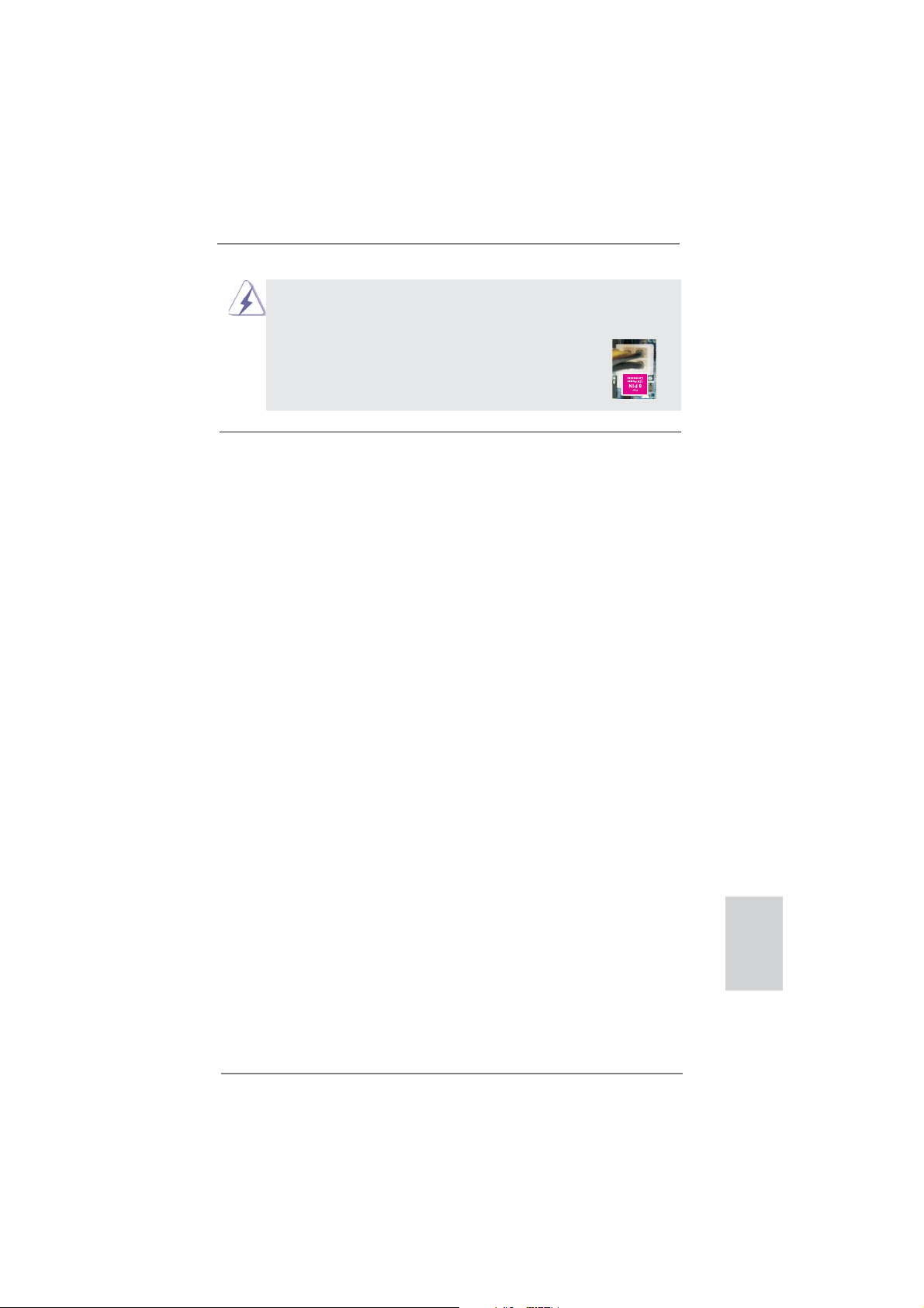
Aunque esta placa base proporciona un conector de energía de 8-pin ATX 12V,
puede todavía trabajar si usted adopta un fuente tradicional de energía de 4-pin
ATX 12V. Para usar el fuente de energía de 4-pin ATX 12V, por favor conecte
su fuente de energía junto con Pin 1 y Pin 5.
5 1
Instalación de Fuente de Energía de 4-Pin ATX 12V
8 4
2. BIOS Información
El Flash Memory de la placa madre deposita SETUP Utility. Durante el Power-Up
(POST) apriete <F2> o <Del> para entrar en la BIOS. Sí usted no oprime ninguna
tecla, el POST continúa con sus rutinas de prueba. Si usted desea entrar en la
BIOS después del POST, por favor reinicie el sistema apretando <Ctl> + <Alt> +
<Borrar>, o apretando el botón Reset en el panel del ordenador. Para información
detallada sobre como confi gurar la BIOS, por favor refi érase al Manual del Usuario
(archivo PDF) contenido en el CD.
3. Información de Software Support CD
Esta placa-base soporta diversos tipos de sistema operativo Windows®: 7 / 7 64
bits / VistaTM / Vista
la placa-base trae todos los drivers y programas utilitarios para instalar y confi gurar
la placa-base. Para iniciar la instalación, ponga el CD en el lector de CD y se desplegará el Menú Principal automáticamente si «AUTORUN» está habilitado en su
computadora.
Si el Menú Principal no aparece automáticamente, localice y doble-pulse en el archivo “ASSETUP.EXE” para iniciar la instalación.
TM
64 bits / XP / XP 64 bits. El CD de instalación que acompaña
ASRock Z77E-ITX Motherboard
Español
93
Page 94
1. Введение
Благодарим вас за покупку материнской платы ASRock Z77E-ITX надежной материнской
платы, изготовленной в соответствии с постоянно предъявляемыми ASRock жесткими
требованиями к качеству. Она обеспечивает превосходную производительность и
отличается отличной конструкцией, которые отражают приверженность ASRock качеству и
долговечности.
Данное руководство по быстрой установке включает вводную информацию о материнской
плате и пошаговые инструкции по ее установке.
можно найти в руководстве пользователя на компакт-диске поддержки.
Спецификации материнской платы и программное обеспечение
BIOS иногда изменяются, поэтому содержание этого руководства
может обновляться без уведомления. В случае любых модификаций
руководства его новая версия будет размещена на веб-сайте ASRock
без специального уведомления. Кроме того, самые свежие
поддерживаемых модулей памяти и процессоров можно найти на
сайте ASRock.
Адрес веб-сайта ASRock http://www.asrock.com
При необходимости технической поддержки по вопросам данной
материнской платы посетите наш веб-сайт для получения
информации об используемой модели.
www.asrock.com/support/index.asp
1.1 Комплектность
Материнская плата ASRock Z77E-ITX
(форм-фактор Mini-ITX: 6,7 x 6,7 дюйма / 17,0 x 17,0 см)
Руководство по быстрой установке ASRock Z77E-ITX
Компакт-диск поддержки ASRock Z77E-ITX
2 x кабель данных Serial ATA (SATA) (дополнительно)
1 x 2,4-ГГц WiFi-антенна ASRock (дополнительно)
1 x DVI-в-D-Sub конвертер (дополнительно)
1 x I/O Щит Группы ввода / вывода
Более подробные сведения о плате
списки
Русский
94
ASRock напоминает...
Для обеспечения максимальной производительности ОС Windows
7 / 7 64-bit / Vista
параметра Storage Configuration (Конфигурация запоминающего
устройства) режим AHCI. Подробные сведения о настройке BIOS см.
в руководстве пользователя на прилагаемом компакт-диске.
TM
/ VistaTM 64-bit рекомендуется в BIOS выбрать для
ASRock Z77E-ITX Motherboard
®
Page 95
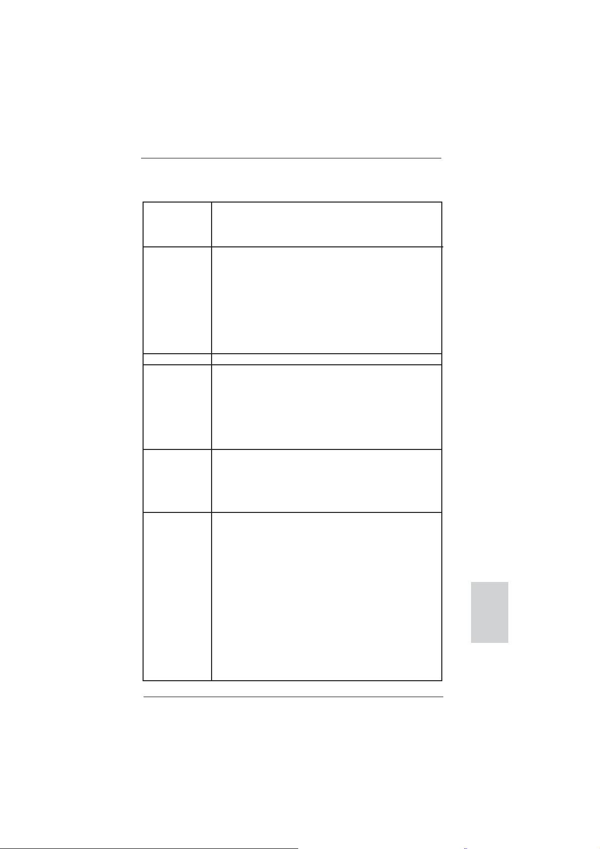
1.2 Спецификации
Платформа - форм-фактор Mini-ITX: 6,7 x 6,7 дюйма / 17,0 x 17,0 см
- Дизайн конденсатора Premium Gold (100% японские
высококачественные конденсаторы на основе проводящих
полимеров)
Процессор - Поддержка процессора Intel
с помощью разъема для процессоров LGA 1155
- Дизайн системы питания DigiPower
- 6 + 2 проектирование фаз питания
- Поддержка технологии Intel
- Поддержка разблокированного ЦП серии K
- Поддержка технологии Hyper-Threading
(см. ОСТОРОЖНО, пункт 1)
- Поддержка технологии Intel® Rapid Start Technology и Smart Connect
Technology с помощью процессора Intel® Ivy Bridge
Набор микросхем - Intel
®
Z77
Память - Поддержка технологии Dual Channel DDR3 Memory Technology
(см. ОСТОРОЖНО, пункт 2)
- 2 x гнезда DDR3 DIMM
- Поддержите DDR3 2800+(OC)/2400(OC)/2133(OC)/1866(OC)/1600/
1333/1066 не- ECC, безбуферная память
- Максимальный объем системной памяти: 16 ГБ
(см. ОСТОРОЖНО, пункт 3)
- поддержка профиля Intel
Гнезда - 1 x слота PCI Express 3.0 x16 (PCIE1: режим x16)
расширения (см. ОСТОРОЖНО, пункт 4)
* PCIE 3.0 поставляется только в комплекте с ЦП Intel® Ivy Bridge. В
комплекте с ЦП Intel® Sandy Bridge поставляется только модель
PCIE 2.0.
- 1 x слот mini-PCI Express: для модуля WiFi
Графика * Встроенный видеоадаптер Intel
поддерживаются только с процессорами, оснащенными
интегрированным графическим процессором.
- Поддержка функций встроенных видеоадаптеров Intel® HD: Intel®
Quick Sync Video 2.0, Intel
HD, Intel® InsiderTM, Intel® HD Graphics 2500/4000
- Pixel Shader 5.0, DirectX 11 с процессором Intel® Ivy Bridge, Pixel
Shader 4.1, DirectX 10.1 с процессором Intel® Sandy Bridge
- Макс. объем разделяемой памяти 1760Мб
(см. ОСТОРОЖНО, пункт 5)
- Несколько VGA-выхода: DVI, HDMI, DisplayPort и D-Sub с
DVI-в-D-Sub конвертер (см. ОСТОРОЖНО, пункт 6)
- Поддержка HDMI 1.4a с максимальным разрешением до 1920х1200
@ 60 Гц
- Поддержка DVI с максимальным разрешением до 1920х1200 @ 60
Гц
®
CoreTM i7 / i5 / i3 3-го и 2-го поколения
®
Turbo Boost 2.0
®
Extreme Memory Profi le (XMP)1.3/1.2
®
HD Graphics и выходы VGA
®
InTruTM 3D, технологии Intel® Clear Video
Русский
ASRock Z77E-ITX Motherboard
95
Page 96

Русский
- Поддержка DisplayPort с максимальным разрешением до 2560х1600
@ 60 Гц
- Поддержка D-Sub с максимальным разрешением до 2048х1536
@ 75 Гц
- Поддержка Auto Lip Sync, Deep Color (12 бит на цветовой канал),
xvYCC и HBR (High Bit Rate Audio) через HDMI (необходим монитор
с разъемом HDMI) (см. ОСТОРОЖНО, пункт 7)
- Поддержка функции HDCP через разъемы DVI, HDMI и DisplayPort
- Подержат Blu-луч 1080p (КОММУТАЦИОННАЯ ДОСКА) /
воспроизведение HD-DVD через разъемы DVI, HDMI и DisplayPort
Аудиосистема - 7.1 CH HD Аудио HD с Довольной
(Кодер-декодер Аудио Realtek ALC898)
- Поддержка Premium Blu-ray audio
- Поддержка технологии THX TruStudio
ЛВС - PCIE x 1 Gigabit LAN 10/100/1000 Mb/s
- Broadcom BCM57781
- поддержка Wake-On-LAN
- Поддержка энергосберегающего интерфейса Ethernet 802.3az
- Поддержка PXE
Беспроводная Модуль WiFi-802.11n
ЛВС - 300 Мбит/с в режиме IEEE 802.11n, 54 Мбит/с в режиме IEEE
802.11g, 11M Мбит/с в режиме IEEE 802.11b
- Поддержка режима станции (инфраструктурный режим или
одноранговый режим)
Разъемы ввода- I/O Panel
вывода на задней - 2 x антенных порта
панели - 1 x порт клавиатуры/мыши PS/2
- 1 x DVI-I порт
- 1 x HDMI порт
- 1 x DisplayPort
- 1 x порт Optical SPDIF Out
- 2 x порта USB 2.0 на задней панели в стандартной конфигурации
- 1 x eSATA2 порт
- 4 x порта USB 3.0 на задней панели в стандартной конфигурации
- 1 x Разъем RJ-45 LAN с светодиодным индикатором (индикатор
ACT/LINK и индикатор SPEED)
- 1 x кнопка Clear CMOS со светодиодом
- Соединитель звуковой подсистемы: тыльная колонка / центральная
/ субвуфер / линейный вход / передняя колонка / микрофон
(см. ПРЕДУПРЕЖДЕНИЕ 8)
SATA 3 - 2 x порта SATA3 со скоростью передачи данных 6,0 Гбит/с, с
аппаратной поддержкой функций RAID (RAID 0, RAID 1, RAID 5,
RAID 10, Intel Rapid Storage и технологии Intel Smart Response),
NCQ, AHCI и горячего подключения
USB 3.0 - 2 x задних порта USB 3.0 на контроллере Intel® Z77 с поддержкой
интерфейсов USB 1.0/2.0/3.0 и скорости передачи данных до
5 Гбит/с
- 2 x задних порта USB 3.0 на контроллере ASMedia ASM1042 с
Защитой
TM
96
ASRock Z77E-ITX Motherboard
Page 97

поддержкой интерфейсов USB 1.0/2.0/3.0 и скорости передачи
данных до 5 Гбит/с
- 1 x передний разъем USB 3.0 (поддерживает 2 порта USB 3.0) на
контроллере Intel® Z77 с поддержкой интерфейсов USB 1.0/
2.0/3.0 и скорости передачи данных до 5 Гбит/с
Колодки и - 2 x разъема SATA2 3,0 Гбит/с, поддержка функций RAID (RAID 0,
плате RAID 1, RAID 5, RAID 10, Intel Rapid Storage и технологии Intel
Smart Response), NCQ, AHCI и горячего подключения
- 1 x разъем mSATA 3.0 ГБ/сек. (разъем твердотельного накопителя),
поддержка RAID (RAID 0, RAID 1, RAID 5, RAID 10, технологии Intel
Rapid Storage и Intel Smart Response Technology), функций NCQ,
AHCI и Полный размер mini-PCI Express модули
- 2 x разъема SATA3 6,0 Гбит/с
- 1 x
- соединитель: CPU/Chassis FAN
- 24-контактный Колодка питания ATX
- 8-контактный Разъем ATX 12 В
- Аудиоразъем передней панели
- 2 x Колодка USB 2.0 (одна колодка для поддержки 4)
дополнительных портов USB 2.0
- 1 x Колодка USB 3.0 (одна колодка для поддержки 2
дополнительных портов USB 3.0)
BIOS - 64Mb AMI UEFI Legal BIOS с поддержкой rpaфичеckoro интеpфeйca
поль зователя
- поддержка “Plug and Play”
- ACPI 1.1, включение по событиям
- поддержка режима настройки без перемычек
- поддержка SMBIOS 2.3.1
- Регулировка напряжений CPU Core, IGPU, DRAM, VCCSA
Компакт- диск - Драйверы, служебные программы, антивирусное программное
поддержки обеспечение (пробная версия), Пробная версия программы
CyberLink MediaEspresso 6.5, ASRock MAGIX Multimedia Suite поставщик
Уникальная - Средство ASRock Extreme Tuning Utility (AXTU)
Особенность (см. ОСТОРОЖНО, пункт 9)
- ASRock Instant Boot
- ASRock Instant Flash (см. ОСТОРОЖНО, пункт 10)
- ASRock APP Charger (см. ОСТОРОЖНО, пункт 11)
- ASRock SmartView (см. ОСТОРОЖНО, пункт 12)
- ASRock XFast USB (см. ОСТОРОЖНО, пункт 13)
- ASRock XFast LAN (см. ОСТОРОЖНО, пункт 14)
- ASRock XFast RAM (см. ОСТОРОЖНО, пункт 15)
- ASRock Crashless BIOS (см. ОСТОРОЖНО,
- ASRock OMG (Online Management Guard)
(см. ОСТОРОЖНО, пункт 17)
- ASRock Internet Flash (см. ОСТОРОЖНО, пункт 18)
- Lucid Virtu Universal MVP (см. ОСТОРОЖНО, пункт 19)
Датчик пользовательского инфракрасного модуля
пункт 16)
Русский
ASRock Z77E-ITX Motherboard
97
Page 98

* Lucid Virtu Universal MVP поддерживается только с процессорами,
оснащенными интегрированными интегрированным графическим
процессором.
- Hybrid Booster:
- плавная настройка частоты процессора
(см. ОСТОРОЖНО, пункт 20)
- ASRock U-COP (см. ОСТОРОЖНО, пункт 21)
- Защита от сбоев загрузки Boot Failure Guard (B.F.G)
- Ночное LED-освещение
Контроль - Датчики температуры процессора
оборудо-вания - Датчики температуры корпуса
- Тахометры вентиляторов процессора FAN
- Тахометры вентиляторов корпуса FAN
- Бесшумный вентилятор ЦП/системного блока (возможность авто
матической настройки скорости вентилятора системного блока в
соответствии с температурой центрального процессора)
- Мультиконтроль скорости вентилятора ЦП/Шасси
- Контроль= напряжения: +12V, +5V, +3.3V, Vcore
Операцион - Совместимость с Microsoft
Поддержка 64-разрядной версии VistaTM / XP / XP 64-bit
(см. ОСТОРОЖНО, пункт 22)
ные системы - FCC, CE, WHQL
Сертификаты - Совместимость с ErP/EuP Ready (требуется блок питания
совместимый с ErP/EuP) (см. ОСТОРОЖНО, пункт 23)
* Для детальной информации продукта, пожалуйста посетите наш вебсайт:
http://www.asrock.com
®
Windows® 7 / 7 64-bit / Vista
TM
/
Русский
ВНИМАНИЕ
Следует понимать, что с оверклокингом связан определенный риск во всех
случаях, включая изменение установок BIOS, применение технологии Untied
Overclocking или использование инструментов оверклокинга сторонних
производителей. Оверклокинг может повлиять на стабильность работы
системы и даже вызвать повреждение входящих в нее компонентов и
устройств. Приступая к оверклокингу, вы полностью берете на себя
связанные с ним риски и расходы. Мы не будем нести ответственность за
любые возможные повреждения в результате оверклокинга.
98
ASRock Z77E-ITX Motherboard
все
Page 99

ОСТОРОЖНО!
1. Информацию об установке параметров гиперпоточной технологии (Hyper-
Threading Technology) вы найдете на стр. 47 Руководства пользователя
на компакт-диске поддержки.
2. Данная материнская плата поддерживает технологию двухканальной
памяти Dual Channel Memory Technology. Перед ее использованием
не забудьте прочитать инструкции по правильной установке модулей
памяти в руководстве по установке (стр. 19).
3. В силу ограничения операционной системы фактическая емкость
памяти может
использования системой Windows® 7 / VistaTM / XP. Таких ограничений нет
для Windows® OS с 64-bit центральным процессором. Технология ASRock
XFast RAM помогает использовать память, которая не используется ОС
Windows
4. Tолько PCIE1 поддерживает скорость Gen 3. Для работы PCI
Express на скорости Gen 3 обязательно установите ЦП Ivy Bridge.
При установке ЦП Sandy Bridge работа PCI Express осуществляется
только на скорости PCI Express Gen 2.
5. Максимальная совместная емкость памяти определена продавцем
микропроцессорного набора и может измениться. Входите в Intel® вебсайт за последние информации, пожалуйста.
6. Вы можете использовать только два разъема из трех для вывода
изображения одновременно. Задействовать сразу три подключения -
DVI, HDMI и DisplayPort - невозможно. При помощи адаптера DVI-toHDMI порт DVI будет поддерживать те же функции, что и HDMI.
7. Функции xvYCC и Deep Color поддерживаются только в Windows
бит / 7. Функция Deep Color будет включена только в том случае, если
монитор поддерживает функцию EDID (12-битные цветовые каналы).
Функция HBR поддерживается только в Windows
бит / Vista
8. Поддерживается работа микрофонного входа в режимах моно и
стерео. Поддерживаются 2-, 4-, 6- и 8-канальный режимы вывода звука.
Соответствующие схемы подключения описаны на стр. 4.
9. Служебная программа ASRock Extreme Tuning Utility (AXTU) – это
универсальное средство тонкой настройки различных функций системы
с удобным и понятным интерфейсом, включающая разделы Hardware
Monitor (Наблюдение за оборудованием), Fan Control (Управление
вентилятором), Overclocking («Разгон» процессора), OC DNA (Параметры
«разгона») and IES (Автоматическое энергосбережение). В разделе
Hardware Monitor (Наблюдение за оборудованием) отображаются
основные характеристики аппаратных средств системы. В разделе Fan
Control (Управление вентилятором) отображается скорость вентилятора
и температура, которые
(«Разгон» процессора) можно увеличить рабочую частоту ЦПУ, чтобы
добиться оптимальной производительности системы. В разделе OC
быть меньше 4Гб для обеспечения резервного места для
®
.
®
TM
.
7 64-бит / 7 / VistaTM 64-
можно регулировать. В разделе Overclocking
®
7 64-
Русский
ASRock Z77E-ITX Motherboard
99
Page 100

Русский
DNA (Параметры «разгона») можно сохранить настройки «разгона»
процессора в виде профиля, который потом можно предложить для
использования своим друзьям. Друзья смогут загрузить профиль
«разгона» на свои компьютеры и получить аналогичный результат. В
разделе IES (Автоматическое энергосбережение) можно настроить
регулятор напряжения так, что он будет уменьшать количество
работающих линий питания, чтобы поднять КПД
системы без ущерба для
ее производительности во время простоя ядер ЦПУ. Чтобы узнать, как
работать с программой ASRock Extreme Tuning Utility (AXTU), посетите
наш сайт в Интернете. Адрес сайта ASRock: http://www.asrock.com
10. ASRock Instant Flash – программа для прошивки BIOS, встроенная в Flash
ROM. Данное средство для обновления BIOS умеет работать без входа в
операционные системы, вроде MS-DOS или Windows
®
. Чтобы запустить
программу достаточно нажать <F6> во время самотестирования системы
(POST) или войти в BIOS при помощи кнопки <F2> и выбрать пункт ASRock Instant Flash через меню. Запустите программу и сохраните новый
BIOS на USB-флэшку, дискету или жесткий диск. После этого вы сможете
оперативно обновить BIOS, без необходимости подготовки
дополнительной дискеты, без установки программы прошивки. Имейте в
виду
, что USB-флэшка или винчестер должны использовать файловую
систему FAT32/16/12.
11. Если вы хотите быстрее и без ограничений заряжать свои устройства
Apple, например iPhone, iPad и iPod Touch, компания ASRock
приготовила отличное решение для вас – ASRock APP Charger. Просто
установив драйвер APP Charger, вы сможете заряжать iPhone от
компьютера намного быстрее, ускорение составит до 40%. ASRock
APP Charger позволяет быстро заряжать несколько устройств Apple
одновременно и даже поддерживает непрерывную
зарядку, когда
компьютер переходит в режим ожидания (S1), режим ожидания с
сохранением данных в ОЗУ (S3), режим гибернации (S4) или режим
выключения (S5). Установив драйвер APP Charger, вы испытаете
небывалое удобство зарядки.
Веб-сайт ASRock: http://www.asrock.com/Feature/AppCharger/index.asp
12.
SmartView — это интеллектуальная стартовая страница для браузера
IE, на которой отображаются наиболее посещаемые веб-сайты, история
посещений, друзья в Facebook и обновляемые потоки новостей.
Эта новая функция обеспечивает более удобное использование
возможностей Интернета. Системные платы ASRock эксклюзивно
снабжаются программой SmartView, помогающей поддерживать связь
с друзьями. Программа SmartView работает в ОС Windows
TM
Vista
/ VistaTM 64 bit и браузере IE8.
®
7 / 7 64 bit /
Веб-сайт ASRock: http://www.asrock.com/Feature/SmartView/index.asp
13. Функция ASRock XFast USB увеличивает скорость работы устройств
USB. Рост скорости зависит от устройства.
100
ASRock Z77E-ITX Motherboard
 Loading...