

Page 1

Page 2
Contact Information
If you need to contact ASRock or want to know more about ASRock, you’re
welcome to visit ASRock’s website at http://ww w.asrock.com; or you may contact
your dealer for further information. For technical questions, please submit a
support request form at https://event.asrock.com/tsd.asp
ASRock Incorporation
e-mail: info@asrock.com.tw
ASRock EUROPE B.V.
e-mail: sales@asrock.nl
ASRock America, Inc.
e-mail: sales@asrockamerica.com
Scan the QR code to view more manuals and documents.
Page 3

Contents
Chapter 1 Introduction 1
1.1 Package Contents 1
1.2 Specications 2
1.3 Motherboard Layout 6
1.4 I/O Panel 8
1.5 Block Diagram 10
Chapter 2 Installation 11
2.1 Installing the CPU 12
2.2 Installing the CPU Fan and Heatsink 15
2.3 Installing Memory Modules (DIMM)
2.4 Connecting the Front Panel Header 26
2.5 Installing the Motherboard 27
2.6 Installing SATA Drives 28
2.7 Installing a Graphics Card 30
2.8 Connecting Peripheral Devices 32
2.9 Connecting the Power Connectors 33
2.10 Power On 34
2.11 Jumpers Setup 35
2.12 Onboard Headers and Connectors 36
2.13 Smart Switches 48
2.14 Post Status Checker 50
2.15 M.2 SSD Module Installation Guide (M2_1) 51
24
Page 4

2.16 M.2 SSD Module Installation Guide (M2_2 and M2_3) 55
2.17 M.2 SSD Module Installation Guide (M2_4) 57
Page 5

Chapter 1 Introduction
ank you for purchasing ASRock X670E PG Lightning motherboard, a reliable
motherboard produced under ASRock ’s consistently stringent quality control.
It delivers excellent performance with robust design conforming to ASRock’s
commitment to quality and endurance.
Becau se the motherboard specications and the BIOS soware might be updated, the
content of this documentation will be subject to change without notice. In case any
modications of this doc umentation occur, the updated version will be available on
ASRock’s website without further notice. If you require technical support related to
this motherboard, plea se visit our website for specic information about the model
you are using. You may nd the latest VGA cards and CPU support list on ASRo ck’s
website a s well. ASRock website http://www.asrock.com.
1.1 Package Contents
ASRock X670E PG Lightning Motherboard (ATX Form Factor)
•
ASRock X670E PG Lightning User Manual
•
2 x Serial ATA (SATA) Data Cables (Optiona l)
•
4 x Screws for M.2 Sockets (Optional)
•
1 x Stando for M.2 Socket (Optional)
•
X670E PG Lightning
English
1
Page 6

1.2 Specications
Platform
CPU
Chipset
Memory
•
•
•
•
•
•
•
•
•
* Please refer to Memory Support List on ASRock's website for
more information. (http://www.asrock.com/)
ATX Form Factor
8 Layer PCB
Supports AMD Socket AM5 RyzenTM 7000 Series Processors
AMD X670
Dual Channel DDR5 Memory Technology
4 x DDR5 DIMM Slots
Supports DDR5 ECC/non-ECC, un-buered memory up to
6600+(OC)*
Max. capacity of system memor y: 128GB
Supports Extreme Memory Prole (XMP) and EXTended
Proles for Overclocking (EXPO) memory modules
English
2
Expansion
Slot
Graphics
CPU:
1 x PCIe 5.0 x16 Slot (PCIE1), supports x16 mode*
•
1 x PCIe 4.0 x16 Slot (PCIE3), supports x4 mode*
•
Chipset:
1 x PCIe 4.0 x1 Slot (PCIE2)*
•
1 x PCIe 4.0 x16 Slot (PCIE4), supports x1 mode*
•
1 x M.2 Socket (Key E), supports type 2230 WiFi/BT PCIe
•
WiFi module
* Supports NVMe SSD as boot disks
Supports AMD CrossFireTM
•
15μ Gold Contact in VGA PCIe Slot (PCIE1)
•
Integrated AMD R DNATM 2 graphics (Actual support may
•
vary by CPU)
1 x HDMI 2.1 TMDS Compatible, supports HDR, HDCP 2.3
•
and max. resolution up to 4K 60Hz
1 x DisplayPort 1.4 with DSC (compressed), supports HDCP
•
2.3 and max. resolution up to 4K 120Hz
Page 7

Audio
LAN
USB
Rear Panel
I/O
7.1 CH HD Audio (Realtek ALC897 Audio Codec)
•
Nahimic Audio
•
2.5 Gigabit LAN 10/100/1000/2500 Mb/s
•
Dragon RTL8125BG
•
Supports Phantom Gaming LAN Soware
•
- Smart Auto Adjust Bandwidth Control
- Visual User Friendly UI
- Visual Network Usage Statistics
- Optimized Default Setting for Game, Browser, and
Streaming Modes
- User Customized Priority Control
2 x USB 3.2 Gen2x2 Type-C (1 Rear, 1 Front)
•
1 x USB 3.2 Gen2 Type-A (Rear)
•
10 x USB 3.2 Gen1 (6 Rear, 4 Front)
•
8 x USB 2.0 (4 Rear, 4 Front)
•
* All USB ports support ESD Protection
2 x Antenna Mounting Points
•
1 x HDMI Port
•
1 x DisplayPort 1.4
•
1 x USB 3.2 Gen2x2 Type-C Port (20 Gb/s)
•
1 x USB 3.2 Gen2 Type-A Port (10 Gb/s)
•
6 x USB 3.2 Gen1 Ports (USB32_34 are Lightning Gaming
•
Ports)
4 x USB 2.0 Ports
•
1 x RJ-45 LAN Port
•
1 x BIOS Flashback Button
•
HD Audio Jacks: Line in / Front Speaker / Microphone
•
X670E PG Lightning
Storage
CPU:
1 x Blazing M.2 Socket (M2_1, Key M), supports type 2280
•
PCIe Gen5x4 (128 Gb/s) mode*
Chipset:
1 x Ultra M.2 Socket (M2_ 2, Key M), supports type 2280
•
SATA3 6.0 Gb/s & PCIe Gen3x4 (32 Gb/s) modes*
1 x M.2 Socket (M2_3, Key M), supports type 2280 PCIe
•
Gen4x2 (32 Gb/s) mode*
English
3
Page 8

English
RAID
Connector
1 x Hyper M.2 Socket (M2_4, Key M), supports type
•
2260/2280 PCIe Gen4x4 (64 Gb/s) mode*
4 x SATA3 6.0 Gb/s Connectors
•
* Supports NVMe SSD as boot disks
* Supports ASRock U.2 Kit
Supports RAID 0, RAID 1 and RAID 10 for SATA storage
•
devices
Supports RAID 0, RAID 1 and RAID 10 for M.2 NVMe
•
storage devices
1 x SPI TPM Header
•
1 x Power LED and Speaker Header
•
1 x RGB LED Header*
•
3 x Addressable LED Headers**
•
1 x CPU Fan Connector (4-pin)***
•
1 x CPU/Water Pump Fan Connector (4-pin) (Smart Fan
•
Speed Control)****
4 x Chassis/Water Pump Fan Connectors (4-pin) (Smart Fan
•
Speed Control)*****
1 x 24 pin ATX Power Connector
•
1 x 8 pin 12V Power Connector (Hi-Density Power Connec-
•
tor)
1 x 4 pin 12V Power Connector (Hi-Density Power Connec-
•
tor)
1 x Front Panel Audio Connector
•
1 x underbolt AIC Connector (5-pin) (Supports ASRock
•
underbolt 4 AIC Card)
2 x USB 2.0 Headers (Support 4 USB 2.0 ports)
•
2 x USB 3.2 Gen1 Headers (Support 4 USB 3.2 Gen1 ports)
•
1 x Front Panel Type C USB 3.2 Gen2x2 Header (20 Gb/s)
•
(ReDriver)
* Supports in total up to 12V/3A, 36W LED Strip
** Support in total up to 5V/3A, 15W LED Strip
*** CPU_FAN1 supports the fan power up to 1A (12W).
**** CPU_FAN2/WP supports the fan power up to 2A (24W).
***** CHA_FAN1~4/WP support the fan power up to 2A (24W).
4
Page 9
***** CPU_FAN2/WP and CHA_FAN1~4/WP can auto detect
if 3-pin or 4-pin fan is in use.
AMI UEFI Legal BIOS with GUI support
BIOS
•
Feature
Microso® Windows® 11 64-bit
OS
Certications
* For detailed product information, plea se visit our webs ite: http://ww w.asrock.com
Please realize that there is a certain risk involved w ith overclocking, including
adjusting the setting in the BIOS, applying Untied Overclocking Technology, or u sing
third-party ove rclocking tools. Overclocking may aect your syste m’s stability, or
even cause damage to the component s and devices of your system. It should be done
at your own risk an d expense. We are not re sponsible for possibl e damage cause d by
overclocking.
•
FCC, CE
•
ErP/EuP ready (ErP/EuP ready power supply is required)
•
X670E PG Lightning
English
5
Page 10
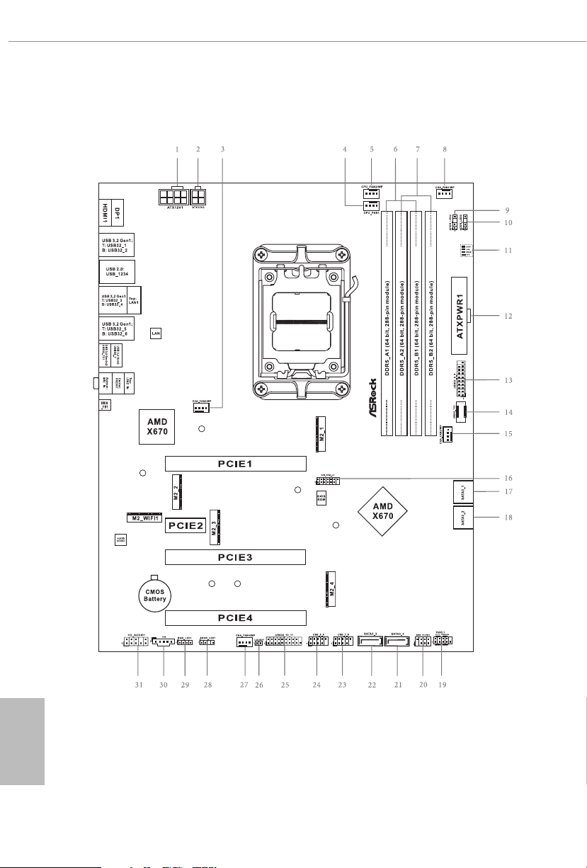
1.3 Motherboard Layout
English
6
Page 11

No. Description
1 8 pin 12V Power Connector (ATX12V1)
2 4 pin 12V Power Connector (ATX12V2)
3 Chassis/Water Pump Fan Connector (CHA_FAN3/WP)
4 CPU Fan Connector (CPU_FAN1)
5 CPU/Water Pump Fan Connector (CPU_FAN2/WP)
6 2 x 288-pin DDR5 DIMM Slots (DDR5_A1, DDR5_B1)
7 2 x 288-pin DDR5 DIMM Slots (DDR5_A2, DDR5_B2)
8 Chassis/Water Pump Fan Connector (CHA_FAN1/WP)
9 Addressable LED Header (ADDR_LED2)
10 Addressable LED Header (ADDR_LED3)
11 Post Status Checker (PSC)
12 ATX Power Connector (ATXPWR1)
13 USB 3.2 Gen1 Header (USB32_8_9)
14 Front Panel Type C USB 3.2 Gen2x2 Header (USB32_TC2)
15 Chassis/Water Pump Fan Connector (CHA_FAN2/WP)
16 SPI TPM Header (SPI_TPM_J1)
17 SATA3 Connector (SATA3_1)
18 SATA3 Connector (SATA3_2)
19 System Panel Header (PANEL1)
20 Power LED and Speaker Header (SPK_PLED1)
21 SATA3 Connector (SATA3_4)
22 SATA3 Connector (SATA3_3)
23 USB 2.0 Header (USB_7_8)
24 USB 2.0 Header (USB_5_6)
25 USB 3.2 Gen1 Header (USB32_10_11)
26 Clear CMOS Jumper (CLRCMOS1)
27 Chassis/Water Pump Fan Connector (CHA_FAN4/WP)
28 Addressable LED Header (ADDR_LED1)
29 RGB LED Header (RGB_LED1)
30 5-pin underbolt AIC Connector (TB1)
31 Front Panel Audio Header (HD_AUDIO1)
X670E PG Lightning
English
7
Page 12
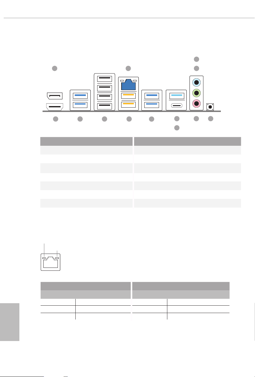
1.4 I/O Panel
3
21
4
English
1213
11 10
9
7
6
5
8
No. Description No. Description
1 DisplayPort 1.4 8 USB 3.2 Gen2x2 Type-C Port (USB32_TC1)
2 2.5G LAN RJ-45 Port* 9 USB 3.2 Gen1 Ports (USB32_56)
3 Line In (Light Blue)** 10 USB 3.2 Gen1 Ports (USB32 _34)***
4 Front Speaker (Lime)** 11 USB 2.0 Ports (USB_1234)
5 BIOS Flashback Button 12 USB 3.2 Gen1 Ports (USB32_12)
6 Microphone (Pink)** 13 HDMI Port
7 USB 3.2 Gen2 Type-A Port (USB32_7)
* ere are two LEDs on each LAN port. Please refer to the table below for the LA N port LED indic ations .
ACT/LINK L ED
SPEED LED
LAN Port
Activity / Link LED Speed LED
Status Description Status Description
O No Link O 10Mbps connection
Blinking Data Activity Orange 100Mbps/1Gbps connection
On Link Green 2.5Gbps connection
8
Page 13

** Function of the Audio Port s in 7.1-chann el Conguration:
Port Function
Light Blue (Rear panel) Rear Speaker Out
Lime (Rear panel) Front Speaker Out
Pink (Rear panel) Central /Subwoofer Spea ker Out
Lime (Front panel) Side Speaker Out
*** USB32_34 are Lightning Gaming Ports .
X670E PG Lightning
English
9
Page 14
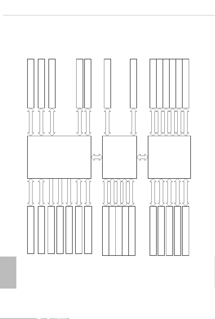
1.5 Block Diagram
x16 Gen5
Channel A
DDR5 Slot x2 PCIe 1 x16 Gen5 Slot
PCIE3(PCIe Gen4x4)
x4 Gen4
Channel B
DDR5 Slot x2
Flash ROM
M2_1 (PCIe Gen5x4)
x4 Gen5
AMD AM5
Processor
LGA1718
DP0
DP1
DP2 & 3
HDMI Port
DP Port
Rear USB3.0 Type A X2
SIO NCT6796D-S
SPI
eSPI
M.2_4(PCIe Gen4x4)
x4 Gen4
PCIe x4 Gen4 BUS
1st
Redriver
10Gb/s
AZ(HD Audio)
Rear USB3.0 port(LAN down)
Audio Codec ALC897 3
20Gb/s
5Gb/s
Front USB3.2 Gen2X2 Type C
Front USB 3.0 2 port
SATA 4 port
SATA 6Gb/s
AMD PROM21
Chipset
5Gb/s
480Mb/s
480Mb/s
Front USB 3.0 2 port
Rear USB 2.0 *4 down2
Front USB 2.0 2 port
M.2_2 (PCIe Gen3x4/SATA)
x4 Gen3
PCIe x4 Gen4 BUS
20Gb/s
(A+C)Rear TypeC USB3.2 GEN2
PCIe2 Gen4x1 Slot
x1 Gen4
Realtek RTL8125B 2.5G LAN
Key E WiFi
PCIe4 Gen4x1 Slot
x1 Gen4
2nd
10Gb/s
5Gb/s
Rear USB3.0 port(LAN up)
(A+C)Rear TypeA USB3.2 GEN2
AMD PROM21
M.2_3 (PCIe Gen4x2)
x1
x1
x2 Gen4
Chipset
480Mb/s
480Mb/s
Rear USB 2.0 *4 up2
Rear USB3.0 Type A X2
English
10
Page 15

X670E PG Lightning
Chapter 2 Installation
is is an ATX form factor motherboard. Before you install the motherboard, study
the conguration of your chassis to ensure that the motherboard ts into it.
Pre-installation Precautions
Take note of the following precautions before you install motherboard components
or change any motherboard settings.
Make sure to unplug the power cord before installing or removing the motherboard
•
components. Failure to do so may cause physical injuries and damages to motherboard
components.
In order to avoid damage from static electricity to the motherboard’s components,
•
NEVER place your motherboard directly on a carpet. Also remember to use a
grounded wrist strap or touch a safety grounded object before you handle the
components.
Hold components by the edges and do not touch the ICs.
•
Whenever you uninstall any components, place them on a grounded anti-static pad or
•
in the bag that comes with the components.
When placing screws to secure the motherboard to the chassis, please do not over-
•
tighten the screws! Doing so may damage the motherboard.
11
English
Page 16
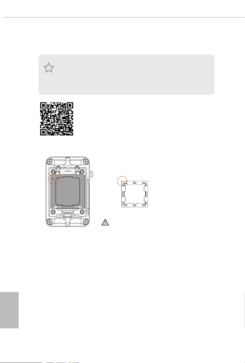
2.1 Installing the CPU
1. Before you inser t the 1718-Pin CPU into the sock et, please check if the P nP cap
is on the socket, if the CPU surface is unclean , or if there are any bent pins in the
socket. Do not force to insert the CPU into the socket if above situation is found.
Other wise, the CPU wil l be seriously damaged.
2. Unplug all power cables before installing the CPU.
Tutorial Video
English
12
Turn your CPU to the correct orientation before opening
the CPU socket cover.
Page 17
X670E PG Lightning
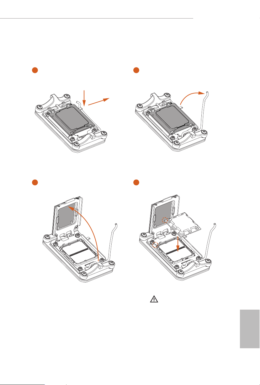
1
A
B
3
2
4
Carefully place the CPU in as at as
possible. Do not drop it.
13
English
Page 18
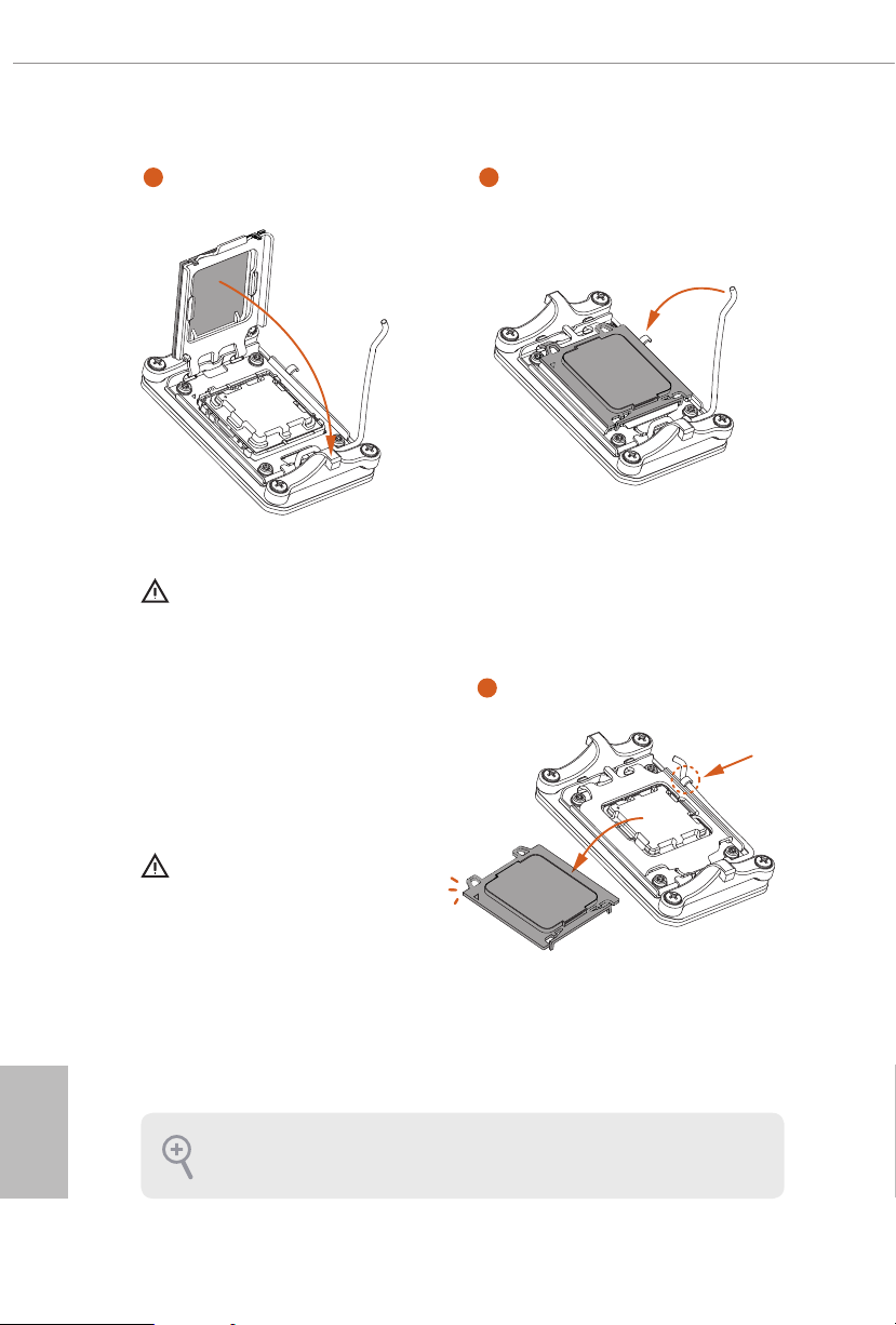
5
Make sure the CPU is aligned with the
socket before locking it into place.
6
7
English
14
Make sure the black cover plate
is always in place until it pops o
when closing the socket lever.
Please save the cover if the pro cessor is removed. e cover must be placed if you wish
to return the mothe rboard for aer ser vice.
Page 19
X670E PG Lightning
2.2 Installing the CPU Fan and Heatsink
Aer you install the CPU into this motherboard, it is necessary to install a larger
heatsink and cooling fan to dissipate heat. You also need to spray thermal grease
between the CPU and the heatsink to improve heat dissipation. Make sure that the
CPU and the heatsink are securely fastened and in good contact with each other.
Please turn o the power or remove the power cord before chang ing a CPU or heatsink .
Installing the CPU Cooler (Type 1)
1
2
English
15
Page 20
3
4
English
16
CPU_FAN1
Page 21

Installing the CPU Cooler (Type 2)
1
2
X670E PG Lightning
17
English
Page 22

3
4
English
18
CPU_FAN1
Page 23

X670E PG Lightning
5
CPU_FAN1
RGB_LED1
+12V
*e illustrations shown here are for reference purposes only and may not exactly match
the model you purchase.
19
English
Page 24

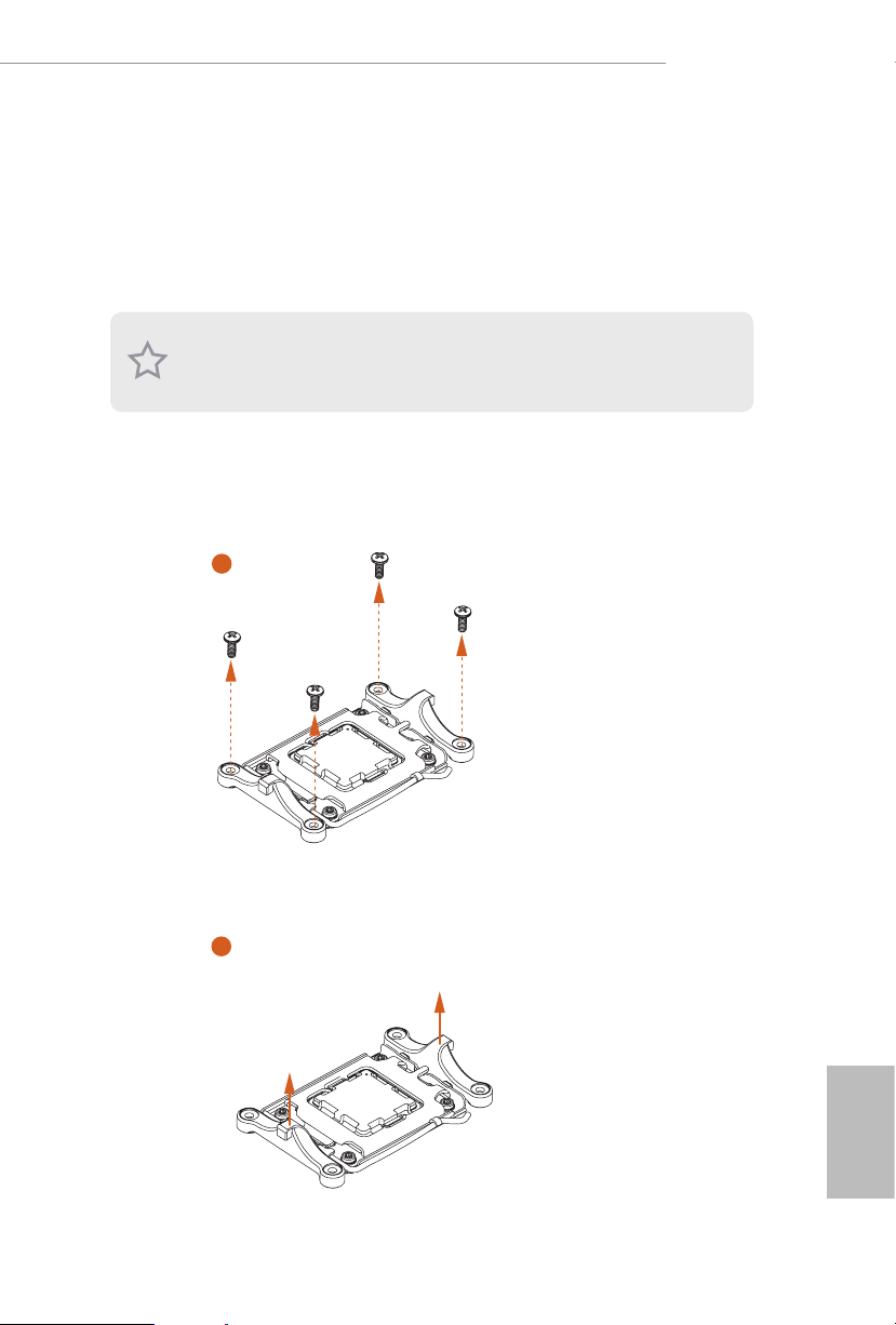
Installing the CPU Cooler (Type 3)
1
2
English
20
Page 25

X670E PG Lightning
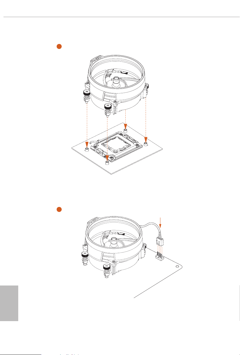
3
4
21
English
Page 26

5
CPU_FAN1
English
22
Page 27

X670E PG Lightning
6
CPU_FAN1
RGB_LED1
+12V
or
CPU_FAN1
RGB_LED1
USB_1_2
Please note that only one cable should be used at a time in this step.
If you select RGB_LED1, please install ASRock utility "ASRock Polychrome SYNC".
If you select USB connector, please install AMD utility "SR3 Settings Soware".
*e illustrations shown here are for reference purposes only and may not exactly match
the model you purchase.
English
23
Page 28

2.3 Installing Memory Modules (DIMM)
is motherboard provides four 288-pin DDR5 (Double Data Rate 5) DIMM slots,
and supports Dual Channel Memory Technology.
1. For dual channel conguration, you always need to install identical (the same
brand, speed, size and chip-type) DDR5 DIMM pairs.
2. It is unable to activate Dual C hannel Memory Technology with only one or three
memor y module installed.
3. It is not allowed to in stall a DDR, DDR2 , DDR3 or DDR4 memory module into a
DDR5 slot; otherwise, this motherboard an d DIMM may be damaged.
4. e DIMM only ts in one correct orientation. It w ill cause per manent d amage to
the mothe rboard and the DIMM if you force the DIMM into the slot at incorrect
orientation.
Recommended Memory Conguration
1 DIMM
A1 A2 B1 B2
V
2 DIMMs
A1 A2 B1 B2
V V
4 DIMMs
A1 A2 B1 B2
V V V V
English
24
e rst boot may take some time.
Please be patient and refer to the following table for booting time.
*It may vary by dierent setups.
Memory 1st boot after clear CMOS
2 x 16GB 90 sec
2 x 32GB 150 sec
4 x 16GB 170 sec
4 x 32GB 315 sec
Page 29

X670E PG Lightning
1
2
3
English
25
Page 30

2.4 Connecting the Front Panel Header
1
32:(56:
+''/('
5(6(76:
32:(5/('
32:(5/('
2
RESET SW
HDD LED
English
26
3$1(/
System Panel Header
910
Power SW (-) RESET SW (+)
B
Power LED (-)
A
Power LED (+)
12
PANEL1
RESET SW (-)Power SW (+)
HDD LED (-)
HDD LED (+)
Front Panel Wires
D
C
A B C D
Page 31

2.5 Installing the Motherboard
X670E PG Lightning
27
English
Page 32

2.6 Installing SATA Drives
1
Optical Drive
SATA Drive
2
English
28
SATA Data Cable
Page 33

X670E PG Lightning
3
4
SATA Power Connector
SATA Data Connector
English
29
Page 34

2.7 Installing a Graphics Card
1
CLICK!
English
30
Page 35

Expansion Slots (PCIe Slots)
ere are 4 PCI Express slots on the motherboard.
Before installing an expansion card, please make sure that the power supply is
switched o or the power cord i s unplugged. Please read the document ation of the
expan sion card and mak e neces sary hardware settings for the card before you start
the installation.
PCIe slots:
PCIE1 (PCIe 5.0 x16 slot) is used for PCIe x16 lane width graphics cards.
PCIE2 (PCIe 4.0 x1 slot) is used for PCIe x1 lane width cards.
PCIE3 (PCIe 4.0 x16 slot) is used for PCIe x4 lane width graphics cards.
PCIE4 (PCIe 4.0 x16 slot) is used for PCIe x1 lane width cards.
PCIe Slot Congurations
PCIE1 PCIE3
Single Graphics Card Gen5x16 N/A
X670E PG Lightning
Two Graphics Cards in
CrossFireTM Mode
For a better ther mal environment , please connect a chassis fan to the mothe rboard’s
chassis fan connector (CHA_FAN1~4 /WP) when using multiple graphics cards.
Gen5x16 Gen4x4
English
31
Page 36

2.8 Connecting Peripheral Devices
English
32
Page 37

2.9 Connecting the Power Connectors
X670E PG Lightning
$7;9
$7;3:5
English
33
Page 38

2.10 Power On
1
2
3
4
English
34
Page 39

X670E PG Lightning
2.11 Jumpers Setup
e illustration shows how jumpers are setup. When the jumper cap is placed on
the pins, the jumper is “Short”. If no jumper cap is placed on the pins, the jumper is
“Open”.
Clear CMOS Jumper
(CLRCMOS1) (see p.6, No. 26)
CLRCMOS1 allows you to clear the data in CMOS. e data in CMOS includes
system setup information such as system password, date, time, and system setup
parameters. To clear and reset the system parameters to default setup, please
turn o the computer and unplug the power cord, then use a jumper cap to short
the pins on CLRCMOS1 for 3 seconds. Please remember to remove the jumper
cap aer clearing the CMOS. If you need to clear the CMOS when you just nish
updating the BIOS, you must boot up the system rst, and then shut it down
before you do the clear-CMOS action.
CLRCMOS1
2-pin Jumper
Short: Clear CMOS
Open: Default
English
35
Page 40

2.12 Onboard Headers and Connectors
Onboard headers and connectors are NOT jumpers. Do NOT place jumpe r caps over
System Panel Header
(9-pin PANEL1) (see p.6, No. 19)
Connect the power button, reset button and system status indicator on the chassis
to this header according to the pin assignments below. Note the positive and
negative pins before connecting the cables.
these headers and conne ctors. Placing jumper caps over the headers and conn ectors
will cause per manent damage to the mothe rboard.
PANEL1
PLE D+
PLE D-
PWR BTN #
GND
English
36
1
HDL ED+
GND
HDL ED-
GND
RES ET#
PWRBTN (Power But ton):
Connec t to the power button on the chassis front panel. You may congure the way
to turn o your system using the power button.
RESET (Reset Button):
Connec t to the reset button on the chassis f ront panel. Pre ss the reset button to
restar t the computer if the computer freezes and fails to perform a normal restart.
PLED (Syste m Power LED):
Connec t to the power status indic ator on the chassis front panel. e LED is on when
the system is operating. e LED keeps blinking when the system is in S1/S3 sleep
state. e LED is o when the system is in S 4 sleep state or powered o (S5).
HDLED (Ha rd Drive Activity LED):
Connec t to the hard drive ac tivity L ED on the chassis front panel. e LED is on
when the hard drive i s reading or writing data.
e front panel design may dier by chassis. A front panel module mainly consists
of power button, reset but ton, power LED, hard drive activity LED, speaker and etc.
When connecting your chassis front panel module to this header, make sure the wire
assig nments and the pin assignments are matched correctly.
Page 41

Power LED and Speaker Header
PLE D-
SPE AKE R
(7-pin SPK_PLED1) (see p.6, No. 20)
Please connect the chassis power LED and the chassis speaker to this header.
SPK_PLED1
DUM MY
DUM MY
+5V
1
PLE D+
PLE D+
Serial ATA3 Connectors
Right Angle:
(SATA3_1) (see p.6, No. 17)
(SATA3_2) (see p.6, No. 18)
Vertical:
(SATA3_3) (see p.6, No. 22)
(SATA3_4) (see p.6, No. 21)
ese four SATA3 connectors support SATA data cables for internal storage
devices with up to 6.0 Gb/s data transfer rate.
X670E PG Lightning
SATA3_2 SATA3_1
SATA3_3 SATA3_4
English
37
Page 42

IntA _P_D+
English
38
USB 2.0 Headers
(9-pin USB_5_6) (see p.6, No. 24)
(9-pin USB_7_8) (see p.6, No. 23)
ere are two headers on this motherboard. Each USB 2.0 header can support
two ports.
USB_5_6
USB _PW R
-B
+B
GND
DUM MY
1
GND
+A
-A
USB _PW R
USB_7_8
USB _PW R
-B
+B
GND
DUM MY
1
GND
+A
-A
USB _PW R
USB 3.2 Gen1 Headers
(19-pin USB32_8_9) (see p.6, No. 13)
(19-pin USB32_10_11) (see p.6, No. 25)
ere are two headers on this motherboard. Each USB 3.2 Gen1 header can
support two ports.
USB32_8_9
Vbus
IntA _PA_SS RX-
IntA _PA_SS RX+
GND
IntA _PA_SS TX-
IntA _PA_SS TX+
GND
IntA _PA_D-
IntA _PA_D+
VbusVbus
IntA _PB_ SSRX-
IntA _PB_ SSRX+
GND
IntA _PB_ SSTX-
IntA _PB_ SSTX+
GND
IntA _PB_ D-
IntA _PB_ D+
Dumm y
1
USB32_10_11
IntA _P_D-
GND
IntA _P_SS TX+
IntA _P_SS TX-
GND
IntA _P_SS RX+
IntA _P_SS RX-
Vbus
1
IntA _P_D+
ID
GND
IntA _P_D-
GND
IntA _P_SS TX-
IntA _P_SS TX+
Vbus
IntA _P_SS RX-
IntA _P_SS RX+
Page 43

X670E PG Lightning
Front Panel Type C USB 3.2 Gen2x2 Header
(20-pin USB32_TC2) (see p.6, No. 14)
ere is one Front Panel Type C USB 3.2 Gen2x2 Header on this motherboard.
is header is used for connecting a USB 3.2 Gen2x2 module for additional USB 3.2
Gen2x2 ports.
USB32_TC2
USB Type-C Cable
Front Panel Audio Header
(9-pin HD_AUDIO1) (see p.6, No. 31)
is header is for connecting audio devices to the front audio panel.
HD_AUDIO1
GND
PRE SEN CE#
MIC _RE T
OUT _RE T
1
High Denition Audio supports Jack S ensing, but the panel wire on the chassis mu st
suppor t HDA to function correctly. Please follow the instr uctions in our manual and
chassis manu al to install your system.
MIC 2_R
MIC 2_L
J_S ENS E
OUT 2_R
OUT 2_L
English
39
Page 44

Chassis/Water Pump Fan Connectors
GND
GND
4
(4-pin CHA_FAN1/WP) (see p.6, No. 8)
(4-pin CHA_FAN2/WP) (see p.6, No. 15)
(4-pin CHA_FAN3/WP) (see p.6, No. 3)
(4-pin CHA_FAN4/WP) (see p.6, No. 27)
is motherboard provides four 4-Pin water cooling
plan to connect a 3-Pin
chassis
water cooler fan, please connect it to Pin 1-3.
chassis
fan connectors. If you
CHA_FAN4/WP
FAN _VO LTAG E
CHA _FA N_SP EED
FAN _SP EED_ CON TRO L
1 2 3 4
CHA_FAN1/WP
FAN _SPE ED_ CON TRO L
CHA _FAN _SP EED
FAN _VO L TAG E
CHA_FAN2/WP
FAN _SPE ED_ CON TROL
CHA _FAN _SP EED
FAN _VO L TAG E
CHA_FAN3/WP
FAN _VO LTAG E
CHA _FA N_SP EED
FAN _SP EED_ CON TRO L
1 2 3 4
4 3 2 1
GND
GND
3
2
1
English
40
Page 45

X670E PG Lightning
CPU Fan Connector
(4-pin CPU_FAN1) (see p.6, No. 4)
is motherboard provides a 4-Pin CPU fan (Quiet Fan) connector. If you plan to
connect a 3-Pin CPU fan, please connect it to Pin 1-3.
CPU_FAN1
4 3 2 1
GND
+12 V
FAN_ SPE ED_C ONT ROL
CPU _FAN _SPE ED
CPU/Water Pump Fan Connector
(4-pin CPU_FAN2/WP) (see p.6, No. 5)
is motherboard provides a 4-Pin water cooling CPU fan connector. If you plan
to connect a 3-Pin CPU water cooler fan, please connect it to Pin 1-3.
CPU_FAN2/WP
4 3 2 1
GND
FAN_ VOLTA GE
CPU_ F
AN_S PEED
FAN_S PEED_ CONTR OL
English
41
Page 46

ATX Power Connector
8 5
(24-pin ATXPWR1) (see p.6, No. 12)
is motherboard provides a 24-pin ATX power connector. To use a 20-pin ATX
power supply, please plug it along Pin 1 and Pin 13.
ATXPWR1
12
24
1
13
ATX 12V Power Connector
(8-pin ATX12V1) (see p.6, No. 1)
is motherboard provides a 8-pin ATX 12V power connector. To use a 4-pin
ATX power supply, please plug it a long Pin 1 and Pin 5.
*Warning: Please make sure that the power cable connected is for the CPU and
not the graphics card. Do not plug the PCIe power cable to this
connector.
English
42
ATX12V1
4
1
Page 47

ATX 12V Power Connector
(4-pin ATX12V2) (see p.6, No. 2)
Please connect an ATX 12V power supply to this connector.
*e power supply plug ts into this connector in only one orientation.
*Connecting an ATX 12V 4-pin cable to ATX12V2 is optional.
*For advanced overclocking we suggest using this connector together with
ATX12V1.
ATX12V2
X670E PG Lightning
43
English
Page 48

SPI TPM Header
SPI_ DQ3
(13-pin SPI_TPM_J1) (see p.6, No. 16)
is connector supports SPI Trusted Platform Module (TPM) system, which can
securely store keys, digital certicates, passwords, and data. A TPM system also
helps enhance network security, protects digital identities, and ensures platform
integrity.
SPI_TPM_J1
SPI_ PWR
Dumm y
CLK
SPI_ MOSI
RST#
TPM_ PIRQ
1
SPI_ DQ2
SPI_ MISO
SPI_ CS0
GND
RSMR ST#
SPI_ TPM_ CS#
underbolt AIC Connecto
(5-pin TB1) (see p.6, No. 30)
Please connect a underbolt™ add-in card (AIC) to the underbolt AIC connec-
tor via the GPIO cable.
*Please install the underbolt™ AIC card to PCIE3 (default slot).
*For the underbolt compatibility and limitation, please visit www.asrock.com.
TB1
English
44
Page 49

X670E PG Lightning
RGB LED Header
(4-pin RGB_LED1) (see p.6, No. 29)
is RGB header is used to connect RGB LED extension cable which allow users to
choose from various LED lighting eects.
Caution: Never install the RGB LED cable in the wrong orientation; otherwise, the
cable may be damaged.
RGB_LED1
1
+12 V G R B
Connect your RGB LED strip to the
LED Header (RGB_LED1)
on the mother-
board.
1. Never in stall the RGB LED cable in the wrong orientation; other wise, the cable
may be damaged.
2. Before installing or removing your RGB LED cable, plea se power o your system
and unplug the power cord from the power supply. Failure to do so may cause damages to motherboard components.
1. Please note that the RGB LED str ips do not come with the package.
2. e RGB LED header support s standard 5050 RGB LED s trip (12V/G/R/B), with a
maximum power rating of 3A (12V) and length within 2 meters.
RGB
1
B
R
G
V
2
1
English
45
Page 50

Addressable LED Headers
(3-pin ADDR_LED1) (see p.6, No. 28)
(3-pin ADDR_LED2) (see p.6, No. 9)
(3-pin ADDR_LED3) (see p.6, No. 10)
ese headers are used to connect
Addressable
LED extension cables which allow users
to choose from various LED lighting eects.
Caution: Never install the Addressable LED cable in the wrong orientation; otherwise,
the cable may be damaged.
ADDR_LED3
ADDR_LED2
ADDR_LED1
1
GND
DO_ ADD R
VOU T
English
46
Connect your
to the
Addressable RGB LED
strips
Addressable LED Headers (ADDR_
LED1 / ADDR_LED2 / ADDR_LED3)
the motherboard.
on
1
Page 51

1. Never in stall the RGB LED cable in the wrong orientation; other wise, the cable
may be damaged.
2. Before installing or removing your RGB LED cable, plea se power o your system
and unplug the power cord from the power supply. Failure to do so may cause damages to motherboard components.
1. Please note that the RGB LED str ips do not come with the package.
2. e RGB LED header support s WS2812B addressable RGB LED str ip (5V/Data/
GND), with a ma ximum power rating of 3A (5V) and length within 2 meters.
X670E PG Lightning
47
English
Page 52

2.13 Smart Switches
e motherboard has one smart switch: BIOS Flashback Button, allowing users to
ash the BIOS.
BIOS Flashback Button
(BIOS_FB1) (see p.8, No. 5)
BIOS Flashback Button allows users to ash the BIOS.
BIOS_FB1
English
48
USB BIOS Flashback port
Page 53

X670E PG Lightning
ASRock BIOS Flashback feature allows you to update BIOS without powering on t he system,
even wit hout CPU.
Before u sing the BIOS Flashback function, plea se suspend BitLocker and any encryption or security relying on the TPM. Make sure that you have already stored and
backup -ed the recovery key. If the recover y key is missing while encryption is ac tive,
the data w ill stay encrypted and the syste m will not boot into the operating system . It
is recommended to disable fTPM before updating the BIOS. Otherwise an unpredictable failure may occ ur.
To use the USB BIOS Flashback f unction, Please follow the steps below.
1. Download the latest BIOS le from ASRock 's website : http://ww w.asrock.com.
2. Copy t he BIOS le to your USB ash d rive. Please make sure the le system of
your USB ash drive must be FAT32.
3. Extract BIOS le from the zip le.
4. Rename the le to “creative.rom” and save it to t he root director y of X: USB ash drive.
5. Plug the 24 pin power connector to the motherboard. en turn on the power supply's AC
switch.
*ere is no need to power on the system.
6. en plug you r USB drive to the USB BIOS Flashback port.
7. Press the BIOS Flashback Switch for about three seconds. en the LED star ts to blink.
8. Wait unti l the LED stops bli nki ng, ind icating that BIOS ashing has been completed.
*If the LED light turns solid green, this means that the BIOS Flashback is not
operating properly. Please make sure that you plug the USB drive to the USB BIOS Flashback
port.
**If the LED does not light up at all then please disconnect power from the system and
remove/disconnect the CMOS bat tery from the mot herboard for several minutes. Reconnect
power and battery and try again.
49
English
Page 54

2.14 Post Status Checker
Post Status Checker (PSC) diagnoses the computer when users power on the
machine. It emits a red light to indicate whether the CPU, memory, VGA or storage is
dysfunctional. e lights go o if the four mentioned above are functioning normally.
English
50
It is normal for the DR AM status LED to blink during memory training. is indicates the system is working properly.
Tutorial Video
Page 55

X670E PG Lightning
2.15 M.2 SSD Module Installation Guide (M2_1)
e M.2 is a small size and versatile card edge connector that aims to replace mPCIe and
mSATA. e Blazing M.2 Socket (M2_1, Key M) supports type 2280 PCIe Gen5x4 (128
Gb/s) mode.
Installing the M.2 SSD Module
Step 1
Prepare a M.2 SSD module and the
screw.
Step 2
Depending on the PCB t ype and
length of your M.2 SSD module, nd
the corresponding nut location to be
used.
No. 1
Nut Location A
PCB Length 8cm
Module Type Type 2280
English
51
Page 56

1
Step 3
2
Before installing a M.2 SSD
1
module, please loosen the screws to
remove the M.2 heatsink.
*Please remove the protective lms
on the bottom side of the M.2
heatsink before you install a M.2
SSD module.
Step 4
Align and gently insert the M.2 SSD
module into the M.2 slot. Please
be aware that the M.2 SSD module
only ts in one orientation.
A
English
52
A
o
20
Page 57

Correct Installation:
e SSD's PCB is in proper place, and
the M.2 heatsink can be screwed in.
X670E PG Lightning
Step 5
Before securing the M.2 heatsink,
make sure to align the notch on
the SSD to the stando on the
motherboard; otherwise, the SSD
module may be damaged.
Incorrect Installation:
e SSD's PCB sits between M.2 heatsink
and stando. Do not continue.
English
53
Page 58

3
Step 6
1
2
For the latest updates of M.2 SSD module support list, please visit our website for details:
http://ww w.asrock.com
Tighten the screws with a screwdriver
to secure the module and M.2
heatsink into place in the order
shown. Tighten screw opposite the
M.2 connector rst (2), and then
tighten the one next to the M.2
connector (3).
*Please do not overtighten the screw
as this might damage the module and
M.2 heatsink.
English
54
Page 59

X670E PG Lightning
2.16 M.2 SSD Module Installation Guide (M2_2 and M2_3)
e M.2 is a small size and versatile card edge connector that aims to replace mPCIe and
mSATA. e Ultra M.2 Socket (M2_2, Key M) supports type 2280 SATA3 6.0 Gb/s & PCIe
Gen3x4 (32 Gb/s) modes. e M.2 Socket (M2_3, Key M) supports type 2280 PCIe Gen4x2
(32 Gb/s) mode
Installing the M.2 SSD Module
Step 1
Prepare a M.2 SSD module and the
screw.
Step 2
Depending on the PCB t ype and
length of your M.2 SSD module, nd
the corresponding nut location to be
used.
No. 1
Nut Location A
PCB Length 8cm
Module Type Type 2280
English
55
Page 60

Step 3
Align and gently insert the M.2 SSD
module into the M.2 slot. Please
be aware that the M.2 SSD module
only ts in one orientation.
A
English
A
o
20
Step 4
Tighten the screw with a screwdriver
to secure the module into place.
Please do not overtighten the screw
NUT1NUT2
as this might damage the module.
For the latest updates of M.2 SSD module support list, please visit our website for details:
http://ww w.asrock.com
56
Page 61

X670E PG Lightning
2.17 M.2 SSD Module Installation Guide (M2_4)
e M.2 is a small size and versatile card edge connector that aims to replace mPCIe and
mSATA. e Hyper M.2 Socket (M2_4, Key M) type 2260/2280 PCIe Gen4x4 (64 Gb/s)
mode.
Installing the M.2 SSD Module
Step 1
Prepare a M.2 SSD module and the
screw.
Step 2
Depending on the PCB t ype and
length of your M.2 SSD module, nd
the corresponding nut location to be
used.
No. 1 2
Nut Location A B
PCB Length 6cm 8cm
Module Type Type 2260 Type 2280
English
57
Page 62

1
Step 3
2
1
module, please loosen the screws to
remove the M.2 heatsink.
*Please remove the protective lms
on the bottom side of the M.2
heatsink before you install a M.2
SSD module.
Step 4
Peel o the yellow protective lm on
the nut A. Prepare the M.2 stando
that comes with the package, and
hand tighten it into the nut A. Skip
Step 4 if your M.2 SSD module is
Type 2280.
Step 5
Align and gently insert the M.2 SSD
module into the M.2 slot. Please
be aware that the M.2 SSD module
only ts in one orientation.
Before installing a M.2 SSD
AB
o
20
English
58
AB
Page 63

X670E PG Lightning
Step 6
Tighten the screw with a screwdriver
to secure the module into place.
Please do not overtighten the screw
NUT1NUT2B
as this might damage the module.
Skip Step 6 if your M.2 SSD module is
Type 2280.
Step 7
Before securing the M.2 heatsink,
make sure to align the notch on
the SSD to the stando on the
motherboard if you use a Type 2280
SSD module; otherwise, the SSD
module may be damaged.
Correct Installation:
e SSD's PCB is in proper place, and
the M.2 heatsink can be screwed in.
Incorrect Installation:
e SSD's PCB sits between M.2 heatsink
and stando. Do not continue.
English
59
Page 64

3
Step 8
1
2
For the latest updates of M.2 SSD module support list, please visit our website for details:
http://ww w.asrock.com
Tighten the screws with a screwdriver
to secure the module (if your M.2
SSD module is Type 2280) and M.2
heatsink into place in the order
shown. Tighten screw opposite the
M.2 connector rst (2), and then
tighten the one next to the M.2
connector (3).
*Please do not overtighten the screw
as this might damage the module and
M.2 heatsink.
English
60
Page 65

Version 1.1
Published August 2022
Copyright©2022 ASRock INC. All rights reserved.
Copyright Notice:
No part of this documentation may be reproduced, transcribed, transmitted, or
translated in any language, in any form or by any means, except duplication of
documentation by the purchaser for backup purpose, without written consent of
ASRock Inc.
Products and corporate names appearing in this documentation may or may not
be registered trademarks or copyrights of their respective companies, and are used
only for identication or explanation and to the owners’ benet, without intent to
infringe.
Disclaimer:
Specications and information contained in this documentation are furnished for
informational use only and subject to change without notice, and should not be
constructed as a commitment by ASRock. ASRock assumes no responsibilit y for
any errors or omissions that may appear in this documentation.
With respect to the contents of this documentation, ASRock does not provide
warranty of any kind, either expressed or implied, including but not limited to
the implied warranties or conditions of merchantability or tness for a particular
purpose.
In no event shall ASRock, its directors, ocers, employees, or agents be liable for
any indirect, special, incidental, or consequential damages (including damages for
loss of prots, loss of business, loss of data, interruption of business and the like),
even if ASRock has been advised of the possibility of such damages arising from
any defect or error in the documentation or product.
is device complies with Part 15 of the FCC Rules. Operation is subject to the following
two conditions:
(1) this device may not cause harmful interference, and
(2) this device must accept any interference received, including interference that
may cause undesired operation.
e terms HDMI® and HDMI High-Denition Multimedia Interface, and the HDMI
logo are trademarks or registered trademarks of HDMI Licensing LLC in the United
States and other countries.
Page 66

WARNING
THIS PRODUCT CONTAINS A BUTTOON BATTERY
If swallowed, a button battery can cause serious injury or death.
Please keep batteries out of sight or reach of children.
CALIFORNIA, USA ONLY
e Lithium batter y adopted on this motherboard contains Perchlorate, a toxic substance
controlled in Perchlorate Best Management Practices (BMP) regulations passed by the
California Legislature. When you discard the Lithium battery in California, USA, please
follow the related regulations in advance.
“Perchlorate Material-special handling may apply, see www.dtsc.ca.gov/hazardouswaste/
perchlorate”
AUSTRALIA ONLY
Our goods come with guarantees that cannot be excluded under the Australian Consumer
Law. You are entitled to a replacement or refund for a major failure and compensation for
any other reasonably foreseeable loss or damage caused by our goods. You are also entitled
to have the goods repaired or replaced if the goods fail to be of acceptable quality and the
failure does not amount to a major failure. If you require assistance please call ASRock Tel
: +886-2-28965588 ext.123 (Standard International call charges apply)
ASRock INC. hereby declares that this device is in compliance with the essential requirements and other relevant provisions of related UKCA Directives. Full text of UKCA
declaration of conformity is available at: http://www.asrock.com
ASRock INC. hereby declares that this device is in compliance with the essential requirements and other relevant provisions of related Directives. Full text of EU declaration of
conformity is available at: http://www.asrock.com
ASRock follows the green design concept to design and manufacture our products, and
makes sure that each stage of the product life cycle of ASRock product is in line with
global
environmental regulations. In addition, ASRock disclose the relevant information based
on regulation requirements.
Please refer to https://www.asrock.com/general/about.asp?cat=Responsibility for information disclosure based on regulation requirements ASRock is complied with.
DO NOT throw the motherboard in municipal waste. is product has been
designed to enable proper reuse of parts and recycling. is symbol of the
crossed out wheeled bin indicates that the product (electrical and electronic
equipment) should not be placed in municipal waste. Check local regulations
for disposal of electronic products.
 Loading...